Nivotester FTW 325 (Technical Information)
16
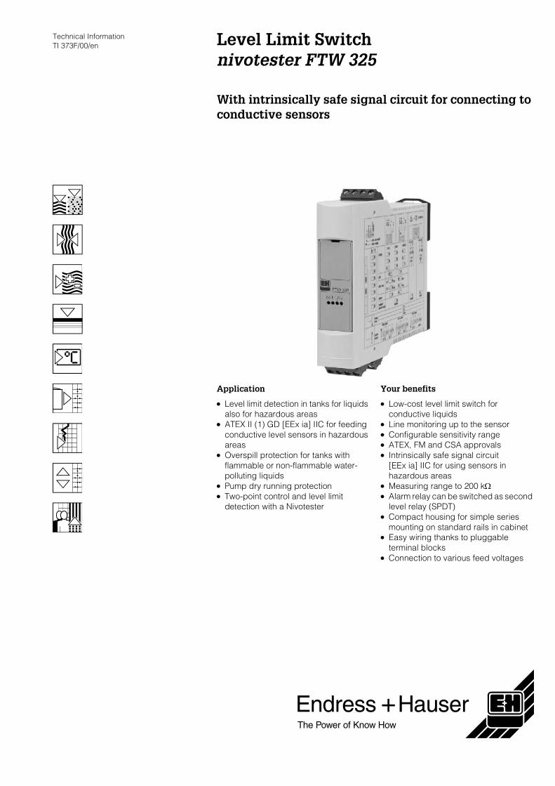
Technical Information TI 373F/00/en Level Limit Switch nivotester FTW 325 With intrinsically safe signal circuit for connecting to conductive sensors Application • Level limit detection in tanks for liquids also for hazardous areas • ATEX II (1) GD [EEx ia] IIC for feeding conductive level sensors in hazardous areas • Overspill protection for tanks with flammable or non-flammable water- polluting liquids • Pump dry running protection • Two-point control and level limit detection with a Nivotester Your benefits • Low-cost level limit switch for conductive liquids • Line monitoring up to the sensor • Configurable sensitivity range • ATEX, FM and CSA approvals • Intrinsically safe signal circuit [EEx ia] IIC for using sensors in hazardous areas • Measuring range to 200 kΩ • Alarm relay can be switched as second level relay (SPDT) • Compact housing for simple series mounting on standard rails in cabinet • Easy wiring thanks to pluggable terminal blocks • Connection to various feed voltages
Transcript of Nivotester FTW 325 (Technical Information)
Technical Information TI 373F/00/en Level Limit Switch
nivotester FTW 325
With intrinsically safe signal circuit for connecting to conductive sensors
Application
• Level limit detection in tanks for liquids also for hazardous areas
• ATEX II (1) GD [EEx ia] IIC for feeding conductive level sensors in hazardous areas
• Overspill protection for tanks with flammable or non-flammable water-polluting liquids
• Pump dry running protection • Two-point control and level limit
detection with a Nivotester
Your benefits
• Low-cost level limit switch for conductive liquids
• Line monitoring up to the sensor • Configurable sensitivity range • ATEX, FM and CSA approvals • Intrinsically safe signal circuit
[EEx ia] IIC for using sensors in hazardous areas
• Measuring range to 200 kΩ • Alarm relay can be switched as second
level relay (SPDT) • Compact housing for simple series
mounting on standard rails in cabinet • Easy wiring thanks to pluggable
terminal blocks • Connection to various feed voltages
Nivotester
2 Endress + Hauser
Function and system design
Measuring principle Function
The Nivotester sends a small alternating current* to the measuring point via the signal line. The line is connected to the ground probe or the metal container and the measuring probe. If an electrically conductive product comes in contact with the measuring probe, a voltage drops out. An amplifier circuit in the Nivotester causes the relay(s) to switch.
* The use of an alternating current prevents electrolysation of the probe rods and the product.
Signal transmission
The intrinsically safe signal input of the limit switch Nivotester FTW 325 is galvanically isolated from the mains and the output. The Nivotester supplies the conductive probe with alternating current via a two-wire or three-wire line and monitors the voltage of this line. If the product reaches the switch point of the probe, the voltage between the probe and Nivotester is reduced. The output relays at the Nivotester switch depending on the set fail-safe mode. Two yellow light emitting diodes on the front panel of the Nivotester indicate the relay switch status.
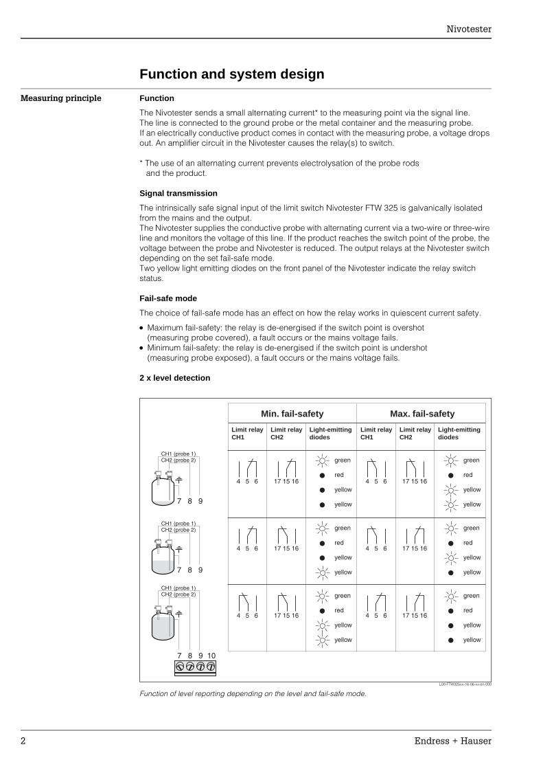
Fail-safe mode
The choice of fail-safe mode has an effect on how the relay works in quiescent current safety.
• Maximum fail-safety: the relay is de-energised if the switch point is overshot(measuring probe covered), a fault occurs or the mains voltage fails.
• Minimum fail-safety: the relay is de-energised if the switch point is undershot(measuring probe exposed), a fault occurs or the mains voltage fails.
2 x level detection
L00-FTW325xx-16-06-xx-en-000
Function of level reporting depending on the level and fail-safe mode.
4 5 6 4 5 6
4 5 6 4 5 6
4 5 6 4 5 6
17 15 16 17 15 16
17 15 16 17 15 16
17 15 16 17 15 16
7 8 9 10
7 8 9
7 8 9
Light-emittingdiodes
Light-emittingdiodes
Limit relayCH1
Limit relayCH1
Limit relayCH2
Limit relayCH2
Max. fail-safetyMin. fail-safety
green
red
yellow
yellow
green
red
yellow
yellow
green
red
yellow
yellow
green
red
yellow
yellow
green
red
yellow
yellow
green
red
yellow
yellow
CH1 (probe 1)CH2 (probe 2)
CH1 (probe 1)CH2 (probe 2)
CH1 (probe 1)CH2 (probe 2)
Nivotester
Endress + Hauser 3
Function monitoring
To increase operational safety, channel 1 (CH1) of the Nivotester is equipped with function monitoring. A fault is indicated by a red light emitting diode and de-energises the relay for the level alarm and the alarm relay at CH1. A fault is reported if too high a voltage is measured. This can occur, for example, if:
• The signal line to the sensor is disconnected • The sensor electronics are faulty
Line monitoring takes place via probe types with an additional printed circuit board.This line monitoring is switched on and off by means of a DIL switch on the Nivotester.
Probes with integrated line monitoring
• Liquipoint T, FTW 31/32 (separately instrumented) • 11 362 • 11 362 Z • 11 363 • 11 363 Z • 11 375 ZF • 11 961 ZF
Configurable switching delay
A slide switch allows you to set a switching delay of 0.5 s; 2 s; 6 s. The switching delay is only effective when the relay is energised - see also fail-safe mode.
Fail-safe mode can be set separately
Two DIL switches allow separate MIN/MAX setting for CH1 and CH2.
Sensitivity range
Three resistance ranges can be set with DIL switches.
• Up to 1.0 kΩ • Up to 10.0 kΩ • Up to 200.0 kΩ (standard setting for most liquids)
A trimmer is used for fine adjustment.
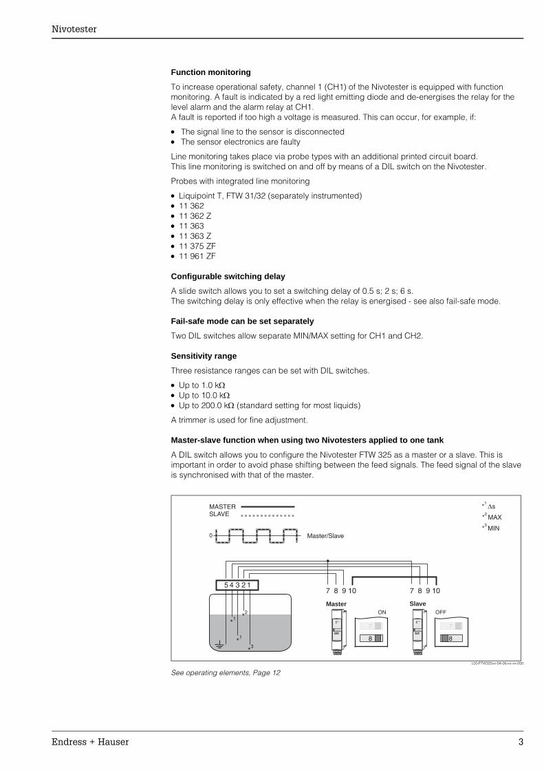
Master-slave function when using two Nivotesters applied to one tank
A DIL switch allows you to configure the Nivotester FTW 325 as a master or a slave. This is important in order to avoid phase shifting between the feed signals. The feed signal of the slave is synchronised with that of the master.
L00-FTW325xx-04-06-xx-xx-000
See operating elements, Page 12
ON
8
7
0 Master/Slave
MASTERSLAVE
Slave
5 4 3 2 17 8 9 107 8 9 10
Master
4 5 6 17
CH1
FTW 325
T
4 5 6 17
CH1
FTW 325
T
OFF
8
7
*2MAX
*3MIN
*1
s
*2
*3
*1
*1
Nivotester
4 Endress + Hauser
Two-point control (pump control ∆∆∆∆s)
The two-point control (∆s) can be activated or deactivated by means of a DIL switch.
Configuration of the second output relay
The second alarm relay/level relay can be configured as follows:
• As second level relay to probe 1 (relay switches like relay of CH1) • As level relay to CH2 • As alarm relay
Measuring system A simple measuring system consists of a probe, a Nivotester and the control or signal unit. The following probes can be used:
With line monitoring • Liquipoint T, FTW 31/32 (separately instrumented) • 11 362 • 11 362 Z • 11 363 • 11 363 Z • 11 375 ZF • 11 961 ZF
Without line monitoring • 11 263 • 11 371 • 11 375 • 11 375 Z • 11 961 • 11 961 Z
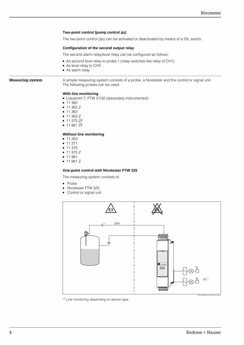
One-point control with Nivotester FTW 325
The measuring system consists of:
• Probe • Nivotester FTW 325 • Control or signal unit
L00-FTW325xx-04-06-xx-xx-001
*1 Line monitoring depending on sensor type
CH1
4 5 6 174 5 6 17
FTW 325
7 8 9 10
EX EX
( )
*1
*1
Nivotester
Endress + Hauser 5
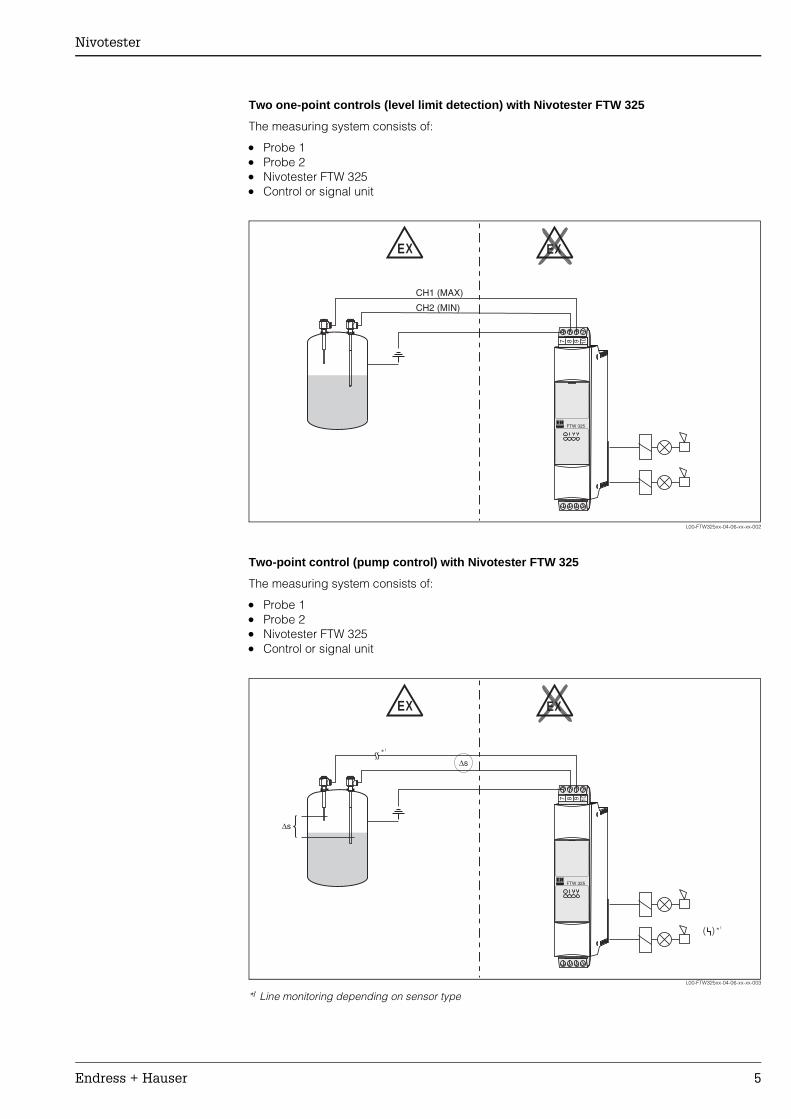
Two one-point controls (level limit detection) with Nivotester FTW 325
The measuring system consists of:
• Probe 1 • Probe 2 • Nivotester FTW 325 • Control or signal unit
L00-FTW325xx-04-06-xx-xx-002
Two-point control (pump control) with Nivotester FTW 325
The measuring system consists of:
• Probe 1 • Probe 2 • Nivotester FTW 325 • Control or signal unit
L00-FTW325xx-04-06-xx-xx-003
*1 Line monitoring depending on sensor type
EX EX
4 5 6 174 5 6 17
FTW 325
7 8 9 10
CH1 (MAX)
CH2 (MIN)
4 5 6 174 5 6 17
FTW 325
7 8 9 10
EX EX
∆s
∆s
( )
*1
*1
Nivotester
6 Endress + Hauser
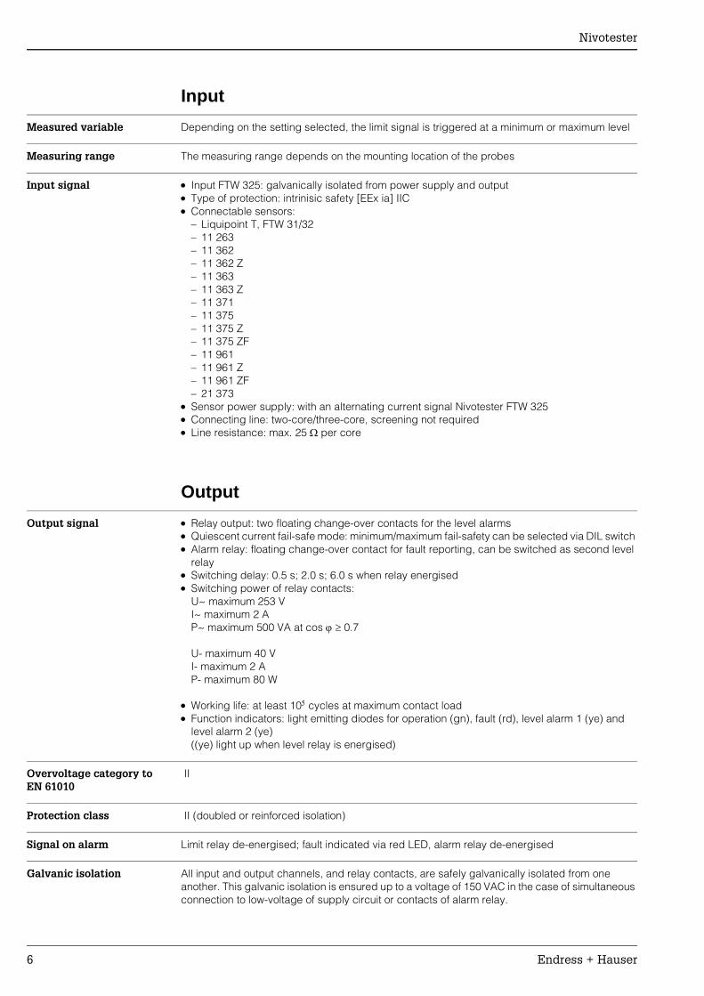
Input
Measured variable Depending on the setting selected, the limit signal is triggered at a minimum or maximum level
Measuring range The measuring range depends on the mounting location of the probes
Input signal • Input FTW 325: galvanically isolated from power supply and output • Type of protection: intrinisic safety [EEx ia] IIC • Connectable sensors:
– Liquipoint T, FTW 31/32 – 11 263 – 11 362 – 11 362 Z – 11 363 – 11 363 Z – 11 371 – 11 375 – 11 375 Z – 11 375 ZF – 11 961 – 11 961 Z – 11 961 ZF – 21 373
• Sensor power supply: with an alternating current signal Nivotester FTW 325 • Connecting line: two-core/three-core, screening not required • Line resistance: max. 25 Ω per core
Output
Output signal • Relay output: two floating change-over contacts for the level alarms • Quiescent current fail-safe mode: minimum/maximum fail-safety can be selected via DIL switch • Alarm relay: floating change-over contact for fault reporting, can be switched as second level
relay • Switching delay: 0.5 s; 2.0 s; 6.0 s when relay energised • Switching power of relay contacts:
U~ maximum 253 V I~ maximum 2 A P~ maximum 500 VA at cos ϕ ≥ 0.7
U- maximum 40 V I- maximum 2 A P- maximum 80 W
• Working life: at least 105 cycles at maximum contact load • Function indicators: light emitting diodes for operation (gn), fault (rd), level alarm 1 (ye) and
level alarm 2 (ye) ((ye) light up when level relay is energised)
Overvoltage category to EN 61010
II
Protection class II (doubled or reinforced isolation)
Signal on alarm Limit relay de-energised; fault indicated via red LED, alarm relay de-energised
Galvanic isolation All input and output channels, and relay contacts, are safely galvanically isolated from one another. This galvanic isolation is ensured up to a voltage of 150 VAC in the case of simultaneous connection to low-voltage of supply circuit or contacts of alarm relay.
Nivotester
Endress + Hauser 7
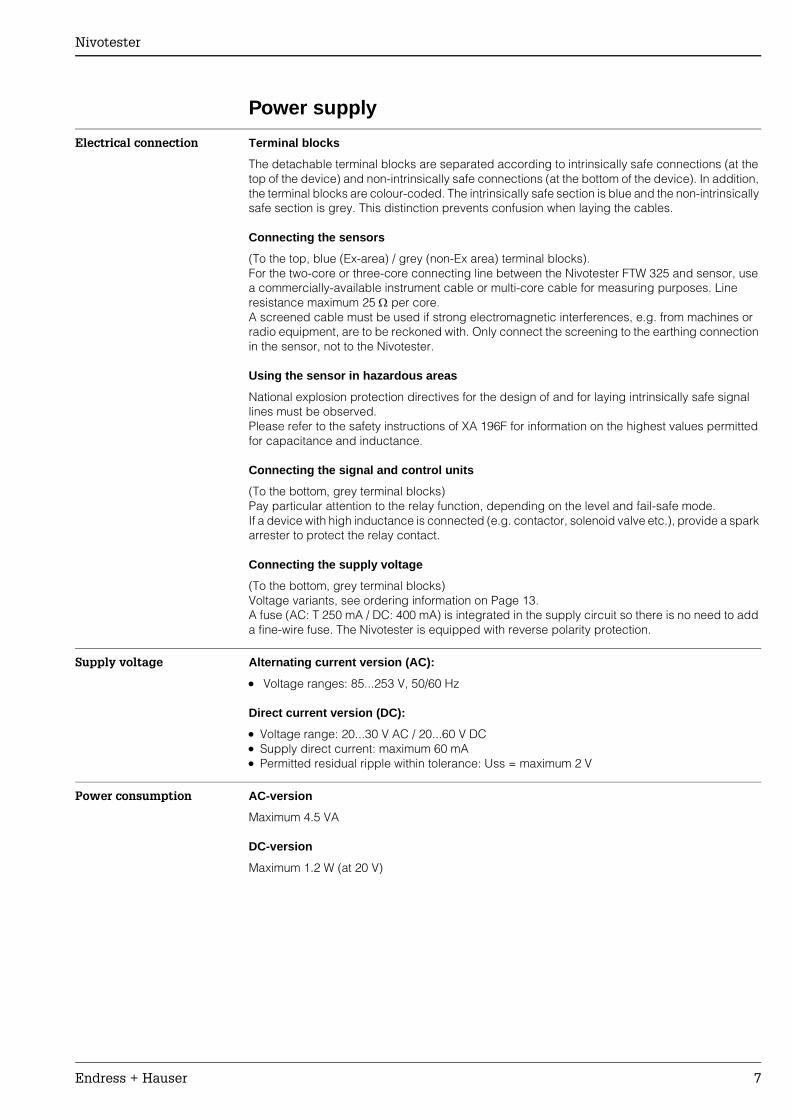
Power supply
Electrical connection Terminal blocks
The detachable terminal blocks are separated according to intrinsically safe connections (at the top of the device) and non-intrinsically safe connections (at the bottom of the device). In addition, the terminal blocks are colour-coded. The intrinsically safe section is blue and the non-intrinsically safe section is grey. This distinction prevents confusion when laying the cables.
Connecting the sensors
(To the top, blue (Ex-area) / grey (non-Ex area) terminal blocks). For the two-core or three-core connecting line between the Nivotester FTW 325 and sensor, use a commercially-available instrument cable or multi-core cable for measuring purposes. Line resistance maximum 25 Ω per core. A screened cable must be used if strong electromagnetic interferences, e.g. from machines or radio equipment, are to be reckoned with. Only connect the screening to the earthing connection in the sensor, not to the Nivotester.
Using the sensor in hazardous areas
National explosion protection directives for the design of and for laying intrinsically safe signal lines must be observed. Please refer to the safety instructions of XA 196F for information on the highest values permitted for capacitance and inductance.
Connecting the signal and control units
(To the bottom, grey terminal blocks) Pay particular attention to the relay function, depending on the level and fail-safe mode. If a device with high inductance is connected (e.g. contactor, solenoid valve etc.), provide a spark arrester to protect the relay contact.
Connecting the supply voltage
(To the bottom, grey terminal blocks) Voltage variants, see ordering information on Page 13. A fuse (AC: T 250 mA / DC: 400 mA) is integrated in the supply circuit so there is no need to add a fine-wire fuse. The Nivotester is equipped with reverse polarity protection.
Supply voltage Alternating current version (AC):
• Voltage ranges: 85...253 V, 50/60 Hz
Direct current version (DC):
• Voltage range: 20...30 V AC / 20...60 V DC• Supply direct current: maximum 60 mA • Permitted residual ripple within tolerance: Uss = maximum 2 V
Power consumption AC-version
Maximum 4.5 VA
DC-version
Maximum 1.2 W (at 20 V)
Nivotester
8 Endress + Hauser
Operating conditions (installation)
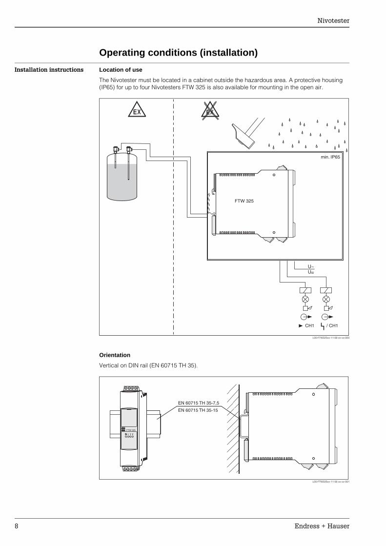
Installation instructions Location of use
The Nivotester must be located in a cabinet outside the hazardous area. A protective housing (IP65) for up to four Nivotesters FTW 325 is also available for mounting in the open air.
L00-FTW325xx-11-06-xx-xx-000
Orientation
Vertical on DIN rail (EN 60715 TH 35).
L00-FTW325xx-11-06-xx-xx-001
EX EX
U~U–~
FTW 325
CH1 / CH1
min. IP65
EN 60715 35-7,5TH
EN 60715 35-15TH
FTW 325FTW 325
Nivotester
Endress + Hauser 9
Operating conditions (environment)
Location of use Cabinet or protective housing
Permitted ambient temperatures
For individual mounting
• –20 °C...+60 °C
For series mounting without lateral spacing
• –20 °C...+50 °C
Storage temperature
• –25 °C...+85 °C (preferably at +20 °C)
Installation in protective housing
• –20 °C...+40 °C • A maximum of four Nivotesters may be installed in a protective housing
" Caution! The devices should be mounted in areas which are protected from weather conditions and impact and, if possible, which are not exposed to direct sunlight. This factor should be observed particularly in warm climates.
Climatic and mechanical application class
3K3 In accordance with DIN EN 60721-3-3
3M2 In accordance with DIN EN 60721-3-3
Degree of protection IP20
Electromagnetic compatibility (EMC)
Interference emission to EN 61326; Electrical equipment Class BInterference immunity to EN 61326; Annex A (industrial) and NAMUR Recommendation NE 21 (EMC)
Nivotester
10 Endress + Hauser
Mechanical construction
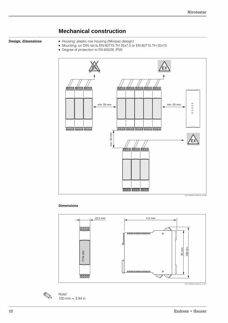
Design, dimensions • Housing: plastic row housing (Minipac-design) • Mounting: on DIN rail to EN 60715 TH 35x7.5 or EN 60715 TH 35x15 • Degree of protection to EN 60529; IP20
L00-FTW325xx-06-06-xx-xx-000
Dimensions
L00-FTW325xx-06-06-xx-xx-001
! Note! 100 mm = 3.94 in
min. 50 mm
min
.50
mm
min. 50 mm
? ?
? ?
?
EX
EX
EX
22,5 mm 112 mm
95 m
m
108
mm
FT
W 3
25
Nivotester
Endress + Hauser 11
Weight Approx. 145 g
Material Housing
• Polycarbonate Colour: light-grey, RAL 7035
Front cover
• Polypropylene PPN Colour: blue
Locating slide (for securing on DIN rail)
• Polyamide PA6 Colour: black, RAL 9005
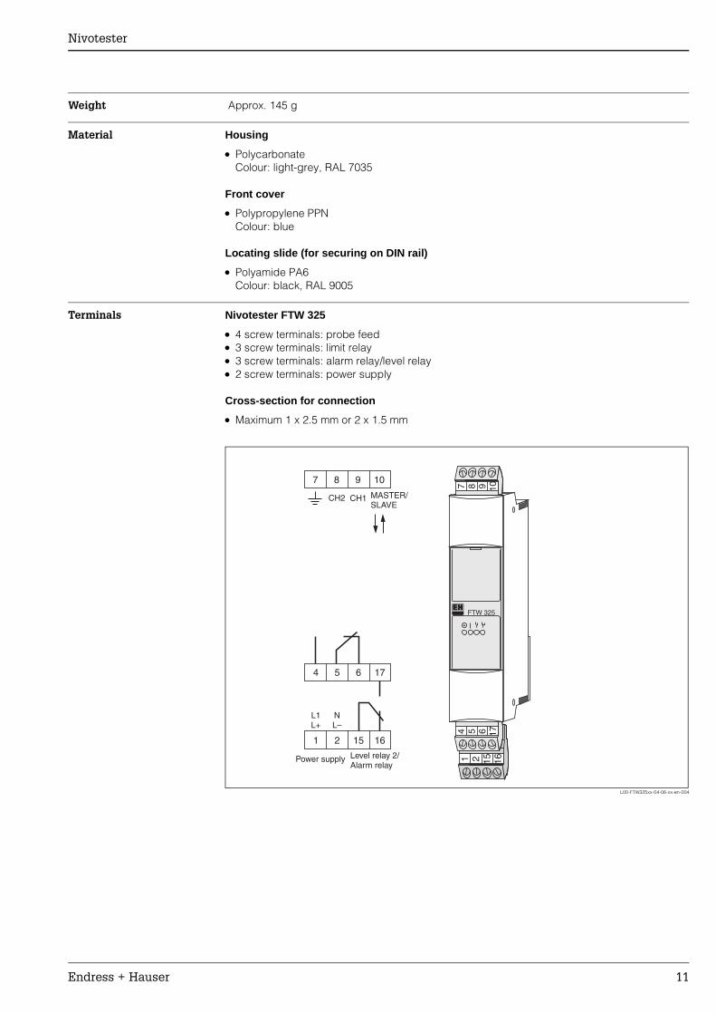
Terminals Nivotester FTW 325
• 4 screw terminals: probe feed • 3 screw terminals: limit relay • 3 screw terminals: alarm relay/level relay • 2 screw terminals: power supply
Cross-section for connection
• Maximum 1 x 2.5 mm or 2 x 1.5 mm
L00-FTW325xx-04-06-xx-en-004
1 2 15 16
4 5 6 17CH2 MASTER/
SLAVECH1
7 8 9 10
FTW 325
7 8 9 10
L1L+
NL–
4 5 6 17
1 2 15 16
Level relay 2/Alarm relay
Power supply
Nivotester
12 Endress + Hauser
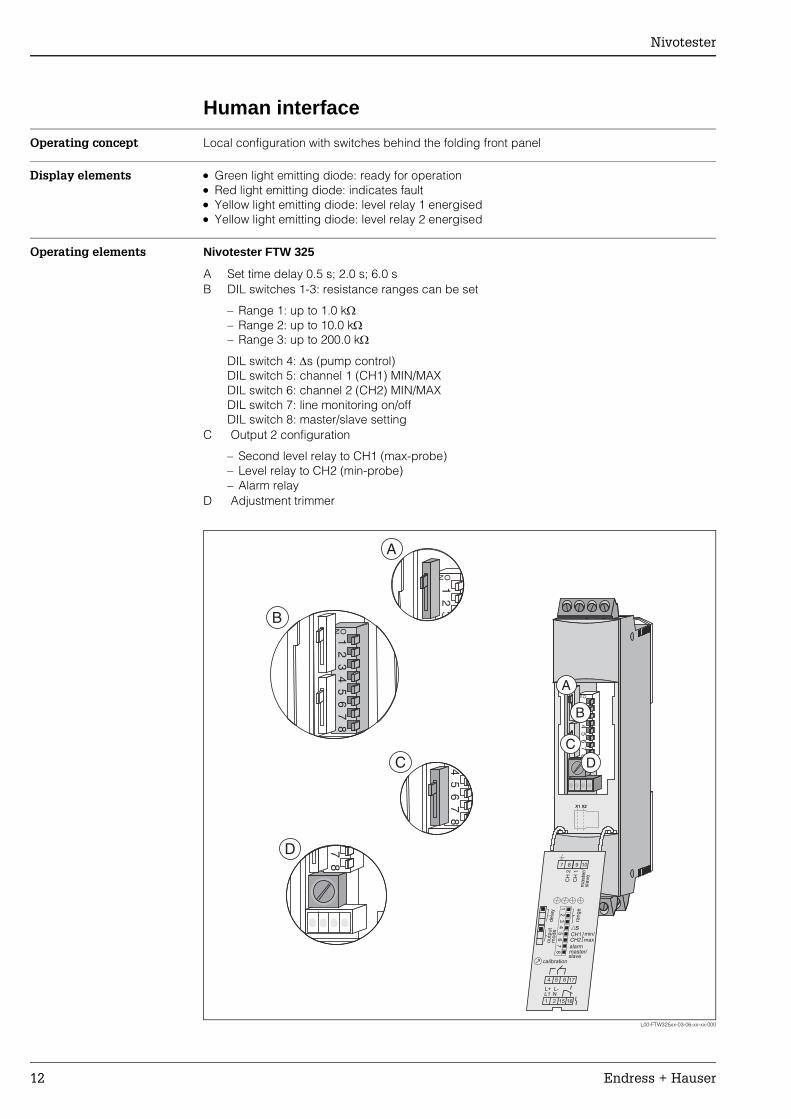
Human interface
Operating concept Local configuration with switches behind the folding front panel
Display elements • Green light emitting diode: ready for operation • Red light emitting diode: indicates fault • Yellow light emitting diode: level relay 1 energised • Yellow light emitting diode: level relay 2 energised
Operating elements Nivotester FTW 325
L00-FTW325xx-03-06-xx-xx-000
A Set time delay 0.5 s; 2.0 s; 6.0 s B DIL switches 1-3: resistance ranges can be set
– Range 1: up to 1.0 kΩ – Range 2: up to 10.0 kΩ – Range 3: up to 200.0 kΩ
DIL switch 4: ∆s (pump control) DIL switch 5: channel 1 (CH1) MIN/MAX DIL switch 6: channel 2 (CH2) MIN/MAX DIL switch 7: line monitoring on/off DIL switch 8: master/slave setting
C Output 2 configuration
– Second level relay to CH1 (max-probe) – Level relay to CH2 (min-probe) – Alarm relay
D Adjustment trimmer
1 2 3 4 5 6 7 8ON
X2X1X1 X2
D
A
B
C
7 8
4 5 6
15 16
L1 NL+ L-
1 2
9 10
CH
2
CH
1m
aste
r/sla
ve
outp
ut
mode
dela
y
s
alarmmaster/slave
range
12
34
56
78
calibration
CH1CH2
17
min/max
1 2ON
A
1 2 3 4 5 6 7 8ON
B
C 4 5 6 7 8
7 8
D
Nivotester
Endress + Hauser 13
Certificates and approvals
CE approval The Nivotester is in conformity with the statutory requirements of the EC Directives. Endress+Hauser confirms successful testing of the device by affixing the CE mark.
Ex approval Information about currently available Ex versions (ATEX EEx ia IIC, FM IS, CSA IS) can be supplied by your E+H Sales Centre on request. All explosion protection data are given in a separate documentation (see: Documentation) which is available upon request.
Type of protection [EEx ia] IIC
Overspill protection WHG
Other standards and guidelines
Other standards and guidelines which were observed when designing and developing the Nivotester FTW 325.
• EN 60529 Degrees of protection by housing (IP code)
• EN 61010 Protection measures for electrical equipment for measurement, control, regulation and laboratory procedures
• EN 61326 Interference emission (electrical equipment Class B), interference immunity (annex A - industrial)
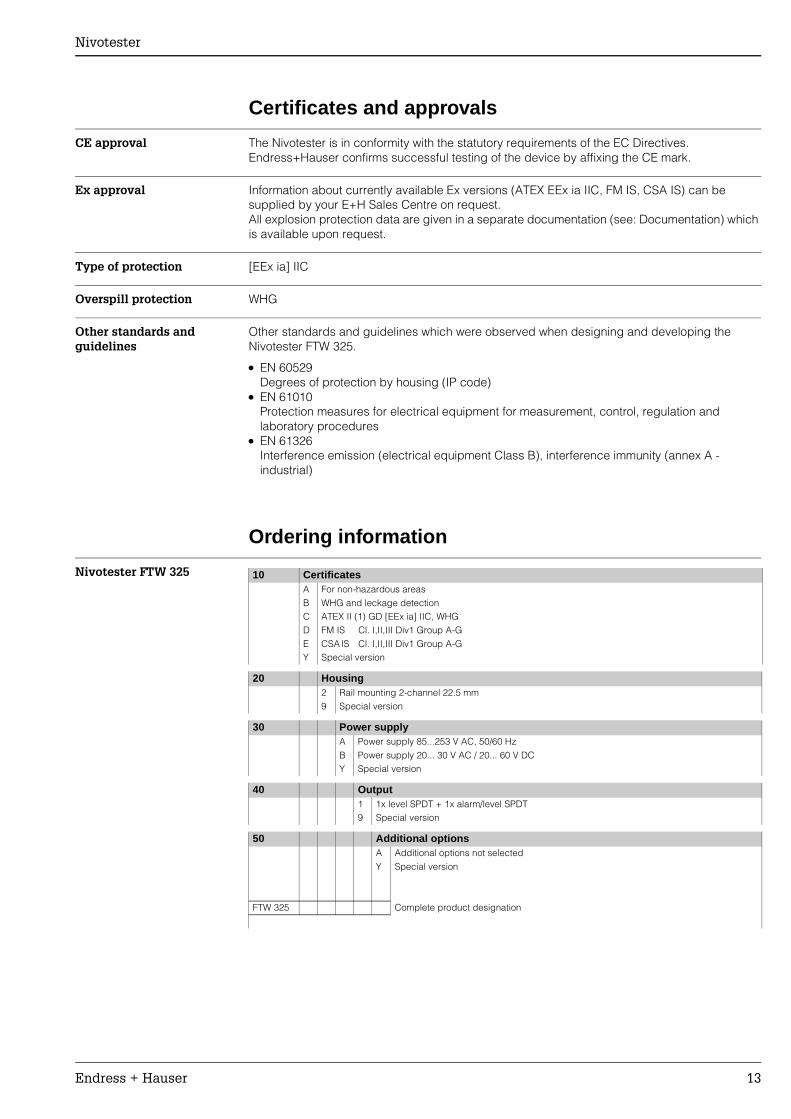
Ordering information
Nivotester FTW 325 10 Certificates A For non-hazardous areas B WHG and leckage detection C ATEX II (1) GD [EEx ia] IIC, WHG D FM IS Cl. I,II,III Div1 Group A-G E CSA IS Cl. I,II,III Div1 Group A-G Y Special version
20 Housing 2 Rail mounting 2-channel 22.5 mm 9 Special version
30 Power supplyA Power supply 85...253 V AC, 50/60 Hz B Power supply 20... 30 V AC / 20... 60 V DC Y Special version
40 Output 1 1x level SPDT + 1x alarm/level SPDT 9 Special version
50 Additional optionsA Additional options not selectedY Special version
FTW 325 Complete product designation
Nivotester
14 Endress + Hauser
Accessories
Protective housing The protective housing of protection class IP 66 is equipped with an integrated DIN rail and is closed with a transparent cover which can be lead-sealed.
Dimensions:
W: 180 / H: 182 / D: 165
Colour:
Light-grey RAL 7035 Part number: 52010132
Documentation
Technical Information(TI)
Conductive level probes
• Liquipoint T, FTW 31/32 TI 375F/00
• 11263 TI 323F/00
• 11362,11362 Z TI 131F/00
• 11363, 11363 Z TI 122F/00
• 11371 TI 276F/00
• 11375, 11375 Z, 11375 ZF TI 298F/00
• 11961, 11961 Z, 11961 ZF TI 325F/00
Line monitoring
• EW 11 Z BA 145F/00/a2
Protective Housing
• TI 367F/00
Operating Instructions (KA)
• Nivotester FTW 325 KA 199F/00
• Liquipoint T Separately instrumented KA 203F/00
• Liquipoint T Compactly instrumented KA 204F/00
Nivotester
Endress + Hauser 15
Certificates ATEX:
• Nivotester XA 196F/00
DIBT:
• NivotesterZE 043F/00
• Liquipoint TZE 257F/00
Nivotester
Endress+Hauser GmbH+Co.Instruments InternationalP.O. Box 2222D-79574 Weil am RheinGermany
Tel. (07621) 975-02Tx 773926Fax (07621) 975 345e-mail: [email protected]
Internet:http://www.endress.com
11.01
TI 373F/00/en/12.03 SL /FM+SGML 6.0 ProMoDo