technical Information Nivotester Ftc325fotonika.kiev.ua/pdf/FTC325.pdf · TI380F/00/EN/05.10...
20
TI380F/00/EN/05.10 71115361 Technical Information Nivotester FTC325 Level limit switch With Intrinsically Safe Signal Circuit for Connection to a Capacitance Sensor Applications • Level limit detection in tanks containing liquids and silos containing bulk solids. For capacitance level probes, which may also be applied in hazardous areas of category ATEX II (1) GD • Overspill protection for tanks containing flammable or non-flammable fluids hazardous to water • Dry running protection for pumps • Two-point control (Δs with 3-WIRE) Your benefits • Intrinsically safe signal circuit [EEx ia] IIC for using sensors in hazardous areas • Calibration using operating keys • High functional safety thanks to: – fail-safe pulse-frequency modulation (PFM) or 3-WIRE technology – Checkable relay function • Compact housing for easy series mounting on a standard DIN rail in the cabinet • Pluggable terminal blocks make wiring easy • Can be used with FEI57S (PFM), EC16Z (PFM), EC17Z (PFM), FEI53 (3-WIRE) and EC61 (3-WIRE) • Limit value and alarm relay • WHG approval (PFM) • Protection against maloperation and manipulation – each change of the device configuration leads to signalling via the red LED and a fault message
Transcript of technical Information Nivotester Ftc325fotonika.kiev.ua/pdf/FTC325.pdf · TI380F/00/EN/05.10...

TI380F/00/EN/05.10
71115361
Technical Information
Nivotester FTC325
Level limit switch
With Intrinsically Safe Signal Circuit for Connection
to a Capacitance Sensor
Applications
• Level limit detection in tanks containing liquids and
silos containing bulk solids. For capacitance level
probes, which may also be applied in hazardous areas
of category ATEX II (1) GD
• Overspill protection for tanks containing flammable or
non-flammable fluids hazardous to water
• Dry running protection for pumps
• Two-point control (Δs with 3-WIRE)
Your benefits
• Intrinsically safe signal circuit [EEx ia] IIC for using
sensors in hazardous areas
• Calibration using operating keys
• High functional safety thanks to:
– fail-safe pulse-frequency modulation (PFM) or
3-WIRE technology
– Checkable relay function
• Compact housing for easy series mounting on a
standard DIN rail in the cabinet
• Pluggable terminal blocks make wiring easy
• Can be used with FEI57S (PFM), EC16Z (PFM),
EC17Z (PFM), FEI53 (3-WIRE) and EC61 (3-WIRE)
• Limit value and alarm relay
• WHG approval (PFM)
• Protection against maloperation and manipulation
– each change of the device configuration leads to
signalling via the red LED and a fault message
Nivotester FTC325
2 Endress+Hauser
Table of contents
Function and system design. . . . . . . . . . . . . . . . . . . . . 3
Measuring principle . . . . . . . . . . . . . . . . . . . . . . . . . . . . . . . . . . . 3
Measuring device . . . . . . . . . . . . . . . . . . . . . . . . . . . . . . . . . . . . . 5
Input parameters . . . . . . . . . . . . . . . . . . . . . . . . . . . . . 8
Measured variable . . . . . . . . . . . . . . . . . . . . . . . . . . . . . . . . . . . . 8
Measuring range . . . . . . . . . . . . . . . . . . . . . . . . . . . . . . . . . . . . . . 8
Input signal . . . . . . . . . . . . . . . . . . . . . . . . . . . . . . . . . . . . . . . . . 8
Output parameters. . . . . . . . . . . . . . . . . . . . . . . . . . . . 9
Output signal . . . . . . . . . . . . . . . . . . . . . . . . . . . . . . . . . . . . . . . . 9
Signal on alarm . . . . . . . . . . . . . . . . . . . . . . . . . . . . . . . . . . . . . . 9
Galvanic isolation . . . . . . . . . . . . . . . . . . . . . . . . . . . . . . . . . . . . . 9
Overvoltage category as per EN 61010 . . . . . . . . . . . . . . . . . . . . . 9
Protection class . . . . . . . . . . . . . . . . . . . . . . . . . . . . . . . . . . . . . . 9
Power supply. . . . . . . . . . . . . . . . . . . . . . . . . . . . . . . 10
Electrical connection . . . . . . . . . . . . . . . . . . . . . . . . . . . . . . . . . 10
Supply voltage . . . . . . . . . . . . . . . . . . . . . . . . . . . . . . . . . . . . . . 10
Power consumption . . . . . . . . . . . . . . . . . . . . . . . . . . . . . . . . . . 10
Operating conditions (installation conditions) . . . . . . 11
Installation instructions . . . . . . . . . . . . . . . . . . . . . . . . . . . . . . . . 11
Operating conditions (environmental conditions) . . . 12
Installation location . . . . . . . . . . . . . . . . . . . . . . . . . . . . . . . . . . 12
Permitted ambient temperatures . . . . . . . . . . . . . . . . . . . . . . . . . 12
Climatic and mechanical application class . . . . . . . . . . . . . . . . . 12
Degree of protection . . . . . . . . . . . . . . . . . . . . . . . . . . . . . . . . . . 12
Electromagnetic compatibility (EMC) . . . . . . . . . . . . . . . . . . . . . 12
Mechanical construction . . . . . . . . . . . . . . . . . . . . . . 13
Design, dimensions . . . . . . . . . . . . . . . . . . . . . . . . . . . . . . . . . . 13
Weight . . . . . . . . . . . . . . . . . . . . . . . . . . . . . . . . . . . . . . . . . . . . 14
Materials . . . . . . . . . . . . . . . . . . . . . . . . . . . . . . . . . . . . . . . . . . 14
Terminals . . . . . . . . . . . . . . . . . . . . . . . . . . . . . . . . . . . . . . . . . . 14
User interface . . . . . . . . . . . . . . . . . . . . . . . . . . . . . . 15
Display elements . . . . . . . . . . . . . . . . . . . . . . . . . . . . . . . . . . . . 15
Operating elements . . . . . . . . . . . . . . . . . . . . . . . . . . . . . . . . . . 15
Operating elements . . . . . . . . . . . . . . . . . . . . . . . . . . . . . . . . . . 16
Certificates and approvals . . . . . . . . . . . . . . . . . . . . . 17
CEmark . . . . . . . . . . . . . . . . . . . . . . . . . . . . . . . . . . . . . . . . . . . 17
Ex approval . . . . . . . . . . . . . . . . . . . . . . . . . . . . . . . . . . . . . . . . 17
Type of protection . . . . . . . . . . . . . . . . . . . . . . . . . . . . . . . . . . . 17
Overspill protection . . . . . . . . . . . . . . . . . . . . . . . . . . . . . . . . . . 17
Other standards and regulations . . . . . . . . . . . . . . . . . . . . . . . . . 17
Ordering information. . . . . . . . . . . . . . . . . . . . . . . . . 18
Nivotester FTC325 PFM . . . . . . . . . . . . . . . . . . . . . . . . . . . . . . . 18
Nivotester FTC325 3-WIRE . . . . . . . . . . . . . . . . . . . . . . . . . . . . 18
Accessories . . . . . . . . . . . . . . . . . . . . . . . . . . . . . . . . 19
Protective housing . . . . . . . . . . . . . . . . . . . . . . . . . . . . . . . . . . . 19
Supplementary Documentation . . . . . . . . . . . . . . . . . 19
System Information (SI) . . . . . . . . . . . . . . . . . . . . . . . . . . . . . . . 19
Technical Information (TI) . . . . . . . . . . . . . . . . . . . . . . . . . . . . . 19
Operating manual (KA) . . . . . . . . . . . . . . . . . . . . . . . . . . . . . . . 19
Certificates (only for PFM) . . . . . . . . . . . . . . . . . . . . . . . . . . . . . 19
Nivotester FTC325
Endress+Hauser 3
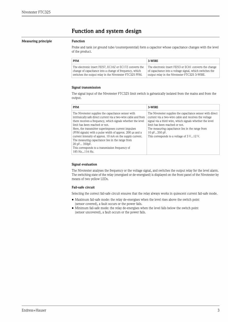
Function and system design
Measuring principle Function
Probe and tank (or ground tube/counterpotential) form a capacitor whose capacitance changes with the level
of the product.
Signal transmission
The signal input of the Nivotester FTC325 limit switch is galvanically isolated from the mains and from the
output.
Signal evaluation
The Nivotester analyses the frequency or the voltage signal, and switches the output relay for the level alarm.
The switching state of the relay (energised or de-energised) is displayed on the front panel of the Nivotester by
means of two yellow LEDs.
Fail-safe circuit
Selecting the correct fail-safe circuit ensures that the relay always works in quiescent current fail-safe mode.
• Maximum fail-safe mode: the relay de-energises when the level rises above the switch point
(sensor covered), a fault occurs or the power fails.
• Minimum fail-safe mode: the relay de-energises when the level falls below the switch point
(sensor uncovered), a fault occurs or the power fails.
PFM 3-WIRE
The electronic insert FEI57, EC16Z or EC17Z converts the
change of capacitance into a change of frequency, which
switches the output relay in the Nivotester FTC325 PFM.
The electronic insert FEI53 or EC61 converts the change
of capacitance into a voltage signal, which switches the
output relay in the Nivotester FTC325 3-WIRE.
PFM 3-WIRE
The Nivotester supplies the capacitance sensor with
intrinsically safe direct current via a two-wire cable and from
there receives a frequency, which signals whether the level
limit has been reached or not.
Here, the transmitter superimposes current impulses
(PFM signals) with a pulse width of approx. 200 μs and a
current intensity of approx. 10 mA on the supply current.
The measuring capacitance lies in the range from
20 pF... 350pF.
This corresponds to a transmission frequency of
185 Hz...116 Hz.
The Nivotester supplies the capacitance sensor with direct
current via a two-wire cable and receives the voltage
signal via a third wire, which signals whether the level
limit has been reached or not.
The measuring capacitance lies in the range from
10 pF...350 pF.
This corresponds to a voltage of 3 V...12 V.

Nivotester FTC325
4 Endress+Hauser
PFM
L00-FTC325xx-15-06-xx-en-001
Function of the limit indicator dependent on the level and fail-safe circuit.
3-WIRE
L00-FTC325xx-15-06-xx-en-002
Function of the limit indicator dependent on the level and fail-safe circuit.
15 16
15 1622 23 24
22 23 24
22 23 24
22 23 2415 16
15 16
CH1
CH1 CH1
CH1
NO
NO
NC NO
NC NO
NC
NC
15 16
15 16
NO
NO
15 16
15 16
Probeuncovered
Probecovered
Level
Maximumsafety circuit
Minimumsafety circuit
4 5 6 4 5 6
CH1 CH1
17 15 16
4 5 6
CH1
17 15 16
17 15 16
4 5 6
CH1
17 15 16
Probeuncovered
Probecovered
Level
Maximumsafety circuit
Minimumsafety circuit

Nivotester FTC325
Endress+Hauser 5
Function monitoring
To increase operational safety the Nivotester is equipped with a function monitoring facility.
A fault is displayed by the red light emitting diode and de-energises the relay for the level alarm and the alarm
relay. A fault is reported if the Nivotester is no longer receiving a measuring signal. This occurs, for example,
when:
• there is a short-circuit
• the signal line to the sensor is interrupted
• the sensor electronics are defective
• the Nivotester's input switching is defective
After calibration, every further change to the device configuration de-energises the relay.
A fault message is signalled via the red LED.
Calibration key (red)
Calibration is carried out automatically by means of operating keys. This makes setting via rotary switches
inapplicable.
The test/correction key (green - FTC325 PFM only):
• allows for a function check of the output relay and alarm relay.
• confirms a change in the operating mode - e.g. by changing the switching delay after initial calibration.
This enables a correction of the operating mode without requiring recalibration. The changed settings are
saved by pressing the operating key.
Additional switch functions
• An adjustable switching delay of 0...45 s allows for the relay to be switched with a delay when covering or
uncovering the probe. In the opposite direction, each switching delay is 0.2 s.
• Τwo-point control (Δs function, FTC325 3-WIRE), see page 7
• A potentiometer (rotary switch) for shifting the operating point allows safe operation of the system, even with
media that are prone to build-up.
Measuring device A simple measuring system consists of a capacitance sensor, a Nivotester FTC325 and the control or signal
instruments.
The following sensors can be used in conjunction with the electronic inserts (EC) listed.
* Phase-out: 2007, ** Phase-out: 2008, *** Phase-out: 2009
FTC325 PFM FTC325 3-WIRE
Liquicap M FTI51, FTI52 with FEI57S FEI53
Solicap M FTI55, FTI56 with FEI57S FEI53
Solicap S FTI77 with FEI57S FEI53
Solicap FTC51*, FTC52*, FTC53* with EC17Z EC61
Multicap T* with EC17Z EC61
Multicap Classic* with EC16Z, EC17Z EC61
Multicap EA* with EC17Z
High-temperature probes T12656***, T12892*** with EC17Z EC61
High-temperature probe 11500** with EC17Z
Double rod probe 11304** with EC17Z

Nivotester FTC325
6 Endress+Hauser
Probe construction
Level limit detection with FTC325 PFM
L00-FTC625xx-05-06-xx-en-000
Nivotester FTC325 PFM Nivotester FTC325 3-WIRE
The measuring system consists of:
• Sensor
– capacitance probe
– electronic insert
– FEI57S, EC16Z, EC17Z
• Nivotester FTC325 PFM
• Control or signal instruments
The measuring system consists of:
• Sensor
– one or two capacitance probes
– electronic insert
– FEI53, EC61
• Nivotester FTC325 3-WIRE
• Control or signal instruments
L00-FTC325xx-14-06-xx-xx-001
Partially or fully insulated probe
–
–
–
–
–
–
–
–
–
< 3
εr
< 3
> 3
> 3
> 3Sludge
Aqueous liquidsand alcohols
Moist bulk solids
Dry bulk solids
Solvents, fuels low
Conductivity Build-up Type of probe mounting
fullinsulation
partialinsulation
withground tube
withoutground tube
Example: Material
low
low low
average average
stronglow
strong
strong very strong
U
CH1
FTC325 T

Nivotester FTC325
Endress+Hauser 7
Level limit detection with FTC325 3-WIRE
L00-FTC325xx-14-06-xx-xx-002
Partially or fully insulated probe
L00-FTC325xx-14-06-xx-xx-004
Two-point control with fully insulated probe
L00-FTC325xx-14-06-xx-en-001
Two-point control with two fully or partially insulated probes and an electronic insert EC61 resp. FEI53.
The probes are connected by a coaxial cable.
U
CH1
3-WIREFTC325
MAX
MIN
3-WIREFTC325
Δs
U
CH1
CH1
3-WIREFTC325
1 2
EC61
1 2 3 4 5 6
�s
U
FEI53 /EC61
1
2
Coaxial cable
Nivotester FTC325
8 Endress+Hauser
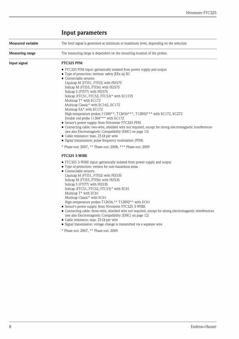
Input parameters
Measured variable The limit signal is generated at minimum or maximum level, depending on the selection
Measuring range The measuring range is dependent on the mounting location of the probes.
Input signal FTC325 PFM
• FTC325 PFM input: galvanically isolated from power supply and output
• Type of protection: intrinsic safety [EEx ia] IIC
• Connectable sensors:
Liquicap M (FTI51, FTI52) with FEI57S
Solicap M (FTI55, FTI56) with FEI57S
Solicap S (FTI77) with FEI57S
Solicap (FTC51, FTC52, FTC53)* with EC17ZS
Multicap T* with EC17Z
Multicap Classic* with EC16Z, EC17Z
Multicap EA* with EC17Z
High-temperature probes 11500**, T12656***, T12892*** with EC17Z, EC27Z
Double rod probe 11304*** with EC17Z
• Sensor's power supply: from Nivotester FTC325 PFM
• Connecting cable: two-wire, shielded wire not required, except for strong electromagnetic interferences
(see also Electromagnetic Compatibility (EMC) on page 12)
• Cable resistance: max. 25 Ω per wire
• Signal transmission: pulse-frequency modulation (PFM)
* Phase-out: 2007, ** Phase-out: 2008, *** Phase-out: 2009
FTC325 3-WIRE
• FTC325 3-WIRE input: galvanically isolated from power supply and output
• Type of protection: version for non-hazardous areas
• Connectable sensors:
Liquicap M (FTI51, FTI52) with FEI53S
Solicap M (FTI55, FTI56) with FEI53S
Solicap S (FTI77) with FEI53S
Solicap (FTC51, FTC52, FTC53)* with EC61
Multicap T* with EC61
Multicap Classic* with EC61
High-temperature probes T12656,** T12892** with EC61
• Sensor's power supply: from Nivotester FTC325 3-WIRE
• Connecting cable: three-wire, shielded wire not required, except for strong electromagnetic interferences
(see also Electromagnetic Compatibility (EMC) on page 12)
• Cable resistance: max. 25 Ω per wire
• Signal transmission: voltage change is transmitted via a separate wire
* Phase-out: 2007, ** Phase-out: 2009
Nivotester FTC325
Endress+Hauser 9
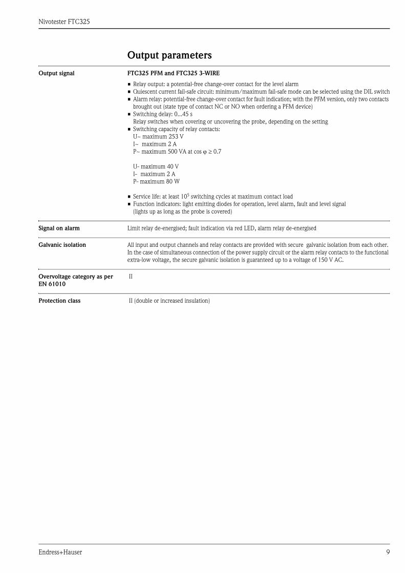
Output parameters
Output signal FTC325 PFM and FTC325 3-WIRE
• Relay output: a potential-free change-over contact for the level alarm
• Quiescent current fail-safe circuit: minimum/maximum fail-safe mode can be selected using the DIL switch
• Alarm relay: potential-free change-over contact for fault indication; with the PFM version, only two contacts
brought out (state type of contact NC or NO when ordering a PFM device)
• Switching delay: 0...45 s
Relay switches when covering or uncovering the probe, depending on the setting
• Switching capacity of relay contacts:
U~ maximum 253 V
I~ maximum 2 A
P~ maximum 500 VA at cos ϕ ≥ 0.7
U- maximum 40 V
I- maximum 2 A
P- maximum 80 W
• Service life: at least 105 switching cycles at maximum contact load
• Function indicators: light emitting diodes for operation, level alarm, fault and level signal
(lights up as long as the probe is covered)
Signal on alarm Limit relay de-energised; fault indication via red LED, alarm relay de-energised
Galvanic isolation All input and output channels and relay contacts are provided with secure galvanic isolation from each other.
In the case of simultaneous connection of the power supply circuit or the alarm relay contacts to the functional
extra-low voltage, the secure galvanic isolation is guaranteed up to a voltage of 150 V AC.
Overvoltage category as per
EN 61010
II
Protection class II (double or increased insulation)
Nivotester FTC325
10 Endress+Hauser
Power supply
Electrical connection Terminal blocks
The removable terminal blocks are isolated after intrinsically safe connections (top of device) and non-
intrinsically safe connections (bottom of device). Furthermore, the terminal blocks are also colour-coded.
Blue is for the intrinsically safe area and grey for the non-intrinsically safe area. These distinctions allow for safe
cable routing.
Sensor connection
(To the upper, blue/grey terminal blocks).
Use a usual commercial instrument cable or multi-core cable for measuring purposes for the connecting cable
between the Nivotester FTC325 and the sensor. Cable resistance of maximum 25 Ω per wire.
If strong electromagnetic interferences have to be expected, e.g. from machines or radios, a screened cable
must be used. Only connect the screening to the grounding connection in the sensor, not to the Nivotester.
Use of measuring cell in potentially explosive atmospheres
Compliance with the national explosion protection regulations for the design and laying of intrinsically safe
signal line is mandatory.
High-reliability values for capacitance and inductance are contained in Safety Instructions XA 195F.
Connection of signal and control instruments
(To the lower, grey terminal blocks)
The relay function must be observed dependent on the level and fail-safe circuit.
If a device with high inductance (e.g. contactor, solenoid valve, etc.) is connected, a spark suppressor must be
added to protect the relay contact.
Supply voltage connection
(To the lower, grey terminal blocks)
For the voltage versions, see the Ordering information on page 17.
A fuse (T 200 mA) is built into the power supply circuit, so that it is not necessary to pre-connect a fine-wire
fuse. The Nivotester is equipped with reverse polarity protection.
Supply voltage Alternating current version (AC):
• Voltage ranges: 85...253 V, 50/60 Hz
Direct current version (DC):
• Voltage range: 20...60 V
• Power supply direct current: maximum 100 mA
• Permitted residual ripple within the tolerance: Uss = maximum 2 V
Power consumption AC version
maximum 6.0 VA
DC version
maximum 2.0 W (at Umin 20 V)
Nivotester FTC325
Endress+Hauser 11
Operating conditions (installation conditions)
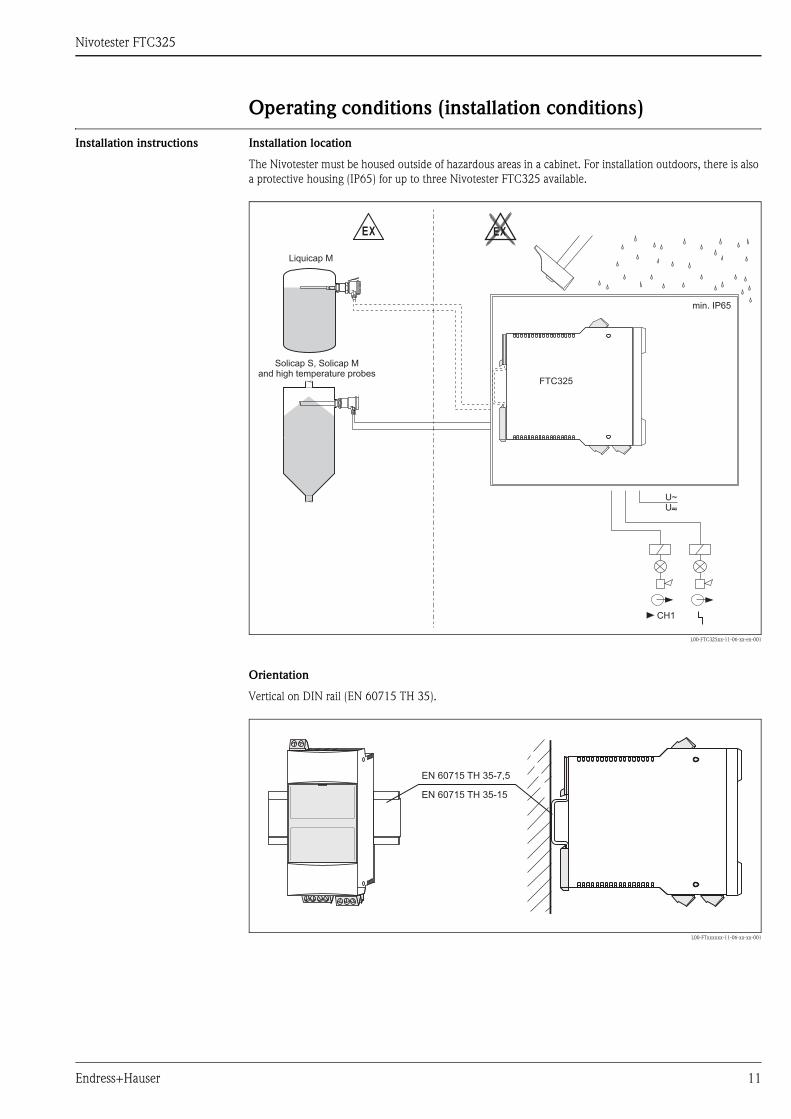
Installation instructions Installation location
The Nivotester must be housed outside of hazardous areas in a cabinet. For installation outdoors, there is also
a protective housing (IP65) for up to three Nivotester FTC325 available.
L00-FTC325xx-11-06-xx-en-001
Orientation
Vertical on DIN rail (EN 60715 TH 35).
L00-FTxxxxxx-11-06-xx-xx-001
EX EX
U~U–~
CH1
FTC325
min. IP65
Solicap S, Solicap Mand high temperature probes
Liquicap M
EN 60715 35-7,5TH
EN 60715 35-15TH
Nivotester FTC325
12 Endress+Hauser
Operating conditions (environmental conditions)
Installation location Cabinet or protective housing
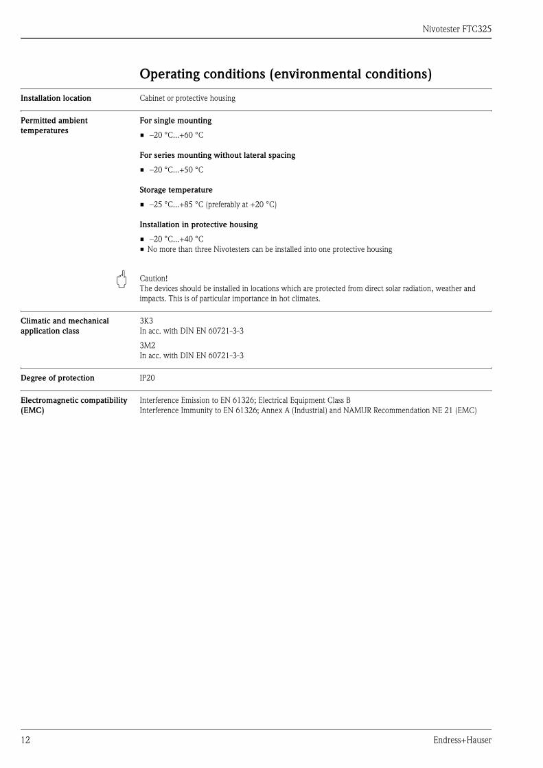
Permitted ambient
temperatures
For single mounting
• –20 °C...+60 °C
For series mounting without lateral spacing
• –20 °C...+50 °C
Storage temperature
• –25 °C...+85 °C (preferably at +20 °C)
Installation in protective housing
• –20 °C...+40 °C
• No more than three Nivotesters can be installed into one protective housing
" Caution!
The devices should be installed in locations which are protected from direct solar radiation, weather and
impacts. This is of particular importance in hot climates.
Climatic and mechanical
application class
3K3
In acc. with DIN EN 60721-3-3
3M2
In acc. with DIN EN 60721-3-3
Degree of protection IP20
Electromagnetic compatibility
(EMC)
Interference Emission to EN 61326; Electrical Equipment Class B
Interference Immunity to EN 61326; Annex A (Industrial) and NAMUR Recommendation NE 21 (EMC)
Nivotester FTC325
Endress+Hauser 13
Mechanical construction
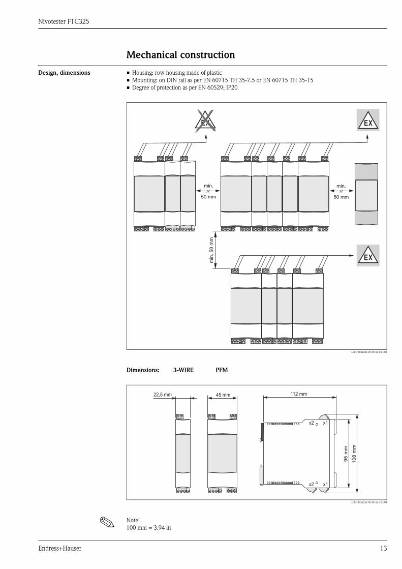
Design, dimensions • Housing: row housing made of plastic
• Mounting: on DIN rail as per EN 60715 TH 35-7.5 or EN 60715 TH 35-15
• Degree of protection as per EN 60529; IP20
L00-FTxxxxxx-06-06-xx-xx-002
Dimensions: 3-WIRE PFM
L00-FTxxxxxx-06-06-xx-xx-004
! Note!
100 mm = 3.94 in
min
.50
mm
min.
50 mm
min.
50 mm
EX
EX
EX
x2
x2
x1
x1
45 mm 112 mm
95
mm
108
mm
22,5 mm
Nivotester FTC325
14 Endress+Hauser
Weight approx. 250 g
Materials Housing
• Polycarbonate
Colour: light grey, RAL 7035
Front cover
• Polypropylene PPN
Colour: blue
Fixing bracket (for securing on the DIN rail)
• Polyamide PA6
Colour: black, RAL 9005
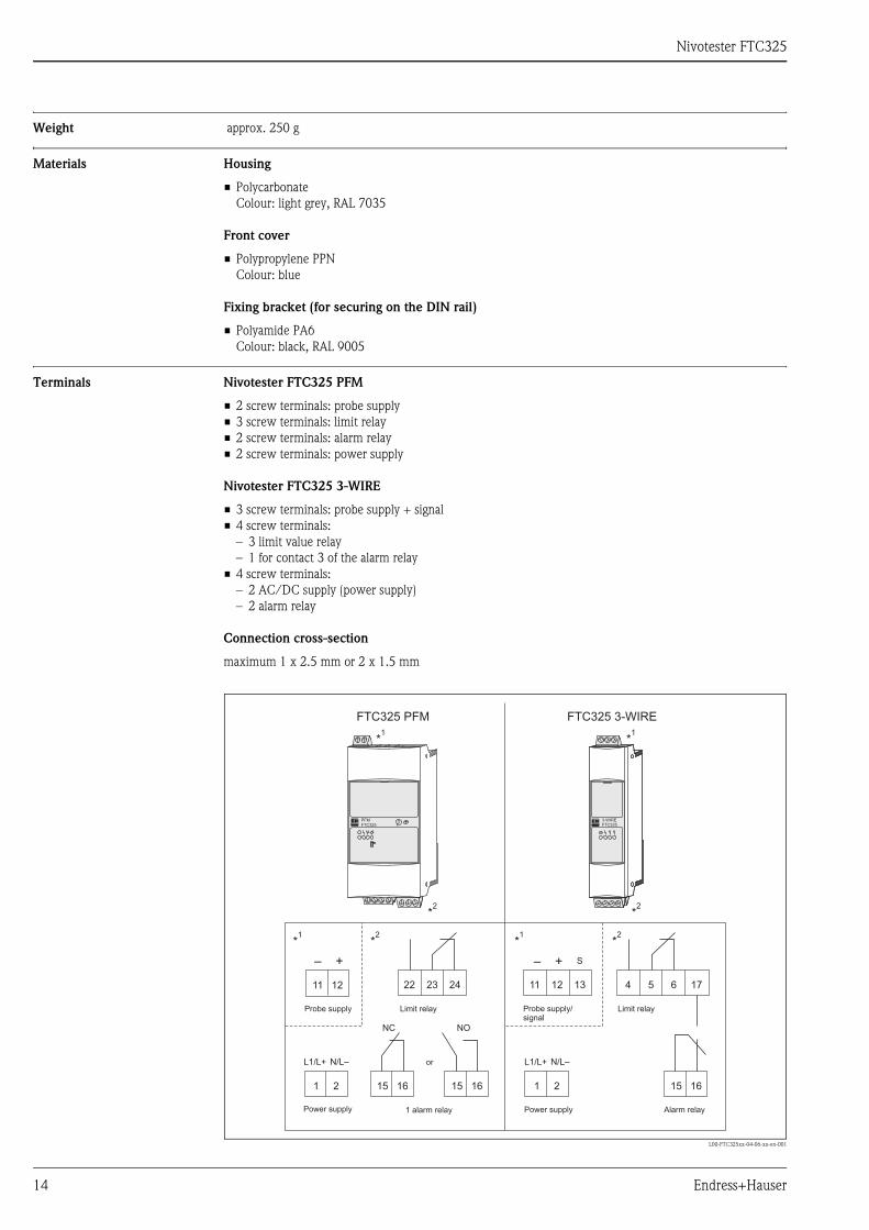
Terminals Nivotester FTC325 PFM
• 2 screw terminals: probe supply
• 3 screw terminals: limit relay
• 2 screw terminals: alarm relay
• 2 screw terminals: power supply
Nivotester FTC325 3-WIRE
• 3 screw terminals: probe supply + signal
• 4 screw terminals:
– 3 limit value relay
– 1 for contact 3 of the alarm relay
• 4 screw terminals:
– 2 AC/DC supply (power supply)
– 2 alarm relay
Connection cross-section
maximum 1 x 2.5 mm or 2 x 1.5 mm
L00-FTC325xx-04-06-xx-en-001
L1/L+ N/L–
– +
11 12 1311 12
15 161 215 16
NC NO
L1/L+ N/L–
15 161 2
4 5 6 1722 23 24
– + S
FTC325 PFM FTC325 3-WIRE
FTW 3253-WIREFTC325
PFMFTC325
T
*1
*1
*2
*2
*1
*1
*2
*2
Probe supply/signal
Limit relay
1 alarm relay Alarm relayPower supply
Limit relayProbe supply
Power supply
or
Nivotester FTC325
Endress+Hauser 15
User interface
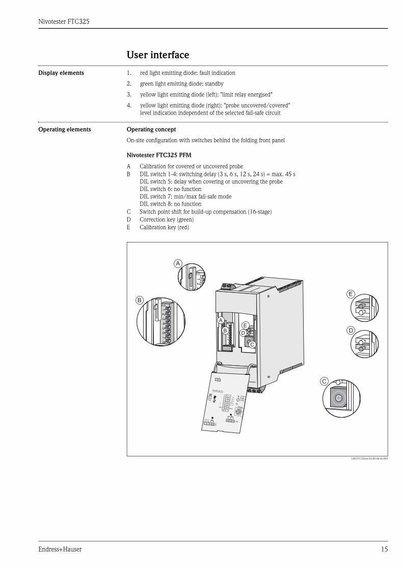
Display elements 1. red light emitting diode: fault indication
2. green light emitting diode: standby
3. yellow light emitting diode (left): "limit relay energised"
4. yellow light emitting diode (right): "probe uncovered/covered"
level indication independent of the selected fail-safe circuit
Operating elements Operating concept
On-site configuration with switches behind the folding front panel
Nivotester FTC325 PFM
L00-FTC325xx-03-06-06-xx-001
A Calibration for covered or uncovered probe
B DIL switch 1-4: switching delay (3 s, 6 s, 12 s, 24 s) = max. 45 s
DIL switch 5: delay when covering or uncovering the probe
DIL switch 6: no function
DIL switch 7: min/max fail-safe mode
DIL switch 8: no function
C Switch point shift for build-up compensation (16-stage)
D Correction key (green)
E Calibration key (red)
12
34
56
78
ON
A
BE
D
C
22 23 24
11 12
CH1
15 16
N
1 2
L1L+ L-
- +
1
2
3
4
5
6
7
8
3 s6 s
12 s24 s
S
MAX
tMIN
T
Offset
2
1
12
ON
A
12
34
56
78
ON
B
C
D
E

Nivotester FTC325
16 Endress+Hauser
Operating elements Nivotester FTC325 3-WIRE
L00-FTC325xx-03-06-06-xx-002
A Calibration for covered or uncovered probe
B DIL switch 1-4: switching delay (3 s, 6 s, 12 s, 24 s) = max. 45 s
DIL switch 5: delay when covering or uncovering the probe
DIL switch 6: min/max fail-safe mode
DIL switch 7: two-point controller mode (ON/OFF)
DIL switch 8: calibration switch point (upper/lower), operation as two-point controller
C Switch point shift for build-up compensation (infinitely variable)
E Calibration key (red)
3362
12
34
56
78
ON
X2X1X1 X2
11
–
4 5 6
15 16
L1 NL+ L-
1 2
12
+
13
s
t s
sss cal_
12
34
56
78
12s24s
6s3s
21
MAXMIN
Offset
T
Off
17
12
3ON
A
A12
34
56
78
ON
B
B
C
3362
78
C
E
1ON
E

Nivotester FTC325
Endress+Hauser 17
Certificates and approvals
CEmark The Nivotester meets all the statutory requirements arising from EC directives.
Endress+Hauser confirms the successful testing of the device by affixing the CE-symbol.
Ex approval Endress+Hauser Sales Centers provide information about the currently available versions for use in hazardous
areas (ATEX EEx ia IIC; FM IS; CSA IS)
All the relevant data for explosion protection is contained in separate Ex documentation
(see: Supplementary Documentation), which can be requested.
Type of protection [EEx ia] IIC (only for FTC325 PFM)
Overspill protection WHG (only for FTC325 PFM)
Other standards and
regulations
Other standards and regulations which were complied with during the conception and development of the
Nivotester FTC325.
• EN 60529
Degrees of protection through housing (IP code)
• EN 61010
Safety regulations for electrical control and instrumentation devices and laboratory instruments
• EN 61326
Interference emission (Equipment Class B), interference immunity (Annex A - Industrial)

Nivotester FTC325
18 Endress+Hauser
Ordering information
Nivotester FTC325 PFM
Nivotester FTC325 3-WIRE
10 Certificates
A For non-hazardous areas
B For non-hazardous areas, WHG
C ATEX II (1) GD (EEx ia) IIC, WHG
D FM IS Cl.I,II,III Div1 Group A-G
E CSA IS Cl.I,II,III Div1 Group A-G
F CSA General Purpose
Y Special version
20 Input
1 2-wire PFM rail mounting 45 mm
9 Special version
30 Power supply
A Power supply 85... 253 V AC, 50/60 Hz
B Power supply 20... 30 V AC / 20... 60 V DC
Y Special version
40 Output
1 1 x level SPDT + 1 x alarm SPST NC (normally closed)
2 1 x level SPDT + 1 x alarm SPST NO (normally open)
9 Special version
50 Additional options
1 Additional options not selected
9 Special version
995 Marking
1 Tagging (TAG)
FTC325 PFM Complete product name
10 Certificates
A For non-hazardous areas
F CSA General Purpose
Y Special version
20 Input
2 3-WIRE analogue rail mounting 22.5 mm
9 Special version
30 Power supply
A Power supply 85... 253 V AC, 50/60 Hz
B Power supply 20... 30 V AC / 20... 60 V DC
Y Special version
40 Output
3 1 x level SPDT + 1x alarm SPDT
9 Special version
50 Additional options
1 Additional options not selected
9 Special version
995 Marking
1 Tagging (TAG)
FTC325 3-WIRE Complete product name
Nivotester FTC325
Endress+Hauser 19
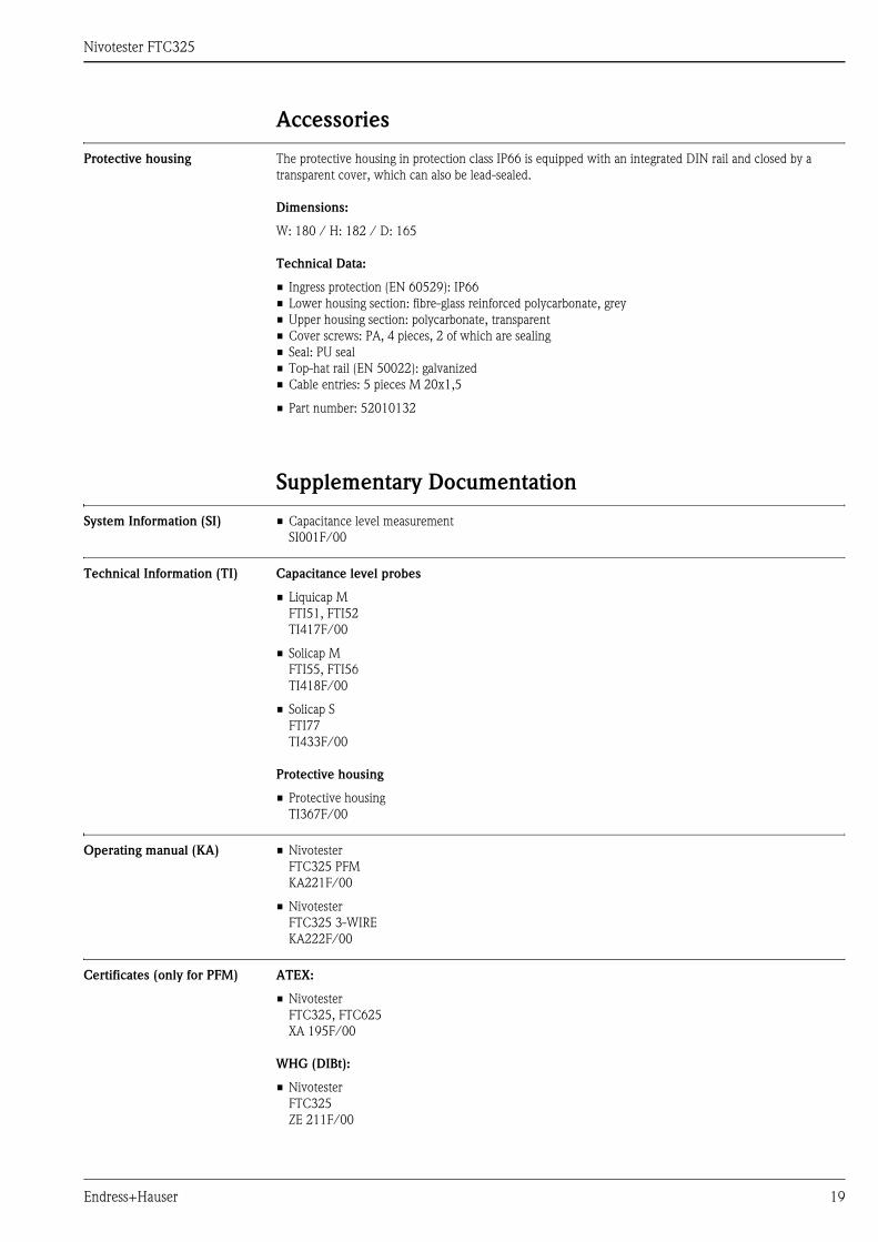
Accessories
Protective housing The protective housing in protection class IP66 is equipped with an integrated DIN rail and closed by a
transparent cover, which can also be lead-sealed.
Dimensions:
W: 180 / H: 182 / D: 165
Technical Data:
• Ingress protection (EN 60529): IP66
• Lower housing section: fibre-glass reinforced polycarbonate, grey
• Upper housing section: polycarbonate, transparent
• Cover screws: PA, 4 pieces, 2 of which are sealing
• Seal: PU seal
• Top-hat rail (EN 50022): galvanized
• Cable entries: 5 pieces M 20x1,5
• Part number: 52010132
Supplementary Documentation
System Information (SI) • Capacitance level measurement
SI001F/00
Technical Information (TI) Capacitance level probes
• Liquicap M
FTI51, FTI52
TI417F/00
• Solicap M
FTI55, FTI56
TI418F/00
• Solicap S
FTI77
TI433F/00
Protective housing
• Protective housing
TI367F/00
Operating manual (KA) • Nivotester
FTC325 PFM
KA221F/00
• Nivotester
FTC325 3-WIRE
KA222F/00
Certificates (only for PFM) ATEX:
• Nivotester
FTC325, FTC625
XA 195F/00
WHG (DIBt):
• Nivotester
FTC325
ZE 211F/00

Instruments International
Endress+HauserInstruments International AGKaegenstrasse 24153 ReinachSwitzerland
Tel. +41 61 715 81 00Fax +41 61 715 25 [email protected]
TI380F/00/EN/05.10
71115361
CCS/FM+SGML 6.0 ProMoDo71115361


![Nivotester FTL325P-#3#3 - portal.endress.com · CH1 CH2 C H3 325 [Ex ia] CH2 C H3 C H1 KA00168F/00/A6/13.15 71296989 Products Solutions Service Operating Instructions Nivotester FTL325P-#3#3](https://static.fdocuments.us/doc/165x107/5aef6c6c7f8b9a572b8e12b9/nivotester-ftl325p-33-ch2-c-h3-325-ex-ia-ch2-c-h3-c-h1-ka00168f00a61315.jpg)