New Developments in Tooth Contact Analysis (TCA) and Loaded TCA for ... - Gear Technology › issues...
10
26 GEAR TECHNOLOGY May 2007 www.geartechnology.com Introduction Tooth Contact Analysis (TCA) and Loaded Tooth Contact Analysis (LTCA) are two powerful tools for the design and analysis of spiral bevel and hypoid gear drives. Typical outputs of TCA and LTCA are the graphs of contact Dr. Qi Fan and Dr. Lowell Wilcox New Developments in Tooth Contact Analysis (TCA) and Loaded TCA for Spiral Bevel and Hypoid Gear Drives Management Summary In the early 1960s, the Tooth Contact Analysis (TCA) technique was introduced for the theoretical analysis of the con- tact characteristics and running quality of spiral bevel and hypoid gear drives (Ref. 1). Application of the TCA program has substantially reduced the lengthy trial-and-error procedure for the design and development of spiral bevel and hypoid gear drives. In the late 1970s, the tooth contact analysis under loaded conditions, the Loaded TCA (LTCA), was developed (Ref. 2). The Loaded Tooth Contact Analysis (LTCA) program provides a more realistic picture of tooth contact characteris- tics because tooth deformation and shaft deflection due to loading are taken into account for determination of the actual geometry of contacting tooth surfaces. Both techniques have been accepted and applied throughout the bevel gear industry and have become powerful tools for the design and manufacturing of high quality spiral bevel and hypoid gears. In the TCA computation, the gear and pinion tooth surface geometries are mathematically represented by the machine settings and cutter specifications. The existing TCA algorithms and programs were developed specifically corresponding to each method of tooth surface generation process and type of bevel gear drives. The application of modern CNC bevel gear generators has provided more motion freedoms for bevel gear generations. Traditional generating methods such as modified roll and helical motion can be considered as special cases of the possible motions of the CNC 6-axis generators. An advanced tooth surface modification approach has been developed by using the Universal Motion Concept (UMC) (Ref. 3). The UMC technique can be applied for a sophisticated modification of spiral bevel and hypoid gear tooth sur- faces. In order to satisfy the need for accurate modeling and analysis of the advanced design and modification of spiral bevel and hypoid gears, a new generalized tooth surface generation algorithm and a TCA approach are developed. This paper comprehensively describes these developments as applied to spiral bevel and hypoid gears produced by both the face- milling and face-hobbing processes. LTCA was first developed assuming that the contact tooth surfaces are subject to Hertzian deformation, and approxi- mating tooth stiffness by a cantilever beam model with modifications to improve deflection calculations at the ends of the teeth. With the advances in computational and memory capacities of modern computers, the finite element analysis (FEA) has been applied to gear tooth strength evaluations. A special FEA software package called T900 was developed for the strength analysis of spiral bevel and hypoid gears (Ref. 4). T900 provides an integrated environment with automatic pre- processor, post-processor, and graphic visualization of the FEA results, including the behavior of the contact under load, contact stress and bending stress. Based on the improved FEA models and algorithms, a new LTCA program was developed as a subset of T900. LTCA provides the gear designers with detailed information on how the tooth contact pattern and transmission errors behave as a function of torque input, initial contact position and mounting deflections. The LTCA model uses TCA-generated tooth surface and fillet coordinates to define the gear and pinion geometry and to identify the instant contact positions. The non- linear growth and movement of the area of contact common to the gear and pinion teeth are predicted by the use of spe- cialized gap elements, the applied torque and axle stiffness input data. Multi-tooth finite element models are developed and applied for both the pinion and the gear. This article is printed with permission of the copyright holder The American Gear Manufacturers Association. State- ments presented in this paper are those of the author and may not represent the position or opinion of the American Gear Manufacturers Association. patterns and transmission errors. TCA and LTCA respective- ly simulate gear meshing contact characteristics under light load and under significant load. TCA and LTCA programs have been widely employed by gear engineers and research- ers in their design of high strength and low noise spiral bevel
Transcript of New Developments in Tooth Contact Analysis (TCA) and Loaded TCA for ... - Gear Technology › issues...

26 GEARTECHNOLOGY May 2007 www.geartechnology.com
IntroductionTooth Contact Analysis (TCA) and Loaded Tooth
Contact Analysis (LTCA) are two powerful tools for the design and analysis of spiral bevel and hypoid gear drives. Typical outputs of TCA and LTCA are the graphs of contact
Dr. Qi Fan and Dr. Lowell Wilcox
New Developments in Tooth Contact Analysis (TCA) and Loaded TCA for Spiral Bevel
and Hypoid Gear Drives
Management SummaryIn the early 1960s, the Tooth Contact Analysis (TCA) technique was introduced for the theoretical analysis of the con-
tact characteristics and running quality of spiral bevel and hypoid gear drives (Ref. 1). Application of the TCA program has substantially reduced the lengthy trial-and-error procedure for the design and development of spiral bevel and hypoid gear drives.
In the late 1970s, the tooth contact analysis under loaded conditions, the Loaded TCA (LTCA), was developed (Ref. 2). The Loaded Tooth Contact Analysis (LTCA) program provides a more realistic picture of tooth contact characteris-Loaded Tooth Contact Analysis (LTCA) program provides a more realistic picture of tooth contact characteris-Loaded Tooth Contact Analysistics because tooth deformation and shaft deflection due to loading are taken into account for determination of the actual geometry of contacting tooth surfaces.
Both techniques have been accepted and applied throughout the bevel gear industry and have become powerful tools for the design and manufacturing of high quality spiral bevel and hypoid gears.
In the TCA computation, the gear and pinion tooth surface geometries are mathematically represented by the machine settings and cutter specifications. The existing TCA algorithms and programs were developed specifically corresponding to each method of tooth surface generation process and type of bevel gear drives. The application of modern CNC bevel gear generators has provided more motion freedoms for bevel gear generations. Traditional generating methods such as modified roll and helical motion can be considered as special cases of the possible motions of the CNC 6-axis generators. An advanced tooth surface modification approach has been developed by using the Universal Motion Concept (UMC) (Ref. 3). The UMC technique can be applied for a sophisticated modification of spiral bevel and hypoid gear tooth sur-faces.
In order to satisfy the need for accurate modeling and analysis of the advanced design and modification of spiral bevel and hypoid gears, a new generalized tooth surface generation algorithm and a TCA approach are developed. This paper comprehensively describes these developments as applied to spiral bevel and hypoid gears produced by both the face-milling and face-hobbing processes.
LTCA was first developed assuming that the contact tooth surfaces are subject to Hertzian deformation, and approxi-mating tooth stiffness by a cantilever beam model with modifications to improve deflection calculations at the ends of the teeth. With the advances in computational and memory capacities of modern computers, the finite element analysis (FEA) has been applied to gear tooth strength evaluations. A special FEA software package called T900 was developed for the T900 was developed for the T900strength analysis of spiral bevel and hypoid gears (Ref. 4). T900 provides an integrated environment with automatic pre-T900 provides an integrated environment with automatic pre-T900processor, post-processor, and graphic visualization of the FEA results, including the behavior of the contact under load, contact stress and bending stress.
Based on the improved FEA models and algorithms, a new LTCA program was developed as a subset of T900. LTCA provides the gear designers with detailed information on how the tooth contact pattern and transmission errors behave as a function of torque input, initial contact position and mounting deflections. The LTCA model uses TCA-generated tooth surface and fillet coordinates to define the gear and pinion geometry and to identify the instant contact positions. The non-linear growth and movement of the area of contact common to the gear and pinion teeth are predicted by the use of spe-cialized gap elements, the applied torque and axle stiffness input data. Multi-tooth finite element models are developed and applied for both the pinion and the gear.
This article is printed with permission of the copyright holder The American Gear Manufacturers Association. State-ments presented in this paper are those of the author and may not represent the position or opinion of the American Gear Manufacturers Association.
patterns and transmission errors. TCA and LTCA respective-ly simulate gear meshing contact characteristics under light load and under significant load. TCA and LTCA programs have been widely employed by gear engineers and research-ers in their design of high strength and low noise spiral bevel
Cutter head
Face Hobbing
Generating gear
Extended epicycloid
Face Milling
Generating gear
Circular arc
Cutter head
www.geartechnology.com May 2007 GEARTECHNOLOGY 27
1a
1b
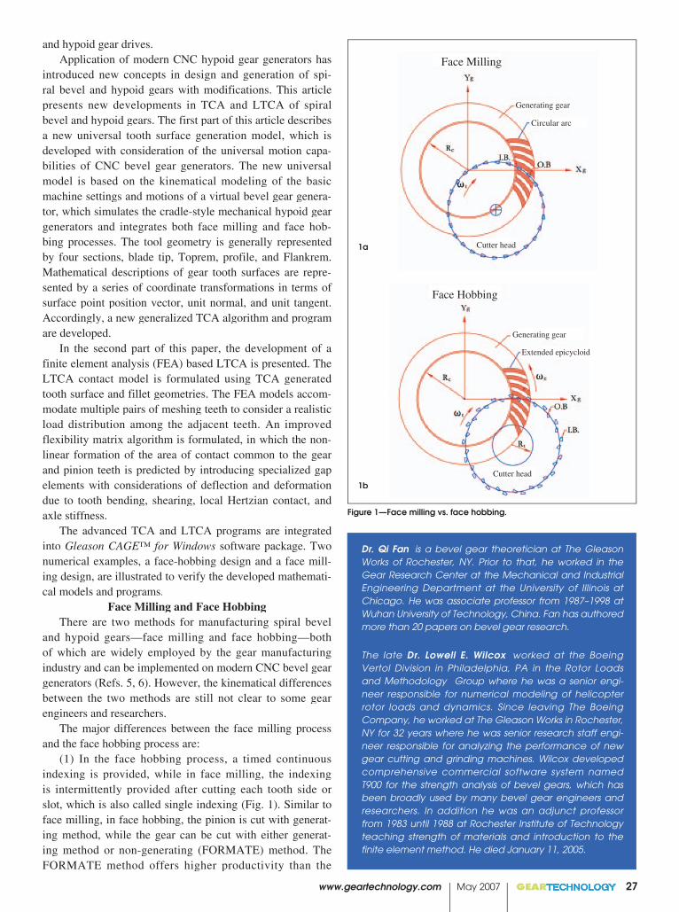
Figure 1—Face milling vs. face hobbing.
and hypoid gear drives.Application of modern CNC hypoid gear generators has
introduced new concepts in design and generation of spi-ral bevel and hypoid gears with modifications. This article presents new developments in TCA and LTCA of spiral bevel and hypoid gears. The first part of this article describes a new universal tooth surface generation model, which is developed with consideration of the universal motion capa-bilities of CNC bevel gear generators. The new universal model is based on the kinematical modeling of the basic machine settings and motions of a virtual bevel gear genera-tor, which simulates the cradle-style mechanical hypoid gear generators and integrates both face milling and face hob-bing processes. The tool geometry is generally represented by four sections, blade tip, Toprem, profile, and Flankrem. Mathematical descriptions of gear tooth surfaces are repre-sented by a series of coordinate transformations in terms of surface point position vector, unit normal, and unit tangent. Accordingly, a new generalized TCA algorithm and program are developed.
In the second part of this paper, the development of a finite element analysis (FEA) based LTCA is presented. The LTCA contact model is formulated using TCA generated tooth surface and fillet geometries. The FEA models accom-modate multiple pairs of meshing teeth to consider a realistic load distribution among the adjacent teeth. An improved flexibility matrix algorithm is formulated, in which the non-linear formation of the area of contact common to the gear and pinion teeth is predicted by introducing specialized gap elements with considerations of deflection and deformation due to tooth bending, shearing, local Hertzian contact, and axle stiffness.
The advanced TCA and LTCA programs are integrated into Gleason CAGE™ for Windows software package. Two numerical examples, a face-hobbing design and a face mill-ing design, are illustrated to verify the developed mathemati-cal models and programs.
Face Milling and Face HobbingThere are two methods for manufacturing spiral bevel
and hypoid gears—face milling and face hobbing—both of which are widely employed by the gear manufacturing industry and can be implemented on modern CNC bevel gear generators (Refs. 5, 6). However, the kinematical differences between the two methods are still not clear to some gear engineers and researchers.
The major differences between the face milling process and the face hobbing process are:
(1) In the face hobbing process, a timed continuous indexing is provided, while in face milling, the indexing is intermittently provided after cutting each tooth side or slot, which is also called single indexing (Fig. 1). Similar to face milling, in face hobbing, the pinion is cut with generat-ing method, while the gear can be cut with either generat-ing method or non-generating (FORMATE) method. The FORMATE method offers higher productivity than the
Dr. Qi Fan is a bevel gear theoretician at The Gleason Works of Rochester, NY. Prior to that, he worked in the Gear Research Center at the Mechanical and Industrial Engineering Department at the University of Illinois at Chicago. He was associate professor from 1987–1998 at Wuhan University of Technology, China. Fan has authored more than 20 papers on bevel gear research.
The late Dr. Lowell E. Wilcox worked at the Boeing Vertol Division in Philadelphia, PA in the Rotor Loads and Methodology Group where he was a senior engi-neer responsible for numerical modeling of helicopter rotor loads and dynamics. Since leaving The Boeing Company, he worked at The Gleason Works in Rochester, NY for 32 years where he was senior research staff engi-neer responsible for analyzing the performance of new gear cutting and grinding machines. Wilcox developed comprehensive commercial software system named T900 for the strength analysis of bevel gears, which has been broadly used by many bevel gear engineers and researchers. In addition he was an adjunct professor from 1983 until 1988 at Rochester Institute of Technology teaching strength of materials and introduction to the finite element method. He died January 11, 2005.

generating method because the generating roll is not applied. However, the generating method offers more freedom in controlling the tooth surface geometries.
(2) The lengthwise tooth curve of face-milled bevel gears is a circular arc with a curvature radius equal to the radius of the cutter, while the lengthwise tooth curve of face-hobbed gears is an extended epicycloid that is kinematically gener-ated during the relative indexing motion.
(3) Face hobbing gear designs use uniform tooth depth systems while face milling gear designs may use either uni-form depth or various tapered tooth depth systems.
Theoretically, the bevel gear cutting process is based on the generalized concept of bevel gear generation in which the mating gear and the pinion can be considered respective-ly generated by the complementary virtual generating gears. Figure 2 shows a configuration of a bevel pinion generation, which consists of a virtual generating gear, a cutter head with blades, and the workpiece (the pinion). The rotational motion of the virtual generating gear is implemented by the cradle mechanism of a bevel gear generator. Generally, the tooth surfaces of the generating gears are kinematically formed by the traces of the cutting edges of the blades. In practice, in order to introduce mismatch of the generated tooth surfaces, modification is applied on the generating gear tooth surface and on the generating motion.
In the spiral bevel and hypoid gear generation process, two sets of related motions are generally defined. The first set of related motion is the rotation of the tool (cutter head) and rotation of the workpiece, namely,
(1)
Here, tω and wω denote the angular velocities of the tool and the workpiece; tN and wN denote the number of the blade groups and the number of teeth of the workpiece, respectively. This related motion provides the continuous indexing between the tool and the work for the face hobbing process. The indexing relationship also exists between the rotation of the tool and the generating gear as,
(2)
where cω and cN denote the angular velocity and the number of teeth of the generating gear, respectively. In the face hobbing process, the indexing motion between the tool and the generating gear kinematically forms the tooth surface of the generating gear with an extended-epicycloid lengthwise tooth curve.
However, Equations 1 and 2 are not applicable for the face milling process where the cutter rotates independently at its selected cutting speed and forms a surface of revolution for the generating gear teeth with a circular lengthwise curve as shown in Fig. 1a.
The second set of related motions is the rotation of the generating gear and rotation of the workpiece. Such a related
28 GEARTECHNOLOGY May 2007 www.geartechnology.com
Figure 3— Phoenix® II 275HC hypoid gear generator.
Figure 4—Kinematical model of a hypoid gear generator.
t
c
c
t
N
N=
ωω
t
w
w
t
N
N=
ωω
Figure 2—Generalized bevel gear generation configuration.
Generating gearVirtualVirtualVirtual
CutterheadCutterhead
Work
Blades

motion is called rolling or generating motion and is repre-sented as
(3)
where aR is called the ratio of roll. The generating motion is provided for both face milling and face hobbing processes when the gear or pinion is cut in the generating method. In the non-generating (FORMATE) process, which is usually applied to the gear, both the generating gear and the workpiece are held at rest, and only the cutter rotation is provided. Therefore, the gear tooth surfaces are actually the complementary copy of the generating tooth surfaces, which are formed by the cutter motion described above.
Generalized Spiral Bevel and Hypoid Gear Tooth Surface Generation Model
Both face milling and face hobbing processes can be
www.geartechnology.com May 2007 GEARTECHNOLOGY 29
Machine plane
Machine center
Machine frame
Sliding base
Sliding base 11
5a 5b
5e
Machine plane
Machine center
5d
Referencepoint
5g Cutter center
Cradle Cradle
5h
Cutter-head
Tilt wedge base
Cutter-head
BladesCutter-head carrier
5f
Figure 5—Machine motion elements with applied coordinate systems.
5c
implemented on the CNC hypoid gear generating machines. Figure 3 shows a Phoenix® II 275HC Hypoid Gear Generator. A new kinematical model of tooth surface gen-eration is developed, based on the traditional cradle-style mechanical machine. The purpose of developing this model is to virtually represent each machine tool setting element as an individual motion unit and to implement a given func-tion of motion. These virtual motions can be realized by the CNC hypoid gear generator through the computer translation codes on the machine. The six axes of the CNC hypoid gear generator move together in a numerically controlled relation-ship with changes in displacements, velocities, and accelera-tions to implement the prescribed motions and produce the target tooth surface geometry.
The generalized tooth surface generation model consists of the eleven motion elements shown in Figure 4. The cradle
aw
c
c
w RN
N==
ωω

represents the generating gear, which provides generating roll motion between the generating gear and the generated workpiece. In the non-generating process, the cradle is held stationary. Basically, these motion elements represent the machine tool settings in a dynamic manner in terms of the cradle rotation parameter.
The generalized machine settings are: (1) ratio of roll aR ; (2) sliding base bX ; (3) radial setting s ; (4) offset mE ; (5) work head setting pX ; (6) root angle mγ ; (7) swivel j ; and (8) tool tilt i . The Universal Motion Concept (UMC) repre-sents these machine settings in higher-order polynomials and provides strong flexibility of generating comprehensively crowned tooth surfaces (Ref. 3). The UMC is the extension of traditional modified roll, helical motion, and vertical motion to all machine settings.
The motion elements of the kinematical model in Figure 4 are analytically isolated relative to each other (Fig. 5). A sequence of coordinate systems is associated with the model to transform the relative motions of the elements. Coordinate system mS , called machine coordinate system, is fixed to the machine frame and considered as the reference of the related motions. System mS defines the machine plane and the machine center. The sequence of the applied coordinate systems is wS , oS , pS , rS , sS , mS , cS , eS , jS , and
iS , which defines the position vector, unit tangent, and unit normal at a point on the work tooth surface in two-parameter forms as
(4)
(5)
(6)
“here subscript w” denotes that the vectors are repre-sented in the work coordinate system wS . This generalized formulation of the generating process accommodates both face milling and face hobbing processes with both generat-ing and long-generating cutting methods.
In addition, a generalized representation of the blade geometry is also developed (Fig. 6). The tool geometry is defined by the parameters of the blade sharpening and instal-lation in the cutter head, which are nominal blade pressure angle, blade offset angle, rake angle, and effective hook angle. The blades are generally considered consisting of four segments—(a), (b), (c), (d)—corresponding to the blade tip, Toprem, profile, and Flankrem.
An example of the pinion and gear tooth surfaces of a hyp-oid gear drive is generated by using the developed mathematical models and is illustrated in Figure 7. The tooth surface genera-tion algorithm is fundamental to the tooth contact analysis and automatic generation of finite element discrete models.
Advanced Tooth Contact Analysis (TCA)Tooth Contact Analysis (TCA) is a computational
approach for analyzing the nature and quality of the meshing contact in a pair of gears. The concept of TCA was originally
O.B. (Outside Blade)
projection ofcutter axis
blade tip
30 GEARTECHNOLOGY May 2007 www.geartechnology.com
6a
6b
I.B. (Inside Blade)
projection ofcutter axis
blade tip
Figure 6—Basic geometry of blades. (a) Pinion tooth surfaces. (b) Gear tooth surfaces.
Figure 7—Pinion and gear tooth surfaces of a hypoid gear drive.
7a
7b
),( θuww rr =
),( θuww tt =
),( θuww nn =
Pinion Tooth Surfaces.
Gear Tooth Surfaces.

www.geartechnology.com www.geartechnology.com www.geartechnology.com May 2007 GEARTECHNOLOGY 31
Common tangent plane
Figure 8—Tooth surface contact.
Gear axial(G)(G)
Shaft angle(�)(�)
Pinion axial(P)(H)
Gear Head(E)(V)
Figure 9—Definition of mounting deflections and adjustments.
=⋅
=⋅×
=−
0
0)(
0
]1[]2[
]1[]2[]2[
]2[]1[
ff
fff
ff
nt
ntn
rr
=⋅
=⋅×
=−
0
0)(
0
]2[]1[
]2[]1[]1[
]2[]1[
ff
fff
ff
nt
ntn
rr
introduced in early 1960s as a research tool, and applied to spiral bevel and hypoid gears (Refs. 1, 7). Application of TCA technology has resulted in significant improvement in the development of bevel gear pairs, under given contact conditions.
Based on the new tooth surface generation model dis-cussed above, an advanced TCA program is developed. The new TCA algorithm is based on the following mathematical formulations, namely,
(7)
(8)
Geometrically, vector ][][ if
if tn × and ][i
ft (i=1, 2) are two orthogonal vectors that lie in the tangent planes of the pin-ion tooth surface 1Σ (i=1) and gear tooth surface 2Σ (i=2). When the two surfaces contact at point P, the tangent planes coincide and become a common tangent plane (Fig. 8). Considering the equations of meshing, Equations 7 or 8 gen-erally yield five independent equations, and can be solved if the related Jacobian differs from zero (Ref. 8). Consequently, a series of contact points and the corresponding transmission errors can be obtained, which formulate the TCA output as the bearing contact patterns and the graph of transmission errors. The transmission error (TE) is defined as
(9)
Where φ10 and φ20 are the initial angular displacement of the pinion and the gear when the tooth surfaces are in con-tact at the initial conjugate contact position where the TE = TE = TE0; 1N and 2N are the tooth numbers of the pinion and the gear, respectively.
Simulation of changes of the assembly errors and mis-alignments caused by the deflection of the gear shafts are taken into account. For this purpose, the adjusting param-eters, gear head offset change E∆E∆E , gear axial change, ∆Gpinion axial change P∆P∆P , and shaft angle change are ∆∑
incorporated into the TCA model (Fig. 9). The output of a TCA program is the scaled graphs of transmission errors and tooth-bearing contact patterns that predict the results from a bevel gear testing machine. The program incorporates tooth Toprem, Flankrem, and edge contact on the whole tooth sur-Toprem, Flankrem, and edge contact on the whole tooth sur-face, including those surface parts that are generated by the blade Toprem and Flankrem.
Conventionally, there are two cases of bearing contact patterns that are identified as “single meshing pattern” and “multiple meshing pattern.” In the multiple meshing pat-
� ���� ���� �� �����
����
terns, the adjacent pairs of meshing teeth are considered simultaneously. And, the path of contact reflects one pitch meshing because the following pairs of teeth take over the meshing process. In single meshing pattern, only one pair of teeth meshing is investigated and the adjacent meshing is ignored. In this case, the contact pattern covers the larger area of the tooth surface. Meanwhile, tooth tip edge contact or Toprem contact might be observed in the single mesh-ing case because no neighboring teeth interrupt the meshing process.
In practice, when the surface separation of the mating gears is small, or the two mating surfaces are close to conju-gate, a large contact pattern might be observed from the test-ing machine, which may correspond to the single meshing

contact pattern of TCA. When the tooth surface separation is considerable, or the magnitude of tooth surface crowning is significant, the multiple meshing contact patterns might be obtained from the testing machine.
The developed program is able to simulate both the single meshing and the multiple meshing of a gear set pair. TCA results for the mean, toe, and heel positions are pro-vided, which is the Gleason convention of TCA outputs. The adjusting parameters E∆E∆E and P∆P∆P are computed in order to achieve the given bearing contact pattern positions.
The TCA program is able to simulate the ‘zero’ assem-bling conditions under which all the adjusting parameters are equal to zero. The developed TCA program accommodates all kinds of modified and corrected tooth surfaces, generated by both face milling and face hobbing processes. The tip edge contact and the Toprem contact can be simulated.
Edge contact results in unexpected early failure of a gear drive because of highly concentrated contact stress gener-ated between the tip of one member and the root flank of the other. Edge contact should be avoided by increasing the magnitude of the tooth surface crowning. The program offers the ability for the users to simulate meshing contact under user-defined misalignments, or user-defined, initial conju-gate contact positions.
Development of FEA-Based Loaded Tooth Contact Analysis (LTCA)
Loaded TCA provides a realistic picture of tooth contact behavior under given loads (applied torques) and axle deflec-tions. The advanced development of LTCA is based upon following ideas and considerations:
(1) Tooth surface geometry is exactly defined and the TCA is executed. The TCA results provide bench contact pattern and the motion graph from which instant contact positions, and the number of adjacent meshing tooth pairs, can be identified. For example, Figure 10 shows the posi-tions of contact lines respectively on three pairs of contact teeth at a given pinion rotation angle pΦ .
(2) Loaded contact is assumed along the conjugate line of tooth contact, which is close to the major axis of the contact ellipse (Fig.11). Therefore, the conjugate contact lines on the gear and pinion tooth surfaces are generated and represented by discrete points, which are the potential candidate contact points under load.
(3) The governing equations are derived by using the general concept of flexibility matrix approach, namely,
(10)
(11)
where C is the combined compliance matrix which reflects the compliances of the gear, pinion and housing; fis the vector of normal load distribution along the line of contact; d is the displacement vector representing the gaps d is the displacement vector representing the gaps dbetween the corresponding contact nodes of the gear and the
32 GEARTECHNOLOGY May 2007 www.geartechnology.com
CandidateContact Point
ConjugateLine of Contact
Figure 11—Conjugate lines and contact points on the gear tooth surface.
Figure 12— FEA model of the gear.
Pinion Rotation
Pair 1 Pair 3
Pair 2
Figure 10—Identification of instant contact positions of multiple pairs of contact teeth.
Trf =×
���

www.geartechnology.com May 2007 GEARTECHNOLOGY 33
Figure 13— FEA model of the pinion.
Point LoadSolution
CandidateContact Point
ConjugateLine of Contact
Figure 14—Interpolation scheme.
Table 1—Data of Design A and B.Design A: Face Hobbing (Hypoid) (FORMATE Gear)
Design B: Face Milling (Hypoid) (Generated Gear)
Pinion (Left Hand)
Gear (Right Hand)
Pinion (Right Hand)
Gear (Left Hand)
Number of teeth
11 39 17 27
Diametral Pitch 5.015 4.480
Face Width 1.611" 1.325" 1.575" 1.575"
Pinion Offset 1.5" 0.394"
Shaft Angle 90° 90°
Outer Cone Distance
3.821" 4.390" 3.648"3.744"
Mean Cone Distance
2.965" 3.681" 2.851" 2.964"
Outside Diameter
3.737" 7.825" 4.674" 6.214"
Cutter Radius 3.465" 2.500"
pinion under a given torque; r is the position vector of con-r is the position vector of con-rtacting points; and T is the applied torque vector.T is the applied torque vector.T
(4) The compliance matrix C consists of two major parts, (i) simulated stiffness of axle housing by parameters ∆E, ∆P, ∆G, and ∆a in proportion to the applied torque and (ii) the gear and pinion compliances determined by FEA pro-cess, in which a special gap element is formulated by adding the Weber’s components of deflection (Ref. 4). Application of the special gap elements allows including the deflection and deformation due to not only bending and shearing, but also the local Hertzian contact. Parameters E∆E∆E , P∆P∆P , G∆ , and α∆are defined as the relative axle deflections of the pinion, with respect to the gear. They are normally derived from experi-mental measurements of axle deflections under controlled conditions, and they can also be estimated through FEA cal-culation.
(5) The FEA meshing models with multiple teeth are automatically generated, using the exact tooth surface gener-ating model for the spiral bevel and hypoid gears generated on both mechanical and CNC machines. The multiple-tooth models allow simulating load sharing among several adja-cent pairs of teeth. Figures 12 and 13 show the gear and pin-ion FEA models with the emphasized nodes representing the boundary constraints.
(6) The total number of elements in the models can be chosen by the designer through the input interface by select-ing the element numbers in tooth thickness, profile, and lengthwise directions. This feature provides flexibility for the program running on computers with different CPU levels to balance the running time and accuracy. The input torque can be applied through either pinion or gear.
(7) The displacement field of the FEA meshing nodes on the tooth surface is determined by applying a unit load on each surface node. By using this displacement field, a higher-order polynomial interpolation scheme is used to determine the primary and secondary deflections of loaded contact points, which are normally not coincident with the FEA meshing nodes on the tooth surface (Fig. 14).
(8) Solving the governing equations needs an iteration process in which the kinematical approach k can be assumed, and eventually determined together with the load distribution and gap vectors. As an LTCA result, the loaded transmission error and contact pattern identified by the gaps at each con-tact position can be determined. The kinematical approach k represents the loaded transmission errors.
(9) Two values of torque need to be specified in LTCA. The first value of torque is the full-load torque applied to the gear or pinion, corresponding to the torque used in evaluat-ing the strength performance of the gear design. The second value of torque corresponds to the torque used in the deflec-tion tests that were conducted to determine ∆E, ∆P, ∆G, and ∆α . In general, the two values of torque may not be the same. The torque can be gradually applied as the percentage of the full torque. As torque is applied to a gear set, the area of contact between the gear and pinion teeth changes as the
34 GEARTECHNOLOGY May 2007 www.geartechnology.com
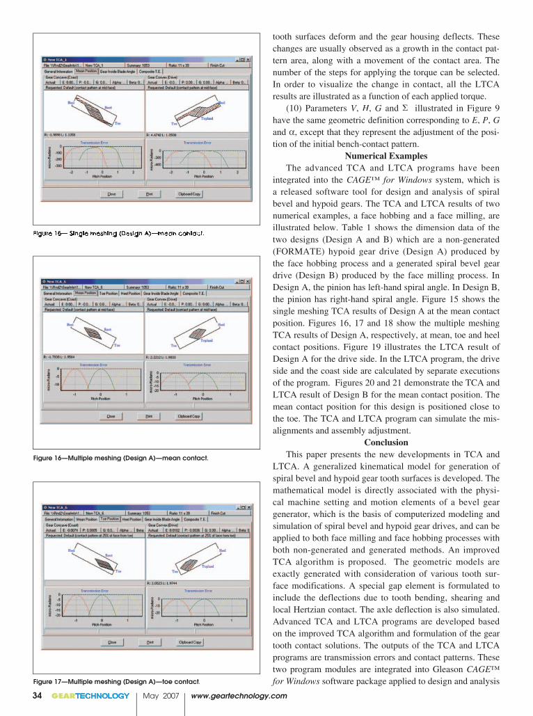
Figure 15— Single meshing (Design A)—mean contact.
Figure 16—Multiple meshing (Design A)—mean contact.
Figure 17—Multiple meshing (Design A)—toe contact.
tooth surfaces deform and the gear housing deflects. These changes are usually observed as a growth in the contact pat-tern area, along with a movement of the contact area. The number of the steps for applying the torque can be selected. In order to visualize the change in contact, all the LTCA results are illustrated as a function of each applied torque.
(10) Parameters V, V, V H, G and Σ illustrated in Figure 9 have the same geometric definition corresponding to E, P, Gand α, except that they represent the adjustment of the posi-tion of the initial bench-contact pattern.
Numerical ExamplesThe advanced TCA and LTCA programs have been
integrated into the CAGE™ for Windows system, which is a released software tool for design and analysis of spiral bevel and hypoid gears. The TCA and LTCA results of two numerical examples, a face hobbing and a face milling, are illustrated below. Table 1 shows the dimension data of the two designs (Design A and B) which are a non-generated (FORMATE) hypoid gear drive (Design A) produced by the face hobbing process and a generated spiral bevel gear drive (Design B) produced by the face milling process. In Design A, the pinion has left-hand spiral angle. In Design B, the pinion has right-hand spiral angle. Figure 15 shows the single meshing TCA results of Design A at the mean contact position. Figures 16, 17 and 18 show the multiple meshing TCA results of Design A, respectively, at mean, toe and heel contact positions. Figure 19 illustrates the LTCA result of Design A for the drive side. In the LTCA program, the drive side and the coast side are calculated by separate executions of the program. Figures 20 and 21 demonstrate the TCA and LTCA result of Design B for the mean contact position. The mean contact position for this design is positioned close to the toe. The TCA and LTCA program can simulate the mis-alignments and assembly adjustment.
ConclusionThis paper presents the new developments in TCA and
LTCA. A generalized kinematical model for generation of spiral bevel and hypoid gear tooth surfaces is developed. The mathematical model is directly associated with the physi-cal machine setting and motion elements of a bevel gear generator, which is the basis of computerized modeling and simulation of spiral bevel and hypoid gear drives, and can be applied to both face milling and face hobbing processes with both non-generated and generated methods. An improved TCA algorithm is proposed. The geometric models are exactly generated with consideration of various tooth sur-face modifications. A special gap element is formulated to include the deflections due to tooth bending, shearing and local Hertzian contact. The axle deflection is also simulated. Advanced TCA and LTCA programs are developed based on the improved TCA algorithm and formulation of the gear tooth contact solutions. The outputs of the TCA and LTCA programs are transmission errors and contact patterns. These two program modules are integrated into Gleason CAGE™ for Windows software package applied to design and analysis

of spiral bevel and hypoid gears. Two numerical examples are illustrated with TCA and LTCA results.
References:1. The Gleason Works Publication: Tooth Contact
Analysis Formulas and Calculation Procedures, SD 3115, April, 1964.
2. Krenzer, T. J., “Tooth Contact Analysis of Spiral Bevel and Hypoid Gears Under Load,” The Gleason Works, SD3458 (SAE 810688), 1981.
3. Stadtfeld, H. J., “Advanced Bevel Gear Technology,” The Gleason Works, Edition 2000.
4. Wilcox, L. E., T. D. Chimner, and G. C.Nowell, “Improved Finite Element Model for Calculating Stresses in Bevel and Hypoid Gear Teeth,” AGMA, 97FTM5, 1997.
5. Krenzer, T. J., “Face-Milling or Face Hobbing,” AGMA, Technical Paper, 90 FTM 13.
6. Pitts, L. S., and Boch, M. J., “Design and Development of Bevel and Hypoid Gears using the Face Hobbing Method,” Cat. #4332, The Gleason Works, 1997.
7. Krenzer, T. J., “Understanding Tooth Contact Analysis,” The Gleason Works Publication, SD3139B/3-81/GMD, 1981.
8. Litvin, F. L., “Gear Geometry and Applied Theory,“ Prentice Hall, 1994.
Figure 21—LTCA output of Design B—drive side.
Figure 20— TCA output of Design B—mean contact.
www.geartechnology.com May 2007 GEARTECHNOLOGY 35
Figure 19—LTCA output of Design A—drive side.
Figure 18— Multiple meshing (Design A)—heel contact.