Dr. Ashraf Armoush Supervisor Oday Jihad IbrahimTariq Ziad Yameen.

UOT/Elec. Eng. Dep. Module II Transformers Page 2 of 13 GE 207/Electrical Machines -I Part B 3-Phase Transformers 2nd Year/ Comm. Eng. Div. Lecture Note 7 Dr. Oday A. Ahmed
Three-Phase Transformer
A three-phase system in used to generate and transmit electric power. Three-phase voltages are raised or lowered by means of three-phase transformers. A three-phase transformer can be built in two ways:
► By suitably connecting a bank of three single-phase transformers (see figure a) or
► By constructing a three-phase transformer on a common magnetic structure (see figure b).
Fig. a
Fig. b
UOT/Elec. Eng. Dep. Module II Transformers Page 3 of 13 GE 207/Electrical Machines -I Part B 3-Phase Transformers 2nd Year/ Comm. Eng. Div. Lecture Note 7 Dr. Oday A. Ahmed

UOT/Elec. Eng. Dep. Module II Transformers Page 4 of 13 GE 207/Electrical Machines -I Part B 3-Phase Transformers 2nd Year/ Comm. Eng. Div. Lecture Note 7 Dr. Oday A. Ahmed

UOT/Elec. Eng. Dep. Module II Transformers Page 5 of 13 GE 207/Electrical Machines -I Part B 3-Phase Transformers 2nd Year/ Comm. Eng. Div. Lecture Note 7 Dr. Oday A. Ahmed

UOT/Elec. Eng. Dep. Module II Transformers Page 6 of 13 GE 207/Electrical Machines -I Part B 3-Phase Transformers 2nd Year/ Comm. Eng. Div. Lecture Note 7 Dr. Oday A. Ahmed

UOT/Elec. Eng. Dep. Module II Transformers Page 7 of 13 GE 207/Electrical Machines -I Part B 3-Phase Transformers 2nd Year/ Comm. Eng. Div. Lecture Note 7 Dr. Oday A. Ahmed

UOT/Elec. Eng. Dep. Module II Transformers Page 8 of 13 GE 207/Electrical Machines -I Part B 3-Phase Transformers 2nd Year/ Comm. Eng. Div. Lecture Note 7 Dr. Oday A. Ahmed

UOT/Elec. Eng. Dep. Module II Transformers Page 9 of 13 GE 207/Electrical Machines -I Part B 3-Phase Transformers 2nd Year/ Comm. Eng. Div. Lecture Note 7 Dr. Oday A. Ahmed

UOT/Elec. Eng. Dep. Module II Transformers Page 10 of 13 GE 207/Electrical Machines -I Part B 3-Phase Transformers 2nd Year/ Comm. Eng. Div. Lecture Note 7 Dr. Oday A. Ahmed

UOT/Elec. Eng. Dep. Module II Transformers Page 11 of 13 GE 207/Electrical Machines -I Part B 3-Phase Transformers 2nd Year/ Comm. Eng. Div. Lecture Note 7 Dr. Oday A. Ahmed

UOT/Elec. Eng. Dep. Module II Transformers Page 12 of 13 GE 207/Electrical Machines -I Part B 3-Phase Transformers 2nd Year/ Comm. Eng. Div. Lecture Note 7 Dr. Oday A. Ahmed
UOT/Elec. Eng. Dep. Module II Transformers Page 13 of 13 GE 207/Electrical Machines -I Part B 3-Phase Transformers 2nd Year/ Comm. Eng. Div. Lecture Note 7 Dr. Oday A. Ahmed

UOT/Elec. Eng. Dep. Module II Transformers Page 2 of 8 GE 207/Electrical Machines -I Part B 3-Phase and AutoTransformers 2nd Year/ Comm. Eng. Div. Lecture Note 8 Dr. Oday A. Ahmed
Auto Transformer Autotransformer is a special type of transformer having only one winding
such that part of the winding is common to the primary and secondary.
Obviously the two windings are electrically connected and it works on the
principle of conduction as well as induction. The power transfer in 2 winding
transformer is fully inductively while in autotransformer the power is
transferred from primary to secondary by both inductively as well as
conductively.
In autotransformer the output voltage can be stepped down (see Fig.b below) or stepped up (see Fig. c below) In step down autotransformer, the entire winding acts as a primary while
the part of the winding is used common to both primary and secondary.
Thus AB forms the primary having N1 turns while BC forms the secondary
with N2 turns. As N2 < N1, the output voltage V2 < V1 and it acts as a step
down autotransformer.
UOT/Elec. Eng. Dep. Module II Transformers Page 3 of 8 GE 207/Electrical Machines -I Part B 3-Phase and AutoTransformers 2nd Year/ Comm. Eng. Div. Lecture Note 8 Dr. Oday A. Ahmed
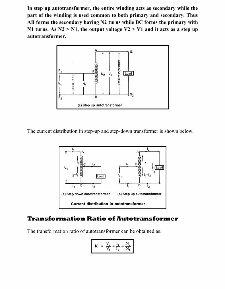
In step up autotransformer, the entire winding acts as secondary while the
part of the winding is used common to both primary and secondary. Thus
AB forms the secondary having N2 turns while BC forms the primary with
N1 turns. As N2 > N1, the output voltage V2 > V1 and it acts as a step up
autotransformer.
The current distribution in step-up and step-down transformer is shown below.
Transformation Ratio of Autotransformer The transformation ratio of autotransformer can be obtained as:

UOT/Elec. Eng. Dep. Module II Transformers Page 4 of 8 GE 207/Electrical Machines -I Part B 3-Phase and AutoTransformers 2nd Year/ Comm. Eng. Div. Lecture Note 8 Dr. Oday A. Ahmed
NOTE: K is greater than unity for step up autotransformer while K is less
than unity for step down autotransformer.
Power Transfer in Autotransformer
Using the figure below:
Input power = V1 I1 Output power = V2 I2
where: I1 =the current drawn from the supply, V1 = the input voltage. I2 =the load current, V2= the load voltage. Now BC portion has N2 turns and acts as secondary. The current induced in this secondary due to transformer action is I2- I1, while secondary induced voltage is V2. Pt = Power transformed inductively i.e. transformer action
UOT/Elec. Eng. Dep. Module II Transformers Page 5 of 8 GE 207/Electrical Machines -I Part B 3-Phase and AutoTransformers 2nd Year/ Comm. Eng. Div. Lecture Note 8 Dr. Oday A. Ahmed
Applications of Autotransformer
The various applications of an autotransformer are,
1. .For safely starting the machines like induction motors, synchronous
motors i.e. as a starter.
2. To give a small boost to a distribution cable to compensate for a voltage
drop i.e. as a booster.
3. As a furnace transformer to supply power to the furnaces at the required
supply voltage.
4. For interconnecting the systems which are operating roughly at same
voltage level.
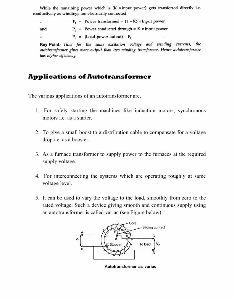
5. It can be used to vary the voltage to the load, smoothly from zero to the
rated voltage. Such a device giving smooth and continuous supply using
an autotransformer is called variac (see Figure below).

UOT/Elec. Eng. Dep. Module II Transformers Page 6 of 8 GE 207/Electrical Machines -I Part B 3-Phase and AutoTransformers 2nd Year/ Comm. Eng. Div. Lecture Note 8 Dr. Oday A. Ahmed
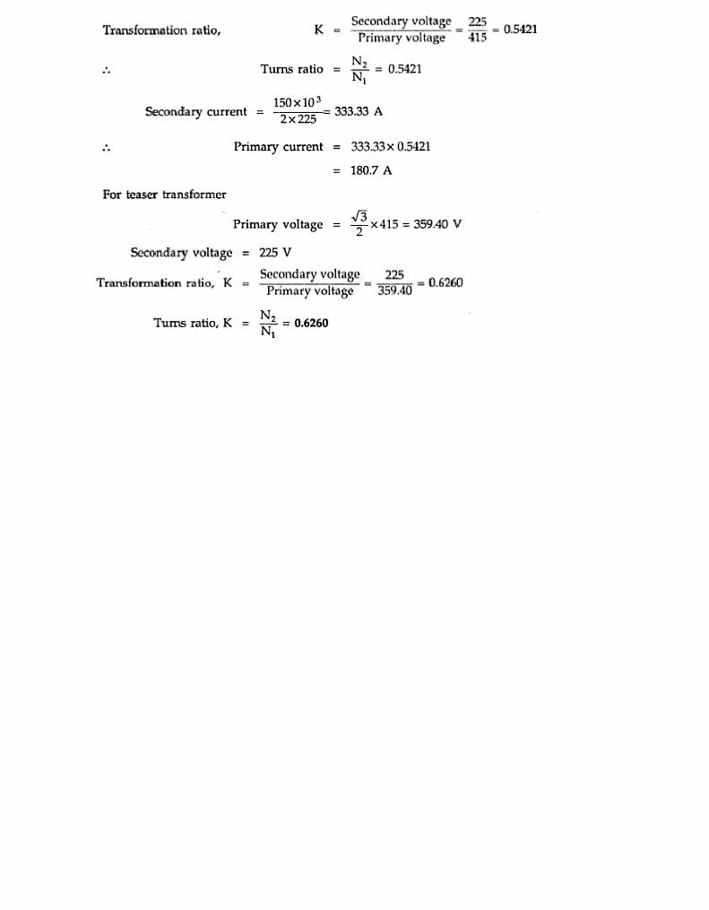
Solved Problems

UOT/Elec. Eng. Dep. Module II Transformers Page 7 of 8 GE 207/Electrical Machines -I Part B 3-Phase and AutoTransformers 2nd Year/ Comm. Eng. Div. Lecture Note 8 Dr. Oday A. Ahmed

UOT/Elec. Eng. Dep. Module II Transformers Page 8 of 8 GE 207/Electrical Machines -I Part B 3-Phase and AutoTransformers 2nd Year/ Comm. Eng. Div. Lecture Note 8 Dr. Oday A. Ahmed
Review Questions