Multi-Stage Setting Tool Technical Manual - corelab.com€¦ · Multi-Stage Setting Tool Technical...
22
Multi-Stage Setting Tool Technical Manual 1.687 MSST 2.125 MSST 2.687 MSST MAN-SET-010 (R05) Owen Oil Tools 12001 CR 1000 Godley, Texas, 76044, USA Phone: +1 (817) 551-0540 Fax: +1 (817) 551-1674 www.corelab.com/owen Warning: Use of Owen equipment contrary to manufacturer's specifications or operating instructions may result in property damage, serious injury or fatality. If you are not trained in the handling and use of explosive devices, do not attempt to use or assemble any Owen perforating systems or Owen firing devices. This technology is regulated by and, if exported, was exported from the United States in accordance with the Export Administration Regulations (EAR). Diversion contrary to U.S. law is prohibited. Export and/or re-export of this technology may require issuance of a license by the Bureau of Industry and Security (BIS), U.S. Department of Commerce. Consult the BIS, the EAR, and/or Owen Compliance Services, Inc. to determine licensing requirements for export or re-export of this technology. This document contains Confidential Information of Owen Oil Tools LP (Owen) and is furnished to the customer for information purposes only. This document must not be reproduced in any way whatsoever, in part or in whole, or distributed outside the customer organization, without first obtaining the express written authorization of Owen. This document is the property of Owen and returnable upon request of Owen. © 2009 Owen Oil Tools
Transcript of Multi-Stage Setting Tool Technical Manual - corelab.com€¦ · Multi-Stage Setting Tool Technical...

Multi-Stage Setting Tool
Technical Manual
1.687 MSST
2.125 MSST
2.687 MSST
MAN-SET-010 (R05)
Owen Oil Tools
12001 CR 1000
Godley, Texas, 76044, USA
Phone: +1 (817) 551-0540
Fax: +1 (817) 551-1674
www.corelab.com/owen
Warning: Use of Owen equipment contrary to manufacturer's specifications or operating instructions may result in property damage, serious injury orfatality. If you are not trained in the handling and use of explosive devices, do not attempt to use or assemble any Owen perforating systems or Owenfiring devices.
This technology is regulated by and, if exported, was exported from the United States in accordance with the Export Administration Regulations (EAR).Diversion contrary to U.S. law is prohibited. Export and/or re-export of this technology may require issuance of a license by the Bureau of Industry andSecurity (BIS), U.S. Department of Commerce. Consult the BIS, the EAR, and/or Owen Compliance Services, Inc. to determine licensing requirementsfor export or re-export of this technology.
This document contains Confidential Information of Owen Oil Tools LP (Owen) and is furnished to the customer for information purposes only. Thisdocument must not be reproduced in any way whatsoever, in part or in whole, or distributed outside the customer organization, without first obtaining theexpress written authorization of Owen. This document is the property of Owen and returnable upon request of Owen.
© 2009 Owen Oil Tools

1.687, 2.125, 2.687 MSST
Tech Manual
MAN-SET-010 (R05)page ii
1.687, 2.125, 2.687 MSST
Tech Manual
MAN-SET-010 (R05) page iii
Table of Contents
Description. . . . . . . . . . . . . . . . . . . . . . . . . . . . . . . . . . . . . . . . . . . . . 1Benefits/Capabilities . . . . . . . . . . . . . . . . . . . . . . . . . . . . . . . . . . . . . 1Operation . . . . . . . . . . . . . . . . . . . . . . . . . . . . . . . . . . . . . . . . . . . . . . 11.687 Inspection and Fishing Dimensions . . . . . . . . . . . . . . . . . . . . . 32.125 Inspection and Fishing Dimensions . . . . . . . . . . . . . . . . . . . . . 42.687 Inspection and Fishing Dimensions . . . . . . . . . . . . . . . . . . . . . 51.687 Schematics and Bill of Materials . . . . . . . . . . . . . . . . . . . . . . . 62.125 Schematics and Bill of Materials . . . . . . . . . . . . . . . . . . . . . . . 72.687 Schematics and Bill of Materials . . . . . . . . . . . . . . . . . . . . . . . 81.0 Pre-Assembly . . . . . . . . . . . . . . . . . . . . . . . . . . . . . . . . . . . . . . . 92.0 Assembly . . . . . . . . . . . . . . . . . . . . . . . . . . . . . . . . . . . . . . . . . . . 93.0 Pre-Disassembly . . . . . . . . . . . . . . . . . . . . . . . . . . . . . . . . . . . . 134.0 Manual Bleeding . . . . . . . . . . . . . . . . . . . . . . . . . . . . . . . . . . . . 145.0 Disassembly . . . . . . . . . . . . . . . . . . . . . . . . . . . . . . . . . . . . . . . 14

1.687, 2.125, 2.687 MSST
Tech Manual
MAN-SET-010 (R05)page iv

1.687, 2.125, 2.687 MSST
Tech Manual
MAN-SET-010 (R05) page 1
Description
Owen Multi-Stage Setting Tools have 2 working pistons that double the pulling strengthwhen compared to single stage tools. The burning of a power charge produces high-pressure gas for setting bridge plugs and tubing patches.
Benefits/Capabilities
• Pressure balanced top and bottom pistons.• Eliminates presetting of plugs and patches, caused by high hydrostatic pressure.• 15,000 psi pressure rating.
Operation
An electrically actuated, high temperature rated igniter located at the upper end of thetool is ignited and produces a flash flame which in turn, ignites the power charge that islocated directly below the igniter. The power charge is constructed of carefully controlledcombustible elements and begins a slow burn of approximately 30 seconds. Theresultant gas derived from the burning charge gradually builds up to high pressure andcauses the tool to stroke.
The pressurized gas travels down the center of both top pistons of the tool and out intoan annular cavity formed between the top pistons and tandem subs. The pressure actingon these areas drives the outside of the tool (consisting of top and bottom cylinders)downward, while the top and bottom pistons remain stationary. This motion anchors thebridge plug to the casing and then pulls the release stud of the plug in half, freeing thesetting tool for retrieval from the well.
An oil damper system is built into the tool to control the speed at which the tool strokes.As the tool elongates, this oil is forced through an annular orifice and out of the tool at acontrolled rate. This prevents the tool from stroking too fast and damaging the tool oncethe release stud pulls apart. Excess oil is purged out automatically during the assembly.Likewise, oil expansion caused by high temperature during running is purged in thesame manner.
Caution: It is mandatory that the tool is filled to capacity withoil after each use or damage to the tool will result!

1.687, 2.125, 2.687 MSST
Tech Manual
MAN-SET-010 (R05)page 2

1.687, 2.125, 2.687 MSST
Tech Manual
MAN-SET-010 (R05) page 3
1.687 Inspection and Fishing Dimensions
Note: Dimensions shown are critical. Whensetting tool components wear to a pointapproaching these figures, they must bereplaced. Do not use a component whosedimensions exceed the maximum weardimensions given below.
1.687, 2.125, 2.687 MSST
Tech Manual
MAN-SET-010 (R05)page 4
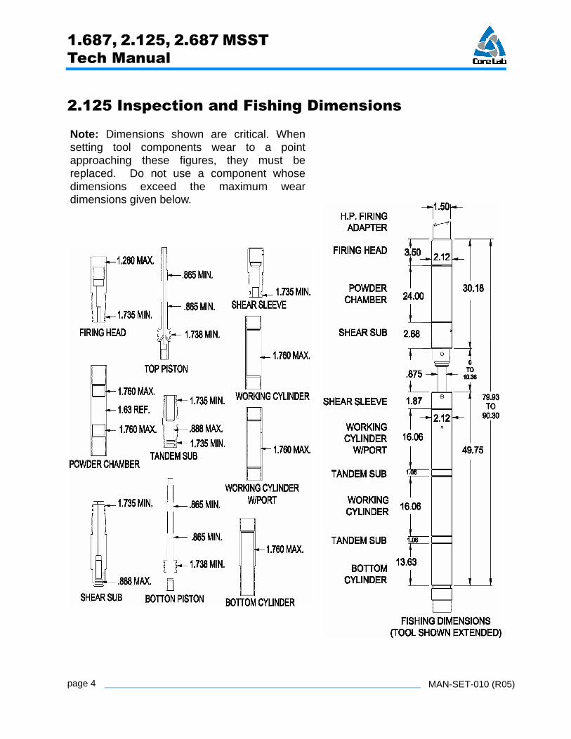
2.125 Inspection and Fishing Dimensions
Note: Dimensions shown are critical. Whensetting tool components wear to a pointapproaching these figures, they must bereplaced. Do not use a component whosedimensions exceed the maximum weardimensions given below.
1.687, 2.125, 2.687 MSST
Tech Manual
MAN-SET-010 (R05) page 5
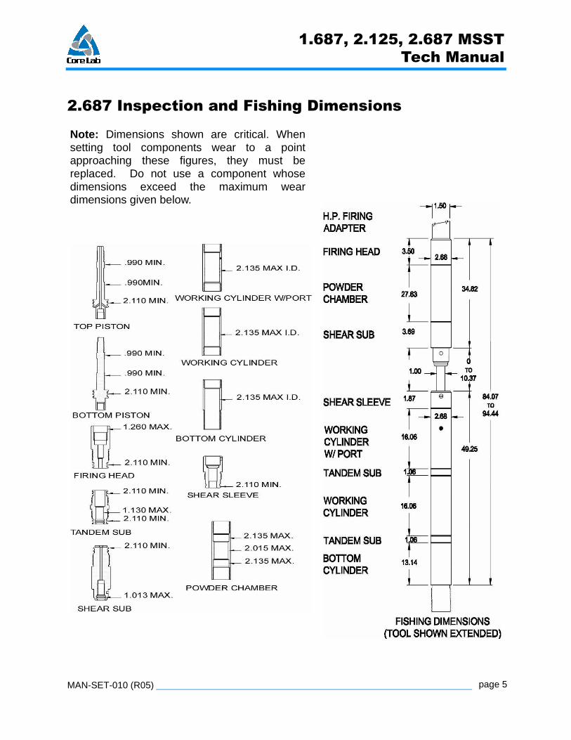
2.687 Inspection and Fishing Dimensions
Note: Dimensions shown are critical. Whensetting tool components wear to a pointapproaching these figures, they must bereplaced. Do not use a component whosedimensions exceed the maximum weardimensions given below.

1.687, 2.125, 2.687 MSST
Tech Manual
MAN-SET-010 (R05)page 6
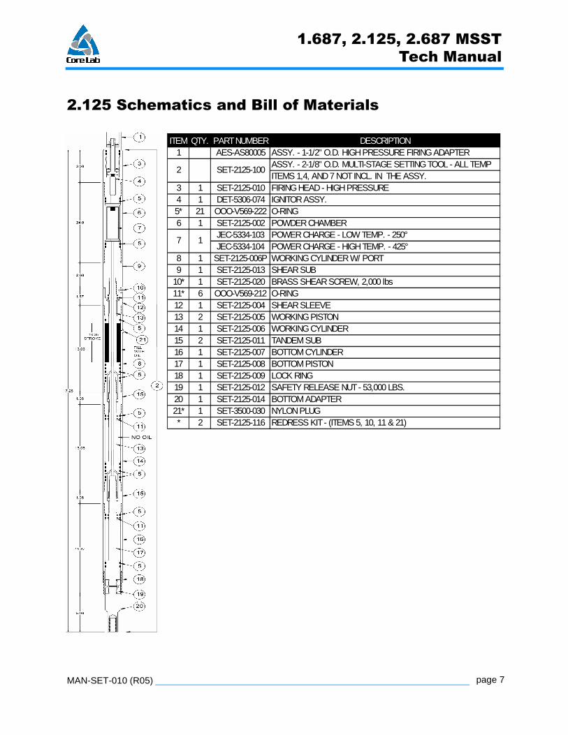
1.687 Schematics and Bill of Materials
ITEM QTY. PART NUMBER DESCRIPTION
1 AES-AS80005 ASSY. - 1-1/2" O.D. HIGH PRESSURE FIRING ADAPTERASSY. - 1-11/16" O.D. MULTI-STAGE SETTING TOOL - ALL TEMPITEMS 1,4 & 7 NOT INCL. IN EITHER ASSY.
3 1 SET-1687-010 FIRING HEAD - HIGH PRESSURE4 1 DET-5306-074 IGNITOR ASSY. 5* 21 OOO-V569-216 O-RING 6 1 SET-1687-102 POWDER CHAMBER7 1 JEC-5332-024 POWER CHARGE - HIGH TEMP. - 425°8 1 SET-1687-106P WORKING CYLINDER W/ PORT9 1 SET-1687-013 SHEAR SUB - NON PORTED (NO BLEEDER VALVE)
10* 1 SET-2125-020 BRASS SHEAR SCREW, 2,000 LBS11* 6 OOO-V569-115 O-RING 12 1 SET-1687-004 SHEAR SLEEVE13 2 SET-1687-105 WORKING PISTON14 1 SET-1687-106 WORKING CYLINDER15 2 SET-1687-111 TANDEM SUB16 1 SET-1687-107 BOTTOM CYLINDER17 1 SET-1687-108 BOTTOM PISTON18 1 SET-1687-009 LOCK RING 19 1 SET-1687-112 SAFETY RELEASE NUT - 25,000 LBS.20 1 SET-1687-113 BOTTOM ADAPTER 21* 1 SET-3500-030 PLUG .200 NYLON* SET-1687-116 REDRESS KIT - (ITEMS 5, 10, 11 & 21)
SET-1687-1002
1.687, 2.125, 2.687 MSST
Tech Manual
MAN-SET-010 (R05) page 7
2.125 Schematics and Bill of Materials
ITEM QTY. PART NUMBER DESCRIPTION1 AES-AS80005 ASSY. - 1-1/2" O.D. HIGH PRESSURE FIRING ADAPTER
ASSY. - 2-1/8" O.D. MULTI-STAGE SETTING TOOL - ALL TEMPITEMS 1,4, AND 7 NOT INCL. IN THE ASSY.
3 1 SET-2125-010 FIRING HEAD - HIGH PRESSURE4 1 DET-5306-074 IGNITOR ASSY.5* 21 OOO-V569-222 O-RING6 1 SET-2125-002 POWDER CHAMBER
JEC-5334-103 POWER CHARGE - LOW TEMP. - 250°JEC-5334-104 POWER CHARGE - HIGH TEMP. - 425°
8 1 SET-2125-006P WORKING CYLINDER W/ PORT9 1 SET-2125-013 SHEAR SUB
10* 1 SET-2125-020 BRASS SHEAR SCREW, 2,000 lbs11* 6 OOO-V569-212 O-RING12 1 SET-2125-004 SHEAR SLEEVE13 2 SET-2125-005 WORKING PISTON14 1 SET-2125-006 WORKING CYLINDER15 2 SET-2125-011 TANDEM SUB16 1 SET-2125-007 BOTTOM CYLINDER17 1 SET-2125-008 BOTTOM PISTON18 1 SET-2125-009 LOCK RING 19 1 SET-2125-012 SAFETY RELEASE NUT - 53,000 LBS.20 1 SET-2125-014 BOTTOM ADAPTER 21* 1 SET-3500-030 NYLON PLUG* 2 SET-2125-116 REDRESS KIT - (ITEMS 5, 10, 11 & 21)
SET-2125-100
17
2

1.687, 2.125, 2.687 MSST
Tech Manual
MAN-SET-010 (R05)page 8
2.687 Schematics and Bill of MaterialsITEMQTY. PART NUMBER DESCRIPTION
1 AES-AS80005 ASSY. - 1-1/2" O.D. HIGH PRESSURE FIRING ADAPTER
ALL TEMPITEMS 1,4, AND 7 NOT INCL. IN THE ASSY.
3 1 SET-2687-110 FIRING HEAD - HIGH PRESSURE4 1 DET-5306-074 IGNITOR ASSY. - POWER CHARGE5* 21 OOO-V569-225 O-RING 6 1 SET-2687-102 POWDER CHAMBER7 1 JEC-5306-127 POWER CHARGE - HIGH TEMP. - 425°8 1 SET-2687-106P WORKING CYLINDER (WITH PORT)9 1 SET-2687-113 SHEAR SUB
10* 1 SET-2125-020 BRASS SHEAR SCREW, 2,000 lbs11* 6 OOO-V569-214 O-RING12 1 SET-2687-104 SHEAR SLEEVE13 2 SET-2687-105 WORKING PISTON14 1 SET-2687-106 WORKING CYLINDER15 2 SET-2687-111 TANDEM SUB16 1 SET-2687-107 BOTTOM CYLINDER17 1 SET-2687-108 BOTTOM PISTON18 * * N/A
2 SET-2687-101

1.687, 2.125, 2.687 MSST
Tech Manual
MAN-SET-010 (R05) page 9
1.0 Pre-Assembly
Warning: Make sure all tool parts and components have beenthoroughly cleaned or serious damage and/or injury could occur!
Warning: Personal Protective Equipment (PPE) such as steeltoed footwear, safety glasses, etc..., should be worn at all times!
Caution: Make sure to wrench only on wrenching surfaces(knurled areas) provided on the upper and lower end of pistonsand on the cylinders. Always file wrench marks and burrs andclean off debris!
Note: Verify that the correct O-Ring redress kit and quantities areused as specified on the Bill of Materials (for example, 5 each etc…).Lay out all redress kit components on a clean surface.
Note: When using a 1-11/16" OD Multi-Stage Setting Tool andrunning an Owen Tubing Patch, the Safety Release Nut (item #19) andBottom Adapter (item #20), must be replaced at the Bottom Pistonwith an Adapter SET-1687-119 (See Owen Oil Tool catalog Pat-7.0).When running bridge plugs, items (19) and (20) must be assembled tosetting tool.
Note: Make sure to lubricate all O-Rings and threaded surfaces.
2.0 Assembly
2.1 Install the Safety Release Nut (item #19) to Bottom Piston (item #17).
Note: Bottom Piston has a male threaded end and no ports in thepiston.
Note: The 2-11/16" Setting Tool does not have a Safety ReleaseNut.

1.687, 2.125, 2.687 MSST
Tech Manual
MAN-SET-010 (R05)page 10
2.2 1-11/16" and 2-1/8” Setting Tools- Place the Bottom Adapter (item #20) in a viseand screw on the Safety Release Nut (item #19) clockwise . Make the connectionwrench tight.
2.3 2-11/16" Setting Tool- Place the Bottom Adapter (item #20) in a vise and screw onthe Bottom Piston (item #17) clockwise . Make the connection wrench tight.
Caution: Make sure to wrench only on wrenching surfaces(knurled areas) provided on the upper and lower end of pistonand on the cylinders. Always file wrench marks and burrs andclean off debris!
2.4 First, install 2 O-Rings (item #5), onto the OD of the Bottom Piston (item #17) andlubricate the O-Rings and threads. Then, install the Bottom Piston (item #17) intoBottom Cylinder (item #16) by removing the Bottom Piston from vise and dropping theend of the Bottom Piston into the end of the Bottom Cylinder. To drive the Bottom Pistoninto the Bottom Cylinder, pick up Bottom Piston/Bottom Cylinder and drop against awood block or aluminum strike plate.
Note: During the assembly process, always check tool for anydebris or cut O-Rings.
2.5 Place the Bottom Cylinder with installed Bottom Piston back into vise. Next, tapBottom Piston up or down as needed in Bottom Cylinder for the Bottom Adapter (item#20) to stand off from bottom end of Bottom Cylinder approximately 5 in (12 cm),measuring from the end of the Bottom Adapter to the end of the Bottom Cylinder.
2.6 First, install 4 O-Rings (item #5) onto the OD of Tandem Sub (item #15) and 2 O-Rings (item #11) into the ID of the Tandem Sub. Lubricate the O-Rings and Tandem Sub,then push the Tandem Sub over the top end of the Bottom Piston.
Note: O-Rings (items #5) should be positioned towards the bottomof the tool.
Finally, install the Tandem Sub (item #15) to the Bottom Cylinder (item #16) by threadingthe connection clockwise and wrench tight.
1.687, 2.125, 2.687 MSST
Tech Manual
MAN-SET-010 (R05) page 11
2.7 1-11/16" Setting Tool- Install 2 O-Rings (item #5) onto the OD of the Working Piston(item #13). Lubricate the O-Rings and install Working Piston into Working Cylinder (item#14) by dropping the working Piston into the Working Cylinder and dropping it on a strikeplate. Make the bottom end of the Working Piston flush with the Working Cylinder.
2-1/8" and 2-11/16" Setting Tools- Install 3 O-Rings (item #5) onto the OD of theWorking Piston (item #13). Lubricate the O-Rings and install Working Piston intoWorking Cylinder (item #14) by dropping Working Piston into the Working Cylinder anddropping it on strike plate. Make the bottom end of the Working Piston flush with theWorking Cylinder.
2.8 First, lubricate the threads on the Tandem Sub (item #15) and then install theWorking Piston/Working Cylinder (items #13 and #14) onto Tandem Sub/Bottom Piston,by threading the connection clockwise and wrench tight. To assure the threaded piston-to-piston connection is made up; turn the Bottom Adapter clockwise into the WorkingPiston until you see the upper Working Piston turning.
Note: Normally the Working Piston will thread to the Bottom Pistonas you install the Working Cylinder, however, you may have to tap theBottom Piston up to the Working Piston to ensure a threadedconnection is made up.
After installing Working Piston and Working Cylinder, bump Working Piston down tobottom of stroke.
2.9 Repeat steps 2.6-2.8 to join remaining Tandem Sub, Working Piston and portedWorking Cylinder.
2.10 Place a pipe wrench on the knurled area on the top Working Piston (item #13) anda second wrench on the Bottom Adapter (item #21) and make up wrench tight.
Caution: Do not over torque or the piston could be damaged!
Note: You may have to tap Bottom Piston up to the Working Pistonto make a connection. After the connection is tight, bump pistons backdown until they shoulder out.
Note: This is a self-bleeding setting tool and the last upper WorkingCylinder (item #14) has a 3/16 in (4.75 cm) hole (port) in the cylinder.

1.687, 2.125, 2.687 MSST
Tech Manual
MAN-SET-010 (R05)page 12
The Top Working Cylinder must have the hole positioned towards thetop of the tool.
Caution: If the above process is not followed, the tool willshort stroke and bleed off before reaching its full setting function!
2.11 Use a hammer to tap in the Nylon Plug (item #21) into the 3/16 in (4.75 cm) hole,flush to tool.
2.12 Next, remove setting tool from vise and stand upright on the Bottom Adapter. Fillthe upper Working Cylinder with approved SAE 10-40 oil until it reaches the groove atlower end of the threads. Then, install 1 O-Ring (item #5) to Shear Sleeve (item #12).Lubricate the O-Ring and install Shear Sleeve wrench tight to Working Cylinder. Excessoil will purge out as the Shear Sleeve is screwed in.
Warning: Firing a setting tool that does not have oil installedcan cause serious damage and/or injury!
2.13 Install 2 O-Rings (item #11) into the ID of the Shear Sub (item #9) and 2 O-Rings(item #5) onto the OD of the Shear Sub.
Note: Make sure to lubricate all O-Rings and threaded surfaces.
2.14 Install Shear Sub (item #9) onto Top-Working Piston (item #13) by putting settingtool in a vise and make up wrench tight by backing up Bottom Piston at Bottom Adapter(item #20) while turning Shear Sub.
Caution: Do not over torque or the piston could be damaged!
2.15 Turn Shear Sub clockwise to align the holes in both the Shear Sub and ShearSleeve. Install the Brass Shear Screw (item #10) into the Shear Sub and Shear Sleeve.
Note: The Brass Shear Screw hole may occasionally need to be re-tapped (5/16 - 24 UN2).

1.687, 2.125, 2.687 MSST
Tech Manual
MAN-SET-010 (R05) page 13
Note: Never turn the Shear Sub counter-clockwise or pistonconnections could back off.
2.16 To prevent shearing the Brass Shear Screw (item #10) while installing the PowderChamber (item #6), move the setting tool down so that the Shear Sub is in the vise.Lubricate the O-Rings on the Shear Sub, then install the Powder Chamber (item #6) toShear Sub (item #9) by turning clockwise and make wrench tight.
2.17 Next, remove the plastic end caps from the Power Charge and install into thePowder Chamber, with the open end of charge positioned towards the top of the tool.
Note: The above statement is a suggested step, as always, pleaserefer to your company's procedures for handling and installation ofpower charges (explosives or propellants).
2.18 Next, install 2 O-Rings (item #5) onto the OD of the Firing Head (item #3).Lubricate O-Rings and the threads, and screw the Firing Head into the Powder Chamber(item #6).
2.19 Install the Firing Adapter (item #1) to top of Firing Head (item #3).
Warning: Always follow American Petroleum Institute (APIRP-67) guidelines when handling and operating power charges!
Warning: Never pre-load tool, pre-dress, or leave anassembled tool for extended periods. Redress and clean toolprior to use. Never store a loaded tool!
Caution: Visually inspect tool for swelling after each use.Damaged or swelled components must be replaced!
Note: Clean and lubricate all parts immediately after each use.
Note: It is recommended that a Magnetic Particle Inspection (MPI)be completed on all components at least every 20 runs.
1.687, 2.125, 2.687 MSST
Tech Manual
MAN-SET-010 (R05)page 14
3.0 Pre-Disassembly
Warning: Although these setting tools are self-bleeding, aftertool has been fired, very high gas pressure may still be trapped orbridged inside the setting tool!
Warning: The tool should not be straddled while attempting tobleed off tool. Doing so could result in serious injury!
Warning: Safety glasses and Personal Protective Equipment(PPE) such as steel toed footwear, hardhat, etc..., should be wornat all times! Be aware that the tool could be very hot!
4.0 Manual Bleeding
If the gas pressure did not completely bleed at the self-bleeding hole in the portedWorking Cylinder (item #8), an alternate method is to manually bleed the setting tool atthe Firing Head Assembly (item #3) and Firing Head Adapter (item #1).
Hold back up on the Firing Head (item #3) and slowly turn the Firing Head Adapter (item#1) counter-clockwise 4-5 turns. Pressure should bleed past O-Rings.
Warning: Do not back off Firing Adapter from Firing Headmore than 8 complete turns!
Note: If at 4 to 5 turns pressure has not bled off tool, turn tool backand repeat process until the O-Ring unseats from Firing Head andpressure bleeds off.
Note: Once all gas pressure has been bled, the tool should becompletely disassembled and all parts thoroughly washed in approvedcleaner.
1.687, 2.125, 2.687 MSST
Tech Manual
MAN-SET-010 (R05) page 15
Warning: Gas pressure that may still be trapped or bridgedinside the setting tool could be released during disassembly!
5.0 Disassembly
5.1 After the gas pressure has been bled off, remove as one piece/section, the ShearSub (item #9), Powder Chamber (item #6), Firing Head (item #3), and Firing HeadAdapter (item #1) from the Working Piston (item #13). Set to the side for laterdisassembly in step 5.7.
5.2 Remove the Shear Sleeve (item #12) from Working Cylinder (item #14). Removethe Brass Shear Screw (item #10) from Shear Sub and Shear Sleeve.
Note: The Brass Shear Screw hole may occasionally need to be re-tapped (5/16 - 24 UN2).
5.3 Remove the upper Working Piston (item #13) and upper Working Cylinder (item #8)by turning the Working Cylinder and Working Piston counter-clockwise .
Caution: Make sure to wrench only on wrenching surfaces(knurled areas) provided on the upper and lower end of pistonand on the cylinders. Always file wrench marks and/or burrs andclean off debris!
Take the Working Cylinder and Working Piston, turn upside down and either cover orstuff the open end of the Working Cylinder with a shop towel. Pickup cylinder and pistondrop on wood block or aluminum strike plate to drive piston out of cylinder.
Warning: Failure to cover end of Working Cylinder couldresult in injury due to the discharge of excess burnt chargepowder still in the cylinder!
If Working Piston did not remove as one piece with Working Cylinder as describedabove, pull the Working Cylinder off and backup piston at piston connection or backup atBottom Adapter (item #20) by bumping piston down and wrench backup on BottomAdapter and turn counter-clockwise on top piston.

1.687, 2.125, 2.687 MSST
Tech Manual
MAN-SET-010 (R05)page 16
5.4 Remove Tandem Sub (item #15) from the Working Cylinder (item #14) and WorkingPiston (item #13).
5.5 Move setting tool down in vise to next cylinder and repeat steps 5.3 and 5.4 for thenext Working Piston, Working Cylinder and Tandem Sub.
5.6 Remove Bottom Piston (item #17) from Bottom Cylinder (item #16). Place theBottom Piston in a vise and remove Shear Stud, ring or rod.
Caution: Vise only on the Bottom Adapter!
5.7 Place the Powder Chamber (item #6) in a vise. Remove the Firing Adapter (item#1) from Firing Head (item #3). Remove the Firing Head and then remove the usedIgniter Assembly (item #4) from Firing Head. Next, remove the Shear Sub (item #9).Finally, remove the used Power Charge (item #7) from the Powder Chamber (item #6).
5.8 Remove and discard all O-Rings from pistons and subs. Replace O-Rings aftereach use. Thoroughly clean setting tool parts in a cleaner approved by state and/or locallaws. For the tool to work properly, make sure that the Working Pistons, Firing Head andShear Sub ID are clean of any debris. To make sure there are no restrictions, run a roddown the ID or blow out with air, until air will pass through the piston ports. Make sure toclean all cylinder ID's.
5.9 Complete a visual inspection of all parts per the inspection and fishing dimensions.Visually inspect all surfaces where O-Rings seal, for scars and/or scratches. If visualinspection reveals damage that may lead to failure, replace parts immediately. Pick uppistons and inspect for damage, then drift through cylinders.
1-11/16” and 2-1/8” Setting Tools- Inspect the Safety Release Nut (item #19) for pullingor cracks.
Warning: Always follow American Petroleum Institute (APIRP-67) guidelines when handling and operating oil wellexplosives!

1.687, 2.125, 2.687 MSST
Tech Manual
MAN-SET-010 (R05) page 17
Note: Remove and discard all O-Rings. Replace O-Rings aftereach use. Thoroughly clean tool parts in a cleaner approved bystate and/or local laws.
Note: Visually inspect tool for swelling after each use. Damaged orswelled components must be replaced.
Note: It is recommended that a Magnetic Particle Inspection (MPI)be completed on all components at least every 20 runs.

1.687, 2.125, 2.687 MSST
Tech Manual
MAN-SET-010 (R05)page 18