Multi-Bunch Feedback and High-Current Factories Operational
36
October 2003 Multi-Bunch Feedback and High-Current Factories Operational Experience, Theoretical Limits and Technology Options for future upgrades J. Fox and D. Teytelman October 2003 Presented at the e+e- Factories 2003 ICFA Workshop SLAC
Transcript of Multi-Bunch Feedback and High-Current Factories Operational

October 2003
tories
and
op
Multi-Bunch Feedback and High-Current Fac
Operational Experience, Theoretical Limits Technology Options for future upgrades
J. Fox and D. Teytelman
October 2003
Presented at the e+e- Factories 2003 ICFA Worksh
SLAC
October 2003
Requi olliders
Histor
Opera
Develo
Techn
Implic
Summ
Talk Outline
rements for Broadband (multi-bunch) Feedback for High-Current C
y and System design at PEP-II, DAFNE and KEK-B
tional Issues, theoretical limits, practical limits
pment of beam diagnostics from multi-bunch system data
ology options in 2003
ations for high-current machine upgrades
ary

October 2003
Princip a system
Longit
Transv
Techn
Loop S
Pickup
Proce
Noise
Feedback Principles - General Overview
le of Operation-Feedback can be used to change the dynamics of
udinal - measure - correct E
erse - measure( , ) - kick in ,
ical issues
tability? Bandwidth?
, Kicker technologies? Required output power?
ssing filter? DC removal? Saturation effects?
? Diagnostics (system and beam)?
δφ
δX δY X' Y'
sensornoise
processnoise
zw
u Controller
G
Hy
v
Beam

October 2003
For ins
• extr equency,
• amp et damping for a givenimp
• gen s, but arbitrary if the systemand
Some
• Ban
• DC us phase position, or staticorbi
• Satu
• Nois ter)
• Max
• Diag
Processing Requirements
tability control, the processing channel must
act (filter) information at the appropriate synchrotron or betatron fr
lify it (a net loop gain must be generated, large enough to cause nedance)
erate an output signal at an appropriate phase (nominally 90 degree cable delays, pickup and kicker locations are considered)
technical issues
dwidth/sampling rate
offset removal from the processing channel (e.g. from DC synchronot offset)
ration on large input errors
e in the input channel (e.g. bandwidth reduction via processing fil
imum supportable gain - limits from noise as well as loop stability
nostics (processing system and beam dynamics)

October 2003
Termin
• Tim
• freqSamp utput phase, limits noise,contro
Gener
Gener
wide b
narrow
Maxim
Filter Implementation Options
ology
e domain - bandpass bunch by bunch filters
uency domain - modal selection, notch at Frevling process suggests discrete time filter (filter generates correct ols saturation)
al form of IIR filter (infinite impulse response)
al form ofFIR filter (finite impulse response)
andwidth filter - insensitive to variations in machine tune
bandwidth filter - helps reject detector noise
um gain - when noise in front-end saturates DSP processing
yn akyn k– bkxn k–k 0=
M
∑+k 1=
N
∑=
yn bkxn k–k 0=
M
∑=

October 2003
From
2-tap
“corre s orbit offset
NSLS Transverse Feedback
J. Galayda
analog FIR
lator filter” has a notch at DC and revolution harmonics, suppresse
October 2003
from J
14 ns
hardw
curren
output
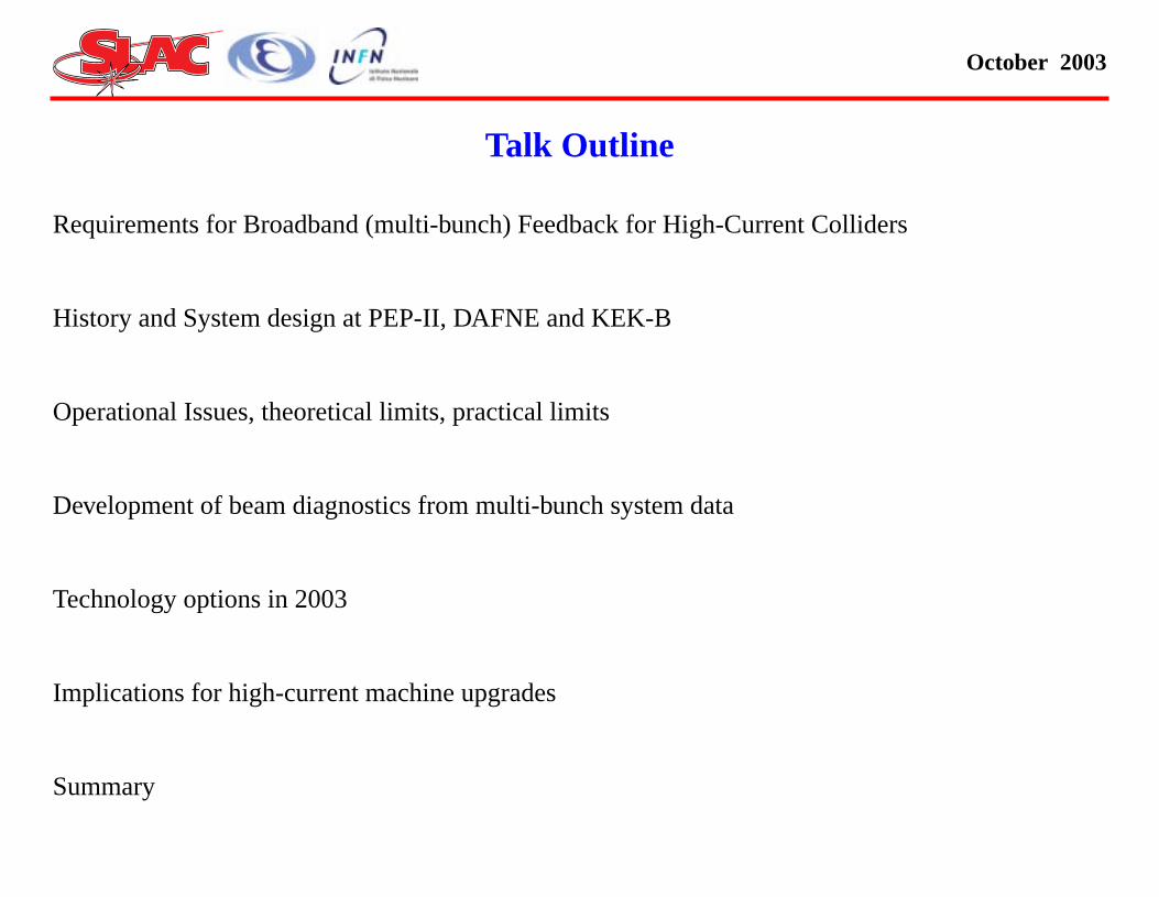
CESR Transverse Feedback
. Rogers, M. Billing, et al
bunch spacing
are 5 tap FIR filter (70 ns cycle)
t normalization via look-up table
duty-cycle modulator explored

October 2003
Histo rtant technicalKB
SLAC nd all digital processingarchite t that time, it was decided:
Longit ocessing channel (where thedowns ate of 1/N revolutions). Thegener ommercial fixed-instructionDSPs
Transv we could not see a technicalmeans e transverse systems weredesign rated in betatron phase - thecorrec ayed by 1 turn. PEP-II useda digit y cables.
KEKB tap filter design suggestedby Fle iplication, though the filtercharac ut signal phase, are not asgener ion used full-custom GaAscircuit 32 filter channels.
ry of wideband coupled-bunch feedback, and impodecisions made by SLAC/LBL/INFN and KE
/LBL/INFN examined a mix of all-analog, hybrid analog/digital, actures in the original collaboration and study in the early 1990’s. A
udinal processing was best addressed via a downsampled digital prampling better matched the synchrotron frequency to a sampling r
al-purpose processing channel was implemented in an array of 80 c (the “farm”).
erse processing required a full-rate digital processing channel, andto implement a fully-programmable filter at the 500 MHz rate. Th
ed using a two-pickup front end, where the two pickups were sepation signal was computed via a scaled sum of the two pickups, delal delay mechanism - the ALS and smaller rings used analog dela
implemented a non-downsampled full rate digital filter, using a two-mming Pedersen. This approach only required addition, not multteristics (limited by DC offset constraints), and control of the outp
al purpose as a true FIR or IIR filter structure. The KEK implementatry to implement an 32 fold demultiplexer/multiplexer channel, with

October 2003
s
Front-
Gener
QPSK
High P
PEP-II/DAFNE/ALS Longitudinal System
End Phase Detection at 6*RF (3 GHz), DAFNE 3*RF
al-Purpose DSP farm (40 - 80 processors)
-AM output modulator (9/4, 11/4 or 13/4 * RF)
ower Stages 200 - 1500 W (1 - 2 GHz)
Kicker Structure
Comb Generator
Timing & Control
Beam Bunches
BPM
ExternalDriveInput
BunchError
Farm of DigitalSignal
Processors
QPSKModulator
Kicker Oscillator1.125 GHz
Phase-locked to Ring
Master OscillatorPhase-locked
at 6*RF of Cavity
Poweramp
Ho
ld-B
uff
er
D/A
A/D
Do
wn
sam
ple
r
DSP
X Low-pass Filter
10-96 8146A1
+

October 2003
DAFN
• in
• qinind
We imcontro
• sth
• twd
• qsuin
The fle function without anychang
80 100 120
DualNotch
80 100 120
Quadrupole instability control
E e+/e-collider at LNF
creased operating currents
uadrupole mode longitudinalstabilities have appeared (thestalled system suppresses theipole modes).
plemented a novel quadrupolel filter
oftware programmability ofe DSP farm
o parallel control paths foripole and quadrupole modes.
uadrupole control has beenccessful, allowing a 20%crease in luminosity.
xibility of the software-configured control scheme allows this newes in the installed hardware.
0 20 40 60
−40
−20
0
20
40
Frequency (kHz)
Gai
n (d
B)
0 20 40 60−200
−100
0
100
200
Frequency (kHz)
Pha
se (
deg)

October 2003
hannel
A. Dra
Featu
Digita
BPM p hase shift and lattice
DAFNE Transverse Feedback Processing C
go, et al
res - slow DC offset (orbit offset) removal
l delay, plus cable delay
ickups selected from set depending on machine tune for proper p

October 2003
tation
From
ALS h s and hybrids
Quadr phase selection
ALS/PEP-II Transverse Feedback Implemen
W. Barry
as Analog 2-tap FIR filter for DC orbit suppression via delay cable
ature processing via 2 pick-ups, scaled and summed for gain and

October 2003
cessing
from M
2 ns b
2-tap
32 pa
KEK-B Transverse and Longitudinal signal pro
. Tobiyama, et al
unch spacing
FIR structure (fixed 1, -1 coefficients, no multiplier)
rallel channels

October 2003
Transv
Essen aseband (except for KEK-B, usin
Corne ating beams. Also a designusing plifier drive, was explored
Amplifi
Longit
Ceram
Loade SY, PLS, (KEK-B). Easyto coo kers in design/fabrication
Drift-tu ed by ALS, (PLS), PEP-II.Usefu
Opera WT power stages (200 W)
Some ltiple amplifiers
Kicker Implementations
erse-
tially all striplines. Length limited by bunch spacing. Operation at bg two sets of kickers/amplifiers)
ll (CESR) has clever short-circuited design to kick counter-propaga clever duty-cycle modulated kicker driver, as apposed to linear am
ers - baseband (100kHz - 230 MHz)
udinal - Several designs
ic Gap (UVSOR) - modest shunt impedance
d (damped) Cavity - Designed by LNF-INFN, used by DAFNE, BESl. Needs circulator. Reasonable shunt impedance. New PEP-II kic
be structures - designed by LBL Beam Electrodynamics Group, usl in-band directivity. Cooling issues for ampere currents
ting in 1 - 1.5 GHz band. GaAs power amps (200 - 500 W), also T
installations (e.g. PEP-II) use multiple longitudinal kickers with mu

October 2003
LFB/T d maximum synchronousphase
Sever
• Gro erse case)
• P
• P
• Gro rtant for large machines)
• P
• D
• D
• Syn cosine detection)
• D
• D
• In l gap voltage
Stability requirements for the LFB/TFB
FB have limitations on the maximum controllable growth rates an transients
al effects need to be considered to determine LFB/TFB stability
wth rates due to the HOM impedances (and resistive wall in transv
roportional to the number of installed RF cavities
roportional to the beam current
wth rates due to the fundamental impedance (LFB only, most impo
roportional to the number of installed RF cavities
epend on the beam current (non-linearly)
etermined by the low-level RF configuration
chronous phase transient due to the gap (LFB sine detection, TFB
epends on the size of the gap ( )
epends on the gap voltage per RF cavity ( )
other words depends on the number of powered cavities and tota
∆φs Lgap∼
∆φs 1 Vc⁄∼

October 2003
ol
What ance)?
Sever
I). Noi several stages -
Front E namic range, steady-stateoffsets
Proce oise (broadband) is onesystem ibute. Narrowband filtershelp w nsitivity to machine tunes,opera
Power expensive way to increasegain (m
Outpu scillation amplitude fromwhich mplicated
Ultimate/Practical Limits to Instability Contr
Limits theMaximum Gain(e.g. fastest growth rate, or allowed imped
al Mechanism
se in feedback filter bandwidth, limits on noise saturation. Gain is from
nd (BPM to baseband signal) gain limited by required oscillation dy (synchronous phase transients, orbit offsets)
ssing Block - gain limited by noise in filter bandwidth. Quantizing n limit - noise from RF system or front-end circuitry may also contrith broadband noise. Broad filter bandwidths help with reduced se
ting point - or variations of dynamics with current
stages - gain scales with kicker impedance, sqrt(output power). Anore kickers, more output power).
t power (actually maximum kicker voltage) determines maximum o linear (non-saturated) control is possible. Saturated behavior is co

October 2003
art II
II) Sta s. control frequency)
Ultima cessing, and actuator
For cir pickup)
limit se ver control band
Appro
L
R
U
Negat for causal systems you paythe pr
Ultimate/Practical Limits to Instability Control, p
bility of the feedback loop itself, (e.g. limits on phase shift and gain v
te Limits (loop stability) Related to time delay between pickup, pro
cular machines (systems with kick signal applied on later turn than
t by revolution time, fastest growth rates, and filter phase slope o
priate for optimal control theory applications
QR
obust Control
ncertain Systems
ive group delay over a portion of the frequency band is possible, butice in increased phase slope away from the negative slope region

October 2003
Instab
• Maxtota
• Maxdamstab
• LFBmax
• Noisnot C Offset issues?
• Tran ontrol. The sensitivity canbe r allowed perturbations
Synch
• FronRan 0deg
• Fron
−0.5 0 0.5ℜ(p) (ms−1)
bunches; 1580 mA; λ = 0.3 ms−1
−20 −10 0 10 20−1
−0.5
0
0.5
1
Phase offset (deg@RF)
Nature of the PEP-II LFB/TFB limitations
ility growth rates
imum stable loop gain - depends on controller design,l loop delay. LFB runs FIR/IIR, TFB quad shifter
imum usable loop gain - gain that provides the largestping. Depends on the same parameters as the maximumle gain, but is significantly lower
Feedback systems in PEP-II are currently running nearimum usable gain. TFB? Gain limit from noise or DC?
e floor at the ADC - depends on RF-driven noise level,a problem for the PEP-II LFB in the current configuration. TFB? D
sient sensitivity - effect of injection and RF feedback transients on ceduced by increasing kicker voltage. Back-end power determines
ronous phase transients (gap transients)
t-end of the LFB uses a phase detector at 6th harmonic of the RF.ge of detectable signals is 180 degrees peak-to-peak at (or 3rees peak-to-peak at RF).
t-End of the TFB at 3rd harmonic - cosine detection
−1.5 −12.5
3
3.5
4
4.5
ℑ(p
) (k
Hz)
PEP−II LER: 729
6 f RF×

October 2003
Origin
• E• Id design currents• B
Secon
• P e machine measurements(g commissioning data)
• b or, bunch power spectrum(n
• S andau damping - instabilityth
• C nous phases, tune shifts• E• T
In som ost useful and significantbenefi systems.
Evolution of DSP-based Diagnostics
al motivation - stabilize coupled-bunch instabilities
ngineering-level system checksentification of unstable eigenmodes, growth/damping rates at full eam Pseudospectra, Grow/Damp Modal Transients
d-tier diagnostics
redictions of high-current unstable behavior from low-current stablrowth/damping rates at design current estimated from low-current
eam instrumentation - bunch by bunch current monitor, tune monitoise) monitorynchrotron tune vs. bunch number - gap transients, tune spread, Lresholds for various configurationsomplex Longitudinal impedance vs. frequency from bunch synchroigenstructures of uneven fills, phase space trackingransverse Motion via DSP Data Recorder/Control
e ways the development of the beam diagnostics has been the mt of the use of the programmable technology in the DSP feedback

October 2003
PE igh currents
A para
Fastesdrivenfundam
Tune swe no
With aeasiermode
In genthe infundamfasterby HO
Theimpedhavingthese“woofe
0
5
0 Time (ms)
b) Evolution of Modes
154 1156 1158 1160Mode No.
Growth Rates (pre−brkpt)
hifGain= 3, Nbun= 1160,kpt= 30, Calib= 10.06.
P-II HER Longitudinal instability growth rates at h
sitic study at 1100 mA
t growing mode is mode -3by the RF cavity
ental mode.
hifts follow the general shapermally see in simulations
2.5% gap the data is muchto analyze since there is lesscoupling.
eral, for longitudinal motion,-cavity modes (from theental) are roughly 10 times
than the HOM modes drivenM’s in the cavities.
LLRF configurations, andance control, are critical in
adequate margin to controllow modes. We use ther” for extra gain.
0
5
200400
600800
1000
0
0.5
1
1.5
Time (ms)
a) Osc. Envelopes in Time Domain
Bunch No.
deg@
RF
500
1000
0
0.2
0.4
Mode No.
deg@
RF
1152 1154 1156 1158 11605.2
5.3
5.4
5.5
5.6
Mode No.
Fre
quen
cy (
kHz)
c) Oscillation freqs (pre−brkpt)
1152 10
0.2
0.4
0.6
0.8
1
1.2
1.4
Rat
e (
1/m
s)
d)
PEP−II HER:jun1903/021609: Io= 1099.45mA, Dsamp= 6, SGain1= −0.9, Gain2= 0, Phase1= −140, Phase2= −140, Br

October 2003
PEP-I
– B 0 revolution harmonics– C chrotron sidebands around
th– A ncy feedback signal is
e in for the lowest modes
KEK-B o the ARES energy storagecavity lties with the fundamentaldetuni ontrol loop is used. Futurecurren
DAFN broadband feedback tocontro e cavity detuning is lesseffecti equency was dropping thefilter p er IIR filter.
PLS, B a tight tolerance on masteroscilla nt requires a very carefulspecifi Y/DAFNE)
Longitudinal Mode Zero Control
I is unique, in that the RF system has
roadband RF feedback, which spreads the RF fundamental over 2omb-filter RF feedback, to reduce the residual impedance at the syne revolution harmonics within the bandwidth special “Woofer” link with the feedback, in which the lowest frequequalized and injected back into the RF, increasing the feedback ga
uses both superconducting and room temperature RF cavities, alson the room temperature RF cavities. This helps reduce the difficung driving low negative longitudinal modes - a dedicated mode -1 ct upgrades will likely also need control of mode -2, etc.
E has a mode zero RF feedback loop (analog), independent of thel mode zero at high-currents where the Robinson damping from thve (this was a problem running the FIR filters, as the mode zero frhase began to create positive feedback). Better control with a flatt
ESSY - mode zero controlled through broadband feedback - setstor phase noise. Shift in mode zero oscillation frequency vs. currecation of the control filter (special IIR designs in use at ALS/BESS

October 2003
tion
Longitudinal Model and Experimental Verifica
October 2003
nitoring
Both th um components and cables,feedth ponents additionally haveflowsw
PEP-I eedthroughs.
The L
Amplifi abort)
Load p rs which are logged by theopera
A spec a graduate student project,but ne e load power level went upor dow aborts or other fast beamloss. M
Both L e power amplifiers to reduceout-of -style longitudinal kickerswill re
Upgrades and High-Current Heating issues, mo
e PEP-II TFB and LFB have numerous thermocouples on the vacuroughs and some high-power loads. The water-cooled comitches to monitor water flow.
I has had cable fires, arcing and destruction of high-power kicker f
FB also has high-power monitoring in:
er reverse power meters and protection trip circuits (causes beam
ower monitoring via directional couplers and diode power detectotions group.
ial load power derivative trip circuit was designed and fabricated asver commissioned. Idea was to have fast (sub millisecond) trip if thn rapidly. Had to gate the trips with current to not trigger on beamight be worth commissioning this.
FB and TFB have filters between the beam-line components and th-band power going backwards into the amplifier outputs. New Cavityquire circulators, likely in addition to the existing absorptive filters.

October 2003
The la chipsets, special DSP EPLDdevice esign tools.
The R munications markets hasoffered unctions (amplifiers,modul
Treme
#1) Co s in the most popularcomm
#2) Co ature product lines, leavingsome
#3) Co , availability concerns fordesign es to accelerator design-comm
Technologies and Options
st decade has seen explosive development of general purpose DSPs, and extensive commercial development of DSP software and d
F and microwave circuit technology developed for wireless telecom an unprecedented array of monolithic and highly integrated RF f
ators, mixers, etc.)
ndous opportunities, and some pitfalls
mmercial pressures have produced some very integrated functionunications bands- but only in specific frequency bands
mmercial pressures have forced some manufacturers to abandon mtraditional frequency bands and functions with limited choices
mmercial pressures have brought on rapid product obsolescenceed-in functions. A very poor match of commercial product life cyclissioning- operation cycles

October 2003
500 M
Recon Xilinx Virtex-II series)
These d processing architecturecould ontrol problems at a rangeof circ easurement, impedancemeasu verse HOM impedancecharac
Throu essing blocks would bepipelin
nx)
Promising Areas for Research
s/sec. to 1.5 Gs/sec. Digital Signal Processing
figurable EPLD functions with DSP cores, built-in RAM functions (
developments suggest that a general-purpose, software configurebe developed, with applications to many feedback and instability cular machines. Applicability to many dynamics diagnostics (tune mrements, tune vs. bunch number, trajectory measurements, transterization, bunch by bunch current measurements, etc.)
ghput of 1 Gs/sec. does not mean 1 ns of group delay - such proced, with significant time delay from input to output.
Function Performance (from Xili
MACs per second 600 Billion
FIR Filter - 256-tap, linearphase, 16-bit data/coefficients
180 MSPS@180 MHz
FFT - 1024 point, complex data,16-bit real & imag. output
<1 s@140 MHzµ

October 2003
Very lo
Such est possible group delay(throu
Applic
One fu sition vs. bunch number insingle l derived from initial beam-beam er the rest of the trains intocollisio
Specu hich correct within a turn,using is less than the harmonicnumbe nches based on modalinform e a fast channel, combinedwith a ack.
Likely rogrammable, in that anadapti lowly to converge on anoptimu
Promising areas for research, II
w group delay processing blocks
functions would still use a basic FIR/IIR topology, but have the lowghput delay).
ations to feedback, feed-forward systems
ture application - stabilization of transverse offsets or transverse po-pass colliders with trains of bunches. Basic idea - use error signadeflections to rapidly compute a feed-forward correction used to sten.
lative application - instability control systems for circular machines werror information from bunch N to correct on bunch N+M, where Mr. The error filter would be essentially estimating motion of the bu
ation and motion detected from the bunches. Also it is possible to us fast cable plant that cuts across the ring for low group delay feedb
implementations are electro-optic. Such systems should also be pve controller might adjust the feedback filter(s) or tap weightings sm correction filter.

October 2003
Develo
Any fe th limitations restricting useto dipo
Highe cillations
(intere upole longitudinal modesindepe
Develo high-power RF and kickersignal
Existin um power GaAs FETtechno
Existin ponents might not be up tohigher
Promising areas for research, III
pment of wideband Actuator (kicker) structures
edback scheme requires actuators - existing kickers have bandwidle modes, finite gains and all have power level restrictions.
r bandwidth devices could control quadrupole, higher modes of os
sting use of finite bandwidth kicker to control both dipole and quadrndently demonstrated at DAFNE)
pment of high power RF amplifiers for actuators, development of delivery components
g approaches use costly power amplifiers based on parallel medilogy
g vacuum kicker components, feedthrough and power cabling com-current upgrades in terms of beam induced heating

October 2003
Do we
We thi
Sever ates above 1 GHz.
• Pho superconducting 1.3 GHzRF
• IR r
• PEP
Even f et two samples per bunch.
• I&Q
• Sup
2003 t ial dedicated DSP functions
• High
• high
• des
Technology options in 2003
really need 1 GSPS?
nk we really need1.5 GSPS!
al machines in design right now are considering bunch repetition r
toinjected Energy Recovery Linac design at BNL is using TESLA cavities.
ing at LBNL is considering 1-1.5 GHz RF.
-II is considering upgrade to 952 MHz RF
or the 500 MHz and lower RF frequencies it is useful to be able to g
detection using a single ADC
porting a dual pickup transverse front-end
echnology supports very high-speed FPGA architectures, with spec
speed logic
speed multipliers as function block
ign tools for DSP functions

October 2003
ns
We (S al processor as a singleVME6
• T thers
• L l
• T ing rate measurements)
• F monitor, tune monitor, gaptr
• S
The b g using two pickups (e.g.quadr ift of kick)
The fa e I&Q front end processing(resea
This c y of signal processing andinstrum gorithm. With the 1.5 GHzsampl celerator processing needs,includ ht sources, and severalrecircu
Gboard Processing Channel Specificatio
LAC/KEK/LNF) are designing a general-purpose feedback sign4X module:
ransverse bunch-by-bunch control at KEKB, PEP-II, DAFNE and o
ongitudinal bunch-by-bunch control at KEKB, PEP-II, DAFNE, et a
ransient-domain diagnostics features (e.g. instability growth/damp
ast bunch and beam instrumentation (e.g. bunch by bunch currentansient/synchronous phase measurement)
upport bunch spacings down to 0.66 ns - sampling at 1.5 GHz.
aseband processing channel is useful for transverse processinature pickups) or single pickup approaches (filter adjusts phase sh
st sampling rate can implement two sample/bunch processing for trurch follow-on efforts)
ore function is general purpose, and re-configurable into a varietent functions - the reconfigurable Xilinx FPGAs define the exact al
ing rate this core function would be applicable to several other acing NLC damping rings, numerous existing and proposed liglating linac proposals.

October 2003
Cont.
The b ed parallel processor, withsingle c processing, as in a storagering, w past history of channel N.Howev of functions, including apromp peline delay in the A/D andproces
• S en numbers?).
• In nsverse feedback.
• D
• S r filters
• S
• S
In long tter filter out the broadbandnoise, sampling by 30 has 15 turn(0.5 s ter) - a total of 105 turns.Runni rns. Of course, this extracompl
Gboard Processing Channel Specifications,
asic structure of the processing channel is a high speed multiplexinput and output channels. The architecture is optimized to do cyclihere the computation of the output for channel N depends on theer, the re-configurable Xilinx gate arrays could support a varietyt high-speed feedback/feedforward channel, consistent with the pising stages.
upport arbitrary harmonic numbers (may be OK to support only ev
dependent processing for all bunches on all turns - required for tra
iagnostic memory capable of holding 20 ms of data at the full rate
upport downsampled processing - reuse the hardware to get longe
upport downsampling for diagnostics for studying slow events
upport long FIR or IIR filters
itudinal feedback non-downsampled processing allows one to bereduces loop delay somewhat. For example, the processing down
ample) delay added to the filter group delay (90 turns for 6 tap filng the same filter at full rate (180 taps!) the delay is only 90 tuexity requires more computational resources.

October 2003
el• N
co
• ScoIIlig
• T
• Lco
• H(1th
• Bind
• Spp
16DAC
Bus
inte
rfac
e
Aout
Mul
tipl
exer
GBoard 1.5 GS/sec. processing channext-generation instabilityntrol technology
LAC, KEK, LNF-INFNllaboration - useful at PEP-
, KEKB, DAFNE and severalht sources.
ransverse instability control
ongitudinal instabilityntrol
igh-speed beam diagnostics.5 GS/sec. sampling/roughput rate)
uilds on existing program instability control and beamiagnostics.
ignificant advance in therocessing speed and densityreviously achieved.
DataAddr1Mx18
Data1Mx18Addr
DataAddr1Mx18
Data1Mx18Addr
DataAddr1Mx18
Data1Mx18Addr
DataAddr1Mx18
Data1Mx18Addr
20
20
32
32
18
18
18
20
18
2018 18
FPGA 2
FPGA 3
ADC
FPGA 1
16
18
18
32
32
32
FPGA 0
Ain
Dem
ulti
plex
er
32
32
32
LVTTL control bus
LVPECL @ 500(750) MHzLVPECL @ 71.4(107) MHz

October 2003
Basebprocesmodul
DataVirtex-
Eachuneveand 1GSPS
Use X
•
• 3
• 1
Each512K
Systemtransiedata r
1
Hardware descriptionand architecture with 1.5 GHz maximumsing rate implemented as a single VME64Xe.
Flow Processing is implemented in 4 XilinxII FPGA devices.
chip handles 4 data samples in parallel. Withn stepping parallel stream alternates between 164 samples (94-107 MHz clock rates at 1.5).
ilinx Virtex-II FPGA XC2V8000
CLB array
024 Kbits of RAM
68 multipliers - up to 210 MHz clock
FPGA controls two synchronous SRAMS ofx 36
can acquire 7 x 2 x 1M=14M samples ofnt data (worst case) - this corresponds to 14 ms
ecord at 1 GHz.
12 104×
18 18×

October 2003
ing
KEKB
Table
In cas ake longer FIR filters
DAΦNE
RF fre 368
Harm 120
Stepp 14 4@16, 4@14
Grou 8
Multip 42
FIR ppling,
26.3
Full I& 52.6
Example of PEP-II/KEK-B/DA ΦNE process
and PEP-II are the most processing intensive machines.
illustrates processing loads and limitations of the FIR algorithm.
e of DAΦNE multipliers can be used several times per sample to m
Table 1: PEP-II, KEKB, and DAΦNE processing
Parameter PEP-II KEKB
quency, MHz 476 508.9
onic number 3492 5120
ing selection 213@16, 6@14 320@16, 0@
ps per turn 219 320
lier limit on FIR filter taps 42 42
rocessing rate for I&Q sam- MHz
34 36.35
Q channel rate 68 72.7

October 2003
s
Our in d the critical high-speedsignal - what’s left to do?
Signa best use of the processingcapab
Rema
Contro
High-s
physic
(the p -level simulation)
Packa
Comp
Board gy (limits useful board size)
Front nitoring? Shutdown?
Initial on, front end and back-endfunctio ions?
Detailed Design and Development Issue
itial KEK-SLAC design collaboration has shown the feasibility, an processing channel is verified via functional and timing verification
l processing - verify functioning of downsampling features (that allowility for longitudinal processing in some situations)
ining tasks - the real detailed engineering
l interface, user interface
peed timing and clock distribution design
al layout, circuit PC board design, controlled impedance design
hysical layout, delays, skews, etc. are NOT simulated in the board
ging format - VME64X? 400 mm depth? What supplies to use?
onent choices - largely made. Issue of use of Triquint D/A?
size issues - density, thermal management, use of BGA technolo
panel - connectors? Monitor points or functions? Temperature mo
module prototype with baseband processing - use existing detectins as they are implemented. Later implement new VME64X funct

October 2003
The th ience running these multi-bunch eved success for the existingopera
Thein o the driving impedances.Runni rstand the practical limits ofthese
The te performance of thesesystem n gain and phase fromloop s nore.
PEP-I longitudinal modes, andhas s anagement of the kickerstructu
The d re very useful in validatingdynam ey also provide many veryunique edances). Theflexibilityof thes eds as the accelerators weremodifi ovel IIR control filters, orthe qu
The n r, more complex options.
Summary
ree factories (DAFNE, KEK-B and PEP-II) all have significant experinstability control systems. Each set of system designers has achi
ting currents
stabilitiesthemselves are proportional to current, and proportional tng these facilities at higher currents requires some analysis to undeinstability control systems.
chnology of these systems may evolve, but thefundamental limitsto thes, e.g. thesaturation effects from noiselimiting the gain, and the limits o
tability of the feedback loop, are the central limits we must never ig
I is pushing the group delay limits in the control of the low in-cavityome operational history with power dissipation and thermal mres.
iagnostics possible with the programmable DSP based systems aics and understanding the performance of the instability control. Thaccelerator diagnostics(such as measurement of complex HOM impe systems has been an opportunity to address several control ne
ed (such as the addition of harmonic cavities to the ALS, requiring nadrupole mode control at DAFNE)
ew technology in development (e.g. the Gboard effort) offers faste

October 2003
Thank M. Minty, C. Limborg, S.Prabh Young (SLAC), H. Hindi, I.Linsco cellini, M. Serio (LNF-INFN) an (LBL) for numerousdiscus
The P igned and developed by G.Oxoby designed and coded by R.Claus ytelman (SLAC)
The w eveloped by F. Voelker andJ. Cor lo, F. Marcellini, et.al.
Specia and to the ALS, SPEAR,PEP-I nd help.
W 6SF0051
Acknowledgments
s to D. Andersen, L. Beckman, P. Corredoura, N. Hassenpour,akar, W. Ross, J. Sebek, D. Teytelman, R. Tighe, U. Wienands, A.tt (Stanford), M. Tobiyama, E. Kikutani (KEK), A. Drago, F. Marand W. Barry, J. Byrd, J. Corlett, G. Lambertson and M. Zism
sions, advice and contributions.
EP-II digital processing architecture and modules were skillfully des, J. Olsen, J. Hoeflich and B. Ross (SLAC) - System software was (SLAC), I. Linscott (Stanford), K. Krauter, S. Prabhakar and D. Te
ideband longitudinal kicker for ALS and PEP-II was designed and dlett (LBL). The kicker for DAFNE was designed by R. Boni, A. Gal
l thanks to Boni Cordova-Grimaldi (SLAC) for fabrication expertiseI, and DAFNE operations groups for their consistent good humor a
ork supported by U.S. Department of Energy contract DE-AC03-7