Developing Tune Feedback for PEP-II Alan Fisher SLAC e + e – Factories 2003 October 13–16.
27
Developing Tune Feedback for PEP-II Alan Fisher SLAC e + e – Factories 2003 October 13–16
-
Upload
alaina-gibson -
Category
Documents
-
view
219 -
download
1
Transcript of Developing Tune Feedback for PEP-II Alan Fisher SLAC e + e – Factories 2003 October 13–16.

Developing Tune Feedbackfor PEP-II
Alan FisherSLAC
e+e– Factories 2003October 13–16

Tune-Tracker Concept
• Instead of whole spectrum, just follow the resonance.• Don’t use amplitude of peak.
– Dithering is required to identify a peak.– Peak height varies with current and luminosity.– Peaks often flat and broad when colliding.
• Use phase of beam’s response to sinusoidal shake.– Phase drops 180° as frequency scanned across peak.– Adjust frequency to find the middle of this resonance.– No dithering. Slope of phase provides a clear direction.– Little dependence on current or luminosity.

SR830 Lock-In Amplifier
• Stanford Research Systems digital lock-in amp:– Built-in sine-wave source (or use external reference).– Digital mixer and narrow low-pass filter to isolate signal
component at the reference frequency.– Finds amplitude and phase (relative to reference).– Remote control by GPIB.– Similar to our FFT spectrum analyzers, but one frequency at a
time.
• Tune-tracking loop controls lock-in through EPICS.– Computer sets frequency of lock-in, then reads back phase.

Lock-In EPICS Window

Frequency Scans
• Plots of magnitude and phase taken by stepping the lock-in through a frequency range around the tune peak.
• For finding the target phase and slope for tracking.• Target phase is midpoint of transition.• Curve fit performed around target phase.
– As wide a range as possible between blue cursors.– Chi-squared cut-off criterion to ignore big wiggles.
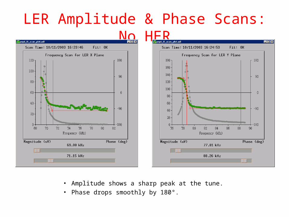
LER Amplitude & Phase Scans: No HER
• Amplitude shows a sharp peak at the tune.• Phase drops smoothly by 180°.

Frequency-Scan Control

Schematic of PEP-II Tune Tracker

Colliding away from x0.5LER x
HER y
LER y
HER x
Frequency (kHz)
Am
plit
ude
(µV
) Phase (degrees)

LER Scans in Collision with x0.51
• Amplitude: Tune spread creates long plateau and multiple peaks.
• Phase: No longer monotonic for x, which is near 0.5

HER Scans in Collision with x0.52

Pilot Bunches
• Broadening of spectrum in collision through beam-beam tune shift.– Hard to restore a previous high-luminosity setup, since the
midpoint moves higher as the luminosity is improved.
• Non-colliding bunches—“pilot” bunches—make a better reference.
• We add 4 pilots to the end of each ring’s fill pattern.• At our working point, with x just above 0.5, they are
closest to the resonance.– If these are safe, then the colliding bunches are safe too.– But we sometimes lose them on the half integer or the
synchrotron sideband above the half integer.
Gating the Pilot-Bunch Signals
• Measure the tune response from the pilots only.– A fast RF switch between the hybrids that form x (or y) and
the mixer directs the bunch signals into two streams.• Switches toggle once per turn.
– Start and stop times selected by ring timing channels.
– Separate mixers to process colliding- and pilot-bunch signals.– Colliding-bunch spectra displayed on spectrum analyzers.– Pilot-bunch outputs go to four tune trackers (one per tune plane)
and to another spectrum analyzer.– Tune trackers re-assigned to measure pilots rather than whole
train.

Downconverter Schematic

New Pilot-Bunch Downconverter

Switching between Excitation & Feedback
• Bunch-by-bunch transverse feedback strongly damps bunch motion.
• To get a good signal from a few pilot bunches:– Apply sinusoidal shaking from tune tracker.– Do not damp the shaking with transverse feedback.
• A fast RF switch (one per tune plane) toggles on every turn between shaking and damping.– Transverse feedback correction or sine excitation selected.

Pilot-Bunch Tests• Last spring, tune gating was set up and timed for the
HER and LER x planes only.• 4 pilot bunches with by-2 spacing were added to the end
of the HER and LER bunch trains (1000 bunches).– A strong response, with a very sharp tune transition typical of
non-colliding bunches.
• But pilot bunches were often lost on the 0.5 resonance.– Short lifetime for pilots.– Easily driven out by small tune tweaks. Nothing left to measure.– Will this improve when we have better control of beta beat?
• We re-introduced pilots in the last few days.– Several hours without trouble, but then...– We recovered more of last spring’s luminosity by raising the LER
current and lowering the x tune a bit.• LER pilots became hard to fill and had a short lifetime. Removed
pilots from fill pattern.

From Tune Tracking to Feedback• Adjust tune quads in response to tracker measurement.
– Feedback loop to hold tune constant.– Optionally, a more complex algorithm: Vary tunes with currents.
• Loop controlled in EPICS, but moves tune quadrupoles through “multiknobs” in older VMS (SCP) software.– EPICS more flexible; gives access to currents, loss of beam.
• Operators must use modified tune knobs.– Move feedback setpoints as well as quads.– Otherwise feedback would undo a knob tweak.
• When beam is lost, tune is knobbed to a no-beam setpoint for filling.
• Tested for several days in June.– Used whole train rather than vanishing pilots.– HER y feedback ran for days without trouble.

Feedback Flowchart
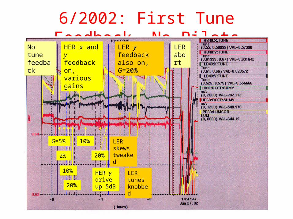
6/2002: First Tune Feedback, No PilotsNo tune feedback
LER y feedback also on, G=20%
LER abort
2%
20%
G=5%
10%
10%
20%
HER y drive up 5dB
LER tunes knobbed
LER skews tweaked
HER x and y feedback on, various gains

6/2003: Tune Feedback with LER x Pilots
• 2003 June 9• 10-hour plots of:
– Measured tune from tracker
– Quadrupole multiknob setting
– LER current
• Feedback on for 3.5 hours.– Intentional perturbations
applied, corrected automatically by feedback.
– Tune changes held within 0.0005 over 4 top-offs.
Test perturbations
LER x tune tracker
LER x tune knob
LER current
Feedback on

6/2003: Feedback with Trickle ChargeNo Pilots

Software for Vanishing Pilots
• New code written over the summer checks the bunch-current monitor to see if pilots are empty.
• Also looks for a minimum magnitude for the tracker’s response.
• Feedback is stopped if the pilots are too small.• Then the code seamlessly reverts to an older
feedforward algorithm.– Tunes are moved automatically in response to changes in HER
and LER currents, based on operator experience.
• After the pilots are refilled, the feedback takes over again.
• Code is ready for testing.

Tracker Main Window

Tracker Control Window

Feedback Control Window

Future Plans
• Near Term– Retime triggers for fast gates, due to new cabling.– Tune up the new mixer chassis for the pilots.– Test new code to see it shift from feedback based on pilot
bunches to feedforward based on total currents.– Find a way to avoid losing pilots.
• Let them collide a bit, with a small tune shift?
• Long Term– New hardware proposed for transverse feedback.
• New receiver, new digital delay with more bits.
• Should then incorporate the RF switches for damping/shaking.