PEP Ergo, PEP 10, PEP 20, PEP 30 Slab Props - PERI UABa3a26458-2120-4e76-bb04-9f1cc66bd19a/... ·...
38
PEP Ergo, PEP 10, PEP 20, PEP 30 Slab Props Edition 05 | 2015 Instructions for Assembly and Use – Standard Configuration
Transcript of PEP Ergo, PEP 10, PEP 20, PEP 30 Slab Props - PERI UABa3a26458-2120-4e76-bb04-9f1cc66bd19a/... ·...
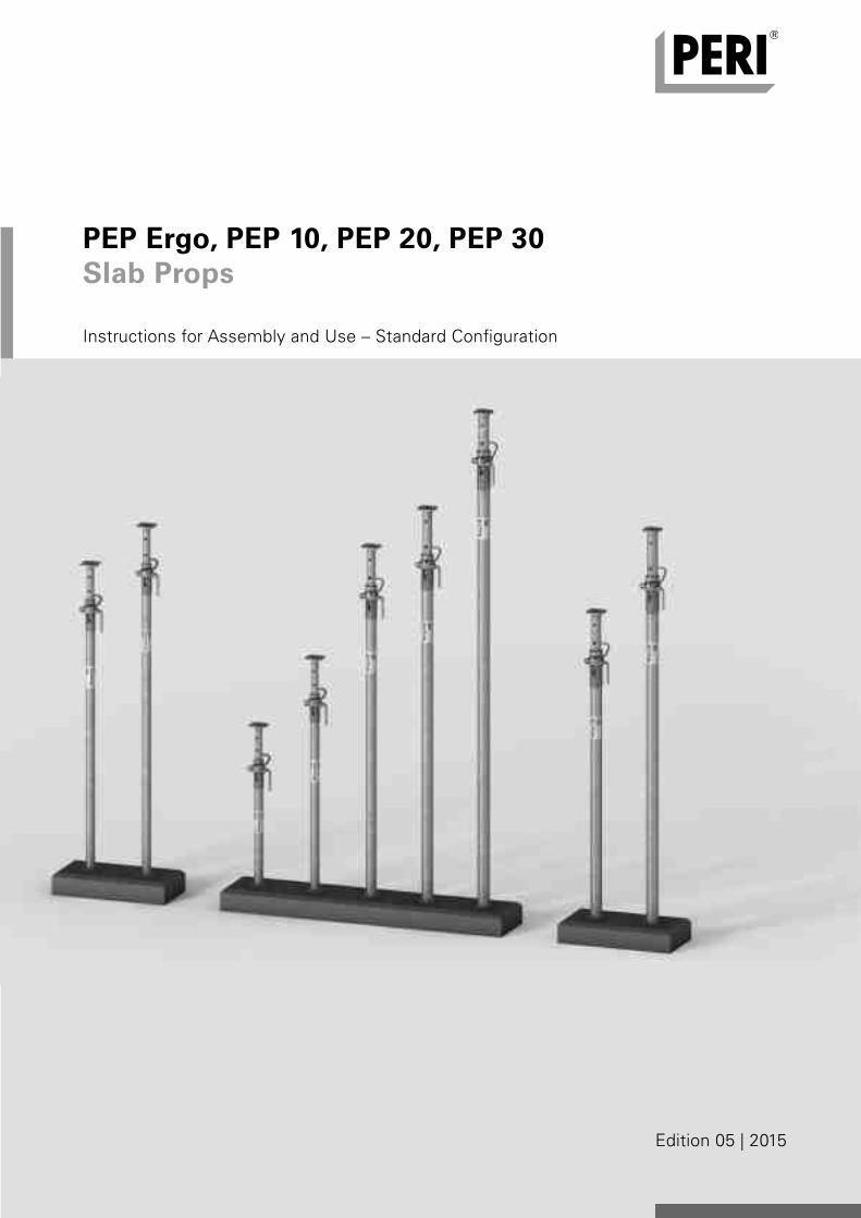
PEP Ergo, PEP 10, PEP 20, PEP 30Slab Props
Edition 05 | 2015
Instructions for Assembly and Use – Standard Confi guration
AuV PEP Deckenstutzen Export.indb 1 25.01.16 14:04
Introduction
Overview, Main components 1 Key 2 Intended use 3 Instructions for use 3 General safety instructions 4 System-specific safety instructions 5 Additional technical documentation 5 Standard configuration
A1 Assembly Pre-assembling the slab prop 6 Assembly with Tripod PEP Ergo 7 Assembly with Universal Tripod 8 Assembly with PEP Frame PRK 9
A2 Dismantling Releasing the Slab Prop under load 10
A3 Accessories Brace Clamp 11 Base MP 50 12
A4 Foreseeable misapplications 13
A5 Storage and transportation 16
Tables
Permissible prop loads PEP Ergo 18 PEP 10 21 PEP 20 22 PEP 20 with Base MP 50 23 PEP 30 24 PEP 30 with Base MP 50 25
Components
Components 26
PEP Slab PropsInstructions for Assembly and Use – Standard Configuration
Content
AuV PEP Deckenstutzen Export.indb 1 25.01.16 14:04
1
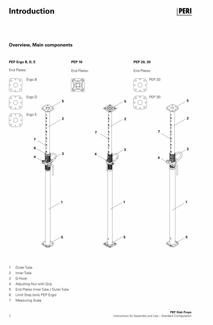
Overview, Main components
PEP Slab PropsInstructions for Assembly and Use – Standard Configuration
Introduction
1 Outer Tube
2 Inner Tube
3 G-Hook
4 Adjusting Nut with Grip
5 End Plates Inner Tube / Outer Tube
6 Limit Stop (only PEP Ergo)
7 Measuring Scale
PEP 20, 30
End Plates:
PEP 10
End Plates:
PEP Ergo B, D, E
End Plates:
6
2
3
5
5
1
4
7
3
5
5
1
4
7
2
3
5
5
1
4
7
2
Ergo B
Ergo D
Ergo E
PEP 20
PEP 30
AuV PEP Deckenstutzen Export.indb 1 25.01.16 14:04
2PEP Slab Props
Instructions for Assembly and Use – Standard Configuration
Introduction
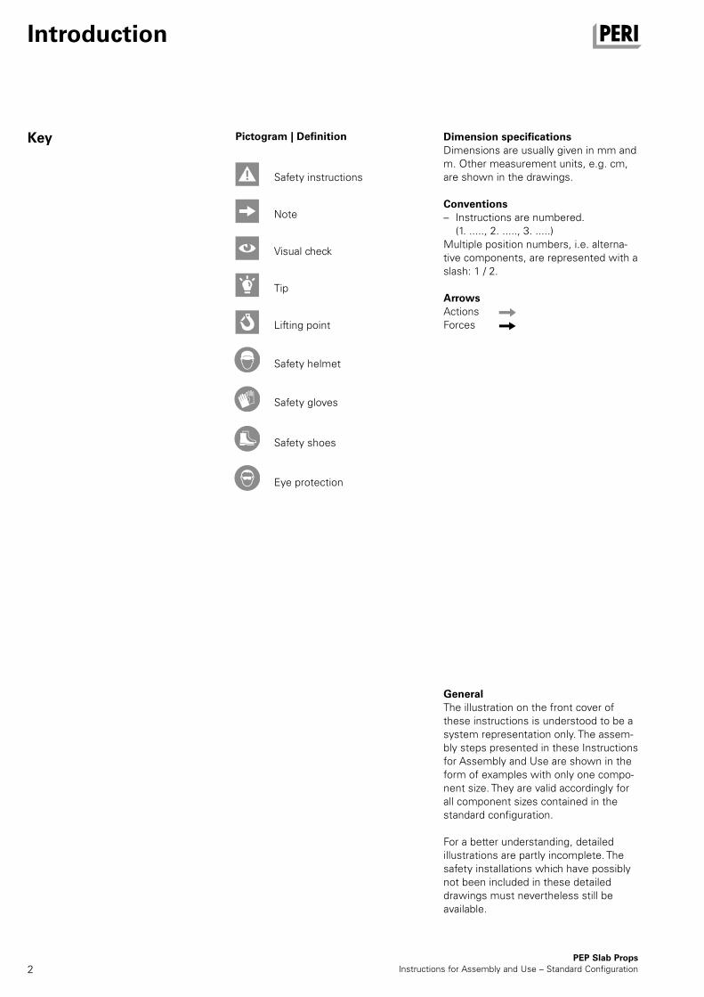
Key Dimension specificationsDimensions are usually given in mm and m. Other measurement units, e.g. cm, are shown in the drawings.
Conventions – Instructions are numbered.
(1. ....., 2. ....., 3. .....)Multiple position numbers, i.e. alterna-tive components, are represented with a slash: 1 / 2.
ArrowsActionsForces
GeneralThe illustration on the front cover of these instructions is understood to be a system representation only. The assem-bly steps presented in these Instructions for Assembly and Use are shown in the form of examples with only one compo-nent size. They are valid accordingly for all component sizes contained in the standard configuration.
For a better understanding, detailed illustrations are partly incomplete. The safety installations which have possibly not been included in these detailed drawings must nevertheless still be available.
Safety instructions
Visual check
Lifting point
Safety helmet
Safety gloves
Safety shoes
Eye protection
Note
Tip
Pictogram | Definition
AuV PEP Deckenstutzen Export.indb 2 25.01.16 14:04
3PEP Slab PropsInstructions for Assembly and Use – Standard Configuration
Introduction
GeneralThe use in a way not intended, deviating from the standard configuration or the intended use according to the Instruc-tions for Assembly and Use, represents a misapplication with a potential safety risk, e.g. risk of falling.
Only PERI original components may be used. The use of other products and spare parts is not allowed.
Changes to PERI components are not permitted.
FeaturesPEP Slab Props are used in shoring assemblies in a planned perpendicular position in order to transfer vertical loads. In particular, they also provide support for slab formwork systems.All components are galvanized. The overall length of the slab prop is stamped in 10 cm increments on the pegging holes on the inner tube. The adjustment range per marking is max. 12 cm.
Safe working conditions are guaranteed at all times through: – hand safety clearance, – anti-dropout safeguard on the inner
tube, – ergonomic and non-jamming G-hook.
PEP Ergo:The max. length of the slab prop is stamped in [cm] on the end plates. The length details are clearly legible on those slab props stored in pallets.
Technical data – Props according to DIN EN 1065 – Approvals
Z-8.311-899 Z-8.311-934 Z-8.311-941
– For load-bearing capacities, see Tables
Product descriptionPERI products have been designed for exclusive use in the industrial and commercial sectors by suitably trained personnel only.
PEP Slab Props – are steel slab props with an integrated
extension device, – correspond to the load requirements
of DIN EN 1065, – are used as vertical supports for
temporary constructions.
Intended use
Instructions for use
AuV PEP Deckenstutzen Export.indb 3 25.01.16 14:04
4PEP Slab Props
Instructions for Assembly and Use – Standard Configuration
Introduction
Safety instructions
GeneralThese Instructions for Assembly and Use serve as basis for the project-related risk assessment and the instructions for the provision and use of the system by the contractor. However, they do not replace them.
The contractor must ensure that the Instructions for Assembly and Use provided by PERI are available at all times for the users and that they are also fully understood. Safety instructions and permissible loads must be observed at all times.
For the application and inspection of our products, the current safety regulations and guidelines in the respective coun-tries where they are being used must be observed at all times.
In order to guarantee the safety against falling, the contractor must carry out a site-specific risk assessment based on these Instructions for Assembly and Use and the included safety and warning in-formation during each respective assem-bly, modification and dismantling proce-dure, as well as every time the system is used! Based on the risk assessment, appropriate measures regarding safety against falling are to be implemented on site!
The contractor must ensure that the personal protective equipment required for the assembly, modification or dismantling of the system is available and used as intended.
Materials and working areas are to be inspected on a regular basis especially before each use and assembly, and checked for signs of damage as well as stability and functionality. Damaged components must be exchanged immediately on site and may no longer be used.
The contractor has to provide safe work-ing areas for site personnel which are to be reached through the provision of safe access ways. Areas of risk must be cordoned off and clearly marked.
Safety components are removed only when they are no longer required.
The contractor must guarantee the stability during all stages of construction especially during assembly, modification and dismantling. He must ensure and prove that all loads can be safely trans-ferred.
Deviations from the standard configura-tion may only be carried out after a separate risk assessment has been completed by the contractor. On this basis, appropriate measures for the working and operational safety as well as the stability are to be implemented. Appropriate proof of stability can be provided by PERI if the risk assessment and measures deriving from this are readily available.
Components provided by the contractor must conform with the characteristics required in these Instructions for Assembly and Use as well as with all valid construction guidelines and standards. In particular, the following applies if nothing else is specified: – timber components: Strength Class C24 for Solid Wood according to EN 338.
– scaffold tubes: galvanised steel tubes with minimum dimensions of Ø 48.3 x 3.2 mm according to EN 12811-1:2003 4.2.1.2.
Scaffold tube couplings according to EN 74.
In the event of unfavourable weather conditions, e.g. – poor visibility (fog), – strong winds, – snow,
suitable precautions and measures are to be taken in order to ensure both work and operational safety as well as stability.
In case of extraordinary events which could compromise the safety, e.g. – storms, – earthquakes, – accidents, – longer downtimes,
the system must be comprehensively checked by a qualified person on behalf of the contractor regarding the work and operational safety as well as the stability. The results of the inspection are to be documented.
AuV PEP Deckenstutzen Export.indb 4 25.01.16 14:04
5PEP Slab PropsInstructions for Assembly and Use – Standard Configuration
Introduction
Safety instructions
System-specificRetract components only when the concrete has sufficiently hardened and the person in charge has given the go-ahead for striking to take place.
Anchoring is to take place only if the anchorage has sufficient concrete strength.
Care and maintenancePEP Slab Props have been designed for long-term use on the construction site. In order to maintain the value and opera-tional readiness of the PEP Slab Props for a long time, ensure that the Slab Props are carefully handled at all times.
Additional technical documentation
Storage and transportationDo not drop the components.
Store and transport components ensur-ing that no unintentional change in their position is possible. Detach lifting gear from the lowered units only if these are in a stable position and no unintentional change is possible.
During the moving procedure, ensure that components are picked up and set down so that unintentional falling over, falling apart, sliding or rolling is avoided.
Use only suitable load-carrying equip-ment to move the components as well as the designated lifting points.
During the lifting and moving procedure, ensure that all loose parts are removed or secured.
Assemble and move components on clean, flat and sufficiently load-bearing surfaces only.
Additional PERI product informationBrochures: – PEP Ergo Slab Props – PEP 10 Slab Props – PEP 20, 30 Slab Props
Instructions for use: – Pallets and Stacking Devices
PERI Design Tables
The structures shown in these Instructions for Assembly and Use are examples and feature only one prop type and component size respectively.They are valid for all types and component sizes contained in the standard configuration.
Instructions for Assembly and Use:Slab Formwork – MULTIFLEX – SKYDECK – GRIDFLEX
Slab Tables – TABLE MODULES – VARIODECK – SKYTABLE
AuV PEP Deckenstutzen Export.indb 5 25.01.16 14:04
6
2
4
7
3a4a
1 3
L1b
1a
PEP Slab PropsInstructions for Assembly and Use – Standard Configuration
A1 Assembly
Pre-assembling the slab prop
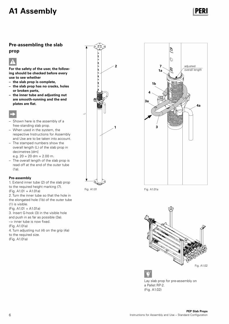
For the safety of the user, the follow-ing should be checked before every use to see whether – the slab prop is complete, – the slab prop has no cracks, holes
or broken parts, – the inner tube and adjusting nut
are smooth-running and the end plates are flat.
– Shown here is the assembly of a free-standing slab prop.
– When used in the system, the respective Instructions for Assembly and Use are to be taken into account.
– The stamped numbers show the overall length (L) of the slab prop in decimetres [dm] e.g. 20 = 20 dm = 2.00 m.
– The overall length of the slab prop is read off at the end of the outer tube (1a).
Pre-assembly1. Extend inner tube (2) of the slab prop to the required height marking (7). (Fig. A1.01 + A1.01a)2. Turn the inner tube so that the hole in the elongated hole (1b) of the outer tube (1) is visible. (Fig. A1.01 + A1.01a)3. Insert G-hook (3) in the visible hole and push in as far as possible (3a). –> inner tube is now fixed. (Fig. A1.01a)4. Turn adjusting nut (4) on the grip (4a) to the required size. (Fig. A1.01a)
Lay slab prop for pre-assembly on a Pallet RP-2.(Fig. A1.02)
Fig. A1.01a
Fig. A1.02
Fig. A1.01
adjusted overall length
AuV PEP Deckenstutzen Export.indb 6 25.01.16 14:04
7
8
8a
8b
8c
4a
8a
500 g
8b
8c
A1 Assembly
PEP Slab PropsInstructions for Assembly and Use – Standard Configuration
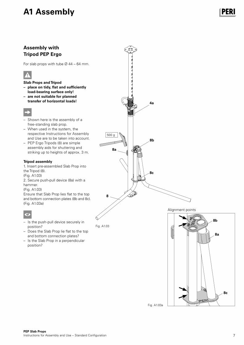
Assembly with Tripod PEP Ergo
For slab props with tube Ø 44 – 64 mm.
Slab Props and Tripod – place on tidy, flat and sufficiently
load-bearing surface only! – are not suitable for planned
transfer of horizontal loads!
– Shown here is the assembly of a free-standing slab prop.
– When used in the system, the respective Instructions for Assembly and Use are to be taken into account.
– PEP Ergo Tripods (8) are simple assembly aids for shuttering and striking up to heights of approx. 3 m.
Tripod assembly1. Insert pre-assembled Slab Prop into the Tripod (8).(Fig. A1.03)2. Secure push-pull device (8a) with a hammer.(Fig. A1.03)Ensure that Slab Prop lies flat to the top and bottom connection plates (8b and 8c).(Fig. A1.03a)
– Is the push-pull device securely in position?
– Does the Slab Prop lie flat to the top and bottom connection plates?
– Is the Slab Prop in a perpendicular position?
Fig. A1.03
Alignment points
Fig. A1.03a
AuV PEP Deckenstutzen Export.indb 7 25.01.16 14:04
8PEP Slab Props
Instructions for Assembly and Use – Standard Configuration
A1 Assembly
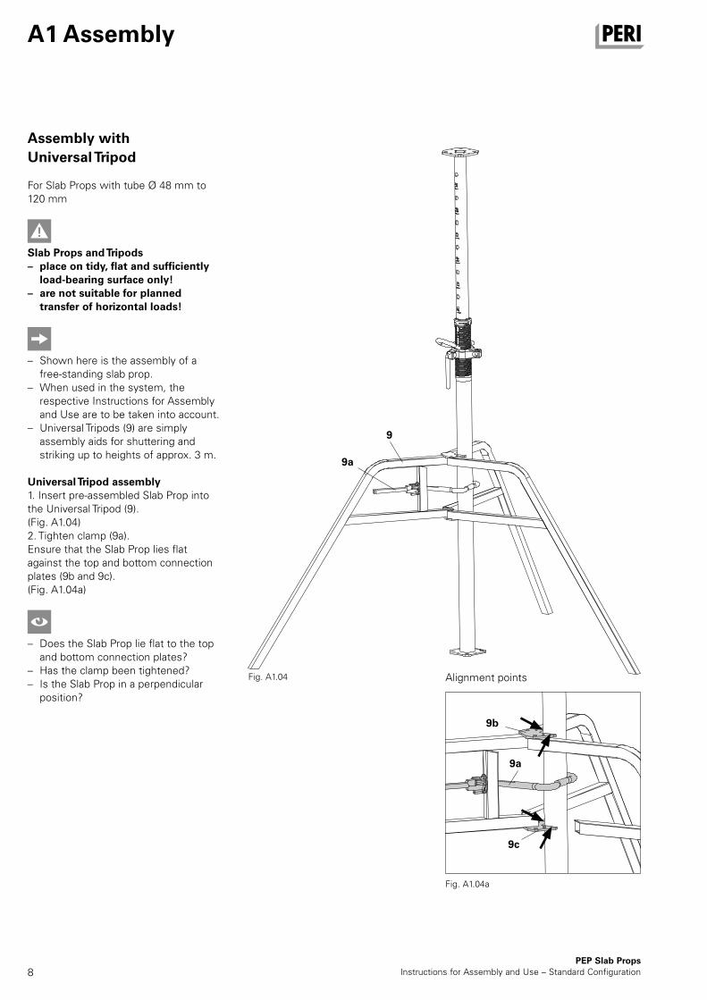
Assembly with Universal Tripod
For Slab Props with tube Ø 48 mm to 120 mm
Slab Props and Tripods – place on tidy, flat and sufficiently
load-bearing surface only! – are not suitable for planned
transfer of horizontal loads!
– Shown here is the assembly of a free-standing slab prop.
– When used in the system, the respective Instructions for Assembly and Use are to be taken into account.
– Universal Tripods (9) are simply assembly aids for shuttering and striking up to heights of approx. 3 m.
Universal Tripod assembly1. Insert pre-assembled Slab Prop into the Universal Tripod (9).(Fig. A1.04)2. Tighten clamp (9a).Ensure that the Slab Prop lies flat against the top and bottom connection plates (9b and 9c).(Fig. A1.04a)
– Does the Slab Prop lie flat to the top and bottom connection plates?
– Has the clamp been tightened? – Is the Slab Prop in a perpendicular
position?
Fig. A1.04a
9
9a
9b
9c
9a
Alignment pointsFig. A1.04
AuV PEP Deckenstutzen Export.indb 8 25.01.16 14:04
9
A1 Assembly
PEP Slab PropsInstructions for Assembly and Use – Standard Configuration
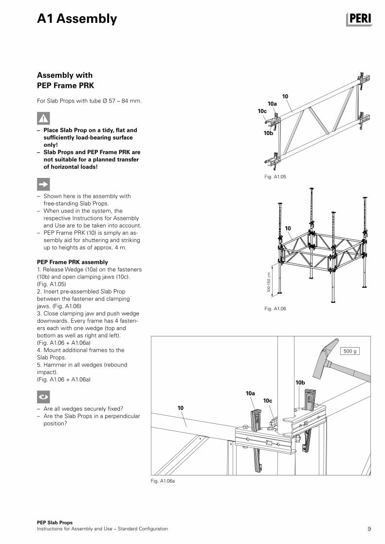
Assembly with PEP Frame PRK
For Slab Props with tube Ø 57 – 84 mm.
– Place Slab Prop on a tidy, flat and sufficiently load-bearing surface only!
– Slab Props and PEP Frame PRK are not suitable for a planned transfer of horizontal loads!
– Shown here is the assembly with free-standing Slab Props.
– When used in the system, the respective Instructions for Assembly and Use are to be taken into account.
– PEP Frame PRK (10) is simply an as-sembly aid for shuttering and striking up to heights as of approx. 4 m.
PEP Frame PRK assembly1. Release Wedge (10a) on the fasteners (10b) and open clamping jaws (10c). (Fig. A1.05)2. Insert pre-assembled Slab Prop between the fastener and clamping jaws. (Fig. A1.06)3. Close clamping jaw and push wedge downwards. Every frame has 4 fasten-ers each with one wedge (top and bottom as well as right and left). (Fig. A1.06 + A1.06a)4. Mount additional frames to the Slab Props.5. Hammer in all wedges (rebound impact).(Fig. A1.06 + A1.06a)
–
– Are all wedges securely fixed? – Are the Slab Props in a perpendicular
position?
Fig. A1.06
10
Fig. A1.06a
10a
100-
150
cm
10c
500 g
10b
Fig. A1.05
10
1010a
10b
10c
AuV PEP Deckenstutzen Export.indb 9 25.01.16 14:04
10
3.
3.
3.
2.
1.
2.
1.
2.
1.
1.
1.
4a
PEP Slab PropsInstructions for Assembly and Use – Standard Configuration
A2 Dismantling
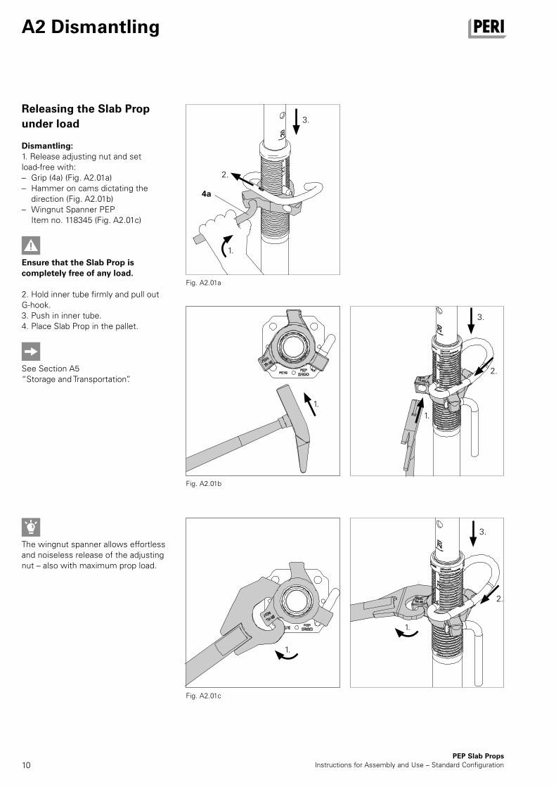
Releasing the Slab Prop under load
Dismantling:1. Release adjusting nut and set load-free with: – Grip (4a) (Fig. A2.01a) – Hammer on cams dictating the
direction (Fig. A2.01b) – Wingnut Spanner PEP
Item no. 118345 (Fig. A2.01c)
Ensure that the Slab Prop is completely free of any load.
2. Hold inner tube firmly and pull out G-hook.3. Push in inner tube.4. Place Slab Prop in the pallet.
See Section A5 “Storage and Transportation”.
The wingnut spanner allows effortless and noiseless release of the adjusting nut – also with maximum prop load.
Fig. A2.01b
Fig. A2.01a
Fig. A2.01c
AuV PEP Deckenstutzen Export.indb 10 25.01.16 14:04
11
A3 Accessories
PEP Slab PropsInstructions for Assembly and Use – Standard Configuration
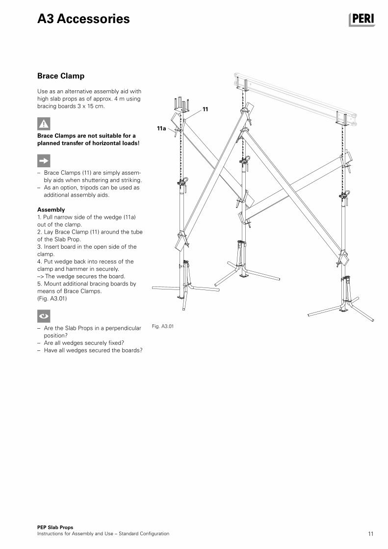
Brace Clamp
Use as an alternative assembly aid with high slab props as of approx. 4 m using bracing boards 3 x 15 cm.
Brace Clamps are not suitable for a planned transfer of horizontal loads!
– Brace Clamps (11) are simply assem-bly aids when shuttering and striking.
– As an option, tripods can be used as additional assembly aids.
Assembly1. Pull narrow side of the wedge (11a) out of the clamp.2. Lay Brace Clamp (11) around the tube of the Slab Prop.3. Insert board in the open side of the clamp.4. Put wedge back into recess of the clamp and hammer in securely.–> The wedge secures the board.5. Mount additional bracing boards by means of Brace Clamps.(Fig. A3.01)
–
– Are the Slab Props in a perpendicular position?
– Are all wedges securely fixed? – Have all wedges secured the boards?
Fig. A3.01
11
11a
AuV PEP Deckenstutzen Export.indb 11 25.01.16 14:04
12
12b
12a
1
12
PEP Slab PropsInstructions for Assembly and Use – Standard Configuration
A3 Accessories
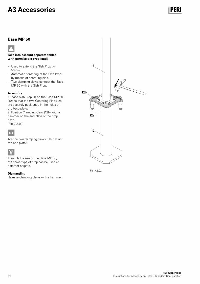
Base MP 50
Take into account separate tables with permissible prop load!
– Used to extend the Slab Prop by 50 cm.
– Automatic centering of the Slab Prop by means of centering pins.
– Two clamping claws connect the Base MP 50 with the Slab Prop.
Assembly1. Place Slab Prop (1) on the Base MP 50 (12) so that the two Centering Pins (12a) are securely positioned in the holes of the base plate.2. Position Clamping Claw (12b) with a hammer on the end plate of the prop base.(Fig. A3.02)
Are the two clamping claws fully set on the end plate?
Through the use of the Base MP 50, the same type of prop can be used at different heights.
DismantlingRelease clamping claws with a hammer.
Fig. A3.02
AuV PEP Deckenstutzen Export.indb 12 25.01.16 14:04
13
A4 Foreseeable misapplications
PEP Slab PropsInstructions for Assembly and Use – Standard Configuration
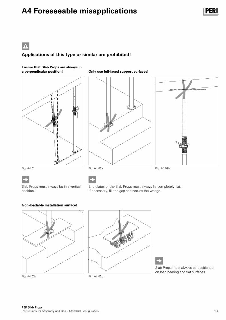
Ensure that Slab Props are always in a perpendicular position!
Fig. A4.01
Fig. A4.03a
Only use full-faced support surfaces!
Fig. A4.02a Fig. A4.02b
Fig. A4.03b
Slab Props must always be in a vertical position.
End plates of the Slab Props must always lie completely flat.If necessary, fill the gap and secure the wedge.
Slab Props must always be positioned on load-bearing and flat surfaces.
Applications of this type or similar are prohibited!
Non-loadable installation surface!
AuV PEP Deckenstutzen Export.indb 13 25.01.16 14:04
14PEP Slab Props
Instructions for Assembly and Use – Standard Configuration
A4 Foreseeable misapplications
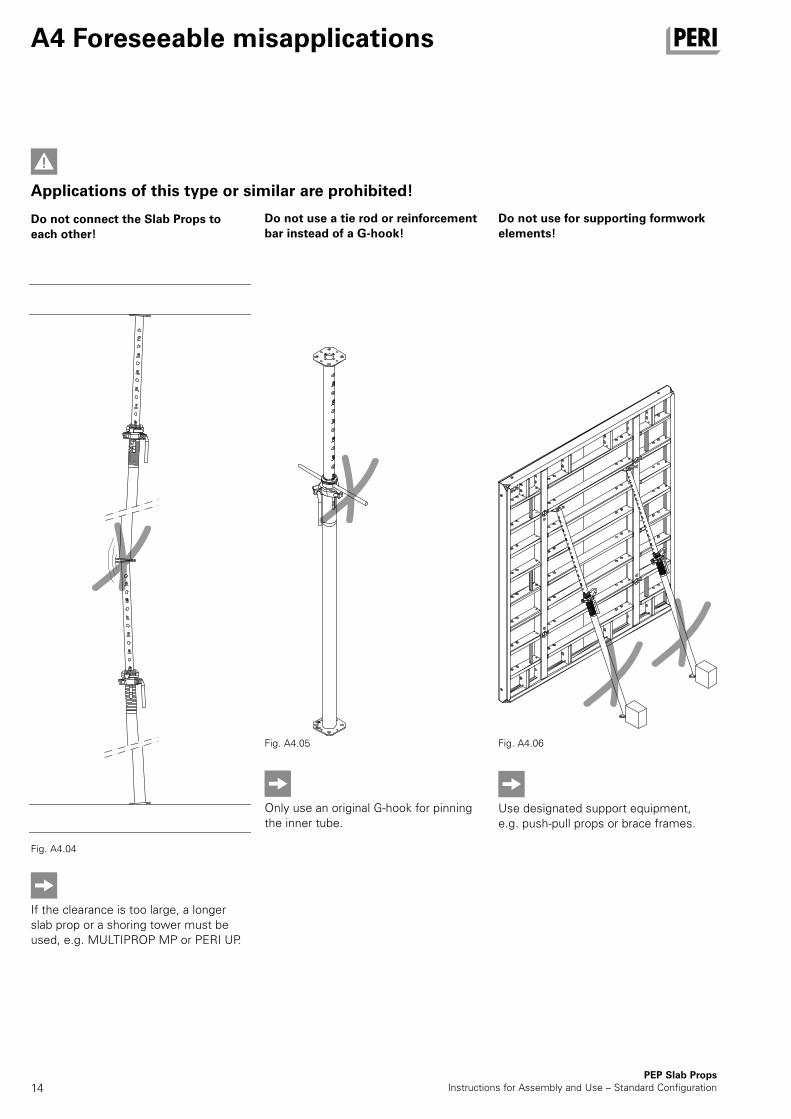
Do not connect the Slab Props to each other!
Do not use a tie rod or reinforcement bar instead of a G-hook!
Do not use for supporting formwork elements!
Applications of this type or similar are prohibited!
Only use an original G-hook for pinning the inner tube.
Fig. A4.05
Use designated support equipment, e.g. push-pull props or brace frames.
Fig. A4.06
Fig. A4.04
If the clearance is too large, a longer slab prop or a shoring tower must be used, e.g. MULTIPROP MP or PERI UP.
AuV PEP Deckenstutzen Export.indb 14 25.01.16 14:04
15
A4 Foreseeable misapplications
PEP Slab PropsInstructions for Assembly and Use – Standard Configuration
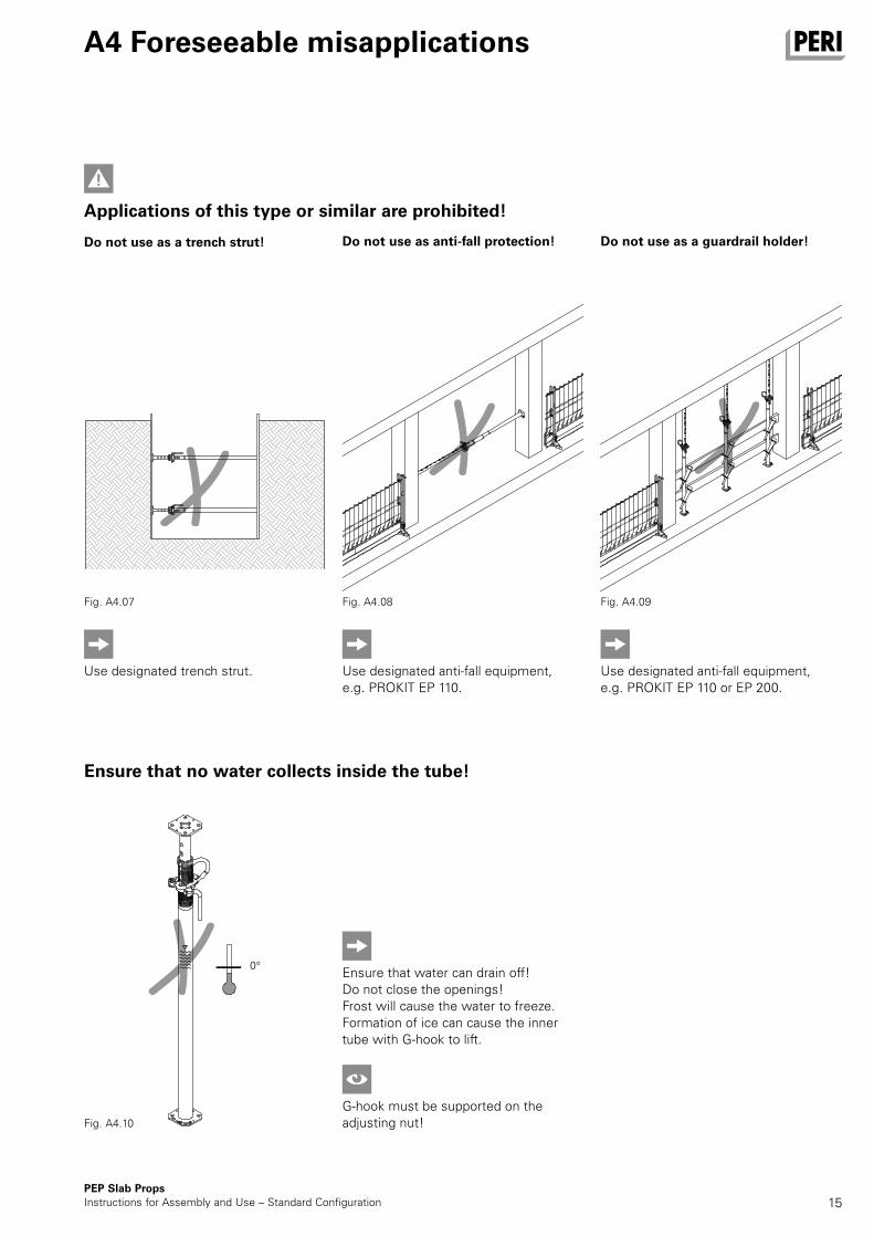
Do not use as a trench strut! Do not use as anti-fall protection! Do not use as a guardrail holder!
Applications of this type or similar are prohibited!
Use designated trench strut.
Fig. A4.07
Use designated anti-fall equipment, e.g. PROKIT EP 110.
Fig. A4.08
Use designated anti-fall equipment, e.g. PROKIT EP 110 or EP 200.
Fig. A4.09
Ensure that no water collects inside the tube!
Ensure that water can drain off!Do not close the openings! Frost will cause the water to freeze. Formation of ice can cause the inner tube with G-hook to lift.
G-hook must be supported on the adjusting nut!Fig. A4.10
0°
AuV PEP Deckenstutzen Export.indb 15 25.01.16 14:05
16
5c5b 5a
14
PEP Slab PropsInstructions for Assembly and Use – Standard Configuration
A5 Storage and transportation
Fig. A5.01
Fig. A5.01a
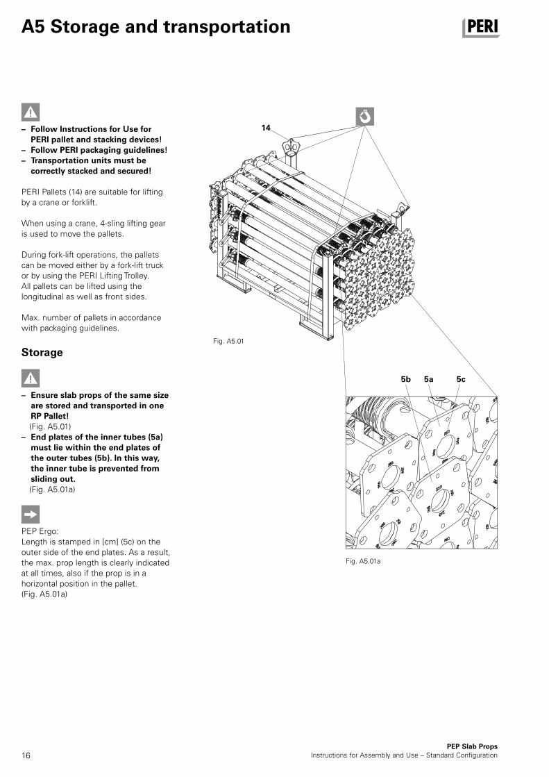
– Follow Instructions for Use for PERI pallet and stacking devices!
– Follow PERI packaging guidelines! – Transportation units must be
correctly stacked and secured!
PERI Pallets (14) are suitable for lifting by a crane or forklift.
When using a crane, 4-sling lifting gear is used to move the pallets.
During fork-lift operations, the pallets can be moved either by a fork-lift truck or by using the PERI Lifting Trolley. All pallets can be lifted using the longitudinal as well as front sides.
Max. number of pallets in accordance with packaging guidelines.
Storage
– Ensure slab props of the same size are stored and transported in one RP Pallet!
(Fig. A5.01) – End plates of the inner tubes (5a)
must lie within the end plates of the outer tubes (5b). In this way, the inner tube is prevented from sliding out.
(Fig. A5.01a)
PEP Ergo:Length is stamped in [cm] (5c) on the outer side of the end plates. As a result, the max. prop length is clearly indicated at all times, also if the prop is in a horizontal position in the pallet.(Fig. A5.01a)
AuV PEP Deckenstutzen Export.indb 16 25.01.16 14:05
17
A5 Storage and transportation
PEP Slab PropsInstructions for Assembly and Use – Standard Configuration
Transportation
– Ensure loads are correctly secured during transport!
– Use tension belts or steel bands.
The number of pallets that can be transported depends on the respective national transport regulations.
AuV PEP Deckenstutzen Export.indb 17 25.01.16 14:05
18
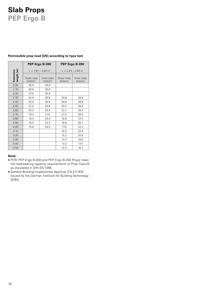
PEP Ergo B-300
L = 1.97 – 3.00 m
PEP Ergo B-350
L = 2.25 – 3.50 m
2.00 30.8 30.8
2.10 29.8 30.8
2.20 27.0 30.8
2.30 24.6 30.8 30.8 28.6
2.40 23.0 30.8 28.6 28.6
2.50 21.5 30.8 25.5 28.6
2.60 20.3 29.5 23.1 28.4
2.70 19.3 27.5 21.3 28.0
2.80 18.3 24.8 19.8 27.4
2.90 16.9 22.3 18.6 26.1
3.00 15.6 20.2 17.5 24.4
3.10 16.3 22.8
3.20 15.2 20.8
3.30 14.3 19.0
3.40 13.2 17.4
3.50 12.4 15.7
Permissible prop load [kN] according to type test
Ext
ensi
on
len
gth
[m
]
Outer tube bottom
Inner tube bottom
Outer tube bottom
Inner tube bottom
Note:■PERI PEP Ergo B-300 and PEP Ergo B-350 Props meet
the load-bearing capacity requirements of Prop Class B as stipulated in DIN EN 1065.
■General Building Inspectorate Approval Z-8.311-934 issued by the German Institute for Building Technology (DIBt).
Slab PropsPEP Ergo B
AuV PEP Deckenstutzen Export.indb 18 25.01.16 14:05
19
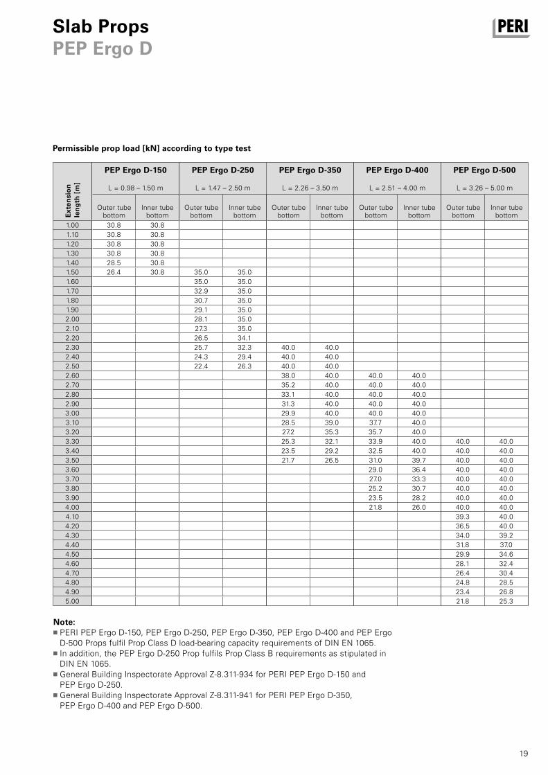
PEP Ergo D-150
L = 0.98 – 1.50 m
PEP Ergo D-250
L = 1.47 – 2.50 m
PEP Ergo D-350
L = 2.26 – 3.50 m
PEP Ergo D-400
L = 2.51 – 4.00 m
PEP Ergo D-500
L = 3.26 – 5.00 m
1.00 30.8 30.81.10 30.8 30.81.20 30.8 30.81.30 30.8 30.81.40 28.5 30.81.50 26.4 30.8 35.0 35.01.60 35.0 35.01.70 32.9 35.01.80 30.7 35.01.90 29.1 35.02.00 28.1 35.02.10 27.3 35.02.20 26.5 34.12.30 25.7 32.3 40.0 40.02.40 24.3 29.4 40.0 40.02.50 22.4 26.3 40.0 40.02.60 38.0 40.0 40.0 40.02.70 35.2 40.0 40.0 40.02.80 33.1 40.0 40.0 40.02.90 31.3 40.0 40.0 40.03.00 29.9 40.0 40.0 40.03.10 28.5 39.0 37.7 40.03.20 27.2 35.3 35.7 40.03.30 25.3 32.1 33.9 40.0 40.0 40.03.40 23.5 29.2 32.5 40.0 40.0 40.03.50 21.7 26.5 31.0 39.7 40.0 40.03.60 29.0 36.4 40.0 40.03.70 27.0 33.3 40.0 40.03.80 25.2 30.7 40.0 40.03.90 23.5 28.2 40.0 40.04.00 21.8 26.0 40.0 40.04.10 39.3 40.04.20 36.5 40.04.30 34.0 39.24.40 31.8 37.04.50 29.9 34.64.60 28.1 32.44.70 26.4 30.44.80 24.8 28.54.90 23.4 26.85.00 21.8 25.3
Permissible prop load [kN] according to type test
Ext
ensi
on
len
gth
[m
]
Outer tube bottom
Inner tube bottom
Outer tube bottom
Inner tube bottom
Outer tube bottom
Outer tube bottom
Outer tube bottom
Inner tube bottom
Inner tube bottom
Inner tube bottom
Slab PropsPEP Ergo D
Note:■PERI PEP Ergo D-150, PEP Ergo D-250, PEP Ergo D-350, PEP Ergo D-400 and PEP Ergo
D-500 Props fulfil Prop Class D load-bearing capacity requirements of DIN EN 1065.■ In addition, the PEP Ergo D-250 Prop fulfils Prop Class B requirements as stipulated in
DIN EN 1065.■General Building Inspectorate Approval Z-8.311-934 for PERI PEP Ergo D-150 and
PEP Ergo D-250. ■General Building Inspectorate Approval Z-8.311-941 for PERI PEP Ergo D-350,
PEP Ergo D-400 and PEP Ergo D-500.
AuV PEP Deckenstutzen Export.indb 19 25.01.16 14:05
20
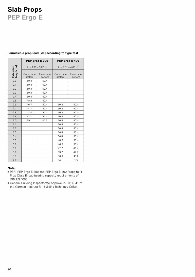
PEP Ergo E-300
L = 1.96 – 3.00 m
PEP Ergo E-400
L = 2.51 – 4.00 m
2.0 50.4 50.4
2.1 50.4 50.4
2.2 50.4 50.4
2.3 50.4 50.4
2.4 50.4 50.4
2.5 48.9 50.4
2.6 46.7 50.4 50.4 50.4
2.7 44.7 50.4 50.4 50.4
2.8 43.0 50.4 50.4 50.4
2.9 41.2 50.4 50.4 50.4
3.0 39.1 46.3 50.4 50.4
3.1 50.4 50.4
3.2 50.4 50.4
3.3 50.4 50.4
3.4 50.4 50.4
3.5 48.5 50.4
3.6 46.0 50.4
3.7 42.7 48.4
3.8 39.7 44.7
3.9 36.9 41.1
4.0 34.1 37.7
Permissible prop load [kN] according to type test
Ext
ensi
on
len
gth
[m
]
Outer tube bottom
Inner tube bottom
Outer tube bottom
Inner tube bottom
Slab PropsPEP Ergo E
Note:■PERI PEP Ergo E-300 and PEP Ergo E-400 Props fulfil
Prop Class E load-bearing capacity requirements of DIN EN 1065.
■General Building Inspectorate Approval Z-8.311-941 of the German Institute for Building Technlogy (DIBt).
AuV PEP Deckenstutzen Export.indb 20 25.01.16 14:05
21
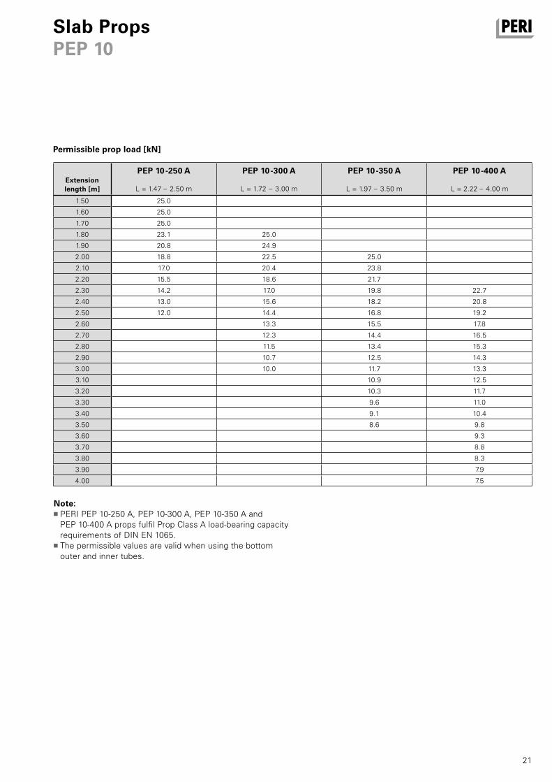
PEP 10-250 A
L = 1.47 – 2.50 m
PEP 10-300 A
L = 1.72 – 3.00 m
PEP 10-350 A
L = 1.97 – 3.50 m
PEP 10-400 A
L = 2.22 – 4.00 m
1.50 25.0
1.60 25.0
1.70 25.0
1.80 23.1 25.0
1.90 20.8 24.9
2.00 18.8 22.5 25.0
2.10 17.0 20.4 23.8
2.20 15.5 18.6 21.7
2.30 14.2 17.0 19.8 22.7
2.40 13.0 15.6 18.2 20.8
2.50 12.0 14.4 16.8 19.2
2.60 13.3 15.5 17.8
2.70 12.3 14.4 16.5
2.80 11.5 13.4 15.3
2.90 10.7 12.5 14.3
3.00 10.0 11.7 13.3
3.10 10.9 12.5
3.20 10.3 11.7
3.30 9.6 11.0
3.40 9.1 10.4
3.50 8.6 9.8
3.60 9.3
3.70 8.8
3.80 8.3
3.90 7.9
4.00 7.5
Slab PropsPEP 10
Permissible prop load [kN]
Extension length [m]
Note:■PERI PEP 10-250 A, PEP 10-300 A, PEP 10-350 A and
PEP 10-400 A props fulfil Prop Class A load-bearing capacity requirements of DIN EN 1065.
■The permissible values are valid when using the bottom outer and inner tubes.
AuV PEP Deckenstutzen Export.indb 21 25.01.16 14:05
22
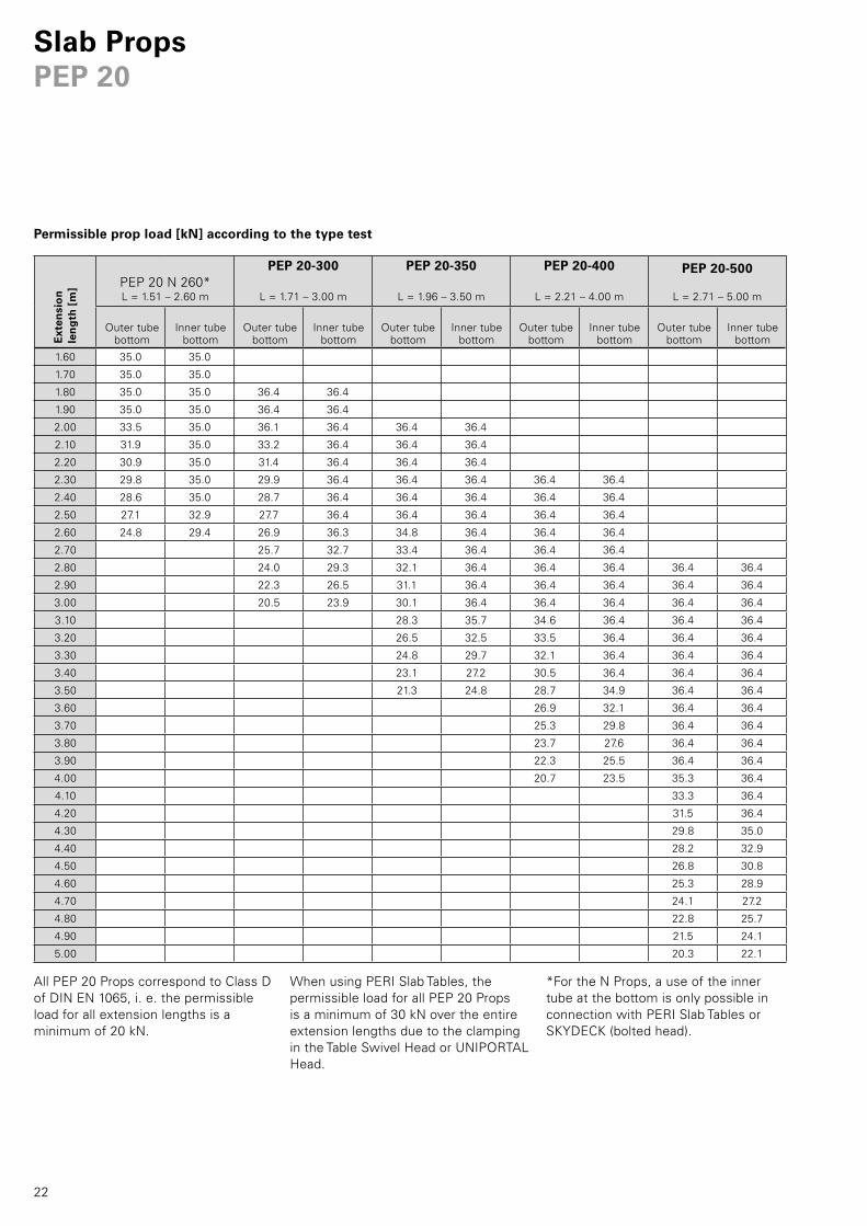
Slab PropsPEP 20
*For the N Props, a use of the inner tube at the bottom is only possible in connection with PERI Slab Tables or SKYDECK (bolted head).
PEP 20 N 260*L = 1.51 – 2.60 m
PEP 20-300
L = 1.71 – 3.00 m
PEP 20-350
L = 1.96 – 3.50 m
PEP 20-400
L = 2.21 – 4.00 m
PEP 20-500
L = 2.71 – 5.00 m
1.60 35.0 35.0
1.70 35.0 35.0
1.80 35.0 35.0 36.4 36.4
1.90 35.0 35.0 36.4 36.4
2.00 33.5 35.0 36.1 36.4 36.4 36.4
2.10 31.9 35.0 33.2 36.4 36.4 36.4
2.20 30.9 35.0 31.4 36.4 36.4 36.4
2.30 29.8 35.0 29.9 36.4 36.4 36.4 36.4 36.4
2.40 28.6 35.0 28.7 36.4 36.4 36.4 36.4 36.4
2.50 27.1 32.9 27.7 36.4 36.4 36.4 36.4 36.4
2.60 24.8 29.4 26.9 36.3 34.8 36.4 36.4 36.4
2.70 25.7 32.7 33.4 36.4 36.4 36.4
2.80 24.0 29.3 32.1 36.4 36.4 36.4 36.4 36.4
2.90 22.3 26.5 31.1 36.4 36.4 36.4 36.4 36.4
3.00 20.5 23.9 30.1 36.4 36.4 36.4 36.4 36.4
3.10 28.3 35.7 34.6 36.4 36.4 36.4
3.20 26.5 32.5 33.5 36.4 36.4 36.4
3.30 24.8 29.7 32.1 36.4 36.4 36.4
3.40 23.1 27.2 30.5 36.4 36.4 36.4
3.50 21.3 24.8 28.7 34.9 36.4 36.4
3.60 26.9 32.1 36.4 36.4
3.70 25.3 29.8 36.4 36.4
3.80 23.7 27.6 36.4 36.4
3.90 22.3 25.5 36.4 36.4
4.00 20.7 23.5 35.3 36.4
4.10 33.3 36.4
4.20 31.5 36.4
4.30 29.8 35.0
4.40 28.2 32.9
4.50 26.8 30.8
4.60 25.3 28.9
4.70 24.1 27.2
4.80 22.8 25.7
4.90 21.5 24.1
5.00 20.3 22.1
Permissible prop load [kN] according to the type test
Ext
ensi
on
len
gth
[m
]
When using PERI Slab Tables, the permissible load for all PEP 20 Props is a minimum of 30 kN over the entire extension lengths due to the clamping in the Table Swivel Head or UNIPORTAL Head.
All PEP 20 Props correspond to Class D of DIN EN 1065, i. e. the permissible load for all extension lengths is a minimum of 20 kN.
Outer tube bottom
Inner tube bottom
Outer tube bottom
Inner tube bottom
Outer tube bottom
Inner tube bottom
Outer tube bottom
Inner tube bottom
Outer tube bottom
Inner tube bottom
AuV PEP Deckenstutzen Export.indb 22 25.01.16 14:05
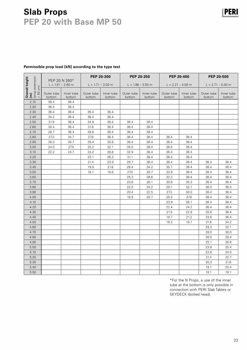
23
PEP 20 N 260*L = 1.51 – 2.60 m
PEP 20-300
L = 1.71 – 3.00 m
PEP 20-350
L = 1.96 – 3.50 m
PEP 20-400
L = 2.21 – 4.00 m
PEP 20-500
L = 2.71 – 5.00 m
2.10 36.4 36.4
2.20 36.4 36.4
2.30 36.4 36.4 36.4 36.4
2.40 34.2 36.4 36.4 36.4
2.50 31.9 36.4 34.9 36.4 36.4 36.4
2.60 30.4 36.4 31.8 36.4 36.4 36.4
2.70 28.7 36.4 29.6 36.4 36.4 36.4
2.80 27.3 34.7 27.8 36.4 36.4 36.4 36.4 36.4
2.90 26.3 30.7 26.4 35.8 36.4 36.4 36.4 36.4
3.00 24.5 27.5 25.2 32.1 35.0 36.4 36.4 36.4
3.10 22.2 24.7 24.2 28.8 32.9 36.4 36.4 36.4
3.20 23.1 26.3 31.1 36.4 36.4 36.4
3.30 21.4 23.9 29.7 36.4 36.4 36.4 36.4 36.4
3.40 19.9 21.8 28.4 34.2 35.7 36.4 36.4 36.4
3.50 18.1 19.8 27.0 30.7 33.9 36.4 36.4 36.4
3.60 25.3 28.6 32.3 36.4 36.4 36.4
3.70 23.6 26.1 30.8 35.3 36.4 36.4
3.80 22.0 24.2 29.1 32.7 36.4 36.4
3.90 20.4 22.5 27.3 30.0 36.4 36.4
4.00 18.9 20.7 25.5 27.8 36.4 36.4
4.10 23.9 26.1 36.4 36.4
4.20 22.4 24.2 36.4 36.4
4.30 21.0 22.8 35.6 36.4
4.40 19.7 21.2 33.6 36.4
4.50 18.3 19.7 31.6 34.2
4.60 29.3 32.1
4.70 28.0 30.0
4.80 26.5 28.4
4.90 25.1 26.8
5.00 23.8 25.4
5.10 22.6 24.0
5.20 21.4 22.7
5.30 20.3 21.6
5.40 19.1 20.4
5.50 18.1 19.1
Slab PropsPEP 20 with Base MP 50
Permissible prop load [kN] according to the type test
Ove
rall
hei
gh
t [m
](p
rop
exte
nsio
n
+ 5
0 cm
)
Outer tube bottom
Inner tube bottom
Outer tube bottom
Inner tube bottom
Outer tube bottom
Inner tube bottom
Outer tube bottom
Inner tube bottom
Outer tube bottom
Inner tube bottom
*For the N Props, a use of the inner tube at the bottom is only possible in connection with PERI Slab Tables or SKYDECK (bolted head).
AuV PEP Deckenstutzen Export.indb 23 25.01.16 14:05
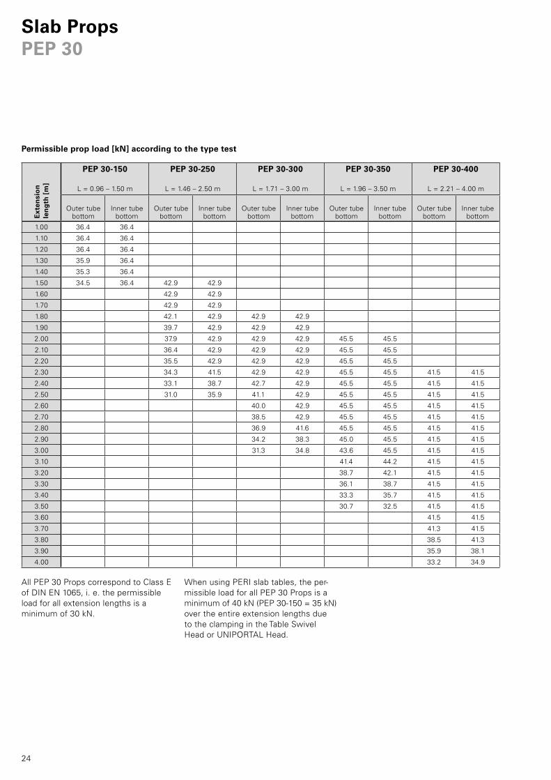
24
PEP 30-150
L = 0.96 – 1.50 m
PEP 30-250
L = 1.46 – 2.50 m
PEP 30-300
L = 1.71 – 3.00 m
PEP 30-350
L = 1.96 – 3.50 m
PEP 30-400
L = 2.21 – 4.00 m
1.00 36.4 36.4
1.10 36.4 36.4
1.20 36.4 36.4
1.30 35.9 36.4
1.40 35.3 36.4
1.50 34.5 36.4 42.9 42.9
1.60 42.9 42.9
1.70 42.9 42.9
1.80 42.1 42.9 42.9 42.9
1.90 39.7 42.9 42.9 42.9
2.00 37.9 42.9 42.9 42.9 45.5 45.5
2.10 36.4 42.9 42.9 42.9 45.5 45.5
2.20 35.5 42.9 42.9 42.9 45.5 45.5
2.30 34.3 41.5 42.9 42.9 45.5 45.5 41.5 41.5
2.40 33.1 38.7 42.7 42.9 45.5 45.5 41.5 41.5
2.50 31.0 35.9 41.1 42.9 45.5 45.5 41.5 41.5
2.60 40.0 42.9 45.5 45.5 41.5 41.5
2.70 38.5 42.9 45.5 45.5 41.5 41.5
2.80 36.9 41.6 45.5 45.5 41.5 41.5
2.90 34.2 38.3 45.0 45.5 41.5 41.5
3.00 31.3 34.8 43.6 45.5 41.5 41.5
3.10 41.4 44.2 41.5 41.5
3.20 38.7 42.1 41.5 41.5
3.30 36.1 38.7 41.5 41.5
3.40 33.3 35.7 41.5 41.5
3.50 30.7 32.5 41.5 41.5
3.60 41.5 41.5
3.70 41.3 41.5
3.80 38.5 41.3
3.90 35.9 38.1
4.00 33.2 34.9
Slab PropsPEP 30
Permissible prop load [kN] according to the type test
Ext
ensi
on
len
gth
[m
]
Outer tube bottom
Inner tube bottom
Outer tube bottom
Inner tube bottom
Outer tube bottom
Inner tube bottom
Outer tube bottom
Inner tube bottom
Outer tube bottom
Inner tube bottom
All PEP 30 Props correspond to Class E of DIN EN 1065, i. e. the permissible load for all extension lengths is a minimum of 30 kN.
When using PERI slab tables, the per-missible load for all PEP 30 Props is a minimum of 40 kN (PEP 30-150 = 35 kN) over the entire extension lengths due to the clamping in the Table Swivel Head or UNIPORTAL Head.
AuV PEP Deckenstutzen Export.indb 24 25.01.16 14:05
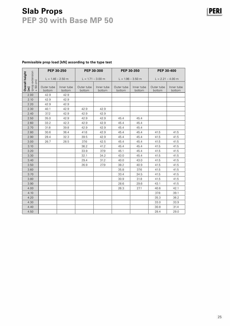
25
PEP 30-250
L = 1.46 – 2.50 m
PEP 30-300
L = 1.71 – 3.00 m
PEP 30-350
L = 1.96 – 3.50 m
PEP 30-400
L = 2.21 – 4.00 m
2.00 42.9 42.9
2.10 42.9 42.9
2.20 42.9 42.9
2.30 40.1 42.9 42.9 42.9
2.40 37.2 42.9 42.9 42.9
2.50 35.0 42.9 42.9 42.9 45.4 45.4
2.60 33.2 42.3 42.9 42.9 45.4 45.4
2.70 31.8 39.8 42.9 42.9 45.4 45.4
2.80 30.6 36.4 41.6 42.9 45.4 45.4 41.5 41.5
2.90 28.4 32.3 39.5 42.9 45.4 45.4 41.5 41.5
3.00 26.7 28.5 37.6 42.5 45.4 45.4 41.5 41.5
3.10 36.2 41.2 45.4 45.4 41.5 41.5
3.20 33.9 37.9 45.1 45.4 41.5 41.5
3.30 32.1 34.2 43.0 45.4 41.5 41.5
3.40 29.4 31.2 40.0 43.0 41.5 41.5
3.50 26.9 27.9 38.2 40.9 41.5 41.5
3.60 35.8 37.6 41.5 41.5
3.70 33.4 34.5 41.5 41.5
3.80 30.9 31.8 41.5 41.5
3.90 28.6 29.6 43.1 41.5
4.00 26.3 27.1 40.6 42.1
4.10 37.8 39.1
4.20 35.3 36.2
4.30 33.0 33.9
4.40 30.8 31.4
4.50 28.4 29.0
Slab PropsPEP 30 with Base MP 50
Permissible prop load [kN] according to the type test
Outer tube bottom
Inner tube bottom
Outer tube bottom
Inner tube bottom
Outer tube bottom
Inner tube bottom
Outer tube bottom
Inner tube bottomO
vera
ll h
eig
ht
[m]
(pro
p ex
tens
ion
+
50
cm)
AuV PEP Deckenstutzen Export.indb 25 25.01.16 14:05
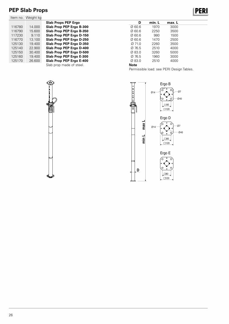
PEP Slab Props
26
Item no. Weight kg
116780116790117230116770125130125140125150125160125170
14.000 15.600 9.110 13.100 19.400 22.900 30.400 19.400 26.600
Slab Props PEP ErgoSlab Prop PEP Ergo B-300Slab Prop PEP Ergo B-350Slab Prop PEP Ergo D-150Slab Prop PEP Ergo D-250Slab Prop PEP Ergo D-350Slab Prop PEP Ergo D-400Slab Prop PEP Ergo D-500Slab Prop PEP Ergo E-300Slab Prop PEP Ergo E-400Slab prop made of steel.
D min. L max. L Ø 60.6 1970 3000 Ø 60.6 2250 3500 Ø 60.6 980 1500 Ø 60.6 1470 2500 Ø 71.0 2260 3500 Ø 76.5 2510 4000 Ø 83.0 3260 5000 Ø 76.5 1960 3000 Ø 83.0 2510 4000 NotePermissible load: see PERI Design Tables.
min
Lm
axL
Ø7
Ergo B
Ergo D
Ergo E
D
Ø40
Ø14
80 120
120 80
12080
Ø7
Ø40
Ø14
AuV PEP Deckenstutzen Export.indb 26 25.01.16 14:05
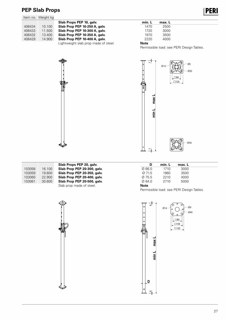
PEP Slab Props
27
Item no. Weight kg
103058103059103060103061
16.100 19.600 22.900 30.600
Slab Props PEP 20, galv.Slab Prop PEP 20-300, galv.Slab Prop PEP 20-350, galv.Slab Prop PEP 20-400, galv.Slab Prop PEP 20-500, galv.Slab prop made of steel.
D min. L max. L Ø 66.0 1710 3000 Ø 71.5 1960 3500 Ø 75.5 2210 4000 Ø 84.0 2710 5000 NotePermissible load: see PERI Design Tables.
66
min
Lm
axL
Ø40
Ø9Ø14
80100120
D
406434406433406432406429
10.100 11.500 13.400 14.900
Slab Props PEP 10, galv.Slab Prop PEP 10-250 A, galv.Slab Prop PEP 10-300 A, galv.Slab Prop PEP 10-350 A, galv.Slab Prop PEP 10-400 A, galv.Lightweight slab prop made of steel.
min. L max. L 1470 2500 1720 3000 1970 3500 2220 4000 NotePermissible load: see PERI Design Tables.
7m
inL
max
L7
80120
Ø30
Ø5Ø14
Ø40
AuV PEP Deckenstutzen Export.indb 27 25.01.16 14:05
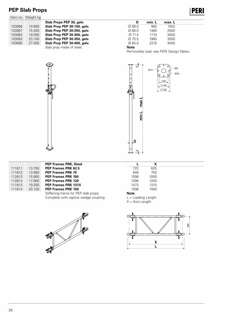
PEP Slab Props
28
Item no. Weight kg
111811111812112813112814111813111814
13.700 13.900 15.900 17.800 19.200 20.100
PEP Frames PRK, SteelPEP Frames PRK 62.5PEP Frames PRK 75PEP Frames PRK 100PEP Frames PRK 120PEP Frames PRK 137.5PEP Frames PRK 150Stiffening frame for PEP slab props. Complete with captive wedge coupling.
L X 723 625 848 750 1098 1000 1298 1200 1473 1375 1598 1500 NoteL = Loading Length X = Axis Length
XL
500
103066103067103062103063103065
10.800 15.400 19.000 23.100 27.500
Slab Props PEP 30, galv.Slab Prop PEP 30-150, galv.Slab Prop PEP 30-250, galv.Slab Prop PEP 30-300, galv.Slab Prop PEP 30-350, galv.Slab Prop PEP 30-400, galv.Slab prop made of steel.
D min. L max. L Ø 66.0 960 1500 Ø 66.0 1460 2500 Ø 71.5 1710 3000 Ø 75.5 1960 3500 Ø 84.0 2210 4000 NotePermissible load: see PERI Design Tables.
88
min
Lm
axL
Ø40
Ø9Ø14
80 100 120
D
AuV PEP Deckenstutzen Export.indb 28 25.01.16 14:05
PEP Slab Props
29
Item no. Weight kg
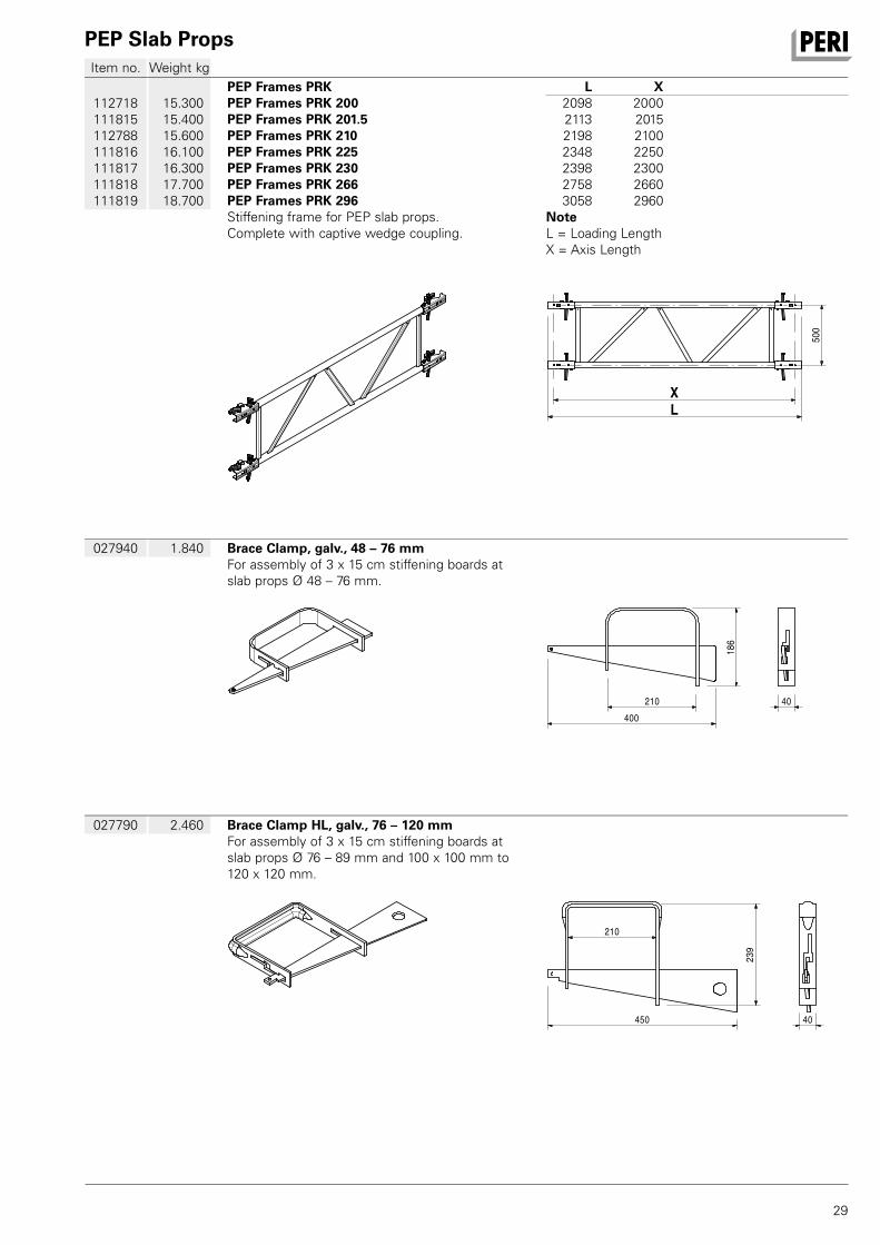
027790 2.460 Brace Clamp HL, galv., 76 – 120 mmFor assembly of 3 x 15 cm stiffening boards at slab props Ø 76 – 89 mm and 100 x 100 mm to 120 x 120 mm.
210
239
40450
027940 1.840 Brace Clamp, galv., 48 – 76 mmFor assembly of 3 x 15 cm stiffening boards at slab props Ø 48 – 76 mm.
210400
186
40
112718111815112788111816111817111818111819
15.300 15.400 15.600 16.100 16.300 17.700 18.700
PEP Frames PRKPEP Frames PRK 200PEP Frames PRK 201.5PEP Frames PRK 210PEP Frames PRK 225PEP Frames PRK 230PEP Frames PRK 266PEP Frames PRK 296Stiffening frame for PEP slab props. Complete with captive wedge coupling.
L X 2098 2000 2113 2015 2198 2100 2348 2250 2398 2300 2758 2660 3058 2960 NoteL = Loading Length X = Axis Length
LX
500
AuV PEP Deckenstutzen Export.indb 29 25.01.16 14:05
PEP Slab Props
30
Item no. Weight kg
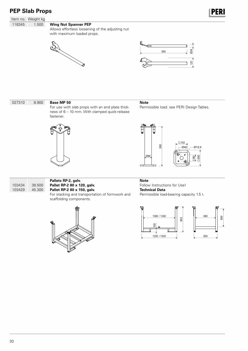
103434103429
38.500 45.300
Pallets RP-2, galv.Pallet RP-2 80 x 120, galv.Pallet RP-2 80 x 150, galv.For stacking and transportation of formwork and scaffolding components.
NoteFollow Instructions for Use!Technical DataPermissible load-bearing capacity 1.5 t.
1200 / 1500
1080 / 1380
853 60
0
100
800
680
027310 8.900 Base MP 50For use with slab props with an end plate thick-ness of 6 – 10 mm. With clamped quick-release fastener.
NotePermissible load: see PERI Design Tables.
500
89Ø
200
150
80
Ø12,5Ø42
118345 1.500 Wing Nut Spanner PEPAllows effortless loosening of the adjusting nut with maximum loaded props.
34Ø595
121
AuV PEP Deckenstutzen Export.indb 30 25.01.16 14:05
PEP Slab Props
31
Item no. Weight kg
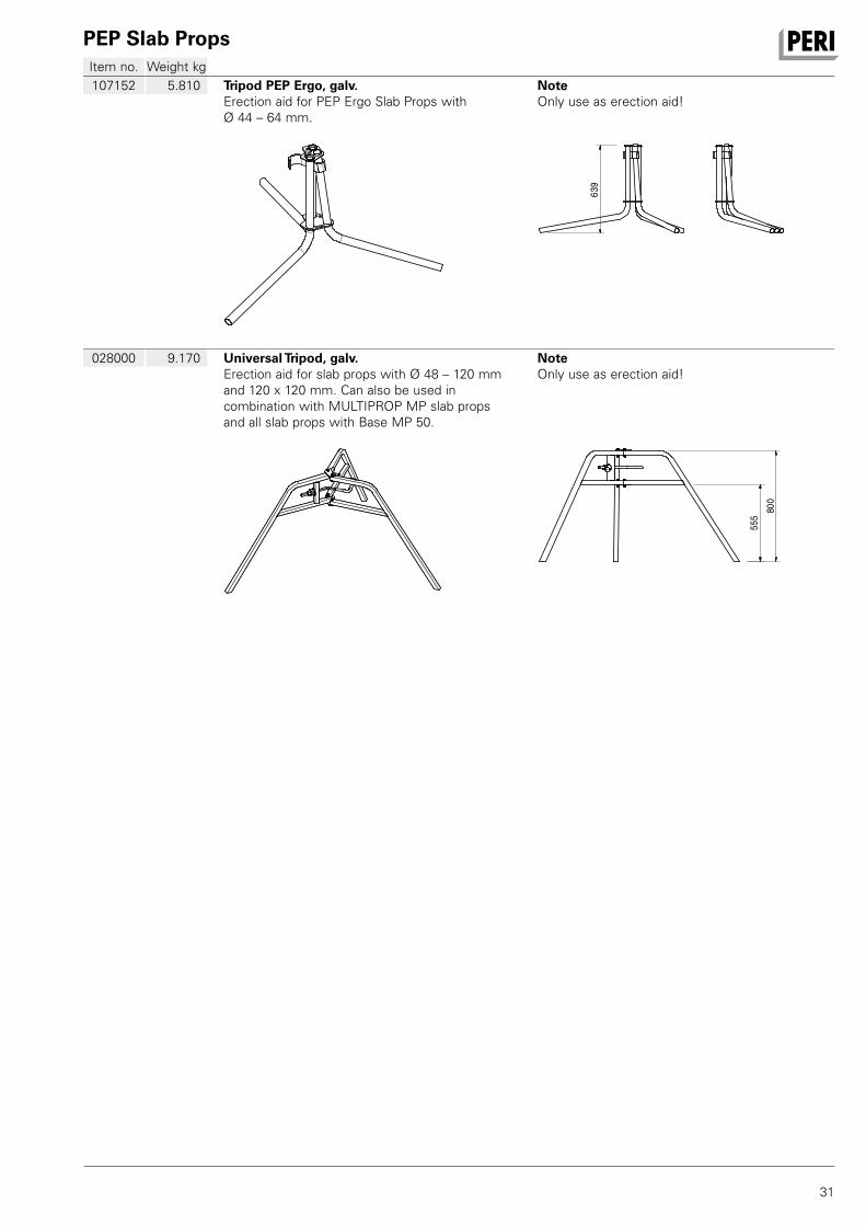
028000 9.170 Universal Tripod, galv.Erection aid for slab props with Ø 48 – 120 mm and 120 x 120 mm. Can also be used in combination with MULTIPROP MP slab props and all slab props with Base MP 50.
NoteOnly use as erection aid!
555
800
107152 5.810 Tripod PEP Ergo, galv.Erection aid for PEP Ergo Slab Props with Ø 44 – 64 mm.
NoteOnly use as erection aid!
639
AuV PEP Deckenstutzen Export.indb 31 25.01.16 14:05

32
PERI_Deutschland.indd 32 25.01.16 14:09

33
PERI_Deutschland.indd 33 25.01.16 14:09
2
1
3
4
5
6
9
11
12
1316
17
18
19
20
22
21
24
2829
30
32
33
34
38
41
42
46
48
52
44
53
60
34
02 PERI S.A.S. 77109 Meaux Cedex [email protected] www.peri.fr
03 PERI AG 8472 Ohringen [email protected] www.peri.ch
04 PERI S.A.U. 28110 Algete - Madrid [email protected] www.peri.es
05 N.V. PERI S.A. 1840 Londerzeel [email protected] www.peri.be
06 PERI Holding B.V. 5480 AH-Schijndel [email protected] www.peri.nl
07 PERI Formwork Systems, Inc. Elkridge, MD 21075 [email protected] www.peri-usa.com
08 PT Beton Perkasa Wijaksana Jakarta 10210 [email protected] www.peri.com
09 PERI S.p.A. 20060 Basiano [email protected] www.peri.it
10 PERI Japan K.K. Tokyo 103-0015 [email protected] www.perijapan.jp
11 PERI Ltd. Rugby, CV23 0AN [email protected] www.peri.ltd.uk
12 PERI Kalip ve Iskeleleri Sanayi ve Ticaret Ltd. Esenyurt / İstanbul 34510 [email protected] www.peri.com.tr
13 PERI Kft. 1181 Budapest [email protected] www.peri.hu
14 PERI Formwork Malaysia Sdn. Bhd. 43300 Seri Kembangan, Selangor Darul Ehsan [email protected] www.perimalaysia.com
15 PERI Asia Pte Ltd Singapore 387355 [email protected] www.periasia.com
16 PERI Ges.mbH 3134 Nußdorf ob der Traisen [email protected] www.peri.at
17 PERI spol. S r.o. 252 42 Jesenice u Prahy [email protected] www.peri.cz
18 PERI Danmark A/S 2670 Greve [email protected] www.peri.dk
19 PERI Suomi Ltd. Oy 05460 Hyvinkää [email protected] www.perisuomi.fi
20 PERI Norge AS 3036 Drammen [email protected] www.peri.no
21 PERI Polska Sp. z o.o. 05-860 Płochocin [email protected] www.peri.com.pl
22 PERI Sverige AB 30262 Halmstad [email protected] www.periform.se
23 PERI (Korea) Ltd. Seoul 06243 [email protected] www.perikorea.com
24 Pericofragens Lda. 2790-326 Queijas [email protected] www.peri.pt
25 PERI S.A. B1625GPA Escobar – Bs. As. [email protected] www.peri.com.ar
26 PERI Formas e Escoramentos Ltda. Vargem Grande Paulista – SP [email protected] www.peribrasil.com.br
27 PERI Chile Ltda. Colina, Santiago de Chile [email protected] www.peri.cl
28 PERI România SRL 077015 Baloteşti [email protected] www.peri.ro
29 PERI Agency 2000 Maribor [email protected] www.peri.com
30 PERI spol. s. r.o. 903 01 Senec [email protected] www.peri.sk
31 PERI Australia Pty. Ltd. Glendenning NSW 2761 [email protected] www.periaus.com.au
32 PERI AS 76406 Saku vald Harjumaa [email protected] www.peri.ee
33 PERI Hellas Solely Owned Ltd. 194 00 Koropi [email protected] www.perihellas.gr
34 PERI SIA 2118 Salaspils novads, Rigas rajons [email protected] www.peri-latvija.lv
35 PERI (L.L.C.) Dubai U.A.E. [email protected] www.perime.com
36 PERI Formwork Systems, Inc. Bolton, ON – L7E 1K1 [email protected] www.peri.ca
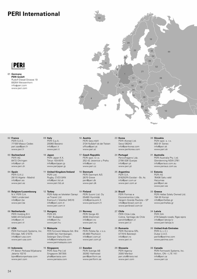
01 Germany PERI GmbH Rudolf-Diesel-Strasse 19 89264 Weissenhorn [email protected] www.peri.com
France
Switzerland
Spain
Belgium/Luxembourg
Netherlands
USA
Indonesia
Italy
Japan
United Kingdom/Ireland
Turkey
Hungary
Malaysia
Singapore
Austria
Czech Republic
Denmark
Finland
Norway
Poland
Sweden
Korea
Portugal
Argentina
Brazil
Chile
Romania
Slovania
Slovakia
Australia
Estonia
Greece
Latvia
United Arab Emirates
Canada
PERI International
PERI_International_2015.indd 34 25.01.16 14:10
8
10
1415
23
67
68
31
35
3739 40
43
44
45
47
50 51
5854
70
69
57
5659 55
64
63
65
7
25
26
66
27
36
49
61
62
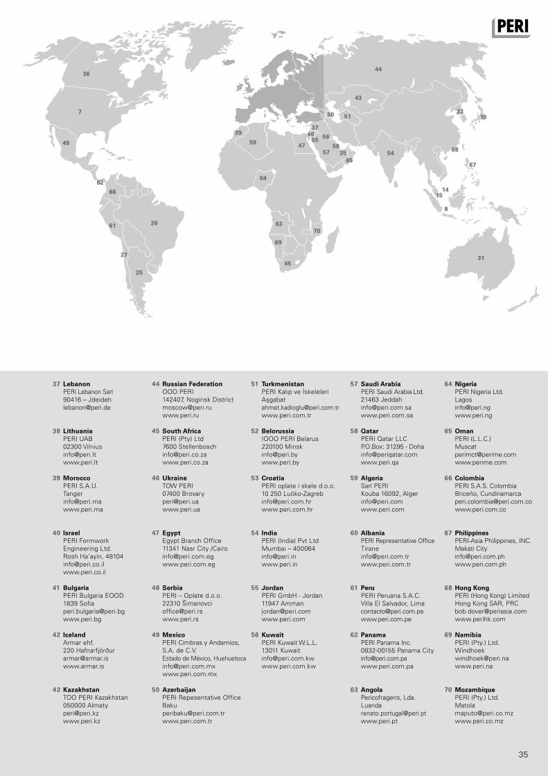
35
37 PERI Lebanon Sarl 90416 – Jdeideh [email protected]
38 PERI UAB 02300 Vilnius [email protected] www.peri.lt
39 PERI S.A.U. Tanger [email protected] www.peri.ma
40 PERI Formwork Engineering Ltd. Rosh Ha‘ayin, 48104 [email protected] www.peri.co.il
41 PERI Bulgaria EOOD 1839 Sofia [email protected] www.peri.bg
42 Armar ehf. 220 Hafnarfjörður [email protected] www.armar.is
43 TOO PERI Kazakhstan 050000 Almaty [email protected] www.peri.kz
44 OOO PERI 142407, Noginsk District [email protected] www.peri.ru
45 PERI (Pty) Ltd 7600 Stellenbosch [email protected] www.peri.co.za
46 TOW PERI 07400 Brovary [email protected] www.peri.ua
47 Egypt Branch Office 11341 Nasr City /Cairo [email protected] www.peri.com.eg
48 PERI – Oplate d.o.o. 22310 Šimanovci [email protected] www.peri.rs
49 PERI Cimbras y Andamios, S.A. de C.V. Estado de México, Huehuetoca [email protected] www.peri.com.mx
50 PERI Repesentative Office Baku [email protected] www.peri.com.tr
51 PERI Kalıp ve İskeleleri Aşgabat [email protected] www.peri.com.tr
52 IOOO PERI Belarus 220100 Minsk [email protected] www.peri.by
53 PERI oplate i skele d.o.o. 10 250 Luöko-Zagreb [email protected] www.peri.com.hr
54 PERI (India) Pvt Ltd Mumbai – 400064 [email protected] www.peri.in
55 PERI GmbH - Jordan 11947 Amman [email protected] www.peri.com
56 PERI Kuwait W.L.L. 13011 Kuwait [email protected] www.peri.com.kw
57 PERI Saudi Arabia Ltd. 21463 Jeddah [email protected] www.peri.com.sa
58 PERI Qatar LLC P.O.Box: 31295 - Doha [email protected] www.peri.qa
59 Sarl PERI Kouba 16092, Alger [email protected] www.peri.com
60 PERI Representative Office Tirane [email protected] www.peri.com.tr
61 PERI Peruana S.A.C. Villa El Salvador, Lima [email protected] www.peri.com.pe
62 PERI Panama Inc. 0832-00155 Panama City [email protected] www.peri.com.pa
63 Pericofragens, Lda. Luanda [email protected] www.peri.pt
64 PERI Nigeria Ltd. Lagos [email protected] www.peri.ng 65 PERI (L.L.C.) Muscat [email protected] www.perime.com
66 PERI S.A.S. Colombia Briceño, Cundinamarca [email protected] www.peri.com.co
67 PERI-Asia Philippines, INC. Makati City [email protected] www.peri.com.ph
68 PERI (Hong Kong) Limited Hong Kong SAR, PRC [email protected] www.perihk.com
69 PERI (Pty.) Ltd. Windhoek [email protected] www.peri.na
70 PERI (Pty.) Ltd. Matola [email protected] www.peri.co.mz
Lebanon
Lithuania
Morocco
Israel
Bulgaria
Iceland
Kazakhstan
Russian Federation
South Africa
Ukraine
Egypt
Serbia
Mexico
Azerbaijan
Turkmenistan
Belorussia
Croatia
India
Jordan
Kuwait
Saudi Arabia
Qatar
Algeria
Albania
Peru
Panama
Angola
Nigeria
Oman
Colombia
Philippines
Hong Kong
Namibia
Mozambique
PERI_International_2015.indd 35 25.01.16 14:10

DE
en 0
1 | 2
016
3sm
793
295
© P
ER
I Gm
bH
The optimal System for every Project and every Requirement
PERI GmbHFormwork Scaffolding EngineeringRudolf-Diesel-Strasse 1989264 WeissenhornGermanyTel. +49 (0)7309.950-0Fax +49 (0)[email protected]
System-Independent Accessories
Wall Formwork Column Formwork
Slab Formwork Climbing Systems Tunnel Formwork Bridge Formwork
Shoring Systems Facade ScaffoldConstruction Scaffold Industrial Scaffold
Access Protection Scaffold Services
EN_Ruecks_SW2011.indd 92 25.01.16 14:07