MRI Chiller Installation Guidelines - Dimplex Thermal Solutions · 2018-09-27 · refer to chiller...
24
Form R‐M005.2 Rev. 1: Rev. Date 7/1/2016 Author/Revs: KB, AS, KH MRI Chiller Installation Guidelines *These Items are the responsibility of the installing contractor to complete prior to the startup of the MRI Chiller.* **Please refer to DTS chiller manual for further info. Contact DTS at 800‐968‐5665 for questions or concerns with these items** Setting and Rigging: Chiller Weights: Arrangements: REFER TO CHILLER CUTSHEETS OR DRAWINGS THAT ARE INCLUDED IN THIS PACKET FOR THESE SPECS. ENSURE YOU MATCH YOUR CHILLER MODEL TO THE DRAWING YOU ARE LOOKING AT BEFORE SIZING CRANES, PADS, CURBS, ETC. Unit and accessories will arrive on a flat‐bed truck. The freight carrier does not provide unloading service. Include any necessary rigging fees in your installation bid. Ground Level Setting: Place unit on a concrete pad. Standard dimensions: 5’W x 12’L x min 4” depth. *Ensure you size your pad based on the chiller you are receiving* Pad must be poured with less than ½” slope per 10’ or be shimmed to level. Ensure placement is minimum 5 feet (6 feet recommended) from walls and minimum 8 feet overhead clearance. Secure unit to pad with 1/2” bolts at all 8 feet. Roof Level Setting: Always follow all local ordinances and codes for roof installations. If OSHPD certification is required in your area, please ensure you are installing an OSHPD certified chiller. Chillers are capable of pumping 65 feet vertical distance to MRI SEP cabinet. Please reach out to DTS prior to installation if your site planning exceeds this limit. For rooftop installs where the unit is above patient rooms or staff areas, DTS recommends the use of Isolation springs that are placed between the chiller and roof curb to eliminate vibration. DTS does not provide roof curbs, installation contractor must include these if needed.
Transcript of MRI Chiller Installation Guidelines - Dimplex Thermal Solutions · 2018-09-27 · refer to chiller...

Form R‐M005.2 Rev. 1: Rev. Date 7/1/2016 Author/Revs: KB, AS, KH
MRIChillerInstallationGuidelines*These Items are the responsibility of the installing contractor to complete prior to the startup of the MRI Chiller.*
**Please refer to DTS chiller manual for further info. Contact DTS at 800‐968‐5665 for questions or concerns with these items** SettingandRigging:
Chiller Weights:
Arrangements:
REFER TO CHILLER CUTSHEETS OR DRAWINGS THAT ARE INCLUDED IN THIS PACKET FOR THESE SPECS. ENSURE YOU MATCH YOUR CHILLER MODEL TO THE DRAWING YOU ARE LOOKING AT BEFORE SIZING CRANES, PADS, CURBS, ETC.
Unit and accessories will arrive on a flat‐bed truck. The freight carrier does not provide unloading service. Include any necessary rigging fees in your installation bid.
Ground Level Setting:
Place unit on a concrete pad. Standard dimensions: 5’W x 12’L x min 4” depth. *Ensure you size your pad based on the chiller you are receiving* Pad must be poured with less than ½” slope per 10’ or be shimmed to level. Ensure placement is minimum 5 feet (6 feet recommended) from walls and minimum 8 feet overhead clearance. Secure unit to pad with 1/2” bolts at all 8 feet.
Roof Level Setting: Always follow all local ordinances and codes for roof installations. If OSHPD certification is required in your area, please ensure you are installing an OSHPD certified chiller. Chillers are capable of pumping 65 feet vertical distance to MRI SEP cabinet. Please reach out to DTS prior to installation if your site planning
exceeds this limit. For rooftop installs where the unit is above patient rooms or staff areas, DTS recommends the use of Isolation springs that are placed between
the chiller and roof curb to eliminate vibration. DTS does not provide roof curbs, installation contractor must include these if needed.

Form R‐M005.2 Rev. 1: Rev. Date 7/1/2016 Author/Revs: KB, AS, KH
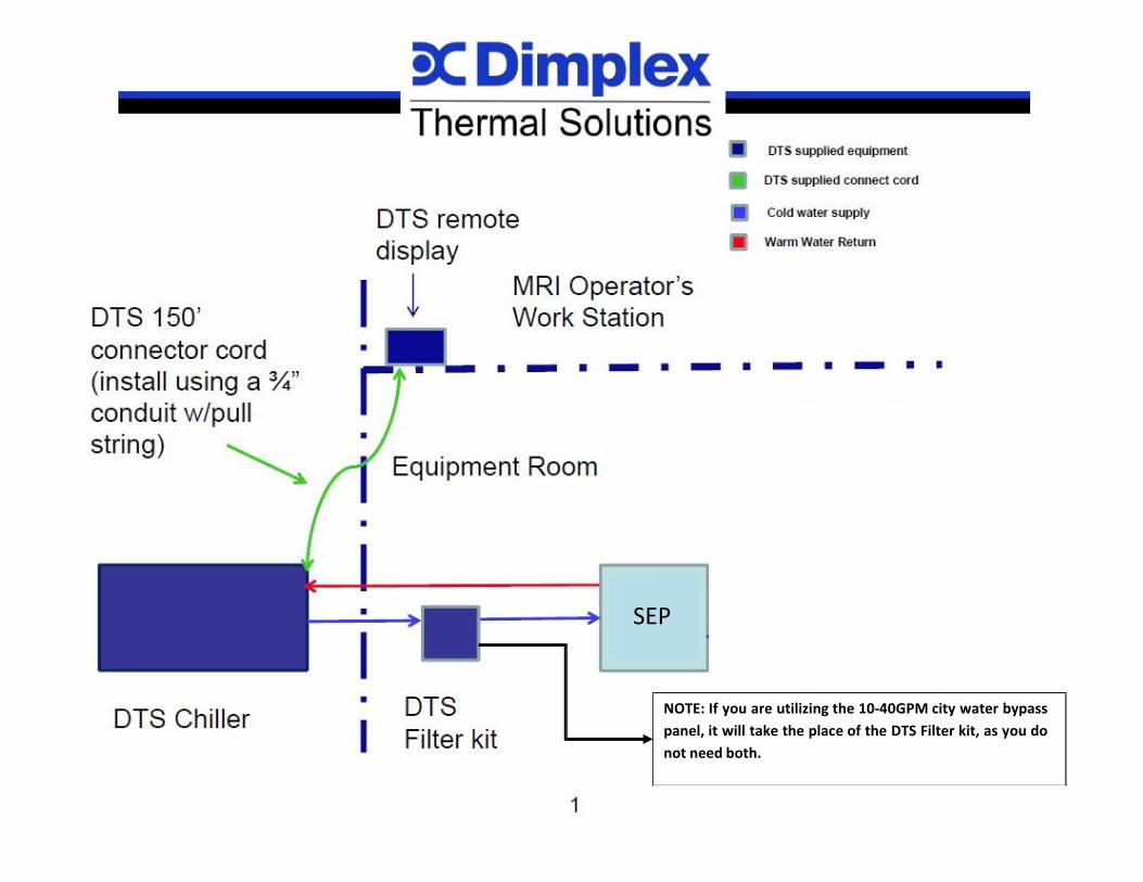
Plumbing: Provide fluid piping – Please refer to document MED‐WI‐010 for further instruction Copper is recommended with flex connectors and isolation ball valves at the chiller inlet and outlet connections. Chiller inlet and outlet ports are referenced on the cutsheet of the applicable chiller you are installing. Refer to these documents as needed. 45, 60, 63, 70, and 106kW chillers can support a maximum total of 500 equivalent feet of piping. (supply pipe ft. + return pipe ft. + total fittings ft.) If your run
exceeds this, please reach out to DTS for information and recommendations. If your chiller is not one of the mentioned, please reach out to DTS. Each chiller is supplied with a filter flow meter kit to be installed indoors on the supply line from the chiller to the SEP. Refer to the Filter Flow Meter
Kit manual for information. ProcessFluid:
Fill chiller and pipes with glycol mixture – Please refer to document MED‐WI‐011 for further instruction Glycol can be purchased from DTS, or sourced by the group installing the chiller. DTS recommends a 50% mix of inhibited propylene glycol to water. Installation contractor must provide distilled or DI water to mix with glycol (if not using pre‐mixed glycol). 45‐65+ gallons will be needed. TAP WATER IS NOT APPROVED TO MIX WITH GLYCOL. The naturally occurring minerals and sediments in tap water will cause the fluid to fall outside the
water purity specification required by MRI equipment. Dilute the glycol to a 50/50 glycol‐water mixture with the water provided. Fill the system with the mixture
o Fill the chiller reservoir first. The capacity of the reservoir by model can be found in the cutsheet for the chiller you are installing. This can be filled through the sight glass or the fill cap on top of the chiller reservoir.
o 1 gallon per 6’ of 2” piping will be required to fill the plumbing lines. o You cannot fill the chiller through the pipes. There are anti‐backflow solenoids that prevent that. It must be filled direct into the chiller.
Electrical:
Provide electrical supply to chiller – Please refer to document MED‐WI‐012 for further instruction Refer to the data tag on the chiller for electrical information. Refer to the above referenced document for further power requirements Connect power drop, turn chiller disconnect to “ON” and check for proper phasing. Correct phasing if needed. Leave on until chiller startup. A Carel remote display panel with 150’ connector cord is included with each shipment. These pieces are located within the electrical enclosure of the
chiller. If the distance of the chiller from where the remote display panel will be installed exceeds 150’, you must purchase the Long Distance Remote Kit. This
will increase the acceptable distance from 150’ up to 400’.
Form R‐M005.2 Rev. 1: Rev. Date 7/1/2016 Author/Revs: KB, AS, KH
SEP
NOTE: If you are utilizing the 10‐40GPM city water bypass panel, it will take the place of the DTS Filter kit, as you do not need both.

DEPT. MANAGER: K. HASTINGS INITIAL ISSUE DATE: 7/1/2016
SUBJECT: W Series Installation Guidelines ‐ Plumbing
NUMBER: MED‐WI‐010
REV ISSUE DATE: 1/9/2017 REV: 02 PAGE 1 OF 6
Purpose: Define process of W Series chiller plumbing connections and installations
Scope: Applicable to all field personnel participating in installation of defined equipment.
Related Documents:
F‐M001, MED‐WI‐011
Affected Equipment:
WVO3000 WO5000 (12kW) WO7500 (17kW/21kW) WO2‐7500 (37kW) WO2‐2‐5000 (60/63kW) WO2‐2‐7500 (70kW) WO2‐10000 (45kW) WO2‐2‐10000 (75kW) WO3‐2‐10000(106kW)
Process:
1. Verify chiller model via datatag located on chiller E‐Box and that the model aligns as a piece of Affected Equipment within this document.
2. Utilize this document and chiller manual provided to determine that site pipe run is acceptable by DTS requirements. If the provided document does not provide adequate verification, call Dimplex Thermal Solutions’ Medical Service team at 800‐968‐5665 x710.
3. Refer to recommended piping layout on page 5 of this document. 4. Follow plumbing related guidelines listed in Chiller Installation Responsibility Checklist
(F‐M001). 5. Complete plumbing connections 6. Leak check piping installation. Ensure chiller is isolated from site piping before putting
plumbing under any pressure. 7. Flush piping to remove any installation debris 8. Back fill chiller lines with glycol mixture (process for this defined in MED‐WI‐011) if
applicable. 9. Wait for chiller startup to be completed to verify no plumbing issues exist
DEPT. MANAGER: K. HASTINGS INITIAL ISSUE DATE: 7/1/2016
SUBJECT: W Series Installation Guidelines ‐ Plumbing
NUMBER: MED‐WI‐010
REV ISSUE DATE: 1/9/2017 REV: 02 PAGE 2 OF 6 Plumbing Recommendations:
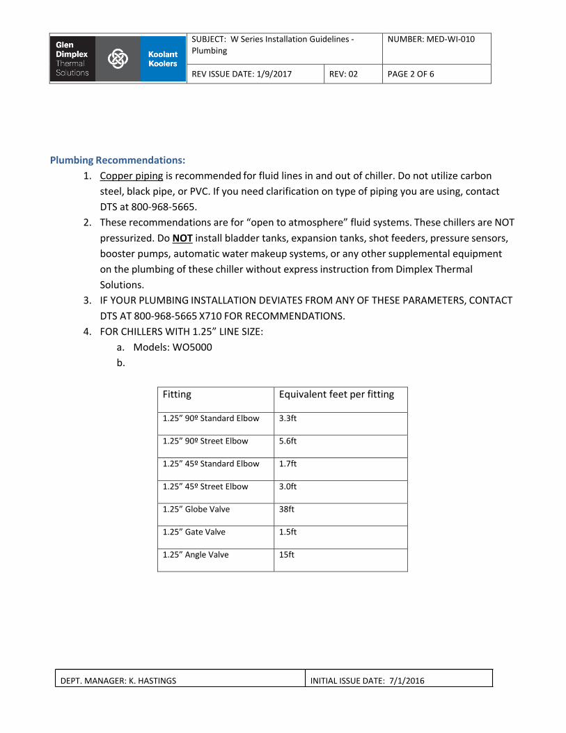
1. Copper piping is recommended for fluid lines in and out of chiller. Do not utilize carbon steel, black pipe, or PVC. If you need clarification on type of piping you are using, contact DTS at 800‐968‐5665.
2. These recommendations are for “open to atmosphere” fluid systems. These chillers are NOT pressurized. Do NOT install bladder tanks, expansion tanks, shot feeders, pressure sensors, booster pumps, automatic water makeup systems, or any other supplemental equipment on the plumbing of these chiller without express instruction from Dimplex Thermal Solutions.
3. IF YOUR PLUMBING INSTALLATION DEVIATES FROM ANY OF THESE PARAMETERS, CONTACT DTS AT 800‐968‐5665 X710 FOR RECOMMENDATIONS.
4. FOR CHILLERS WITH 1.25” LINE SIZE: a. Models: WO5000 b.
Fitting Equivalent feet per fitting
1.25” 90º Standard Elbow 3.3ft
1.25” 90º Street Elbow 5.6ft
1.25” 45º Standard Elbow 1.7ft
1.25” 45º Street Elbow 3.0ft
1.25” Globe Valve 38ft
1.25” Gate Valve 1.5ft
1.25” Angle Valve 15ft
DEPT. MANAGER: K. HASTINGS INITIAL ISSUE DATE: 7/1/2016
SUBJECT: W Series Installation Guidelines ‐ Plumbing
NUMBER: MED‐WI‐010
REV ISSUE DATE: 1/9/2017 REV: 02 PAGE 3 OF 6
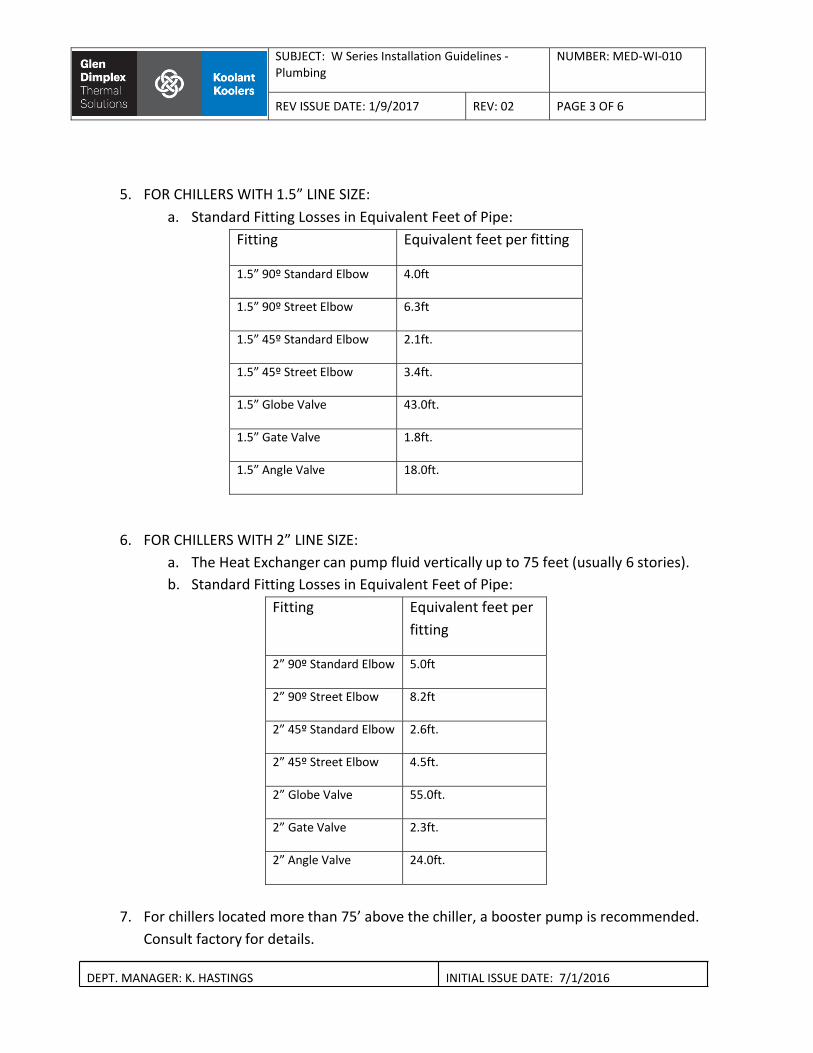
5. FOR CHILLERS WITH 1.5” LINE SIZE: a. Standard Fitting Losses in Equivalent Feet of Pipe:
Fitting Equivalent feet per fitting
1.5” 90º Standard Elbow 4.0ft
1.5” 90º Street Elbow 6.3ft
1.5” 45º Standard Elbow 2.1ft.
1.5” 45º Street Elbow 3.4ft.
1.5” Globe Valve 43.0ft.
1.5” Gate Valve 1.8ft.
1.5” Angle Valve 18.0ft.
6. FOR CHILLERS WITH 2” LINE SIZE: a. The Heat Exchanger can pump fluid vertically up to 75 feet (usually 6 stories). b. Standard Fitting Losses in Equivalent Feet of Pipe:
Fitting Equivalent feet per fitting
2” 90º Standard Elbow 5.0ft
2” 90º Street Elbow 8.2ft
2” 45º Standard Elbow 2.6ft.
2” 45º Street Elbow 4.5ft.
2” Globe Valve 55.0ft.
2” Gate Valve 2.3ft.
2” Angle Valve 24.0ft.
7. For chillers located more than 75’ above the chiller, a booster pump is recommended.
Consult factory for details.
DEPT. MANAGER: K. HASTINGS INITIAL ISSUE DATE: 7/1/2016
SUBJECT: W Series Installation Guidelines ‐ Plumbing
NUMBER: MED‐WI‐010
REV ISSUE DATE: 1/9/2017 REV: 02 PAGE 4 OF 6
8. FOR CHILLERS WITH ANY LINE SIZE NOT DEFINED IN THIS DOCUMENT a. If you have a chiller with a different line size then defined in this document, please
call DTS at 800‐968‐5665 x710 for clarification b. Please note that the chillers listed in this document are for builds that are open to
the atmosphere. These guidelines do NOT apply to pressurized chiller

SUBJECT: W Series Installation Guidelines ‐Plumbing
NUMBER: MED‐WI‐010
REV ISSUE DATE: 1/9/2017 REV: 02 PAGE 5 OF 6
DEPT. MANAGER: K. HASTINGS INITIAL ISSUE DATE: 7/1/2016
Revision History

DEPT. MANAGER: K. HASTINGS INITIAL ISSUE DATE: 7/1/2016
SUBJECT: W Series Installation Guidelines ‐ Plumbing
NUMBER: MED‐WI‐010
REV ISSUE DATE: 1/9/2017 REV: 02 PAGE 6 OF 6
Version Revision Date Description of Change Changes Made By (Name & Title):001 7/1/2016 Creation of document Kyle Hastings, Medical Service Manager002 1/9/2017 Edit Process step 6, general grammar updates Kyle Hastings, Medical Service Manager

DEPT. MANAGER: K. HASTINGS INITIAL ISSUE DATE: 7/1/2016
SUBJECT: W Series Installation Guidelines – Process Fluid
NUMBER: MED‐WI‐011
REV ISSUE DATE: 1/9/2017 REV: 02 PAGE 1 OF 4
Purpose: Define process of W Series chiller process fluid installation and fill.
Scope: Applicable to all field personnel participating in installation of defined equipment.
Related Documents:
F‐M001, MED‐WI‐010
Affected Equipment:
WVO3000 WO5000 (12kW) WO7500 (17kW/21kW) WO2‐7500 (37kW) WO2‐2‐5000 (60/63kW) WO2‐2‐7500 (70kW) WO2‐10000 (45kW) WO2‐2‐10000 (75kW) WO3‐2‐10000(106kW)
Process: 1. Complete rigging and setting of chiller at end user location. 2. Ensure site plumbing has been flushed clean and has no residual installation debris. DO NOT
FLUSH PLUMBING THROUGH CHILLER OR PROCESS EQUIPMENT AS DAMAGE MAY RESULT. 3. Utilize this document and chiller manual to determine volume of fluid mixture needed for
system. 4. If needed, source glycol and water for mixture. 5. Add correct fluid mixture to chiller reservoir.
i. Remove air filters from chiller. ii. Remove vent cap or stainless steel plate that is on top of the reservoir. iii. Pump directly into the tank until the appropriate mixture is reached and the fluid
level sight glass on the chiller is at the MAX level. iv. Reinstall reservoir cap once system is full and free of air. v. Reinstall chiller air filters.
6. If plumbing system has fill ports or other ways to backfill the piping, add the same concentration of fluid mixture used in the reservoir to fill the pipe lines.
7. Wait for startup of chiller to verify correct concentration and fluid level is achieved with system fully operational.

DEPT. MANAGER: K. HASTINGS INITIAL ISSUE DATE: 7/1/2016
SUBJECT: W Series Installation Guidelines – Process Fluid
NUMBER: MED‐WI‐011
REV ISSUE DATE: 1/9/2017 REV: 02 PAGE 2 OF 4
8. Make any corrections necessary.
Process Fluid Recommendations:
1. Reservoir Capacity by model:
Chiller Model Reservoir Capacity (US Gallons)
WVO3000 10
WO5000 50
WO7500 50
WO2‐7500 70
WO2‐10000 100
WO2‐2‐5000 100
WO2‐2‐7500 100
WO2‐2‐10000 100
WO3‐2‐10000 100
2. The above table references volume needed for the chiller reservoir only. Plumbing volume will
need to be calculated separately and added to the chiller reservoir volume to determine total fluid needed. See below table.
Volume of Water/GlycolMixes for Field Piping
Line Size US Gallons per foot US Gallons per ten feet
1.25” 0.078 0.7
1.5” 0.11 1.1
2” 0.17 1.7
2.5” 0.25 2.5

DEPT. MANAGER: K. HASTINGS INITIAL ISSUE DATE: 7/1/2016
SUBJECT: W Series Installation Guidelines – Process Fluid
NUMBER: MED‐WI‐011
REV ISSUE DATE: 1/9/2017 REV: 02 PAGE 3 OF 4
3. When installing a chiller outdoors, the water to glycol mix must be 50% (freeze point of ‐35F°). If the chiller is indoors, the water to glycol mix must be 30% glycol to 70% water (freeze point of 8F°)
4. When utilizing 100% glycol concentration, the fluid must be diluted to the correct concentration mixture. This must be accomplished with a demineralized water. i.e. distilled water, Deionized water, reverse osmosis water, etc. TAP WATER MAY NOT BE USED TO MIX WITH THE GLYCOL.
5. The water and glycol defined in Item 3 can be premixed prior to filling the system, or can be added separately to the reservoir and self‐mix when the fluid circulates through the system.
6. After the system has been filled, test the mixture with a refractometer or hydrometer to ensure correct concentration level.
7. DTS recommends that the chillers be filled with an industrial inhibited propylene glycol. If this cannot be sourced in your local area, reach out to DTS’ Parts Department for information on sourcing.
8. You cannot backfill the chiller reservoir through the piping. The system utilizes check valves or anti‐backflow solenoids to prevent this. The pipes and chiller reservoir need to be filled separately.
9. Note what brand, type, concentration of glycol was used to fill the system, and date of system filling on the inside of the electrical panel door with permanent marker. This will ensure that the correct type of glycol is used going forward when the system requires refilling.

DEPT. MANAGER: K. HASTINGS INITIAL ISSUE DATE: 7/1/2016
SUBJECT: W Series Installation Guidelines – Process Fluid
NUMBER: MED‐WI‐011
REV ISSUE DATE: 1/9/2017 REV: 02 PAGE 4 OF 4
Revision History Version Revision Date Description of Change Changes Made By (Name & Title):001 7/1/2016 Creation of document Kyle Hastings, Medical Service Manager002 1/9/2017 Edit to Recommendations Step 9 Kyle Hastings, Medical Service Manager

DEPT. MANAGER: K. HASTINGS INITIAL ISSUE DATE: 7/1/2016
SUBJECT: W Series Installation Guidelines ‐ Electrical
NUMBER: MED‐WI‐012
REV ISSUE DATE: 1/9/2017 REV: 02 PAGE 1 OF 3
Purpose: Define process of W Series chiller power and wiring installation/connections.
Scope: Applicable to all field personnel participating in installation of defined equipment.
Related Documents:
F‐M001
Affected Equipment:
WVO3000 WO5000 (12kW) WO7500 (17kW/21kW) WO2‐7500 (37kW) WO2‐2‐5000 (60/63kW) WO2‐2‐7500 (70kW) WO2‐10000 (45kW) WO2‐2‐10000 (75kW) WO3‐2‐10000(106kW)
Process: 1. Always exercise safety measures when working with high voltage systems. Wear
appropriate PPE and follow all safety steps when working with the chiller system. 2. Review all state and local electrical codes prior to making any electrical installations. These
codes will supersede direction in this document. If any standards or codes in your geographical area conflict with directions from this document, reach out to Dimplex Thermal Solutions for support.
3. Review electrical schematics in this document and the manual that comes with the chiller unit.
4. Size breaker or disconnect appropriately. See chiller name plate for additional info. 5. Land main power on chiller. 6. Verify phasing is correct. This can be checked at the phase monitor that is mounted in the
chiller electrical panel 7. Run ¾” conduit with pull string from chiller down to MRI Suite or MR mechanical room for
the remote display cable 8. Pull remote display cable through conduit. Standard cable is a 150’ phone‐like cable. 9. Connect and mount Carel remote display on wall per manufacturer instructions

DEPT. MANAGER: K. HASTINGS INITIAL ISSUE DATE: 7/1/2016
SUBJECT: W Series Installation Guidelines ‐ Electrical
NUMBER: MED‐WI‐012
REV ISSUE DATE: 1/9/2017 REV: 02 PAGE 2 OF 3
10. Once chiller installation is complete, turn chiller disconnect “ON” to allow crankcase heaters
to run for a minimum of 8 hours prior to startup. See form F‐M001 for additional details. Electrical Recommendations:
460/3/60
Max Chiller Disconnect Fuse
MAX FLA
Max Overcurrent Protection
Minimum Circuit Ampacity
WVO3000
20A
16A 25A 20A
WO5000
25A
22A 35A 25A
WO7500
30A
26A 50A 30A
WO2‐7500
60A
48A 70A 50A
WO2‐10000
70A
54A 90A 70A
WO2‐2‐5000
80A
61A 80A 70A
WO2‐2‐7500
100A
85A 110A 100A
WO2‐2‐10000
125A
100A 125A 110A
WO3‐2‐10000
175A
148A 225A 163A
For 230v chillers, double all amperage data for applicable model. For 208v, consult factory. If you need a chiller to run in anything other than above mentioned voltages, phasing, or Hz,
consult factory. If distance from chiller to where the remote display will be mounted is greater than 150’, a Long
Distance Remote Kit is required. Call DTS for information. DO NOT SPLICE THE REMOTE DISPLAY CABLE TO INCREASE LENGTH. This will not work and can
cause a cable short that will affect the operation of the chiller. The system is disabled in the control parameters. When turning the electrical disconnect on,
the system will not begin circulating. It will provide power to the system heaters only until a startup technician enables the system operation.

Thermal Solutions
Dimplex
KOOLANTKOOLERS
AutoCAD SHX Text
FAN 1
AutoCAD SHX Text
CONDENSER
AutoCAD SHX Text
PUMP
AutoCAD SHX Text
AIR
AutoCAD SHX Text
FLOW
AutoCAD SHX Text
AIR
AutoCAD SHX Text
FLOW
AutoCAD SHX Text
PUMP
AutoCAD SHX Text
PUMP
AutoCAD SHX Text
COMPRESSOR
AutoCAD SHX Text
TANK
AutoCAD SHX Text
TANK
AutoCAD SHX Text
TANK
AutoCAD SHX Text
SIGHT
AutoCAD SHX Text
GLASS
AutoCAD SHX Text
CONDENSER
AutoCAD SHX Text
TANK
AutoCAD SHX Text
SEE PIPING PRINT FOR PORT DETAILS
AutoCAD SHX Text
AIR
AutoCAD SHX Text
FLOW
AutoCAD SHX Text
AIR
AutoCAD SHX Text
FLOW
AutoCAD SHX Text
KALAMAZOO, MI. PH (800) 968-5665 WWW.DIMPLEXTHERMAL.COM
AutoCAD SHX Text
DRAWING NO.
AutoCAD SHX Text
DESIGN BY:
AutoCAD SHX Text
DATE:
AutoCAD SHX Text
PAGE
AutoCAD SHX Text
DRAWN BY:
AutoCAD SHX Text
OF
AutoCAD SHX Text
DESCRIPTION OF REVISION
AutoCAD SHX Text
DATE
AutoCAD SHX Text
APPROVED BY
AutoCAD SHX Text
ALL DIMENSIONS ARE IN INCHES
AutoCAD SHX Text
THIS PRINT CONTAINS INFORMATION PROPRIETARY TO DIMPLEX THERMAL SOLUTIONS AND MAY NOT BE DUPLICATED, REPRODUCED, OR SHARED IN ANY WAY WITHOUT THE EXPRESSED WRITTEN CONSENT OF DIMPLEX THERMAL SOLUTIONS. CONFIDENTIAL AND PROPRIETARY
AutoCAD SHX Text
MAB
AutoCAD SHX Text
MAB
AutoCAD SHX Text
1
AutoCAD SHX Text
1
AutoCAD SHX Text
8/6/10
AutoCAD SHX Text
445918
AutoCAD SHX Text
LKV-HWO 7,500/10,000 PR
AutoCAD SHX Text
LAYOUT
AutoCAD SHX Text
11-2-15
AutoCAD SHX Text
ADDED REF TO DWG 102427
AutoCAD SHX Text
JMK <A>
AutoCAD SHX Text
7/16" X 3/8" SLOT (4 PLACES)
AutoCAD SHX Text
VARIABLE
AutoCAD SHX Text
ELECTRICAL ENCLOSURE
AutoCAD SHX Text
ELECTRICAL ENCLOSURE
AutoCAD SHX Text
ELECTRICAL ENCLOSURE
AutoCAD SHX Text
BAFFLE
AutoCAD SHX Text
BAFFLE
AutoCAD SHX Text
FAN 2
AutoCAD SHX Text
AIR
AutoCAD SHX Text
FLOW
AutoCAD SHX Text
AIR
AutoCAD SHX Text
FLOW
AutoCAD SHX Text
AIR
AutoCAD SHX Text
FLOW
AutoCAD SHX Text
AIR
AutoCAD SHX Text
FLOW
AutoCAD SHX Text
FLOAT SWITCH (OPTIONAL)
AutoCAD SHX Text
DRAIN
AutoCAD SHX Text
MAINTAIN WATER/
AutoCAD SHX Text
GLYCOL MIXTURE AT
AutoCAD SHX Text
-NOTICE-
AutoCAD SHX Text
MANUAL FILL
AutoCAD SHX Text
GLYCOL AND NO LESS
AutoCAD SHX Text
THAN 30% GLYCOL
AutoCAD SHX Text
NO MORE THAN 50%
AutoCAD SHX Text
BRAZE
AutoCAD SHX Text
PLATE
AutoCAD SHX Text
BRAZE
AutoCAD SHX Text
PLATE
AutoCAD SHX Text
BRAZE
AutoCAD SHX Text
PLATE
AutoCAD SHX Text
FLUID INLET TO CHILLER
AutoCAD SHX Text
FLUID OUTLET FROM CHILLER
AutoCAD SHX Text
FLUID OUTLET PRESSURE
AutoCAD SHX Text
LAYOUT AVAILABLE WITHOUT THE FAN BAFFLE IS DRAWING NUMBER: 102427
Thermal Solutions
Dimplex
KOOLANTKOOLERS
AutoCAD SHX Text
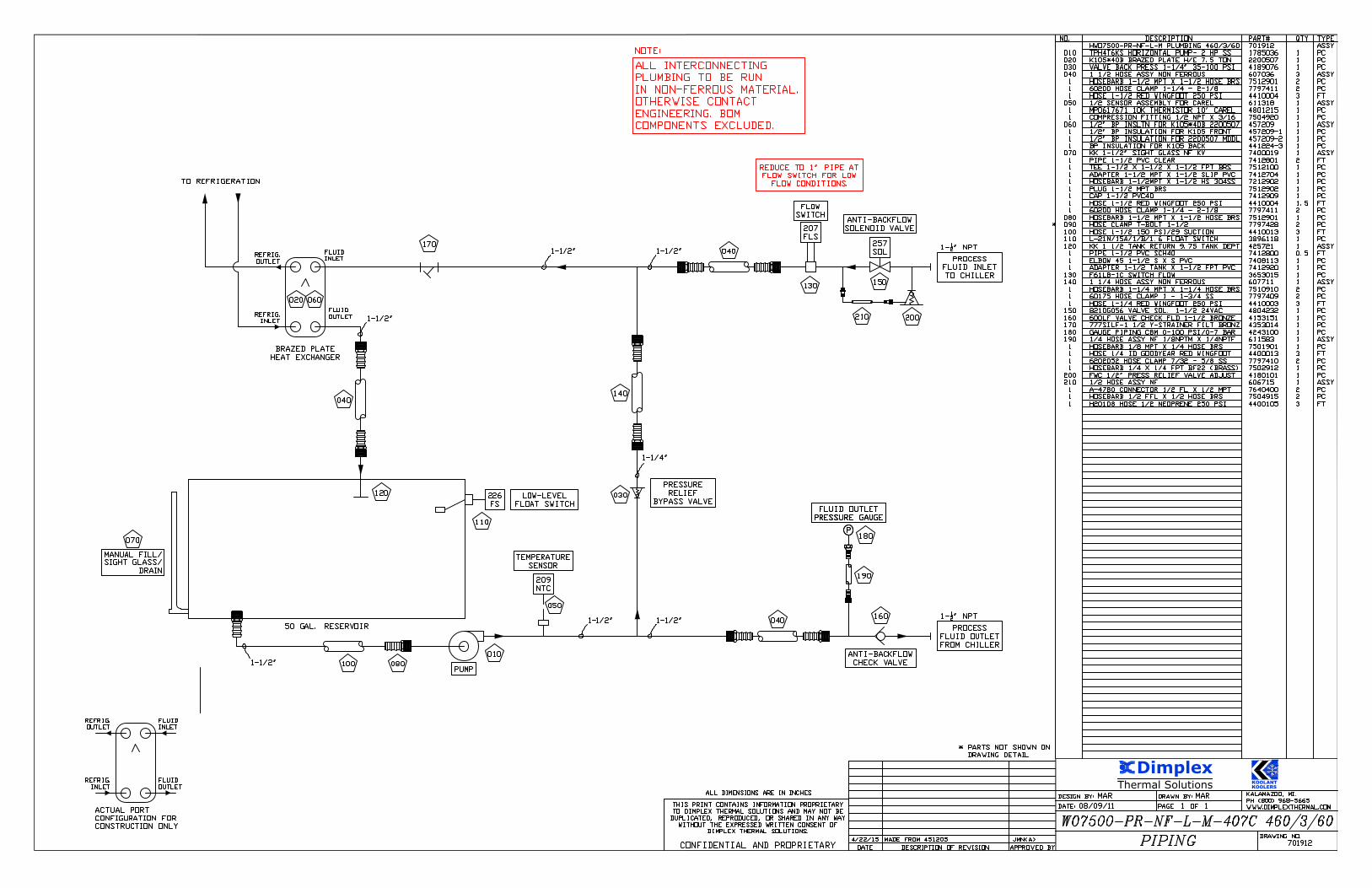
NO. DESCRIPTION PART# QTY TYPE HWO7500-PR-NF-L-M PLUMBING 460/3/60 701912 ASSY 010 TPH4T6KS HORIZONTAL PUMP- 2 HP SS 1785036 1 PC 020 K105*40B BRAZED PLATE H/E 7.5 TON 2200507 1 PC 030 VALVE BACK PRESS 1-1/4" 35-100 PSI 4189076 1 PC 040 1 1/2 HOSE ASSY NON FERROUS 607036 3 ASSY 1 HOSEBARB 1-1/2 MPT X 1-1/2 HOSE BRS 7512901 2 PC 1 60200 HOSE CLAMP 1-1/4 - 2-1/8 7797411 2 PC 1 HOSE 1-1/2 RED WINGFOOT 250 PSI 4410004 3 FT 050 1/2 SENSOR ASSEMBLY FOR CAREL 611318 1 ASSY 1 MP0617671 10K THERMISTOR 10' CAREL 4801215 1 PC 1 COMPRESSION FITTING 1/2 NPT X 3/16 7504920 1 PC 060 1/2" BP INSLTN FOR K105*40B 2200507 457209 1 ASSY 1 1/2" BP INSULATION FOR K105 FRONT 457209-1 1 PC 1 1/2" BP INSULATION FOR 2200507 MDDL 457209-2 1 PC 1 BP INSULATION FOR K105 BACK 441224-3 1 PC 070 KK 1-1/2" SIGHT GLASS NF KV 7400019 1 ASSY 1 PIPE 1-1/2 PVC CLEAR 7412801 2 FT 1 TEE 1-1/2 X 1-1/2 X 1-1/2 FPT BRS 7512100 1 PC 1 ADAPTER 1-1/2 MPT X 1-1/2 SLIP PVC 7412704 1 PC 1 HOSEBARB 1-1/2MPT X 1-1/2 HS 304SS 7212902 1 PC 1 PLUG 1-1/2 MPT BRS 7512902 1 PC 1 CAP 1-1/2 PVC40 7412909 1 PC 1 HOSE 1-1/2 RED WINGFOOT 250 PSI 4410004 1.5 FT 1 60200 HOSE CLAMP 1-1/4 - 2-1/8 7797411 2 PC 080 HOSEBARB 1-1/2 MPT X 1-1/2 HOSE BRS 7512901 1 PC 090 HOSE CLAMP T-BOLT 1-1/2 7797428 2 PC 100 HOSE 1-1/2 150 PSI/29 SUCTION 4410013 3 FT 110 L-21N/15A/1/B/1.6 FLOAT SWITCH 3896118 1 PC 120 KK 1 1/2 TANK RETURN 9.75 TANK DEPT 425721 1 ASSY 1 PIPE 1-1/2 PVC SCH40 7412800 0.5 FT 1 ELBOW 45 1-1/2 S X S PVC 7408113 1 PC 1 ADAPTER 1-1/2 TANK X 1-1/2 FPT PVC 7412920 1 PC 130 F61LB-1C SWITCH FLOW 3653015 1 PC 140 1 1/4 HOSE ASSY NON FERROUS 607711 1 ASSY 1 HOSEBARB 1-1/4 MPT X 1-1/4 HOSE BRS 7510910 2 PC 1 60175 HOSE CLAMP 1 - 1-3/4 SS 7797409 2 PC 1 HOSE 1-1/4 RED WINGFOOT 250 PSI 4410003 3 FT 150 8210G056 VALVE SOL. 1-1/2 24VAC 4804232 1 PC 160 600LF VALVE CHECK FLD 1-1/2 BRONZE 4153151 1 PC 170 777SILF-1 1/2 Y-STRAINER FILT BRONZ 4353014 1 PC 180 GAUGE PIPING CBM 0-100 PSI/0-7 BAR 4243100 1 PC 190 1/4 HOSE ASSY NF 1/8NPTM X 1/4NPTF 611583 1 ASSY 1 HOSEBARB 1/8 MPT X 1/4 HOSE BRS 7501901 1 PC 1 HOSE 1/4 ID GOODYEAR RED WINGFOOT 4400013 3 FT 1 6202052 HOSE CLAMP 7/32 - 5/8 SS 7797410 2 PC 1 HOSEBARB 1/4 X 1/4 FPT BF22 (BRASS) 7502912 1 PC 200 FWC 1/2" PRESS RELIEF VALVE ADJUST 4180101 1 PC 210 1/2 HOSE ASSY NF 606715 1 ASSY 1 A-4780 CONNECTOR 1/2 FL X 1/2 MPT 7640400 2 PC 1 HOSEBARB 1/2 FFL X 1/2 HOSE BRS 7504915 2 PC 1 H20108 HOSE 1/2 NEOPRENE 250 PSI 4400105 3 FT
AutoCAD SHX Text
KALAMAZOO, MI. PH (800) 968-5665 WWW.DIMPLEXTHERMAL.COM
AutoCAD SHX Text
DRAWING NO.
AutoCAD SHX Text
DESIGN BY:
AutoCAD SHX Text
DATE:
AutoCAD SHX Text
PAGE
AutoCAD SHX Text
DRAWN BY:
AutoCAD SHX Text
OF
AutoCAD SHX Text
DESCRIPTION OF REVISION
AutoCAD SHX Text
DATE
AutoCAD SHX Text
APPROVED BY
AutoCAD SHX Text
ALL DIMENSIONS ARE IN INCHES
AutoCAD SHX Text
THIS PRINT CONTAINS INFORMATION PROPRIETARY TO DIMPLEX THERMAL SOLUTIONS AND MAY NOT BE DUPLICATED, REPRODUCED, OR SHARED IN ANY WAY WITHOUT THE EXPRESSED WRITTEN CONSENT OF DIMPLEX THERMAL SOLUTIONS. CONFIDENTIAL AND PROPRIETARY
AutoCAD SHX Text
* PARTS NOT SHOWN ON
AutoCAD SHX Text
DRAWING DETAIL
AutoCAD SHX Text
MAR
AutoCAD SHX Text
MAR
AutoCAD SHX Text
1
AutoCAD SHX Text
1
AutoCAD SHX Text
08/09/11
AutoCAD SHX Text
701912
AutoCAD SHX Text
WO7500-PR-NF-L-M-407C 460/3/60
AutoCAD SHX Text
PIPING
AutoCAD SHX Text
4/22/15
AutoCAD SHX Text
MADE FROM 451205
AutoCAD SHX Text
JMN<A>
AutoCAD SHX Text
NOTE:
AutoCAD SHX Text
ALL INTERCONNECTING PLUMBING TO BE RUN IN NON-FERROUS MATERIAL. OTHERWISE CONTACT ENGINEERING. BOM COMPONENTS EXCLUDED.
AutoCAD SHX Text
070
AutoCAD SHX Text
SIGHT GLASS/
AutoCAD SHX Text
MANUAL FILL/
AutoCAD SHX Text
DRAIN
AutoCAD SHX Text
010
AutoCAD SHX Text
1-1/2"
AutoCAD SHX Text
PUMP
AutoCAD SHX Text
1-1/2"
AutoCAD SHX Text
REFRIG. INLET
AutoCAD SHX Text
REFRIG. OUTLET
AutoCAD SHX Text
FLUID OUTLET
AutoCAD SHX Text
FLUID INLET
AutoCAD SHX Text
ACTUAL PORT CONFIGURATION FOR CONSTRUCTION ONLY
AutoCAD SHX Text
REFRIG. INLET
AutoCAD SHX Text
REFRIG. OUTLET
AutoCAD SHX Text
FLUID OUTLET
AutoCAD SHX Text
FLUID INLET
AutoCAD SHX Text
020
AutoCAD SHX Text
1-1/2"
AutoCAD SHX Text
PRESSURE RELIEF BYPASS VALVE
AutoCAD SHX Text
PROCESS FLUID INLET TO CHILLER
AutoCAD SHX Text
1- " NPT12" NPT
AutoCAD SHX Text
TEMPERATURE SENSOR
AutoCAD SHX Text
209 NTC
AutoCAD SHX Text
050
AutoCAD SHX Text
030
AutoCAD SHX Text
140
AutoCAD SHX Text
1-1/4"
AutoCAD SHX Text
50 GAL. RESERVOIR
AutoCAD SHX Text
TO REFRIGERATION
AutoCAD SHX Text
BRAZED PLATE HEAT EXCHANGER
AutoCAD SHX Text
1-1/2"
AutoCAD SHX Text
040
AutoCAD SHX Text
LOW-LEVEL FLOAT SWITCH
AutoCAD SHX Text
226 FS
AutoCAD SHX Text
110
AutoCAD SHX Text
040
AutoCAD SHX Text
120
AutoCAD SHX Text
FLOW SWITCH
AutoCAD SHX Text
207 FLS
AutoCAD SHX Text
130
AutoCAD SHX Text
080
AutoCAD SHX Text
1-1/2"
AutoCAD SHX Text
040
AutoCAD SHX Text
PROCESS FLUID OUTLET FROM CHILLER
AutoCAD SHX Text
1- " NPT12" NPT
AutoCAD SHX Text
170
AutoCAD SHX Text
P
AutoCAD SHX Text
FLUID OUTLET PRESSURE GAUGE
AutoCAD SHX Text
180
AutoCAD SHX Text
190
AutoCAD SHX Text
P
AutoCAD SHX Text
FLUID OUTLET PRESSURE GAUGE
AutoCAD SHX Text
ANTI-BACKFLOW SOLENOID VALVE
AutoCAD SHX Text
257 SOL
AutoCAD SHX Text
ANTI-BACKFLOW CHECK VALVE
AutoCAD SHX Text
160
AutoCAD SHX Text
150
AutoCAD SHX Text
060
AutoCAD SHX Text
REDUCE TO 1" PIPE AT FLOW SWITCH FOR LOW FLOW CONDITIONS.
AutoCAD SHX Text
210
AutoCAD SHX Text
200
AutoCAD SHX Text
*
AutoCAD SHX Text
A
AutoCAD SHX Text
100
AutoCAD SHX Text
1-1/2"

Thermal Solutions
Dimplex
KOOLANTKOOLERS
AutoCAD SHX Text
1/4"
AutoCAD SHX Text
FAN
AutoCAD SHX Text
FLOW
AutoCAD SHX Text
AIR
AutoCAD SHX Text
1-1/8"
AutoCAD SHX Text
1-1/8"
AutoCAD SHX Text
7/8"
AutoCAD SHX Text
5/8"
AutoCAD SHX Text
5/8"
AutoCAD SHX Text
CONDENSER
AutoCAD SHX Text
SUB COOLER
AutoCAD SHX Text
7/8"
AutoCAD SHX Text
130
AutoCAD SHX Text
120
AutoCAD SHX Text
090
AutoCAD SHX Text
060
AutoCAD SHX Text
050
AutoCAD SHX Text
010
AutoCAD SHX Text
140
AutoCAD SHX Text
030
AutoCAD SHX Text
110
AutoCAD SHX Text
100
AutoCAD SHX Text
7/8"
AutoCAD SHX Text
080
AutoCAD SHX Text
040
AutoCAD SHX Text
TO PIPING
AutoCAD SHX Text
NO. DESCRIPTION PART# QTY TYPE HWO7500-PR-NF-L-M REFRIG 460/3/60 701913 ASSY 010 COMPRESSOR 7.5 TON 460/3/60 R-407C 612003 1 ASSY 1 C-SCN603H8K COMP 7.5 460/3/60 407C 1450077 1 PC 1 CRANKCASE HEATER 70 W 460 V 7.25 1298032 1 PC 020 VAF-8 VIBRATION ELIMINATOR 7/8 2980008 1 PC 030 SWITCH HIGH PRESSURE 450 MANUAL 3640017 1 PC 040 VALVE ANGLE REFRIG 7/8 3980003 1 PC 050 FAN ASSEMBLY 18"-5/8 1PH OUTDOOR 608586 2 ASSY 1 048A170F1H MOTOR 1/2 HP 1PH5/8 KEY 4051311 1 PC 1 61142601 FAN BLADE 18 5/8 KEY 4500035 1 PC 1 FAN GUARD MOUNT 18 DWG #101515 4507018 1 PC 1 FAN GUARD FULL 18 DWG #101516 4507019 1 PC 1 VENTURI 18" GALVANIZED DWG #201678 4504182 1 PC 1 CAP 5/8 DIA X 1-1/2 VINYL 4021315 1 BX 1 SILICONE SEALANT CLEAR 4508976 0.1 PC 1 BL50 LOCKNUT 1/2 TIGER GRIP STEEL 3800600 2 PC 1 CG-5050S CORD STRAIN RELIEF 3800471 2 PC 1 WIRE 14/3 SEOOW 600V BLACK 3807095 5 FT 060 COIL 7.5-10TON 42 X 41.5 W/ E-COAT 1413040 1 PC 070 FUSE TUBE COPPER/SOLDER 7399201 1 PC 080 VALVE ANGLE REFRIG 5/8 3980002 1 PC 090 C-165S FILTER DRIER 5/8" 2730006 1 PC 100 E10S250 VALVE SOLENOID 5/8" 2710006 1 PC 110 MKC-2E 24VAC 50-60 HZ COIL ASSEMBLY 608319 2 ASSY 1 MKC-2E SOLENOID COIL 24V AC 50/60HZ 2710113 1 PC 1 12205 CONNECTOR: DIN 43650 18MM W/ 4807100 1 PC 120 SA-15S SIGHT GLASS 5/8 ODF 2720004 1 PC 130 SNE-8-C VALVE EXPANSION R407C 2760005 1 PC 140 VAF-9 VIBRATION ELIMINATOR 1-1/8 2980009 1 PC 150 LOW PRESSURE SWITCH 10/20 3640006 1 PC 160 ADRHE-6-0/80 VALVE BYPASS 7/8 ODF 2740004 1 PC 170 E19S270 SOLENOID VALVE 7/8" 2710001 1 PC 180 P266SNR-1C TRANSDUCER 3646036 1 PC
AutoCAD SHX Text
251 SOL
AutoCAD SHX Text
LIQUID LINE SOLENOID VALVE
AutoCAD SHX Text
LIQUID LINE SIGHT GLASS
AutoCAD SHX Text
THERMOSTATIC EXPANSION VALVE
AutoCAD SHX Text
LIQUID LINE FILTER-DRIER
AutoCAD SHX Text
CONDENSER OUTLET VALVE
AutoCAD SHX Text
FUSE TUBE
AutoCAD SHX Text
CONDENSER INLET VALVE
AutoCAD SHX Text
COMPRESSOR
AutoCAD SHX Text
SUCTION LINE VIBRATION ELIMINATOR
AutoCAD SHX Text
223PS HIGH PRESSURE SWITCH
AutoCAD SHX Text
COMPRESSOR SUCTION SCHRADER PORT
AutoCAD SHX Text
DISCHARGE LINE VIBRATION ELIMINATOR
AutoCAD SHX Text
020
AutoCAD SHX Text
070
AutoCAD SHX Text
7/8"
AutoCAD SHX Text
252 SOL
AutoCAD SHX Text
HOT GAS REGULATOR
AutoCAD SHX Text
HOT GAS REGULATOR SOLENOID VALVE
AutoCAD SHX Text
7/8"
AutoCAD SHX Text
160
AutoCAD SHX Text
110
AutoCAD SHX Text
170
AutoCAD SHX Text
150
AutoCAD SHX Text
224PS LOW PRESSURE SWITCH
AutoCAD SHX Text
108PT VARIABLE SPEED
AutoCAD SHX Text
254PS FAN CYCLING
AutoCAD SHX Text
180
AutoCAD SHX Text
KALAMAZOO, MI. PH (800) 968-5665 WWW.DIMPLEXTHERMAL.COM
AutoCAD SHX Text
DRAWING NO.
AutoCAD SHX Text
DESIGN BY:
AutoCAD SHX Text
DATE:
AutoCAD SHX Text
PAGE
AutoCAD SHX Text
DRAWN BY:
AutoCAD SHX Text
OF
AutoCAD SHX Text
DESCRIPTION OF REVISION
AutoCAD SHX Text
DATE
AutoCAD SHX Text
APPROVED BY
AutoCAD SHX Text
ALL DIMENSIONS ARE IN INCHES
AutoCAD SHX Text
THIS PRINT CONTAINS INFORMATION PROPRIETARY TO DIMPLEX THERMAL SOLUTIONS AND MAY NOT BE DUPLICATED, REPRODUCED, OR SHARED IN ANY WAY WITHOUT THE EXPRESSED WRITTEN CONSENT OF DIMPLEX THERMAL SOLUTIONS. CONFIDENTIAL AND PROPRIETARY
AutoCAD SHX Text
* PARTS NOT SHOWN ON
AutoCAD SHX Text
DRAWING DETAIL
AutoCAD SHX Text
JMN
AutoCAD SHX Text
JMN
AutoCAD SHX Text
2
AutoCAD SHX Text
2
AutoCAD SHX Text
4/22/15
AutoCAD SHX Text
701913
AutoCAD SHX Text
WO7500-PR-NF-L-M-407C 460/3/60
AutoCAD SHX Text
REFRIGERATION
AutoCAD SHX Text
4/22/15
AutoCAD SHX Text
MADE FROM 454704
AutoCAD SHX Text
JMN<A>
AutoCAD SHX Text
A
Thermal Solutions
Dimplex
KOOLANTKOOLERS
AutoCAD SHX Text
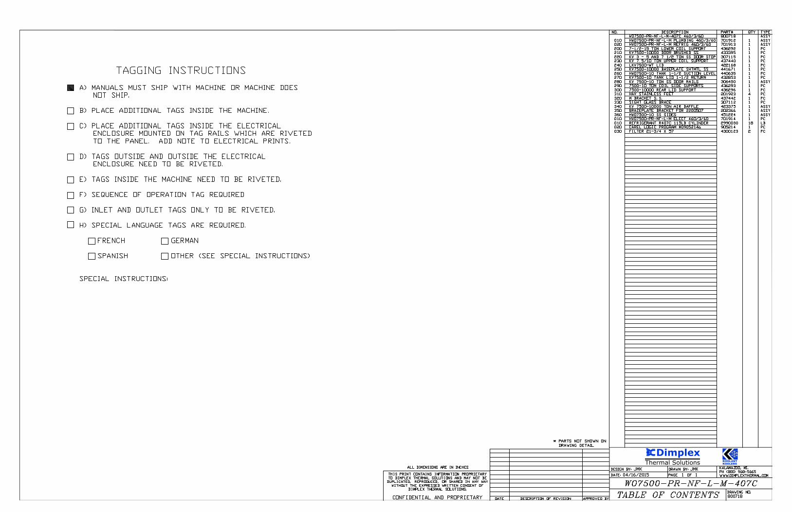
NO. DESCRIPTION PART# QTY TYPE DESCRIPTION PART# QTY TYPE WO7500-PR-NF-L-M-407C 460/3/60 800718 ASSY 010 HWO7500-PR-NF-L-M PLUMBING 460/3/60 701912 1 ASSY 020 HWO7500-PR-NF-L-M REFRIG 460/3/60 701913 1 ASSY 200 7-1/2-15 TON LOWER COIL SUPPORT 436292 1 PC 210 KV7500-10000 DOOR BRUSHED SS 433395 1 PC 220 KV 3 - 5 AND 7 1/2 TON SS DOOR STOP 307115 1 PC 230 KV 7.5/10 TON UPPER COIL SUPPORT 437440 1 PC 240 LKV7500-WT LID 422168 1 PC 250 KV7500-10000 BASEPLATE SHTMTL SS 441671 1 PC 260 HWO7500-10 TANK 1-1/2 SUCTION LEVEL 440635 1 PC 270 KV7500-10 TANK LID 1-1/2 RETURN 432853 1 PC 280 KV 7500-10 TON SS DOOR RAILS 306450 1 ASSY 290 7500-10 TON COIL SIDE SUPPORTS 436293 1 PC 300 7500-10000 REAR LID SUPPORT 436296 1 PC 310 HAV STAINLESS FEET 201923 4 PC 320 M BRACKET S.S. 437442 1 PC 330 SIGHT GLASS BRACE 307112 1 PC 340 KV 7500-10000 TON AIR BAFFLE 423375 1 ASSY 350 BRAZEPLATE BRACKET FOR 2200507 202366 1 ASSY 360 HWO7500-10 SS SIDES 451224 1 ASSY 010 HWO7500-PR-NF-L-M ELECT 460/3/60 701914 1 PC 010 REFRIGERANT R407C 115LB CYLINDER 2990030 18 LB 020 CAREL LOGIC PROGRAM #0905214a 905214 1 PC 030 FILTER 21-3/4 X 57 4300123 2 PC
AutoCAD SHX Text
KALAMAZOO, MI. PH (800) 968-5665 WWW.DIMPLEXTHERMAL.COM
AutoCAD SHX Text
DRAWING NO.
AutoCAD SHX Text
DESIGN BY:
AutoCAD SHX Text
DATE:
AutoCAD SHX Text
PAGE
AutoCAD SHX Text
DRAWN BY:
AutoCAD SHX Text
OF
AutoCAD SHX Text
DESCRIPTION OF REVISION
AutoCAD SHX Text
DATE
AutoCAD SHX Text
APPROVED BY
AutoCAD SHX Text
ALL DIMENSIONS ARE IN INCHES
AutoCAD SHX Text
THIS PRINT CONTAINS INFORMATION PROPRIETARY TO DIMPLEX THERMAL SOLUTIONS AND MAY NOT BE DUPLICATED, REPRODUCED, OR SHARED IN ANY WAY WITHOUT THE EXPRESSED WRITTEN CONSENT OF DIMPLEX THERMAL SOLUTIONS. CONFIDENTIAL AND PROPRIETARY
AutoCAD SHX Text
* PARTS NOT SHOWN ON
AutoCAD SHX Text
DRAWING DETAIL
AutoCAD SHX Text
JMK
AutoCAD SHX Text
JMK
AutoCAD SHX Text
1
AutoCAD SHX Text
1
AutoCAD SHX Text
04/16/2015
AutoCAD SHX Text
WO7500-PR-NF-L-M-407C
AutoCAD SHX Text
TABLE OF CONTENTS
AutoCAD SHX Text
800718
AutoCAD SHX Text
TAGGING INSTRUCTIONS TAGGING INSTRUCTIONS A) MANUALS MUST SHIP WITH MACHINE OR MACHINE DOES NOT SHIP. B) PLACE ADDITIONAL TAGS INSIDE THE MACHINE. C) PLACE ADDITIONAL TAGS INSIDE THE ELECTRICAL ENCLOSURE MOUNTED ON TAG RAILS WHICH ARE RIVETED TO THE PANEL. ADD NOTE TO ELECTRICAL PRINTS. D) TAGS OUTSIDE AND OUTSIDE THE ELECTRICAL ENCLOSURE NEED TO BE RIVETED. E) TAGS INSIDE THE MACHINE NEED TO BE RIVETED. F) SEQUENCE OF OPERATION TAG REQUIRED G) INLET AND OUTLET TAGS ONLY TO BE RIVETED. H) SPECIAL LANGUAGE TAGS ARE REQUIRED. FRENCHGERMAN GERMAN SPANISHOTHER (SEE SPECIAL INSTRUCTIONS) OTHER (SEE SPECIAL INSTRUCTIONS) SPECIAL INSTRUCTIONS:

Thermal Solutions
Dimplex
KOOLANTKOOLERS
AutoCAD SHX Text
NOTE: TAR TAPE IS ONLY TO BE USED ON THE SUCTION LINE VIBRATION ELIMINATOR. 1. BEFORE STARTING! SEE PLUMBING BOM FOR ANY PRE-CUT INSULATION BEFORE STARTING! SEE PLUMBING BOM FOR ANY PRE-CUT INSULATION 2. " INSULATION ON ALL TANK SURFACES EXCLUDING THE TOP OF RECTANGLE TANKS 12" INSULATION ON ALL TANK SURFACES EXCLUDING THE TOP OF RECTANGLE TANKS 3. " INSULATION ON ALL PLUMBING HEAT EXCHANGERS EXCLUDING SUBMERSED COIL 12" INSULATION ON ALL PLUMBING HEAT EXCHANGERS EXCLUDING SUBMERSED COIL 4. SINGLE LAYER TAR TAPE STARTING 2" BELOW SUCTION LINE VIBRATION ELIMINATOR ENDING 2" ABOVE VIBRATION ELIMINATOR 5. " INSULATION ON REFRIGERATION SUCTION LINE AND COMPONENTS STARTING AT 12" INSULATION ON REFRIGERATION SUCTION LINE AND COMPONENTS STARTING AT THE BOTTOM 6. " INSULATION ON ALL PLUMBING COMPONENTS EXCLUDING CLEAR PORTION OF 12" INSULATION ON ALL PLUMBING COMPONENTS EXCLUDING CLEAR PORTION OF SIGHT GLASS 7. " INSULATION ON HEATER SHEATHS 12" INSULATION ON HEATER SHEATHS 8. SHELL AND TUBE WATER COOLED CONDENSER AND WATER COOLED CONDENSER PIPING NOT TO BE INSULATED.
AutoCAD SHX Text
KALAMAZOO, MI. PH (800) 968-5665 WWW.DIMPLEXTHERMAL.COM
AutoCAD SHX Text
DRAWING NO.
AutoCAD SHX Text
DESIGN BY:
AutoCAD SHX Text
DATE:
AutoCAD SHX Text
PAGE
AutoCAD SHX Text
DRAWN BY:
AutoCAD SHX Text
OF
AutoCAD SHX Text
DESCRIPTION OF REVISION
AutoCAD SHX Text
DATE
AutoCAD SHX Text
APPR
AutoCAD SHX Text
THIS PRINT CONTAINS INFORMATION PROPRIETARY TO DIMPLEX THERMAL SOLUTIONS AND MAY NOT BE DUPLICATED, REPRODUCED, OR SHARED IN ANY WAY WITHOUT THE EXPRESSED WRITTEN CONSENT OF DIMPLEX THERMAL SOLUTIONS. CONFIDENTIAL AND PROPRIETARY
AutoCAD SHX Text
ALL DIMENSIONS ARE IN INCHES
AutoCAD SHX Text
* PARTS NOT SHOWN ON
AutoCAD SHX Text
DRAWING DETAIL
AutoCAD SHX Text
ECO #
AutoCAD SHX Text
A
AutoCAD SHX Text
B
AutoCAD SHX Text
C
AutoCAD SHX Text
D
AutoCAD SHX Text
E
AutoCAD SHX Text
F
AutoCAD SHX Text
G
AutoCAD SHX Text
H
AutoCAD SHX Text
I
AutoCAD SHX Text
J
AutoCAD SHX Text
K
AutoCAD SHX Text
REV
AutoCAD SHX Text
MAB
AutoCAD SHX Text
MAB
AutoCAD SHX Text
9/30/13
AutoCAD SHX Text
1
AutoCAD SHX Text
1
AutoCAD SHX Text
INSULATION PACKAGE
AutoCAD SHX Text
C
AutoCAD SHX Text
457695
AutoCAD SHX Text
1141
AutoCAD SHX Text
7/30/15
AutoCAD SHX Text
ADDED WATER COOLED CONDENSER NOTE
AutoCAD SHX Text
AJM
AutoCAD SHX Text
NO. ID/DESCRIPTION K.K.PART# QTY TYPE
AutoCAD SHX Text
A
Thermal Solutions
Dimplex
KOOLANTKOOLERS
AutoCAD SHX Text
GND
AutoCAD SHX Text
ELECTRICAL PANEL
AutoCAD SHX Text
ELECTRICAL BOX
AutoCAD SHX Text
010
AutoCAD SHX Text
020
AutoCAD SHX Text
030
AutoCAD SHX Text
140
AutoCAD SHX Text
130
AutoCAD SHX Text
190
AutoCAD SHX Text
255HTR
AutoCAD SHX Text
110
AutoCAD SHX Text
060
AutoCAD SHX Text
050
AutoCAD SHX Text
090
AutoCAD SHX Text
070
AutoCAD SHX Text
T1
AutoCAD SHX Text
T2
AutoCAD SHX Text
NC
AutoCAD SHX Text
NO
AutoCAD SHX Text
T1
AutoCAD SHX Text
T2
AutoCAD SHX Text
T3
AutoCAD SHX Text
L1
AutoCAD SHX Text
A1
AutoCAD SHX Text
L2
AutoCAD SHX Text
L3
AutoCAD SHX Text
A2
AutoCAD SHX Text
T3
AutoCAD SHX Text
RESET
AutoCAD SHX Text
NO
AutoCAD SHX Text
NO
AutoCAD SHX Text
238M
AutoCAD SHX Text
122OL
AutoCAD SHX Text
T1
AutoCAD SHX Text
T2
AutoCAD SHX Text
T3
AutoCAD SHX Text
NO
AutoCAD SHX Text
L1
AutoCAD SHX Text
L2
AutoCAD SHX Text
A1
AutoCAD SHX Text
L3
AutoCAD SHX Text
NO
AutoCAD SHX Text
A2
AutoCAD SHX Text
239CON
AutoCAD SHX Text
160
AutoCAD SHX Text
180
AutoCAD SHX Text
150
AutoCAD SHX Text
CR
AutoCAD SHX Text
240
AutoCAD SHX Text
170
AutoCAD SHX Text
080
AutoCAD SHX Text
T1
AutoCAD SHX Text
T2
AutoCAD SHX Text
T3
AutoCAD SHX Text
NO
AutoCAD SHX Text
L1
AutoCAD SHX Text
L2
AutoCAD SHX Text
A1
AutoCAD SHX Text
L3
AutoCAD SHX Text
NO
AutoCAD SHX Text
A2
AutoCAD SHX Text
254CON
AutoCAD SHX Text
160
AutoCAD SHX Text
254PS
AutoCAD SHX Text
P70
AutoCAD SHX Text
200
AutoCAD SHX Text
126FU1
AutoCAD SHX Text
126FU2
AutoCAD SHX Text
CR
AutoCAD SHX Text
245
AutoCAD SHX Text
Esc
AutoCAD SHX Text
Prg
AutoCAD SHX Text
CAREL
AutoCAD SHX Text
pCO built-in terminal
AutoCAD SHX Text
B3
AutoCAD SHX Text
J2
AutoCAD SHX Text
J1
AutoCAD SHX Text
B2
AutoCAD SHX Text
B1
AutoCAD SHX Text
SYNC
AutoCAD SHX Text
G
AutoCAD SHX Text
G0
AutoCAD SHX Text
+5VREF
AutoCAD SHX Text
-5VREF
AutoCAD SHX Text
J3
AutoCAD SHX Text
J4
AutoCAD SHX Text
Y3
AutoCAD SHX Text
Y1
AutoCAD SHX Text
Y2
AutoCAD SHX Text
B4
AutoCAD SHX Text
GND
AutoCAD SHX Text
IDC1
AutoCAD SHX Text
ID5
AutoCAD SHX Text
ID3
AutoCAD SHX Text
ID4
AutoCAD SHX Text
ID1
AutoCAD SHX Text
ID2
AutoCAD SHX Text
GND
AutoCAD SHX Text
ID6
AutoCAD SHX Text
RX/TX+
AutoCAD SHX Text
RX/TX-
AutoCAD SHX Text
GND
AutoCAD SHX Text
J7
AutoCAD SHX Text
J6
AutoCAD SHX Text
NO2
AutoCAD SHX Text
NO1
AutoCAD SHX Text
C1
AutoCAD SHX Text
GND
AutoCAD SHX Text
TLAN
AutoCAD SHX Text
C5
AutoCAD SHX Text
NO5
AutoCAD SHX Text
NO3
AutoCAD SHX Text
NO4
AutoCAD SHX Text
C4
AutoCAD SHX Text
NC5
AutoCAD SHX Text
J9
AutoCAD SHX Text
J8
AutoCAD SHX Text
J11
AutoCAD SHX Text
J10
AutoCAD SHX Text
130FU
AutoCAD SHX Text
100
AutoCAD SHX Text
220
AutoCAD SHX Text
108PS
AutoCAD SHX Text
INSIDE THE ENCLOSURE
AutoCAD SHX Text
BEFORE DRILLING HOLE
AutoCAD SHX Text
CONNECTION LOCATION
AutoCAD SHX Text
CHECK FOR CLEARANCES
AutoCAD SHX Text
3/4" CONDUIT MINIMUM
AutoCAD SHX Text
FIELD WIRING
AutoCAD SHX Text
Dimplex Thermal Solutions
AutoCAD SHX Text
2625 Emerald Drive
AutoCAD SHX Text
Kalamazoo, Michigan 49001-4542
AutoCAD SHX Text
Phone: (269) 349-6800 Fax: 349-8951
AutoCAD SHX Text
---------------------------------
AutoCAD SHX Text
---------------------------------
AutoCAD SHX Text
H.P. FLA(Amps) LRA(Amps)
AutoCAD SHX Text
--------- --- ------- -------
AutoCAD SHX Text
---------------------------------
AutoCAD SHX Text
REFRIGERATION
AutoCAD SHX Text
Design Pressure
AutoCAD SHX Text
WARNING: RISK OF ELECTRICAL SHOCK. CAN CAUSE
AutoCAD SHX Text
INJURY OR DEATH: DISCONNECT ALL REMOTE
AutoCAD SHX Text
---------------------------------
AutoCAD SHX Text
ELECTRICAL POWER SUPPLIES BEFORE SERVICING.
AutoCAD SHX Text
Model: WO7500-PR-NF-L-M-407C
AutoCAD SHX Text
Serial:
AutoCAD SHX Text
460 VOLT-3 PHASE-60HZ
AutoCAD SHX Text
1 Compressor
AutoCAD SHX Text
7.5
AutoCAD SHX Text
16.5
AutoCAD SHX Text
84
AutoCAD SHX Text
1 Pump
AutoCAD SHX Text
2
AutoCAD SHX Text
5.8
AutoCAD SHX Text
2 Fans
AutoCAD SHX Text
1/2
AutoCAD SHX Text
1.2
AutoCAD SHX Text
Minimum Circuit Ampacity: 30 Amps
AutoCAD SHX Text
Maximum Overcurrent Protection: 50 Amps
AutoCAD SHX Text
Refrigerant: R-407C
AutoCAD SHX Text
Pounds: 18 Lbs
AutoCAD SHX Text
High Side: 350 PSI
AutoCAD SHX Text
Low Side: 70 PSI
AutoCAD SHX Text
Manufactured:
AutoCAD SHX Text
Outdoor Use
AutoCAD SHX Text
SCCR: 5 kA
AutoCAD SHX Text
UTILISER DES FILS D`ALIMENTATION EN CUIVRE.
AutoCAD SHX Text
USE COPPER SUPPLY WIRES
AutoCAD SHX Text
CAUTION: USE TIME DELAY FUSES.
AutoCAD SHX Text
ATTENTION: UTILISER DES FUSIBLES TEMPORISES
AutoCAD SHX Text
LISTING # KOO1995
AutoCAD SHX Text
COMPLIES WITH
AutoCAD SHX Text
UL 1995
AutoCAD SHX Text
MET
AutoCAD SHX Text
NRTL LISTED
AutoCAD SHX Text
LISTING # KOO1995
AutoCAD SHX Text
COMPLIES WITH
AutoCAD SHX Text
UL 1995
AutoCAD SHX Text
MET
AutoCAD SHX Text
NRTL LISTED
AutoCAD SHX Text
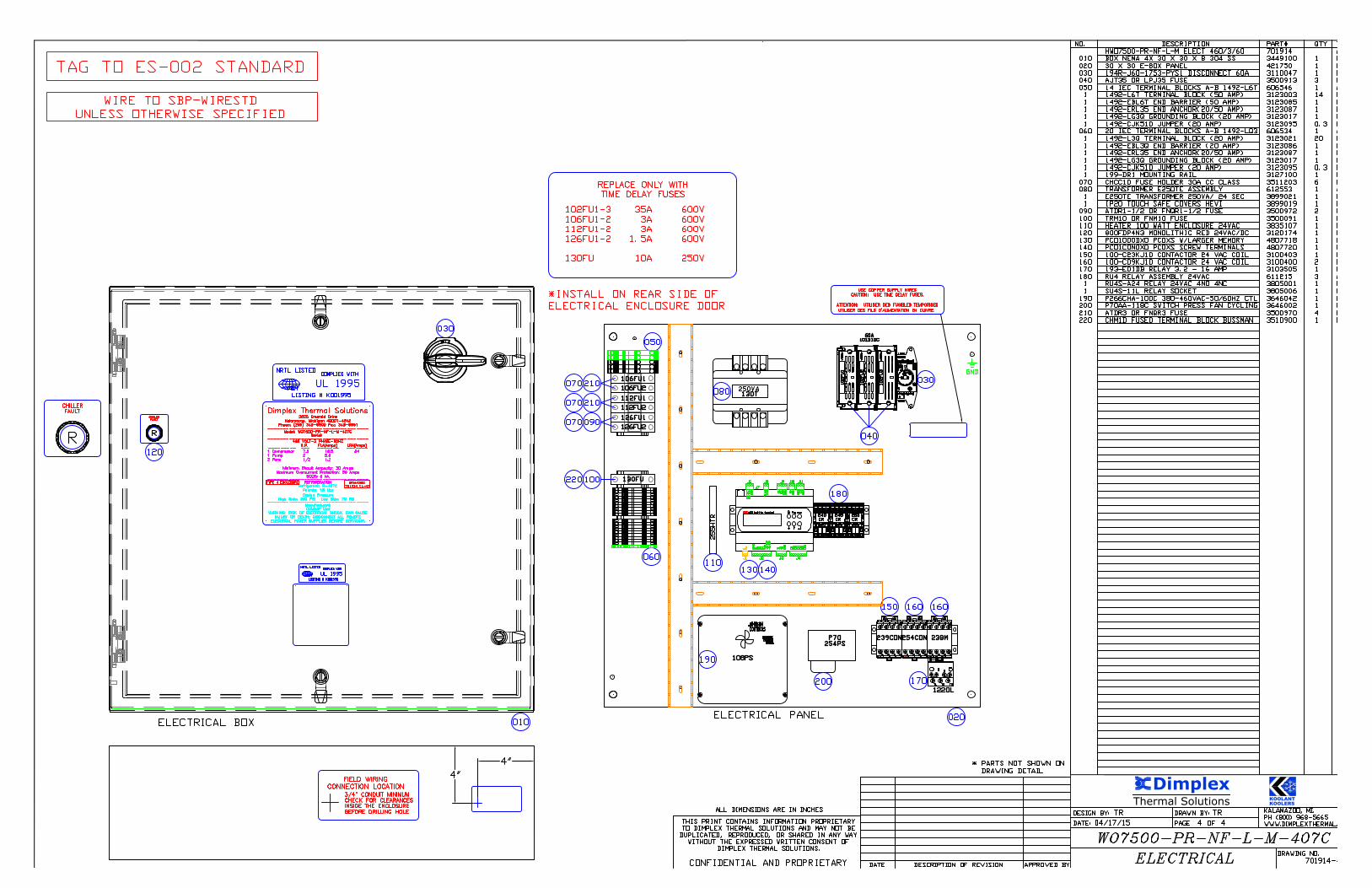
102FU1-3 35A600V 600V 106FU1-2 3A600V 600V 112FU1-2 3A600V 600V 126FU1-2 1.5A600V 600V 130FU 10A250V 10A250V250V
AutoCAD SHX Text
REPLACE ONLY WITH TIME DELAY FUSES
AutoCAD SHX Text
*INSTALL ON REAR SIDE OF ELECTRICAL ENCLOSURE DOOR
AutoCAD SHX Text
120
AutoCAD SHX Text
CHILLER
AutoCAD SHX Text
FAULT
AutoCAD SHX Text
R
AutoCAD SHX Text
R
AutoCAD SHX Text
CHILLER
AutoCAD SHX Text
FAULT
AutoCAD SHX Text
CR
AutoCAD SHX Text
253
AutoCAD SHX Text
DRAWINGS 701914 (1-4)
AutoCAD SHX Text
TYPE 4 ENCLOSURE
AutoCAD SHX Text
250VA
AutoCAD SHX Text
130T
AutoCAD SHX Text
112FU1
AutoCAD SHX Text
112FU2
AutoCAD SHX Text
106FU1
AutoCAD SHX Text
106FU2
AutoCAD SHX Text
210
AutoCAD SHX Text
070
AutoCAD SHX Text
070
AutoCAD SHX Text
030
AutoCAD SHX Text
040
AutoCAD SHX Text
101DISC
AutoCAD SHX Text
60A
AutoCAD SHX Text
102FU3
AutoCAD SHX Text
102FU2
AutoCAD SHX Text
102FU1
AutoCAD SHX Text
210
AutoCAD SHX Text
KALAMAZOO, MI. PH (800) 968-5665 WWW.DIMPLEXTHERMAL.COM
AutoCAD SHX Text
DRAWING NO.
AutoCAD SHX Text
DESIGN BY:
AutoCAD SHX Text
DATE:
AutoCAD SHX Text
PAGE
AutoCAD SHX Text
DRAWN BY:
AutoCAD SHX Text
OF
AutoCAD SHX Text
DESCRIPTION OF REVISION
AutoCAD SHX Text
DATE
AutoCAD SHX Text
APPROVED BY
AutoCAD SHX Text
ALL DIMENSIONS ARE IN INCHES
AutoCAD SHX Text
THIS PRINT CONTAINS INFORMATION PROPRIETARY TO DIMPLEX THERMAL SOLUTIONS AND MAY NOT BE DUPLICATED, REPRODUCED, OR SHARED IN ANY WAY WITHOUT THE EXPRESSED WRITTEN CONSENT OF DIMPLEX THERMAL SOLUTIONS. CONFIDENTIAL AND PROPRIETARY
AutoCAD SHX Text
* PARTS NOT SHOWN ON
AutoCAD SHX Text
DRAWING DETAIL
AutoCAD SHX Text
TR
AutoCAD SHX Text
TR
AutoCAD SHX Text
4
AutoCAD SHX Text
4
AutoCAD SHX Text
04/17/15
AutoCAD SHX Text
701914-4
AutoCAD SHX Text
WO7500-PR-NF-L-M-407C
AutoCAD SHX Text
ELECTRICAL
AutoCAD SHX Text
NO. DESCRIPTION PART# QTY TYPE HWO7500-PR-NF-L-M ELECT 460/3/60 701914 ASSY 010 BOX NEMA 4X 30 X 30 X 8 304 SS 3449100 1 PC 020 30 X 30 E-BOX PANEL 421750 1 PC 030 194R-J60-1753-PYS1 DISCONNECT 60A 3110047 1 PC 040 AJT35 OR LPJ35 FUSE 3500913 3 PC 050 14 IEC TERMINAL BLOCKS A-B 1492-L6T 606546 1 ASSY 1 1492-L6T TERMINAL BLOCK (50 AMP) 3123003 14 PC 1 1492-EBL6T END BARRIER (50 AMP) 3123085 1 PC 1 1492-ERL35 END ANCHOR(20/50 AMP) 3123087 1 PC 1 1492-LG3Q GROUNDING BLOCK (20 AMP) 3123017 1 PC 1 1492-CJK510 JUMPER (20 AMP) 3123095 0.3 PC 060 20 IEC TERMINAL BLOCKS A-B 1492-LQ3 606534 1 ASSY 1 1492-L3Q TERMINAL BLOCK (20 AMP) 3123021 20 PC 1 1492-EBL3Q END BARRIER (20 AMP) 3123086 1 PC 1 1492-ERL35 END ANCHOR(20/50 AMP) 3123087 1 PC 1 1492-LG3Q GROUNDING BLOCK (20 AMP) 3123017 1 PC 1 1492-CJK510 JUMPER (20 AMP) 3123095 0.3 PC 1 199-DR1 MOUNTING RAIL 3127100 1 PC 070 CHCC1D FUSE HOLDER 30A CC CLASS 3511203 6 PC 080 TRANSFORMER E250TE ASSEMBLY 612553 1 ASSY 1 E250TE TRANSFORMER 250VA/ 24 SEC 3899021 1 PC 1 IP20 TOUCH SAFE COVERS HEVI 3899019 1 PC 090 ATDR1-1/2 OR FNQR1-1/2 FUSE 3500972 2 PC 100 TRM10 OR FNM10 FUSE 3500091 1 PC 110 HEATER 100 WATT ENCLOSURE 24VAC 3835107 1 PC 120 800FDP4N3 MONOLITHIC RED 24VAC/DC 3120174 1 PC 130 PCO1000DX0 PCOXS W/LARGER MEMORY 4807718 1 PC 140 PCO1CON0X0 PCOXS SCREW TERMINALS 4807720 1 PC 150 100-C23KJ10 CONTACTOR 24 VAC COIL 3100403 1 PC 160 100-C09KJ10 CONTACTOR 24 VAC COIL 3100400 2 PC 170 193-ED1DB RELAY 3.2 - 16 AMP 3103505 1 PC 180 RU4 RELAY ASSEMBLY 24VAC 611215 3 ASSY 1 RU4S-A24 RELAY 24VAC 4NO 4NC 3805001 1 PC 1 SU4S-11L RELAY SOCKET 3805006 1 PC 190 P266CHA-100C 380-460VAC-50/60HZ CTL 3646042 1 PC 200 P70AA-118C SWITCH PRESS FAN CYCLING 3646002 1 PC 210 ATDR3 OR FNQR3 FUSE 3500970 4 PC 220 CHM1D FUSED TERMINAL BLOCK BUSSMAN 3510900 1 PC
AutoCAD SHX Text
TAG TO ES-002 STANDARD
AutoCAD SHX Text
WIRE TO SBP-WIRESTD UNLESS OTHERWISE SPECIFIED
Thermal Solutions
Dimplex
KOOLANTKOOLERS
AutoCAD SHX Text
1
AutoCAD SHX Text
01
AutoCAD SHX Text
1
AutoCAD SHX Text
02
AutoCAD SHX Text
1
AutoCAD SHX Text
03
AutoCAD SHX Text
1
AutoCAD SHX Text
05
AutoCAD SHX Text
1
AutoCAD SHX Text
04
AutoCAD SHX Text
1
AutoCAD SHX Text
09
AutoCAD SHX Text
1
AutoCAD SHX Text
08
AutoCAD SHX Text
1
AutoCAD SHX Text
07
AutoCAD SHX Text
1
AutoCAD SHX Text
06
AutoCAD SHX Text
1
AutoCAD SHX Text
17
AutoCAD SHX Text
1
AutoCAD SHX Text
16
AutoCAD SHX Text
1
AutoCAD SHX Text
15
AutoCAD SHX Text
1
AutoCAD SHX Text
14
AutoCAD SHX Text
1
AutoCAD SHX Text
13
AutoCAD SHX Text
1
AutoCAD SHX Text
12
AutoCAD SHX Text
1
AutoCAD SHX Text
11
AutoCAD SHX Text
1
AutoCAD SHX Text
10
AutoCAD SHX Text
1
AutoCAD SHX Text
19
AutoCAD SHX Text
1
AutoCAD SHX Text
18
AutoCAD SHX Text
1
AutoCAD SHX Text
20
AutoCAD SHX Text
460V / 3PH / 60HZ
AutoCAD SHX Text
101DISC
AutoCAD SHX Text
60AMP
AutoCAD SHX Text
35A
AutoCAD SHX Text
102FU3
AutoCAD SHX Text
102FU2
AutoCAD SHX Text
102FU1
AutoCAD SHX Text
102L1
AutoCAD SHX Text
102L2
AutoCAD SHX Text
102L3
AutoCAD SHX Text
MTR1
AutoCAD SHX Text
103T3
AutoCAD SHX Text
103T1
AutoCAD SHX Text
103T2
AutoCAD SHX Text
239CON
AutoCAD SHX Text
1
AutoCAD SHX Text
37
AutoCAD SHX Text
1
AutoCAD SHX Text
38
AutoCAD SHX Text
1
AutoCAD SHX Text
36
AutoCAD SHX Text
1
AutoCAD SHX Text
34
AutoCAD SHX Text
1
AutoCAD SHX Text
35
AutoCAD SHX Text
1
AutoCAD SHX Text
32
AutoCAD SHX Text
1
AutoCAD SHX Text
33
AutoCAD SHX Text
1
AutoCAD SHX Text
31
AutoCAD SHX Text
1
AutoCAD SHX Text
24
AutoCAD SHX Text
1
AutoCAD SHX Text
27
AutoCAD SHX Text
1
AutoCAD SHX Text
29
AutoCAD SHX Text
1
AutoCAD SHX Text
30
AutoCAD SHX Text
1
AutoCAD SHX Text
28
AutoCAD SHX Text
1
AutoCAD SHX Text
26
AutoCAD SHX Text
1
AutoCAD SHX Text
25
AutoCAD SHX Text
1
AutoCAD SHX Text
23
AutoCAD SHX Text
1
AutoCAD SHX Text
22
AutoCAD SHX Text
1
AutoCAD SHX Text
21
AutoCAD SHX Text
238M
AutoCAD SHX Text
122T1
AutoCAD SHX Text
122T3
AutoCAD SHX Text
122T2
AutoCAD SHX Text
122OL
AutoCAD SHX Text
MTR4
AutoCAD SHX Text
1
AutoCAD SHX Text
21
AutoCAD SHX Text
1
AutoCAD SHX Text
21
AutoCAD SHX Text
1
AutoCAD SHX Text
20
AutoCAD SHX Text
1
AutoCAD SHX Text
20
AutoCAD SHX Text
126FU1
AutoCAD SHX Text
126FU2
AutoCAD SHX Text
1.5A
AutoCAD SHX Text
126L2
AutoCAD SHX Text
126L1
AutoCAD SHX Text
102L2
AutoCAD SHX Text
102L1
AutoCAD SHX Text
102L1
AutoCAD SHX Text
102L2
AutoCAD SHX Text
1
AutoCAD SHX Text
20
AutoCAD SHX Text
102L3
AutoCAD SHX Text
1
AutoCAD SHX Text
21
AutoCAD SHX Text
102L3
AutoCAD SHX Text
KALAMAZOO, MI. PH (800) 968-5665 WWW.DIMPLEXTHERMAL.COM
AutoCAD SHX Text
DRAWING NO.
AutoCAD SHX Text
DESIGN BY:
AutoCAD SHX Text
DATE:
AutoCAD SHX Text
PAGE
AutoCAD SHX Text
DRAWN BY:
AutoCAD SHX Text
OF
AutoCAD SHX Text
DESCRIPTION OF REVISION
AutoCAD SHX Text
DATE
AutoCAD SHX Text
APPROVED BY
AutoCAD SHX Text
ALL DIMENSIONS ARE IN INCHES
AutoCAD SHX Text
THIS PRINT CONTAINS INFORMATION PROPRIETARY TO DIMPLEX THERMAL SOLUTIONS AND MAY NOT BE DUPLICATED, REPRODUCED, OR SHARED IN ANY WAY WITHOUT THE EXPRESSED WRITTEN CONSENT OF DIMPLEX THERMAL SOLUTIONS. CONFIDENTIAL AND PROPRIETARY
AutoCAD SHX Text
TR
AutoCAD SHX Text
TR
AutoCAD SHX Text
1
AutoCAD SHX Text
4
AutoCAD SHX Text
04/17/15
AutoCAD SHX Text
701914-1
AutoCAD SHX Text
WO7500-PR-NF-L-M-407C
AutoCAD SHX Text
ELECTRICAL
AutoCAD SHX Text
106L1
AutoCAD SHX Text
106L2
AutoCAD SHX Text
107C
AutoCAD SHX Text
106T1
AutoCAD SHX Text
MTR2
AutoCAD SHX Text
1
AutoCAD SHX Text
10
AutoCAD SHX Text
1
AutoCAD SHX Text
10
AutoCAD SHX Text
HEATER
AutoCAD SHX Text
70 W
AutoCAD SHX Text
CRANKCASE
AutoCAD SHX Text
254CON
AutoCAD SHX Text
MTR3
AutoCAD SHX Text
112T2
AutoCAD SHX Text
112T1
AutoCAD SHX Text
2
AutoCAD SHX Text
42
AutoCAD SHX Text
2
AutoCAD SHX Text
37
AutoCAD SHX Text
2
AutoCAD SHX Text
37
AutoCAD SHX Text
2
AutoCAD SHX Text
48
AutoCAD SHX Text
2
AutoCAD SHX Text
48
AutoCAD SHX Text
113C
AutoCAD SHX Text
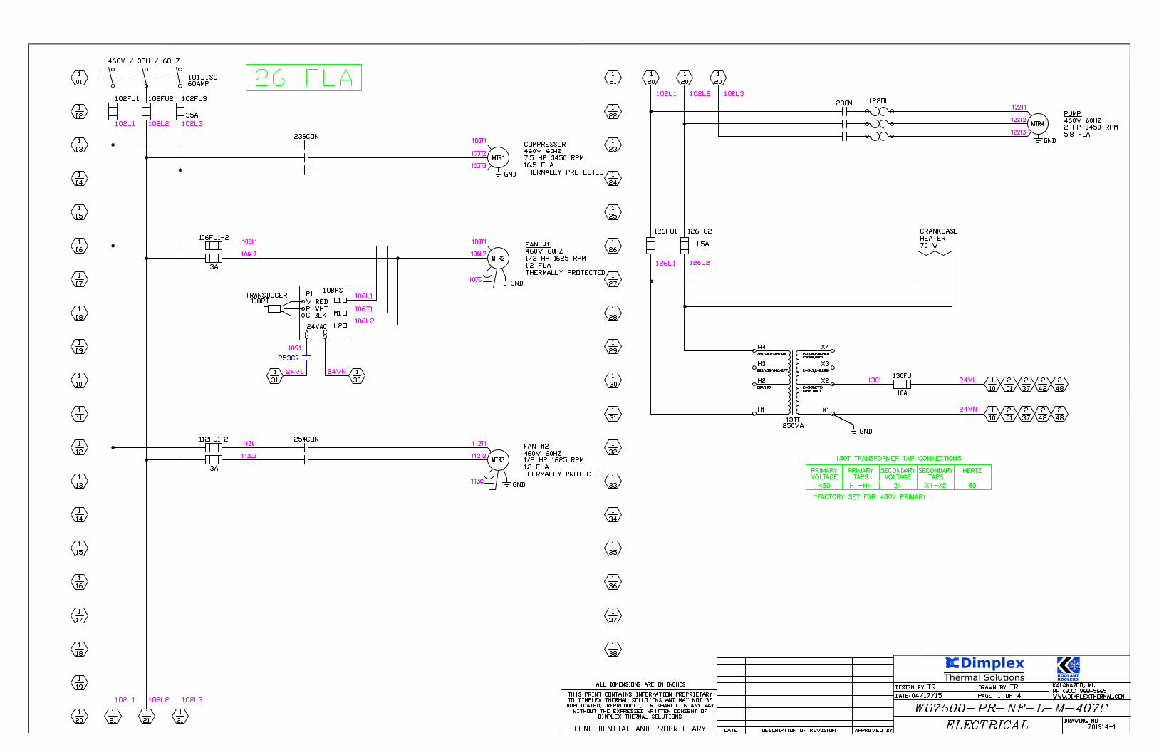
26 FLA
AutoCAD SHX Text
PUMP 460V 60HZ 2 HP 3450 RPM 5.8 FLA
AutoCAD SHX Text
COMPRESSOR 460V 60HZ 7.5 HP 3450 RPM 16.5 FLA THERMALLY PROTECTED
AutoCAD SHX Text
FAN #1 460V 60HZ 1/2 HP 1625 RPM 1.2 FLA THERMALLY PROTECTED
AutoCAD SHX Text
FAN #2 460V 60HZ 1/2 HP 1625 RPM 1.2 FLA THERMALLY PROTECTED
AutoCAD SHX Text
106T1
AutoCAD SHX Text
106L2
AutoCAD SHX Text
GND
AutoCAD SHX Text
GND
AutoCAD SHX Text
GND
AutoCAD SHX Text
GND
AutoCAD SHX Text
2
AutoCAD SHX Text
01
AutoCAD SHX Text
2
AutoCAD SHX Text
01
AutoCAD SHX Text
253CR
AutoCAD SHX Text
1
AutoCAD SHX Text
31
AutoCAD SHX Text
1
AutoCAD SHX Text
30
AutoCAD SHX Text
2
AutoCAD SHX Text
42
AutoCAD SHX Text
24VAC
AutoCAD SHX Text
M1
AutoCAD SHX Text
L1
AutoCAD SHX Text
C BLK
AutoCAD SHX Text
V RED
AutoCAD SHX Text
P WHT
AutoCAD SHX Text
P1
AutoCAD SHX Text
A
AutoCAD SHX Text
C
AutoCAD SHX Text
TRANSDUCER
AutoCAD SHX Text
L2
AutoCAD SHX Text
1091
AutoCAD SHX Text
24VL
AutoCAD SHX Text
24VN
AutoCAD SHX Text
108PT
AutoCAD SHX Text
108PS
AutoCAD SHX Text
106FU1-2
AutoCAD SHX Text
106L1
AutoCAD SHX Text
106L2
AutoCAD SHX Text
3A
AutoCAD SHX Text
GND
AutoCAD SHX Text
24VL
AutoCAD SHX Text
24VN
AutoCAD SHX Text
130FU
AutoCAD SHX Text
10A
AutoCAD SHX Text
H4
AutoCAD SHX Text
H1
AutoCAD SHX Text
X1
AutoCAD SHX Text
380/400/415/480
AutoCAD SHX Text
H3
AutoCAD SHX Text
220/230/240/277
AutoCAD SHX Text
H2
AutoCAD SHX Text
200/208
AutoCAD SHX Text
X4
AutoCAD SHX Text
24(400,230,200) 23(380,220)
AutoCAD SHX Text
X3
AutoCAD SHX Text
24(415,240,208)
AutoCAD SHX Text
X2
AutoCAD SHX Text
24(480,277) 60Hz ONLY
AutoCAD SHX Text
250VA
AutoCAD SHX Text
130T
AutoCAD SHX Text
SECONDARY
AutoCAD SHX Text
130T TRANSFORMER TAP CONNECTIONS
AutoCAD SHX Text
PRIMARY
AutoCAD SHX Text
H1-H4
AutoCAD SHX Text
460
AutoCAD SHX Text
VOLTAGE
AutoCAD SHX Text
PRIMARY
AutoCAD SHX Text
24
AutoCAD SHX Text
X1-X2
AutoCAD SHX Text
VOLTAGE
AutoCAD SHX Text
SECONDARY
AutoCAD SHX Text
TAPS
AutoCAD SHX Text
TAPS
AutoCAD SHX Text
60
AutoCAD SHX Text
HERTZ
AutoCAD SHX Text
*FACTORY SET FOR 460V PRIMARY
AutoCAD SHX Text
1301
AutoCAD SHX Text
112FU1-2
AutoCAD SHX Text
112L1
AutoCAD SHX Text
112L2
AutoCAD SHX Text
3A

Thermal Solutions
Dimplex
KOOLANTKOOLERS
AutoCAD SHX Text
KALAMAZOO, MI. PH (800) 968-5665 WWW.DIMPLEXTHERMAL.COM
AutoCAD SHX Text
DRAWING NO.
AutoCAD SHX Text
DESIGN BY:
AutoCAD SHX Text
DATE:
AutoCAD SHX Text
PAGE
AutoCAD SHX Text
DRAWN BY:
AutoCAD SHX Text
OF
AutoCAD SHX Text
DESCRIPTION OF REVISION
AutoCAD SHX Text
DATE
AutoCAD SHX Text
APPROVED BY
AutoCAD SHX Text
ALL DIMENSIONS ARE IN INCHES
AutoCAD SHX Text
THIS PRINT CONTAINS INFORMATION PROPRIETARY TO DIMPLEX THERMAL SOLUTIONS AND MAY NOT BE DUPLICATED, REPRODUCED, OR SHARED IN ANY WAY WITHOUT THE EXPRESSED WRITTEN CONSENT OF DIMPLEX THERMAL SOLUTIONS. CONFIDENTIAL AND PROPRIETARY
AutoCAD SHX Text
TR
AutoCAD SHX Text
TR
AutoCAD SHX Text
2
AutoCAD SHX Text
4
AutoCAD SHX Text
04/17/15
AutoCAD SHX Text
701914-2
AutoCAD SHX Text
WO7500-PR-NF-L-M-407C
AutoCAD SHX Text
ELECTRICAL
AutoCAD SHX Text
2
AutoCAD SHX Text
17
AutoCAD SHX Text
2
AutoCAD SHX Text
20
AutoCAD SHX Text
2
AutoCAD SHX Text
19
AutoCAD SHX Text
2
AutoCAD SHX Text
18
AutoCAD SHX Text
2
AutoCAD SHX Text
14
AutoCAD SHX Text
2
AutoCAD SHX Text
16
AutoCAD SHX Text
2
AutoCAD SHX Text
15
AutoCAD SHX Text
2
AutoCAD SHX Text
13
AutoCAD SHX Text
2
AutoCAD SHX Text
12
AutoCAD SHX Text
2
AutoCAD SHX Text
11
AutoCAD SHX Text
2
AutoCAD SHX Text
04
AutoCAD SHX Text
2
AutoCAD SHX Text
09
AutoCAD SHX Text
2
AutoCAD SHX Text
10
AutoCAD SHX Text
2
AutoCAD SHX Text
08
AutoCAD SHX Text
2
AutoCAD SHX Text
07
AutoCAD SHX Text
2
AutoCAD SHX Text
06
AutoCAD SHX Text
2
AutoCAD SHX Text
05
AutoCAD SHX Text
2
AutoCAD SHX Text
01
AutoCAD SHX Text
2
AutoCAD SHX Text
02
AutoCAD SHX Text
2
AutoCAD SHX Text
03
AutoCAD SHX Text
2
AutoCAD SHX Text
40
AutoCAD SHX Text
2
AutoCAD SHX Text
38
AutoCAD SHX Text
2
AutoCAD SHX Text
39
AutoCAD SHX Text
2
AutoCAD SHX Text
37
AutoCAD SHX Text
2
AutoCAD SHX Text
31
AutoCAD SHX Text
2
AutoCAD SHX Text
34
AutoCAD SHX Text
2
AutoCAD SHX Text
36
AutoCAD SHX Text
2
AutoCAD SHX Text
35
AutoCAD SHX Text
2
AutoCAD SHX Text
33
AutoCAD SHX Text
2
AutoCAD SHX Text
32
AutoCAD SHX Text
2
AutoCAD SHX Text
30
AutoCAD SHX Text
2
AutoCAD SHX Text
29
AutoCAD SHX Text
2
AutoCAD SHX Text
27
AutoCAD SHX Text
2
AutoCAD SHX Text
28
AutoCAD SHX Text
2
AutoCAD SHX Text
26
AutoCAD SHX Text
2
AutoCAD SHX Text
24
AutoCAD SHX Text
2
AutoCAD SHX Text
25
AutoCAD SHX Text
2
AutoCAD SHX Text
23
AutoCAD SHX Text
2
AutoCAD SHX Text
22
AutoCAD SHX Text
2
AutoCAD SHX Text
21
AutoCAD SHX Text
2
AutoCAD SHX Text
69
AutoCAD SHX Text
2
AutoCAD SHX Text
68
AutoCAD SHX Text
2
AutoCAD SHX Text
67
AutoCAD SHX Text
2
AutoCAD SHX Text
65
AutoCAD SHX Text
2
AutoCAD SHX Text
66
AutoCAD SHX Text
2
AutoCAD SHX Text
64
AutoCAD SHX Text
2
AutoCAD SHX Text
62
AutoCAD SHX Text
2
AutoCAD SHX Text
63
AutoCAD SHX Text
2
AutoCAD SHX Text
61
AutoCAD SHX Text
2
AutoCAD SHX Text
60
AutoCAD SHX Text
2
AutoCAD SHX Text
59
AutoCAD SHX Text
2
AutoCAD SHX Text
58
AutoCAD SHX Text
2
AutoCAD SHX Text
57
AutoCAD SHX Text
2
AutoCAD SHX Text
51
AutoCAD SHX Text
2
AutoCAD SHX Text
54
AutoCAD SHX Text
2
AutoCAD SHX Text
56
AutoCAD SHX Text
2
AutoCAD SHX Text
55
AutoCAD SHX Text
2
AutoCAD SHX Text
53
AutoCAD SHX Text
2
AutoCAD SHX Text
52
AutoCAD SHX Text
2
AutoCAD SHX Text
50
AutoCAD SHX Text
2
AutoCAD SHX Text
49
AutoCAD SHX Text
2
AutoCAD SHX Text
47
AutoCAD SHX Text
2
AutoCAD SHX Text
48
AutoCAD SHX Text
2
AutoCAD SHX Text
46
AutoCAD SHX Text
2
AutoCAD SHX Text
44
AutoCAD SHX Text
2
AutoCAD SHX Text
45
AutoCAD SHX Text
2
AutoCAD SHX Text
43
AutoCAD SHX Text
2
AutoCAD SHX Text
42
AutoCAD SHX Text
2
AutoCAD SHX Text
41
AutoCAD SHX Text
GND
AutoCAD SHX Text
RX/TX+
AutoCAD SHX Text
J6 PLAN NETWORK
AutoCAD SHX Text
RX/TX-
AutoCAD SHX Text
Y3
AutoCAD SHX Text
GND
AutoCAD SHX Text
Y2
AutoCAD SHX Text
J3 ANALOG OUTPUTS 1,2,3
AutoCAD SHX Text
Y1
AutoCAD SHX Text
GND
AutoCAD SHX Text
B4
AutoCAD SHX Text
B3
AutoCAD SHX Text
B2
AutoCAD SHX Text
J2 ANALOG INPUTS 1,2,3,4
AutoCAD SHX Text
B1
AutoCAD SHX Text
G
AutoCAD SHX Text
G0
AutoCAD SHX Text
J1 POWER SUPPLY
AutoCAD SHX Text
+24VDC
AutoCAD SHX Text
+5VREF
AutoCAD SHX Text
IDC1
AutoCAD SHX Text
ID6
AutoCAD SHX Text
ID5
AutoCAD SHX Text
ID4
AutoCAD SHX Text
ID2
AutoCAD SHX Text
ID3
AutoCAD SHX Text
ID1
AutoCAD SHX Text
J4 DIGITAL INPUTS 1,2,3,4,5,6
AutoCAD SHX Text
GND
AutoCAD SHX Text
J8 TLAN BUS
AutoCAD SHX Text
TLAN
AutoCAD SHX Text
NO3
AutoCAD SHX Text
NO2
AutoCAD SHX Text
C1
AutoCAD SHX Text
NO1
AutoCAD SHX Text
J9 DIGITAL OUTPUTS 1,2,3
AutoCAD SHX Text
NO4
AutoCAD SHX Text
C4
AutoCAD SHX Text
J10 DIGITAL OUTPUT 4
AutoCAD SHX Text
NC5
AutoCAD SHX Text
C5
AutoCAD SHX Text
J11 DIGITAL OUTPUT 5
AutoCAD SHX Text
NO5
AutoCAD SHX Text
SYNC
AutoCAD SHX Text
Prg
AutoCAD SHX Text
Esc
AutoCAD SHX Text
pCO built-in terminal
AutoCAD SHX Text
CAREL
AutoCAD SHX Text
2231
AutoCAD SHX Text
2281
AutoCAD SHX Text
2281
AutoCAD SHX Text
2251
AutoCAD SHX Text
2281
AutoCAD SHX Text
1
AutoCAD SHX Text
30
AutoCAD SHX Text
1
AutoCAD SHX Text
31
AutoCAD SHX Text
N/C
AutoCAD SHX Text
HIGH PRESSURE SWITCH
AutoCAD SHX Text
PUMP OVERLOAD
AutoCAD SHX Text
SENSOR
AutoCAD SHX Text
209NTC
AutoCAD SHX Text
2091
AutoCAD SHX Text
2101
AutoCAD SHX Text
J6
AutoCAD SHX Text
J7
AutoCAD SHX Text
J8
AutoCAD SHX Text
J9
AutoCAD SHX Text
J10
AutoCAD SHX Text
J11
AutoCAD SHX Text
J1
AutoCAD SHX Text
J2
AutoCAD SHX Text
J3
AutoCAD SHX Text
J4
AutoCAD SHX Text
G
AutoCAD SHX Text
G0
AutoCAD SHX Text
B2
AutoCAD SHX Text
B1
AutoCAD SHX Text
SYNC
AutoCAD SHX Text
B4
AutoCAD SHX Text
B3
AutoCAD SHX Text
GND
AutoCAD SHX Text
+5VREF
AutoCAD SHX Text
-5VREF
AutoCAD SHX Text
Y2
AutoCAD SHX Text
GND
AutoCAD SHX Text
Y3
AutoCAD SHX Text
Y1
AutoCAD SHX Text
IDC1
AutoCAD SHX Text
ID4
AutoCAD SHX Text
ID3
AutoCAD SHX Text
ID2
AutoCAD SHX Text
ID1
AutoCAD SHX Text
ID6
AutoCAD SHX Text
ID5
AutoCAD SHX Text
GND
AutoCAD SHX Text
RX/TX+
AutoCAD SHX Text
RX/TX-
AutoCAD SHX Text
GND
AutoCAD SHX Text
TLAN
AutoCAD SHX Text
NO3
AutoCAD SHX Text
NO2
AutoCAD SHX Text
NO1
AutoCAD SHX Text
C1
AutoCAD SHX Text
NO4
AutoCAD SHX Text
C4
AutoCAD SHX Text
NC5
AutoCAD SHX Text
C5
AutoCAD SHX Text
NO5
AutoCAD SHX Text
N/C
AutoCAD SHX Text
N/C
AutoCAD SHX Text
N/C
AutoCAD SHX Text
1
AutoCAD SHX Text
30
AutoCAD SHX Text
1
AutoCAD SHX Text
31
AutoCAD SHX Text
N/C
AutoCAD SHX Text
2381
AutoCAD SHX Text
24VN
AutoCAD SHX Text
2391
AutoCAD SHX Text
24VN
AutoCAD SHX Text
2101
AutoCAD SHX Text
N/C
AutoCAD SHX Text
24VL
AutoCAD SHX Text
238M
AutoCAD SHX Text
239CON
AutoCAD SHX Text
PUMP STARTER
AutoCAD SHX Text
COMPRESSOR CONTACTOR
AutoCAD SHX Text
122OL
AutoCAD SHX Text
N/C
AutoCAD SHX Text
N/C
AutoCAD SHX Text
N/C
AutoCAD SHX Text
1
AutoCAD SHX Text
31
AutoCAD SHX Text
1
AutoCAD SHX Text
30
AutoCAD SHX Text
245CR
AutoCAD SHX Text
24VL
AutoCAD SHX Text
2451
AutoCAD SHX Text
24VN
AutoCAD SHX Text
CHILLER OK RELAY
AutoCAD SHX Text
24VL
AutoCAD SHX Text
24VN
AutoCAD SHX Text
24VN
AutoCAD SHX Text
24VL
AutoCAD SHX Text
250LT
AutoCAD SHX Text
R
AutoCAD SHX Text
245CR
AutoCAD SHX Text
2501
AutoCAD SHX Text
CHILLER FAULT LIGHT
AutoCAD SHX Text
1
AutoCAD SHX Text
30
AutoCAD SHX Text
1
AutoCAD SHX Text
31
AutoCAD SHX Text
240CR
AutoCAD SHX Text
24VN
AutoCAD SHX Text
PUMP OUT RELAY
AutoCAD SHX Text
2401
AutoCAD SHX Text
240CR
AutoCAD SHX Text
251SOL
AutoCAD SHX Text
LIQUID LINE SOLENOID
AutoCAD SHX Text
239CON AUX
AutoCAD SHX Text
253CR
AutoCAD SHX Text
254CON
AutoCAD SHX Text
VARIABLE SPEED FAN #1 RELAY
AutoCAD SHX Text
CYCLE FAN #2 CONTACTOR
AutoCAD SHX Text
2511
AutoCAD SHX Text
2531
AutoCAD SHX Text
254PS
AutoCAD SHX Text
N/C
AutoCAD SHX Text
N/C
AutoCAD SHX Text
245CR
AutoCAD SHX Text
CHILLER OK RELAY OPEN ON FAULT
AutoCAD SHX Text
2691
AutoCAD SHX Text
TB
AutoCAD SHX Text
2681
AutoCAD SHX Text
INTERLOCKS
AutoCAD SHX Text
N/C
AutoCAD SHX Text
N/C
AutoCAD SHX Text
255HTR
AutoCAD SHX Text
ENCLOSURE HEATER 100W
AutoCAD SHX Text
2541
AutoCAD SHX Text
N/C
AutoCAD SHX Text
N/C
AutoCAD SHX Text
223PS
AutoCAD SHX Text
REMOTE DISPLAY
AutoCAD SHX Text
N/C
AutoCAD SHX Text
2261
AutoCAD SHX Text
2281
AutoCAD SHX Text
FLOAT SWITCH
AutoCAD SHX Text
226FS
AutoCAD SHX Text
257SOL
AutoCAD SHX Text
2071
AutoCAD SHX Text
207FLS
AutoCAD SHX Text
FLOW SWITCH
AutoCAD SHX Text
2101
AutoCAD SHX Text
ANTI-BACKFLOW SOLENOID
AutoCAD SHX Text
15K RESISTOR
AutoCAD SHX Text
N/C
AutoCAD SHX Text
N/C
AutoCAD SHX Text
252SOL
AutoCAD SHX Text
HOT GAS REGULATOR SOLENOID
AutoCAD SHX Text
FAULTS: HIGH PRESSURE, LOW PRESSURE, PUMP OVERLOAD, LOW TANK, FLOW FAULT, OVERTEMP, UNDERTEMP
AutoCAD SHX Text
224PS
AutoCAD SHX Text
2241
AutoCAD SHX Text
2281
AutoCAD SHX Text
LOW PRESSURE SWITCH
AutoCAD SHX Text
238M AUX
AutoCAD SHX Text
2571
AutoCAD SHX Text
FLUID TEMPERATURE* *
AutoCAD SHX Text
*INSTALL SENSOR WIRE DIRECT TO CONTROLLER TERMINALS. DO NOT USE TERMINAL BLOCKS.
AutoCAD SHX Text
N/C
AutoCAD SHX Text
**OPTIONAL** PGD DISPLAY
Thermal Solutions
Dimplex
KOOLANTKOOLERS
†
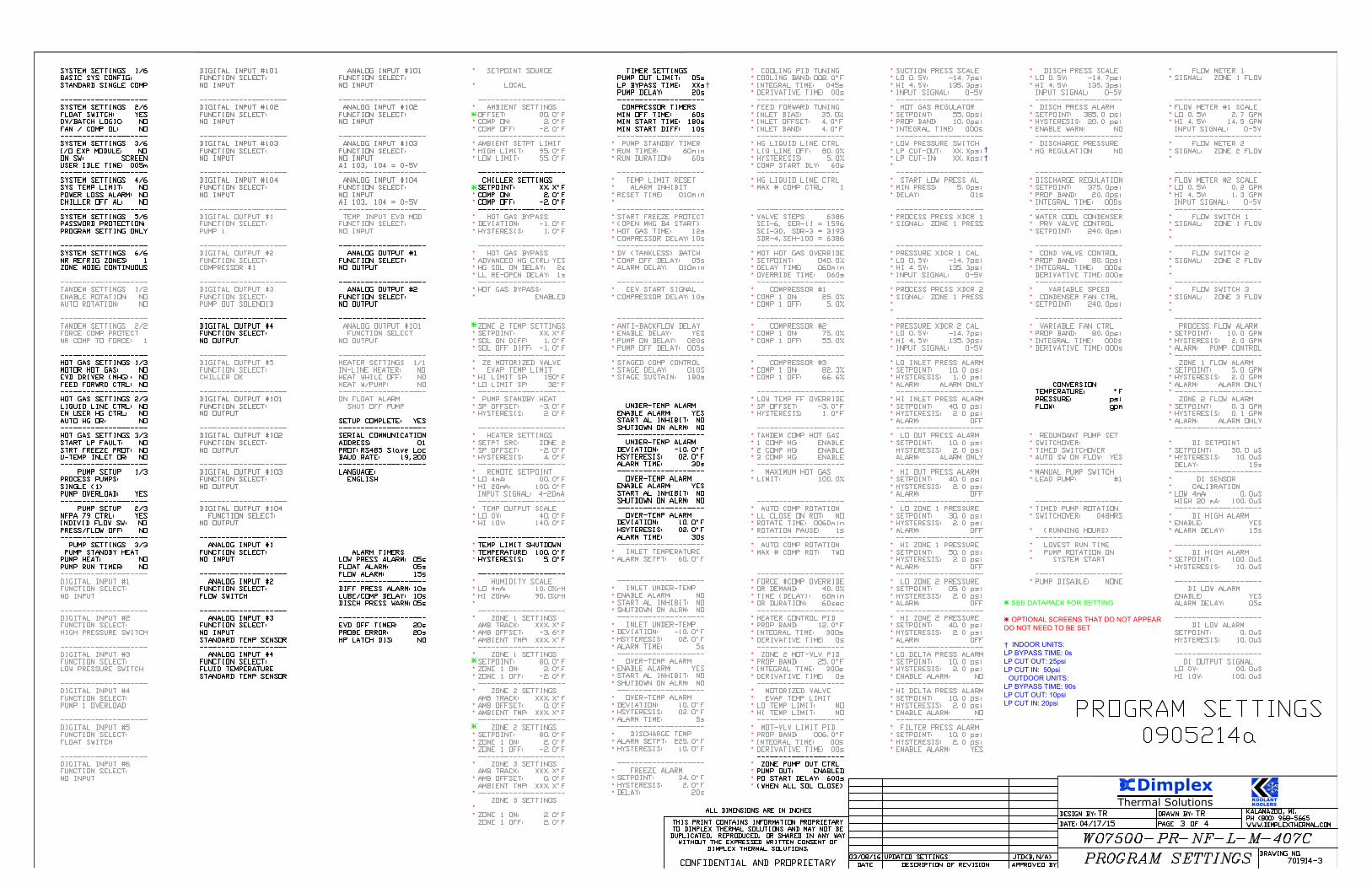
SEE DATAPACK FOR SETTING
OPTIONAL SCREENS THAT DO NOT APPEAR
DO NOT NEED TO BE SET
† INDOOR UNITS:
LP BYPASS TIME: 0s
LP CUT OUT: 25psi
LP CUT IN: 50psi
OUTDOOR UNITS:
LP BYPASS TIME: 90s
LP CUT OUT: 10psi
LP CUT IN: 20psi
†
†
AutoCAD SHX Text
KALAMAZOO, MI. PH (800) 968-5665 WWW.DIMPLEXTHERMAL.COM
AutoCAD SHX Text
DRAWING NO.
AutoCAD SHX Text
DESIGN BY:
AutoCAD SHX Text
DATE:
AutoCAD SHX Text
PAGE
AutoCAD SHX Text
DRAWN BY:
AutoCAD SHX Text
OF
AutoCAD SHX Text
DESCRIPTION OF REVISION
AutoCAD SHX Text
DATE
AutoCAD SHX Text
APPROVED BY
AutoCAD SHX Text
ALL DIMENSIONS ARE IN INCHES
AutoCAD SHX Text
THIS PRINT CONTAINS INFORMATION PROPRIETARY TO DIMPLEX THERMAL SOLUTIONS AND MAY NOT BE DUPLICATED, REPRODUCED, OR SHARED IN ANY WAY WITHOUT THE EXPRESSED WRITTEN CONSENT OF DIMPLEX THERMAL SOLUTIONS. CONFIDENTIAL AND PROPRIETARY
AutoCAD SHX Text
TR
AutoCAD SHX Text
TR
AutoCAD SHX Text
3
AutoCAD SHX Text
4
AutoCAD SHX Text
04/17/15
AutoCAD SHX Text
701914-3
AutoCAD SHX Text
WO7500-PR-NF-L-M-407C
AutoCAD SHX Text
PROGRAM SETTINGS
AutoCAD SHX Text
03/08/16
AutoCAD SHX Text
UPDATED SETTINGS
AutoCAD SHX Text
JTD<B,N/A>
AutoCAD SHX Text
PROGRAM SETTINGS 0905214a
AutoCAD SHX Text
SYSTEM SETTINGS 1/6 BASIC SYS CONFIG: STANDARD SINGLE COMP -------------------- SYSTEM SETTINGS 2/6 FLOAT SWITCH: YES DV/BATCH LOGIC: NO FAN / COMP OL: NO -------------------- SYSTEM SETTINGS 3/6 I/O EXP MODULE: NO ON SW: SCREEN USER IDLE TIME: 005m -------------------- SYSTEM SETTINGS 4/6 SYS TEMP LIMIT: NO POWER LOSS ALARM: NO CHILLER OFF AL: NO -------------------- SYSTEM SETTINGS 5/6 PASSWORD PROTECTION: PROGRAM SETTING ONLY -------------------- SYSTEM SETTINGS 6/6 NR REFRIG ZONES: 1 ZONE MODE:CONTINUOUS -------------------- TANDEM SETTINGS 1/2 ENABLE ROTATION: NO AUTO ROTATION: NO -------------------- TANDEM SETTINGS 2/2 FORCE COMP PROTECT NR COMP TO FORCE: 1 -------------------- HOT GAS SETTINGS 1/3 MOTOR HOT GAS: NO EVD DRIVER (MHG): NO FEED FORWRD CTRL: NO -------------------- HOT GAS SETTINGS 2/3 LIQUID LINE CTRL: NO EN USER HG CTRL: NO AUTO HG OR: NO -------------------- HOT GAS SETTINGS 3/3 START LP FAULT: NO STRT FREEZE PROT: NO U-TEMP INLET OR: NO -------------------- PUMP SETUP 1/3 PROCESS PUMPS: SINGLE (1) PUMP OVERLOAD: YES -------------------- PUMP SETUP 2/3 NFPA 79 CTRL: YES INDIVID FLOW SW: NO PRESS/FLOW OFF: NO -------------------- PUMP SETTINGS 3/3 PUMP STANDBY HEAT PUMP HEAT: NO PUMP RUN TIMER: NO -------------------- DIGITAL INPUT #1 FUNCTION SELECT: NO INPUT -------------------- DIGITAL INPUT #2 FUNCTION SELECT: HIGH PRESSURE SWITCH -------------------- DIGITAL INPUT #3 FUNCTION SELECT: LOW PRESSURE SWITCH -------------------- DIGITAL INPUT #4 FUNCTION SELECT: PUMP 1 OVERLOAD -------------------- DIGITAL INPUT #5 FUNCTION SELECT: FLOAT SWITCH -------------------- DIGITAL INPUT #6 FUNCTION SELECT: NO INPUT
AutoCAD SHX Text
ANALOG INPUT #101 ANALOG INPUT #101 FUNCTION SELECT: NO INPUT -------------------- ANALOG INPUT #102 FUNCTION SELECT: NO INPUT -------------------- ANALOG INPUT #103 FUNCTION SELECT: NO INPUT AI 103, 104 = 0-5V -------------------- ANALOG INPUT #104 FUNCTION SELECT: NO INPUT AI 103, 104 = 0-5V -------------------- TEMP INPUT EVD MOD FUNCTION SELECT: NO INPUT -------------------- ANALOG OUTPUT #1 FUNCTION SELECT: NO OUTPUT -------------------- ANALOG OUTPUT #2 FUNCTION SELECT: NO OUTPUT -------------------- ANALOG OUTPUT #101 ANALOG OUTPUT #101 FUNCTION SELECT NO OUTPUT -------------------- HEATER SETTINGS 1/1 IN-LINE HEATER: NO HEAT WHILE OFF: NO HEAT W/PUMP: NO -------------------- ON FLOAT ALARM SHUT OFF PUMP SETUP COMPLETE: YES -------------------- SERIAL COMMUNICATION ADDRESS: 01 PROT:RS485 Slave Loc BAUD RATE: 19,200 -------------------- LANGUAGE: ENGLISH ALARM TIMERS LOW PRESS ALARM: 05s FLOAT ALARM: 05s FLOW ALARM: 15s -------------------- DIFF PRESS ALARM:10s LUBE/COMP DELAY: 10s DISCH PRESS WARN:05s -------------------- EVD OFF TIMER: 20s PROBE ERROR: 20s HP LATCH DIS: NO NONO
AutoCAD SHX Text
SETPOINT SOURCE SETPOINT SOURCE LOCAL -------------------- AMBIENT SETTINGS OFFSET: 00.0°F COMP ON: 2.0°F COMP OFF: -2.0°F -------------------- AMBIENT SETPT LIMIT HIGH LIMIT: 95.0°F LOW LIMIT: 55.0°F -------------------- CHILLER SETTINGS SETPOINT: XX.X°FCOMP ON: 2.0°F COMP OFF: -2.0°F -------------------- HOT GAS BYPASS DEVIATION: -1.0°F HYSTERESIS: 1.0°F -------------------- HOT GAS BYPASS ADVANCED HG CTRL:YES HG SOL ON DELAY: 2s LL RE-OPEN DELAY: 1s -------------------- HOT GAS BYPASS: ENABLED -------------------- ZONE 2 TEMP SETTINGS SETPOINT: XX.X°F SOL ON DIFF: 1.0°F SOL OFF DIFF: -1.0°F -------------------- Z2 MOTORIZED VALVE EVAP TEMP LIMIT HI LIMIT SP: 150°FLO LIMIT SP: 32°F-------------------- PUMP STANDBY HEAT SP OFFSET: -3.0°F HYSTERESIS: 2.0°F -------------------- HEATER SETTINGS SETPT SRC: ZONE 2 SP OFFSET: -2.0°F HYSTERESIS: 4.0°F -------------------- REMOTE SETPOINT LO 4mA: 00.0°F HI 20mA: 100.0°F INPUT SIGNAL: 4-20mA -------------------- TEMP OUTPUT SCALE LO 0V: 40.0°F HI 10V: 140.0°F -------------------- TEMP LIMIT SHUTDOWN TEMPERATURE: 100.0°F HYSTERESIS: 5.0°F -------------------- HUMIDITY SCALE LO 4mA: 10.0%rH HI 20mA: 90.0%rH -------------------- ZONE 1 SETTINGS AMB TRACK: XXX.X°FAMB OFFSET: -3.6°FAMBIENT TMP: XXX.X°F-------------------- ZONE 1 SETTINGS SETPOINT: 80.0°FZONE 1 ON: 2.0°FZONE 1 OFF: -2.0°F-------------------- ZONE 2 SETTINGS AMB TRACK: XXX.X°FAMB OFFSET: 0.0°FAMBIENT TMP: XXX.X°F-------------------- ZONE 2 SETTINGS SETPOINT: 80.0°FZONE 1 ON: 2.0°FZONE 1 OFF: -2.0°F-------------------- ZONE 3 SETTINGS AMB TRACK: XXX.X°FAMB OFFSET: 0.0°FAMBIENT TMP: XXX.X°F-------------------- ZONE 3 SETTINGS ZONE 1 ON: 2.0°FZONE 1 OFF: 2.0°F
AutoCAD SHX Text
COOLING PID TUNING COOLING BAND:008.0°FINTEGRAL TIME: 045s DERIVATIVE TIME: 00s -------------------- FEED FORWARD TUNING INLET BIAS: 35.0% INLET OFFSET: 4.0°FINLET BAND: 4.0°F-------------------- HG LIQUID LINE CTRL LIQ LINE OFF: 80.0% HYSTERESIS: 5.0% COMP START DLY: 60s ------------------- HG LIQUID LINE CTRL MAX # COMP CTRL: 1 -------------------- VALVE STEPS 6386 SEI-6, SER-11 = 1596 SEI-30, SDR-3 = 3193 SDR-4,SEH-100 = 6386 -------------------- MOT HOT GAS OVERRIDE SETPOINT: 040.0% DELAY TIME: 060min OVERRIDE TIME: 060s -------------------- COMPRESSOR #1 COMP 1 ON: 25.0% COMP 1 OFF: 5.0% -------------------- COMPRESSOR #2 COMP 1 ON: 75.0% COMP 1 OFF: 55.0% -------------------- COMPRESSOR #3 COMP 1 ON: 82.3% COMP 1 OFF: 66.6% -------------------- LOW TEMP FF OVERRIDE SP OFFSET: -3.0°FHYSTERESIS: 1.0°F-------------------- TANDEM COMP HOT GAS 1 COMP HG: ENABLE 2 COMP HG: ENABLE 3 COMP HG: ENABLE -------------------- MAXIMUM HOT GAS LIMIT: 100.0% -------------------- AUTO COMP ROTATION LL CLOSE ON ROT: NO ROTATE TIME: 0060min ROTATION PAUSE: 1s -------------------- AUTO COMP ROTATION MAX # COMP ROT: TWO -------------------- FORCE #COMP OVERRIDE OR DEMAND: 40.0% TIME (DELAY): 60min OR DURATION: 60sec -------------------- HEATER CONTROL PID PROP BAND: 12.0°FINTEGRAL TIME: 300s DERIVATIVE TIME: 0s -------------------- ZONE 2 MOT-VLV PID PROP BAND: 25.0°FINTEGRAL TIME: 300s DERIVATIVE TIME: 0s -------------------- MOTORIZED VALVE EVAP TEMP LIMIT LO TEMP LIMIT: NO HI TEMP LIMIT: NO -------------------- MOT-VLV LIMIT PID PROP BAND: 006.0°FINTEGRAL TIME: 00s DERIVATIVE TIME: 00s -------------------- ZONE PUMP OUT CTRL PUMP OUT: ENABLED PO START DELAY: 600s (WHEN ALL SOL CLOSE)
AutoCAD SHX Text
SUCTION PRESS SCALE LO 0.5V: -14.7psi HI 4.5V: 135.3psi INPUT SIGNAL: 0-5V -------------------- HOT GAS REGULATOR SETPOINT: 55.0psi PROP BAND: 10.0psi INTEGRAL TIME: 000s -------------------- LOW PRESSURE SWITCH LP CUT-OUT: XX.Xpsi LP CUT-IN: XX.Xpsi -------------------- START LOW PRESS AL MIN PRESS: 5.0psi DELAY: 01s -------------------- PROCESS PRESS XDCR 1 SIGNAL: ZONE 1 PRESS -------------------- PRESSURE XDCR 1 CAL LO 0.5V: -14.7psi HI 4.5V: 135.3psi INPUT SIGNAL: 0-5V -------------------- PROCESS PRESS XDCR 2 SIGNAL: ZONE 1 PRESS -------------------- PRESSURE XDCR 2 CAL LO 0.5V: -14.7psi HI 4.5V: 135.3psi INPUT SIGNAL: 0-5V -------------------- LO INLET PRESS ALARM SETPOINT: 10.0 psi HYSTERESIS: 1.0 psi ALARM: ALARM ONLY -------------------- HI INLET PRESS ALARM SETPOINT: 40.0 psi HYSTERESIS: 2.0 psi ALARM: OFF -------------------- LO OUT PRESS ALARM SETPOINT: 10.0 psi HYSTERESIS: 2.0 psi ALARM: ALARM ONLY -------------------- HI OUT PRESS ALARM SETPOINT: 40.0 psi HYSTERESIS: 2.0 psi ALARM: OFF -------------------- LO ZONE 1 PRESSURE SETPOINT: 30.0 psi HYSTERESIS: 2.0 psi ALARM: OFF -------------------- HI ZONE 1 PRESSURE SETPOINT: 50.0 psi HYSTERESIS: 2.0 psi ALARM: OFF -------------------- LO ZONE 2 PRESSURE SETPOINT: 05.0 psi HYSTERESIS: 2.0 psi ALARM: OFF -------------------- HI ZONE 2 PRESSURE SETPOINT: 40.0 psi HYSTERESIS: 2.0 psi ALARM: OFF -------------------- LO DELTA PRESS ALARM SETPOINT: 10.0 psi HYSTERESIS: 2.0 psi ENABLE ALARM: NO -------------------- HI DELTA PRESS ALARM SETPOINT: 10.0 psi HYSTERESIS: 2.0 psi ENABLE ALARM: NO -------------------- FILTER PRESS ALARM SETPOINT: 10.0 psi HYSTERESIS: 2.0 psi ENABLE ALARM: YES
AutoCAD SHX Text
DIGITAL INPUT #101 FUNCTION SELECT: NO INPUT -------------------- DIGITAL INPUT #102 FUNCTION SELECT: NO INPUT -------------------- DIGITAL INPUT #103 FUNCTION SELECT: NO INPUT -------------------- DIGITAL INPUT #104 FUNCTION SELECT: NO INPUT -------------------- DIGITAL OUTPUT #1 FUNCTION SELECT: PUMP 1 -------------------- DIGITAL OUTPUT #2 FUNCTION SELECT: COMPRESSOR #1 -------------------- DIGITAL OUTPUT #3 FUNCTION SELECT: PUMP OUT SOLENOID -------------------- DIGITAL OUTPUT #4 FUNCTION SELECT: NO OUTPUT -------------------- DIGITAL OUTPUT #5 FUNCTION SELECT: CHILLER OK -------------------- DIGITAL OUTPUT #101 FUNCTION SELECT: NO OUTPUT -------------------- DIGITAL OUTPUT #102 FUNCTION SELECT: NO OUTPUT -------------------- DIGITAL OUTPUT #103 FUNCTION SELECT: NO OUTPUT -------------------- DIGITAL OUTPUT #104 FUNCTION SELECT: NO OUTPUT -------------------- ANALOG INPUT #1 FUNCTION SELECT: NO INPUT -------------------- ANALOG INPUT #2 FUNCTION SELECT: FLOW SWITCH -------------------- ANALOG INPUT #3 FUNCTION SELECT: NO INPUT STANDARD TEMP SENSOR -------------------- ANALOG INPUT #4 FUNCTION SELECT: FLUID TEMPERATURE STANDARD TEMP SENSOR
AutoCAD SHX Text
FLOW METER 1 SIGNAL: ZONE 1 FLOW -------------------- FLOW METER #1 SCALE LO 0.5V: 2.7 GPM HI 4.5V: 14.5 GPM INPUT SIGNAL: 0-5V -------------------- FLOW METER 2 SIGNAL: ZONE 2 FLOW -------------------- FLOW METER #2 SCALE LO 0.5V: 0.2 GPM HI 4.5V: 1.3 GPM INPUT SIGNAL: 0-5V -------------------- FLOW SWITCH 1 SIGNAL: ZONE 1 FLOW -------------------- FLOW SWITCH 2 SIGNAL: ZONE 2 FLOW -------------------- FLOW SWITCH 3 SIGNAL: ZONE 3 FLOW -------------------- PROCESS FLOW ALARM SETPOINT: 10.0 GPM HYSTERESIS: 2.0 GPM ALARM: PUMP CONTROL -------------------- ZONE 1 FLOW ALARM SETPOINT: 5.0 GPM HYSTERESIS: 2.0 GPM ALARM: ALARM ONLY -------------------- ZONE 2 FLOW ALARM SETPOINT: 0.3 GPM HYSTERESIS: 0.1 GPM ALARM: ALARM ONLY -------------------- DI SETPOINT SETPOINT: 50.0 uS HYSTERESIS: 10.0uS DELAY: 15s -------------------- DI SENSOR CALIBRATION LOW 4mA: 0.0uS HIGH 20 mA: 100.0uS -------------------- DI HIGH ALARM ENABLE: YES ALARM DELAY: 15s -------------------- DI HIGH ALARM SETPOINT: 100.0uS HYSTERESIS: 10.0uS -------------------- DI LOW ALARM ENABLE: YES ALARM DELAY: 05s -------------------- DI LOW ALARM SETPOINT: 0.0uS HYSTERESIS: 10.0uS -------------------- DI OUTPUT SIGNAL LO 0V: 00.0uS HI 10V: 100.0uS
AutoCAD SHX Text
DISCH PRESS SCALE LO 0.5V: -14.7psi HI 4.5V: 135.3psi INPUT SIGNAL: 0-5V -------------------- DISCH PRESS ALARM SETPOINT: 385.0 psi HYSTERESIS: 20.0 psi ENABLE WARN: NO -------------------- DISCHARGE PRESSURE HG REGULATION NO -------------------- DISCHARGE REGULATION SETPOINT: 375.0psi PROP BAND: 20.0psi INTEGRAL TIME: 000s -------------------- WATER COOL CONDENSER PRV VALVE CONTROL SETPOINT: 240.0psi -------------------- COND VALVE CONTROL PROP BAND: 80.0psi INTEGRAL TIME: 000s DERIVATIVE TIME:000s -------------------- VARIABLE SPEED CONDENSER FAN CTRL SETPOINT: 240.0psi -------------------- VARIABLE FAN CTRL PROP BAND: 80.0psi INTEGRAL TIME: 000s DERIVATIVE TIME:000s CONVERSION TEMPERATURE: °FPRESSURE: psi FLOW: gpm REDUNDANT PUMP SET SWITCHOVER: TIMED SWITCHOVER AUTO SW ON FLOW: YES -------------------- MANUAL PUMP SWITCH LEAD PUMP: #1 -------------------- TIMED PUMP ROTATION SWITCHOVER: 048HRS (RUNNING HOURS) -------------------- LOWEST RUN TIME PUMP ROTATION ON SYSTEM START -------------------- PUMP DISABLE: NONE
AutoCAD SHX Text
TIMER SETTINGS PUMP OUT LIMIT: 05s LP BYPASS TIME: XXs PUMP DELAY: 20s -------------------- COMPRESSOR TIMERS MIN OFF TIME: 60s MIN START TIME: 180s MIN START DIFF: 10s -------------------- PUMP STANDBY TIMER RUN TIMER: 60min RUN DURATION: 60s -------------------- TEMP LIMIT RESET ALARM INHIBIT RESET TIME: 010min -------------------- START FREEZE PROTECT (OPEN MHG B4 START) HOT GAS TIME: 12s COMPRESSOR DELAY:10s -------------------- DV (TANKLESS) BATCH COMP OFF DELAY: 05s ALARM DELAY: 010min -------------------- EEV START SIGNAL COMPRESSOR DELAY:10s -------------------- ANTI-BACKFLOW DELAY ENABLE DELAY: YES PUMP ON DELAY: 020s PUMP OFF DELAY: 005s -------------------- STAGED COMP CONTROL STAGE DELAY: 010S STAGE SUSTAIN: 180s
AutoCAD SHX Text
UNDER-TEMP ALARM ENABLE ALARM: YES START AL INHIBIT: NO SHUTDOWN ON ALRM: NO -------------------- UNDER-TEMP ALARM DEVIATION: -10.0°FHSYTERESIS: 02.0°FALARM TIME: 30s -------------------- OVER-TEMP ALARM ENABLE ALARM: YES START AL INHIBIT: NO SHUTDOWN ON ALRM: NO -------------------- OVER-TEMP ALARM DEVIATION: 10.0°FHSYTERESIS: 02.0°FALARM TIME: 30s -------------------- INLET TEMPERATURE ALARM SETPT: 60.0°F-------------------- INLET UNDER-TEMP ENABLE ALARM: NO START AL INHIBIT: NO SHUTDOWN ON ALRM: NO -------------------- INLET UNDER-TEMP DEVIATION: -10.0°FHSYTERESIS: 02.0°FALARM TIME: 5s -------------------- OVER-TEMP ALARM ENABLE ALARM: YES START AL INHIBIT: NO SHUTDOWN ON ALRM: NO -------------------- OVER-TEMP ALARM DEVIATION: 10.0°FHSYTERESIS: 02.0°FALARM TIME: 5s -------------------- DISCHARGE TEMP ALARM SETPT: 225.0°FHYSTERESIS: 10.0°F-------------------- FREEZE ALARM SETPOINT: 34.0°FHYSTERESIS: 2.0°FDELAY: 20s
AutoCAD SHX Text
* SEE DATAPACK FOR SETTING * OPTIONAL SCREENS THAT DO NOT APPEAR
AutoCAD SHX Text
*
AutoCAD SHX Text
*
AutoCAD SHX Text
*
AutoCAD SHX Text
*
AutoCAD SHX Text
*