Module-2 Unit 4 Transmission electron microscopy (TEM)
14
Module-2 Unit 4 Transmission electron microscopy (TEM): TEM is also known as conventional transmission electron microscopy or CTEM. Max Knoll and Ernst Ruska invented in 1933 in Berlin. Recent electron microscopy (based on transmission) commonly contains a beam column which is around 2.5m tall and has a 30cm diameter, and they its ability to attain a 2Å resolution. This method is utilized for analysing the surface structure i.e. morphology, surface imperfection i.e. defects, crystal structure of the atom, size of the particle and also samples composition. Design of TEM similar to a light microscope- Fig 1: Similarity of a transmission electron microscope with a wide field light microscope. Working Principle- An extremely thinnest sample is required for scanning in this method from which electron beam is passed through rendering its interaction with the sample as a result of which image is produced. Thus, this so formed image can be magnified and focused on the device used for an imaging, like a fluorescent screen, on a photographic film layer, or to be identified by a sensor like a CCD camera. Instrumentation of TEM- Source of electron
Transcript of Module-2 Unit 4 Transmission electron microscopy (TEM)

Module-2 Unit 4
Transmission electron microscopy (TEM):
TEM is also known as conventional transmission electron microscopy or CTEM.
Max Knoll and Ernst Ruska invented in 1933 in Berlin.
Recent electron microscopy (based on transmission) commonly contains a beam column which is
around 2.5m tall and has a 30cm diameter, and they its ability to attain a 2Å resolution.
This method is utilized for analysing the surface structure i.e. morphology, surface imperfection
i.e. defects, crystal structure of the atom, size of the particle and also samples composition.
Design of TEM similar to a light microscope-
Fig 1: Similarity of a transmission electron microscope with a wide field light microscope.
Working Principle-
An extremely thinnest sample is required for scanning in this method from which electron beam is passed
through rendering its interaction with the sample as a result of which image is produced. Thus, this so
formed image can be magnified and focused on the device used for an imaging, like a fluorescent screen,
on a photographic film layer, or to be identified by a sensor like a CCD camera.
Instrumentation of TEM-
Source of electron

Gun based on Thermionic Emission
Beam of Electron
Electromagnetic lenses
Vacuum chamber
Two Condensers lenses, objective and intermediate lens
Sample holder and stage
(Imaging Device) Phosphor or fluorescent screen
Computer
Fig 1: Instrumentation of TEM
Electron Gun:
Electrons can either be produced by thermionic emission or in a process called cold field emission.
During thermionic emission, a very fine tip of a tungsten filament, a LaB6 crystal or a ZrO/W Schottky
emitter is heated by an electrical current flowing through the electron source enabling the escape of
electrons. The electrons leaving the filament have a low energy and, therefore, need to be accelerated to
the desired speed before entering the electron column. A high voltage between the electron source
(cathode) and an anode plate is applied leading to an electrostatic field through which the electrons are
guided and accelerated. During cold field emission, the electrons can escape from an extremely fine
tungsten tip without heating (room temperature). The advantage of cold field emission sources is the very
high yield of electrons and the very low chromatic aberration of the electrons allowing imaging at atomic
resolution. These instruments are very costly and require particularly high vacuum.

The Electron gun working can be controlled based on 3 parameters:
The accelerating voltage,
Current of the filament (and therfore its temperature),
And the Wehnelt cap bias voltage.
The temperature of the filament tip is controlled by the filament current which in turn controls the
amount of emitted electrons. The filament current is increased till the emitted electron no longer
increases, which actually means that filament is saturated in order to maximize the emission.
The passing current amongst the system of high voltage as well as earth is controlled by bias resistor
setting which in turn is controlled by the gun bias. On small bias voltage when the wehnelt negative
potential is compared to the filament is ineffective which means the electrons that are accelerated in
anode direction is relatively with slight focusing. The beam is consequently spread and appears weak
on the screen. When the biasing is increased then the focusing action is improved therefore the
effective beam brightness is also increased; but, beyond a certain value the Wehnelt is so negative in
comparison to the filament that the brightness starts to decrease because electrons are not permitted to
emit from the filament or, in a case they are emitted so they are repelled back in the direction of the
filament.
The point on which the finest brightness of the beam is attained is determined by the distance
amongst the Wehnelt and the filament.
Electromagnetic lenses:
Electromagnetic lenses consist of a huge bundle of windings of insulated copper wire, a soft iron cast
and pole piece (figure 2A). A magnetic field is induced by the current in the winding and reaches its
main strength at the pole piece of the lens. The accelerated electrons entering the magnetic field are
deviated following the law of a charge passing a magnetic field. The direction of both magnetic field
as well as electrons defines the resultant force which is always perpendicular to the plane. In
conclusion, the electrons take a circular path through the lens system (figure 2B).
Fig 2: Electromagnetic lens. A) The magnetic field is strongest in the area of the pole piece; B)
Electrons passing the magnetic field are deviated perpendicular to the plane defined by the magnetic
field B and the velocity vector v.

Condenser lens system:
The beam diameter isreduced and controlled by the action of condenser lens system. The purpose of
the first condenser C1 lens (or spot size) which is a strong lens is to de-magnify the electron source
image by means of around X1/100 to provide a small “point” source at the “crossover” that is more
coherent than the large (50 μm diameter) tip of the filament. The purpose of the second condenser C2
lens (brightness or intensity) which is a weaker lens is to project the de-magnified image of the source
on top of the sample by a magnification of X2, giving an overall demagnification of X1/50.
Illumination scatter onto the screen is controlled by this lens. A part named condenser aperture is
positioned just below or sometimes amongst the condenser lenses; its role is to collimate (i.e. making
parallel) the beam of the electron as well as modification in its intensity.
Objective and intermediate lenses:
The reason behind the back focal plane being very close to the lens itself is because the magnification
factor of the objective lens is larger. Aperture of the objective (it’s the middle aperture on the column)
is mounted in the back-focal plane. Inside the first image plane beneath the sample selected area
aperture is placed, that is underneath both the objective lens and the objective aperture.
By altering the first projector lens excitation (also known as intermediate lens or diffraction lens),
either an image or a diffraction pattern is produced.
Fig 3: Diagram showing either image or diffraction pattern formation.
Specimen holders and stages:

In TEM, the electron column does not offer a lot of space for the sample. Additionally, the sample should
be fine (thin) so that the electrons can penetrate the specimen and form an image. The average thickness
of a biological specimen should be around 70 nm for a TEM with an acceleration voltage for the electrons
of ~100 kV (the higher the voltage, the thicker specimens can be examined). Thin sections of the
specimen are mounted on copper grids of 3 mm diameter, which are available in a wide variety of
materials and mesh sizes. The grids with the sections on top are attached in a holder and introduced into
the goniometer of the TEM through a vacuum lock, since the system always stays under high vacuum.
The goniometer is the mechanical setup which enables highly precise and stable control of the specimen
holder during imaging. Any drift or instability results in an un-sharp image, in particular at high
magnifications (figure 4).
Fig 4: Thin sections of a specimen on a TEM grid, holder tip and complete specimen holder, which is
introduced into the goniometer of the TEM through a vacuum lock.
Vacuum System:
Vacuum system is employed in electron microscopes for 4 reasons:
As scattering of electrons is easy therefore electrons free mean path at atmospheric pressure is
only around 1cm; however, at 10-6 Pa they can move around 6.5m.
The purpose of the vacuum system is to provide insulation amongst the filament of both anode
and cathode as well as in the region around the field emitters, thus hampering undesirable
electron gun electrical discharge.
In order to inhibit the oxidation and ‘burning out’ of the filament, oxygen is eliminated around
the filament.
Samples contamination is decreased by reducing the interaction amongst beam of the electron
and molecules of the gas.

Fig 5: Example of a vacuum system for a TEM. RP-rotary pump, TMP-turbo molecular pump, IGP-ion
getter pump, ODF-oil diffusion pump.
Various microscope parts are differently vacuumed as per their requirements. The gun requirement is 10-9
Pa vacuum, while the specimen requires 10-6 Pa and the projection chamber plus camera requires 10-5 Pa.
Vacuums can be categorized as: rough (100 - 0.1 Pa), low (10-1 - 10-4 Pa), high (10-4 - 10-7 Pa), or
ultrahigh (< 10-7 Pa).
Phosphor or fluorescent screen (Imaging Device):
There are 2 procedures for specimen observation in TEM as shown in fig.3.
1. Image mode
2. Diffraction mode
In case of image mode, the electron beam hitting the sample is controlled by condenser lens and aperture,
the beam which is transmitted will be focused and enlarged by objective and projector lens thus the image
is formed on the screen, with identifiable information in relation to the microstructure of the sample. In
case of diffraction mode, at the fluorescent screen a diffraction pattern (of electron) is attained which has
originated from the electron beam illuminated sample region. The pattern of diffraction is completely
equal to that of a pattern of X−ray diffraction. The spot pattern is produced by a single crystal on the
screen whereas poly-crystal produces a pattern of powder or ring. The purpose of the image mode is to
analyse microstructure, e.g. the grain size, and lattice defects, whereas the use of diffraction mode is to
examine crystalline structure.
Image Modes of TEM-
In TEM, the 2 primary image modes vary in a style based on a technique an objective aperture is utilized
as a filter in electron optics system are
1. Bright field microscopy

2. Dark field microscopy
Fig 6: Two image modes of TEM
In bright field imaging, the image formed of a thin sample is by the electrons that permit through the film
deprived of diffraction, the diaphragm is used to stop the diffracted electrons. In the corresponding dark
field imaging mode, the image is formed by a diffracted beam. The technique is called as bright Field
which is mainly sensitive to extended crystal lattice defects in an otherwise ordered crystal, such as
dislocations. The electron rays corresponding to bright field and dark field imaging are shown in fig.6.
Electron interaction with matter-
The interaction between the electron beam and the sample is coulombic. The negatively charged electrons
can interact strongly with the electron cloud in the solid and also the positively charged nucleus. In
contrast x-rays are EM radiation and they only interact with the electron cloud. In TEM, for imaging
purposes, only the forward scattered electrons are of interest. There are two main types of scattered
radiation:
Elastic - this represents coherent scattering (mainly) with no loss of energy. There is also a phase
relation with the incident radiation.
Inelastic - the energy of the scattered electrons is lower than the incident beam. These are also
incoherent radiation with no phase relation with the incident radiation.
TEM sample preparation-
Significant part of TEM is its sample preparation for the analysis. There are two main conditions for TEM
sample preparation:

Electron transparent sample must be used. If not the whole sample at least the ROI should be thin.
The allowed thickness value for the metallic samples is 30 - 50 nm. Usually, 100 nm is an upper
limit for the sample thickness.
The sample ought to be mechanically strong for treatment.
TEM samples are either self-supported or mounted on a grid for analysis. Copper grids are the most
commonly used, though for high temperature work Mo grids are used. For nanoparticles and thin films a-
C film is used as support. A-C has low contrast in the TEM and will not obscure the contrast arising from
the specimen. Some typical TEM grids are shown in figure 7.
Fig 7: Typical TEM grids
Thinning the sample by different techniques-
Electrolytic polishing:
Electrolytic polishing is used for conducting samples like metals/alloys in order to produce samples that
are electron transparent. The initially sheet thickness can be around a few hundred μm. This can be
prepared by rolling or grinding bulk specimens. Similarly, metal coatings on substrates can be peeled off
and used for the final thinning. Thin discs can also be cut from bulk specimens. This process is called
coring. These discs are thinned by electrolytic polishing. Electrolytic polishing technique is the window
technique.
The sample is made the anode and a thin stainless sheet is made the cathode. The sample is immersed in
the electrolyte, which is usually cooled by water or liquid nitrogen. Perchloric acid is usually used as the
electrolyte. The sample edges are covered by lacquer to expose a 'window', hence the name. The
experimental setup and the hole generation are shown in figure 8.

Fig 8: Window polishing technique.
When a current is applied the material is dissolved from the anode (sample) and deposits on the cathode.
The rate of dissolution depends on the current and applied voltage. The I - V characteristics are shown in
figure 9. Depending on the current and voltage, there are three regimes - etching, polishing, and pitting.
The edges are coated so that material removal will start within the window. Once a hole is formed within
the window the sample is pulled out. The region around the hole is usually electron transparent and can be
mounted on a TEM grid.
Fig 9: I - V characteristics during polishing.
Ion milling technique:
For non-conducting samples usually grinding and polishing steps are used in order to reduce sample
thickness. Some an ultramicrotome is used in order to generate thin samples. These can be either electron
transparent or can be used as the starting material for further thinning. The schematic of the technique is
shown in Fig 10. For samples, where ultramicrotome cannot be used then a standard tripod polisher is
used in order to thin the sample. This produces samples that are a few nm thick. The final polishing step
is done by an ion beam miller.

Fig 10: Schematic of ultramicrotome technique.
fig 11: The schematic of the ion beam miller and an actual instrument
The sample is bombarded by high energy ions or neutral atoms. Usually Ar ions are used and they are
formed by passing the Ar gas though a high voltage (4 - 6 keV ). The sample is held in vacuum and also
usually cooled by liquid nitrogen. The ions are incident on the sample and sputter material away. To
minimize ion penetration the beam is usually incident at a low angle (≈ 20°) though if the angle is very
small the sputter rate is small. Ion beam is highly controlled and a localized process but it is time
consuming. Sputter rates are usually a few A° per second so that creating an electron transparent sample
can take hours, especially if the initial thickness is high.
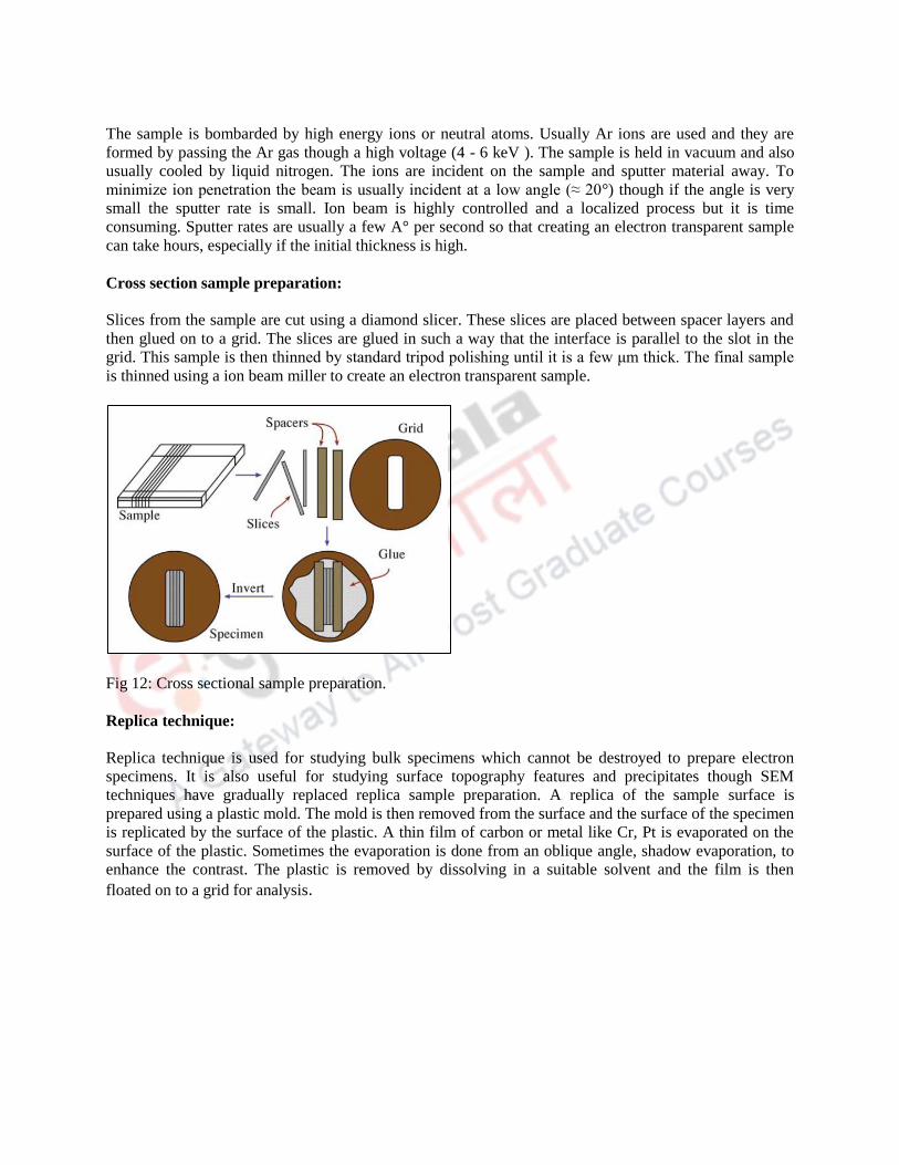
Cross section sample preparation:
Slices from the sample are cut using a diamond slicer. These slices are placed between spacer layers and
then glued on to a grid. The slices are glued in such a way that the interface is parallel to the slot in the
grid. This sample is then thinned by standard tripod polishing until it is a few μm thick. The final sample
is thinned using a ion beam miller to create an electron transparent sample.
Fig 12: Cross sectional sample preparation.
Replica technique:
Replica technique is used for studying bulk specimens which cannot be destroyed to prepare electron
specimens. It is also useful for studying surface topography features and precipitates though SEM
techniques have gradually replaced replica sample preparation. A replica of the sample surface is
prepared using a plastic mold. The mold is then removed from the surface and the surface of the specimen
is replicated by the surface of the plastic. A thin film of carbon or metal like Cr, Pt is evaporated on the
surface of the plastic. Sometimes the evaporation is done from an oblique angle, shadow evaporation, to
enhance the contrast. The plastic is removed by dissolving in a suitable solvent and the film is then
floated on to a grid for analysis.

Fig 13: Replica technique for sample preparation.
References
1) coen.boisestate.edu/faculty-staff/files/2012/01/TEM.pdf
2) Physical Principles of Electron Microscopy, Ray F. Egerton, Springer Verlag, 2007.
3) Griffith G. (1993). Fine Structure Immunocytochemistry. New York, Berlin, Heidelberg. Springer
Verlag. ISBN0-387-54805-X.
4) Electron microscopy methods and protocols / ed. by M.A. Nasser Hajibagheri. - Totowa, N.J. :
Humana Press, cop. 1999. (Methods in molecular biology ; vol. 117)
5) Electron microscopy : methods and protocols. - 2nd ed. / ed. by John Kuo - Totowa, N.J. :
Humana Press, 2007. (Methods in molecular biology ; 369)
6) Electron microscopy : principles and techniques for biologists / John J. Bozzola, Lonnie D.
Russell. - Boston : Jones and Bartlett, 1991. (The Jones and Bartlett series in biology)
7) Introduction to electron microscopy, Andres Kaech, April 2013.
Review your learning
1) Why are thin sections of specimens necessary in TEM?
a) Electrons are negatively charged
b) Electrons have a wave nature
c) Electrons have no mass
d) Electrons have a poor penetrating power.
2) Why TEM images have much higher resolution than images from light microscope?
a) TEM is much greater in size than light microscope
b) Electrons travelling as waves have wavelength much shorter than visible light
c) TEM can achieve greater magnification
d) The fluorescent screen of TEM can generate high resolution images
3) Which of the following is the correct pathway of electrons in the TEM?
a) Anode → electromagnetic lens system → sample → fluorescent screen
b) Anode → electromagnetic lens system → sample → electromagnetic lens system →
fluorescent screen
c) Cathode → electromagnetic lens system → sample → electromagnetic lens system →
fluorescent screen
d) Cathode → electromagnetic lens system → sample → fluorescent screen

4) What should be done right after the TEM column is shown to be evacuated?
a) Insert the sample holder
b) Further insert the sample holder
c) Remove the dummy holder
d) Shift the beam
5) Before loading the sample, the following softwares have to be turned on, except…
a) Electron gun tilt/shift
b) TEM imaging and analysis
c) Microscope user interface
d) Digital Micrograph
True/False:
1) Ultra-violet light is applied to the sample to warm up the sample.
2) The main purpose of cutting extremely thin slices of samples is for better observation of
intracellular components instead of extracellular components.
3) TEM cannot be used to examine live specimen.
4) We should turn off the light before examination of sample using the fluorescent screen.
5) We need to do the alignment of the electron gun, beam and rotation center every time we use the
TEM
Fill in the Blanks:
1) The gun requires the vacuum of the order of …………….
2) The specimen requires the vacuum of the order of …………..
3) Projection chamber and camera requires the vacuum of the order of ……
Long type questions:
1) Explain the working principle of TEM
2) Describe various types of pumps used to achieve vacuum?