Mission and vision of the Department - Jawaharlal Nehru ...jnec.org/Lab-manuals/MECh/ROBO...
37
Mission and vision of the Department Vision of Mechanical Department To establish the state of the art learning center in Mechanical Engineering which will impart global competence, enterprising skills, professional attitude and human values in the student. Mission of Mechanical Department 1. To impart quality technical education to the students. 2. To develop comprehensive competence in the students through various modes of learning. 3. To enable students for higher studies and competitive examinations. 4. To facilitate students and industry professionals for continuous improvement and innovation. Program Educational Objectives: [1] Use core competence acquired in various areas of Mechanical Engineering to solve techno- managerial issues for creating innovative products that lead to better livelihoods & economy of resources. [2] To establish themselves as effective collaborators and innovators to address technical, managerial and social challenges. [3]To equip students for their professional development through lifelong learning and career advancement along with organizational growth. [4] Serve as a driving force for proactive change in industry, society and nation. PROGRAM SPECIFIC OUTCOMES Student should have 1) An ability to work professionally in mechanical systems including design, analysis, production, measurement and quality control. 2) An ability to work on diverse disciplinary tasks including manufacturing, materials, thermal, automobile, robotics, mechatronics, engineering software tools, automation and computational fluid dynamics.
Transcript of Mission and vision of the Department - Jawaharlal Nehru ...jnec.org/Lab-manuals/MECh/ROBO...

Mission and vision of the Department
Vision of Mechanical Department
To establish the state of the art learning center in Mechanical Engineering which will impart global
competence, enterprising skills, professional attitude and human values in the student.
Mission of Mechanical Department
1. To impart quality technical education to the students.
2. To develop comprehensive competence in the students through various modes of
learning.
3. To enable students for higher studies and competitive examinations.
4. To facilitate students and industry professionals for continuous improvement and
innovation.
Program Educational Objectives:
[1] Use core competence acquired in various areas of Mechanical Engineering to solve techno-
managerial issues for creating innovative products that lead to better livelihoods & economy of
resources.
[2] To establish themselves as effective collaborators and innovators to address technical, managerial
and social challenges.
[3]To equip students for their professional development through lifelong learning and career
advancement along with organizational growth.
[4] Serve as a driving force for proactive change in industry, society and nation.
PROGRAM SPECIFIC OUTCOMES
Student should have
1) An ability to work professionally in mechanical systems including design, analysis,
production, measurement and quality control.
2) An ability to work on diverse disciplinary tasks including manufacturing, materials,
thermal, automobile, robotics, mechatronics, engineering software tools, automation and
computational fluid dynamics.
Jawaharlal Nehru Engineering College
Laboratory Manual
ROBOTICS & INDUSTRIAL APPLICATIONS
For
Final year Students of
Mechanical/Production Engineering
02,Dec 2003- rev 00 – Comp Sc – ISO 9000 Tech Document
Author JNEC, Aurangabad
LAB MANUAL OF ROBOTICS AND INDUSTRIAL APPLICATIONS
SUBJECT: ROBOTICS AND INDUSTRIAL APPLICATIONS PRACTICAL: 2 Hrs/Week.
CLASS: BE (MECH. /PROD) TERM WORK: 50 MARKS.
LIST OF EXPERIMENTS:
(1) ASSIGNMENT ON INTRODUCTION TO ROBOT CONFIGURATION
(2) DEMONSTRATION OF ROBOT WITH 2 DOF, 3 DOF, 4 DOF etc.
(3) TWO ASSIGNMENTS ON PROGRAMMING THE ROBOT FOR APPLICATIONS
(4) TWO ASSIGNMENTS ON PROGRAMMING THE ROBOT FOR APPLICATIONS IN
VAL II
(5) TWO PROGRAMMING EXERCISES FOR ROBOTS
(6) TWO CASE STUDIES OF APPLICATIONS IN INDUSTRY
(7) EXERCISE ON ROBOTIC SIMULATION SOFTWARE
EXPERIMENT NO: 01
ASSIGNMENT ON INTRODUCTION TO ROBOT CONFIGURATION

AIM: To study an introduction to Robot configuration.
THEORY:
(1) Introduction & Definition of Industrial Robots:
“An industrial robot is an automatically controlled, reprogrammable, multipurpose manipulator
programmable in three or more axes.”
The field of industrial robotics may be more practically defined as the study, design and use of
robot systems for manufacturing (a top-level definition relying on the prior definition of robot).
Typical applications of industrial robots include welding, painting, ironing, assembly, pick and
place, palletizing, product inspection, and testing, all accomplished with high endurance, speed,
and precision.
The most commonly used robot configurations for industrial automation include articulated
robots, SCARA robots and gantry robots.
In the context of general robotics, most types of industrial robots would fall into the category of
robot arms.
(2) Robotics and Automation:
Robotics is the science of designing and building robots suitable for real-life applications in
automated manufacturing and other non-manufacturing environments. Robot are the means of
performing multifarious activities for man’s welfare in the most planned and integrated manner,
maintaining their own flexibility to do any work, effecting enhanced productivity, Guaranteeing
quality, assuring reliability and ensuring safety to the workers. When the early man started
settling in villages, they invented many innovative implements and left behind inscriptions to
communicate many of their ideas.
To facilitate the manufacture of products, attempts were made to reduce human and animal
labour, and to employ efficient machines run by exploiting other direct or converted natural
energy sources. Meanwhile, the economic rule of demand and supply became operative. To
produce more goods in a reasonably shorter period of time, the speed of production emerged as a
factor of paramount importance. For the given five-M inputs (Man, machines, materials, money
and motivation), more outputs at faster speed became imperative to raise the level of
productivity. Gradually, the degree of mechanization in real life increased by employing more
machines in place of direct labour. Higher heights of mechanization achieved every century,
decade or year rendered the newer machines indispensable.
Programmable automation uses information technology and numerical engineering to
provide coordination, machine control and communication through computers in the most
effective way.af attempts to bridge the gap between consistency and flexibility.
An example of the Programmable automation technology is the robot. The robot is an
essential component of CAM and CIM technologies. The name robot came from the
Czechoslovakin word Robota which means a worker or a slave doing heavy work. The
protoplasm of modern industrial robots is formed of hydraulics, pneumatics, electrical drives and
silicon chips. Today’s robots are therefore, to a great extent, as smart and intelligent as the robots
conceived in fiction. Present-day industrial robots can work efficiently in both structured and
unstructured environments. So, robots with their sensory capabilities and artificial intelligence
(AI) are more advanced than the conventional and automated machines in all respects.
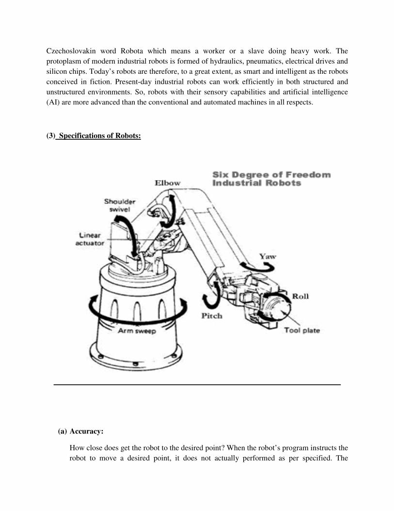
(3) Specifications of Robots:
(a) Accuracy:
How close does get the robot to the desired point? When the robot’s program instructs the
robot to move a desired point, it does not actually performed as per specified. The

accuracy measures such as variance. That is the distance between the specified position
that a robot is trying to achieve (programming point), and the actual x, y, and z resultant
position of the robot end effecter.
(b) Repeatability:
The ability of a robot to return to repeatedly to a given position. It is the ability of the
robotic system or mechanism to repeat the same motion or achieve the same position.
Repeatability is a measure of error or variability when repeatedly reaching for a single
position. Repeatability is often smaller than accuracy.
(c) Degree of Freedom (DOF):
Each joint or axis on the robot introduces a degree of freedom. Each DOF can be a slider,
rotary, or other type of actuator. The number of DOF that a manipulator possesses thus is
the number of independent ways in which a robot arm can move. Industrial robots
typically have 5 or 6 degrees of freedom. 3 of the degrees of freedom allow positioning in
3D space (X, Y, Z), while the other 2 or 3 are used for orientation of the end effector
(yaw, pitch and roll). 6 degrees of freedom are enough to allow the robot to reach all
positions and orientations in 3D space. 5 DOF requires a restriction to 2D space, or else it
limits orientations. 5 DOF robots are commonly used for handling tools such as arc
welders.
(d) Resolution:
The smallest increment of motion or distance that can be detected or controlled by the
robotic control system. It is a function of encoder pulses per revolution and drive (e.g.
reduction gear) ratio. And it is dependent on the distance between the tool center point
and the joint axis.
(e) Reach:
The maximum horizontal distance from the center of the robot base to the end of its
wrist.
(f) Maximum Speed:
A robot moving at full extension with all joints moving simultaneously in complimentary
directions at full speed. The maximum speed is the theoretical values which does not
consider under loading condition.
(g) Payload:
The maximum payload is the amount of weight carried by the robot manipulator at
reduced speed while maintaining rated precision. Nominal payload is measured at
maximum speed while maintaining rated precision. These ratings are highly dependent on
the size and shape of the payload due to variation in inertia.
(h) Envelope:
A three-dimensional shape that defines the boundaries that the robot manipulator can
reach; also known as reach envelope.
(i) Maximum envelope:
The envelope that encompasses the maximum designed movements of all robot parts,
including the end effector, workpiece and attachments.
(j) Restricted envelope:
Restricted envelope is that portion of the maximum envelope which a robot is restricted
by limiting devices.
(k) Operating envelope:
The restricted envelope that is used by the robot while performing its programmed
motions.
(4) Basic configurations of Industrial Robots with their applications:
Industrial robots come in a variety of shapes and sizes. They are capable of various
arm manipulations and they possess different motion systems. This section discusses the various basic physical configurations of robots.

The following four basic Configurations can be combined in various ways to produce a variety of robotic combinations.
a) Cartesian Configuration:
Fig: Cartesian Configuration
Cartesian robot is form by 3 prismatic joints, whose axes are coincident with the X, Y and Z
planes.
In the Cartesian coordinate configuration shown in figure, the three orthogonal directions are
X,Y and Z. X-coordinate axis may represent left and right motion; Y- coordinate axis may
describe forward and backward motion; Z-coordinate axis may be used to represent up and
down motions. Motions in any coordinate axis can be imparted independently of the other
two. The manipulator can reach any point in a cubic volume of space. It allows three DOFs
(x, y, z) in translation only.
Advantages:
1) 3 linear axes.
2) Easy to visualize, ability to do straight line insertions into furnaces.
3) Most rigid structure for given length.
4) Easy computation and programming.
Disadvantages:
1) Can only reach front of it.
2) Requires large floor space.
3) Axes hard to seal.

Applications:
Pick and Place operations, Assembly and Sub-Assembly (Mostly Straight), automated loading
CNC Lathe and Milling operations, Nuclear Material handling, Welding etc.
b) Spherical Configuration:
Fig: Spherical Configuration
In the Spherical coordinate configuration shown in figure, the robot has one linear and two
angular motions. The linear motion, r corresponds to a radial in or out translation, the first
angular motion corresponds to a base rotation, and second angular motion ,is one that rotates
about an axis perpendicular to the vertical through the base and is sometimes termed as elbow
rotation. The two rotations along with the in or out motion enable the robot to reach an
specified point in the space bounded by an outer and inner hemisphere. Sometimes, the
spherical coordinate system is referred to as polar coordinate system.
It is still in the research laboratory, the Spherical robot is actually a spherical shape robot,
which has an internal driving source.
Advantages:
1) 1 linear + 2 rotating axes.
2) Large working envelops.
Disadvantages:
1) Can’t reach around obstacles.
2) Low accuracy.
3) Complex coordinates more difficult to visualize, control, and program.

Applications:
Die Casting, Dip Coating, Forging, Glass Handling, Heat Treating, Injection Moulding,
Machine Tool Handling, Material Transfer, Parts cleaning, Press Loading etc.
c) Cylindrical Configuration:
Fig: Cylindrical Configuration
Cylindrical robot is able to rotate along his main axes forming a cylindrical shape.
In the cylindrical coordinate configuration shown in figure, Consists of a vertical column,
relative to which an arm assembly is moved up or down. The arm can be moved in or out relative
to the column. A cylindrical robot has a two orthogonal prismatic axes of movement (horizontal
and vertical) and one revolute axis, forming a cylindrical coordinate system. It is capable of
higher horizontal plane speeds vs. cartesian systems due the revolute base. However horizontal,
straight line motion is more complex to calculate and tends to be slower. The resolution of the
positioning of the end effector is not constant, but depends on the degree of extension along the
horizontal axis. If a monomast construction is used for the horizontal element, clearance behind
the robot must be accounted for when retracted
Advantages:
1) 2 linear axes +1 rotating.
2) Can reach all around itself.
3) Reach and height axes rigid.
4) Rotational axis easy to seal.
5) Relatively easy programming.
Disadvantages:
1) Can’t reach above itself.
2) Base rotation axis as less rigid.
3) Linear axes are hard to seal.
4) Won’t reach around obstacles.
Applications:
Assembly, Coating Applications, Conveyor Pallet Transfer, Die Casting, Forging Applications,
Inspection Moulding, Investment Casting, Machine Loading and Unloading etc.
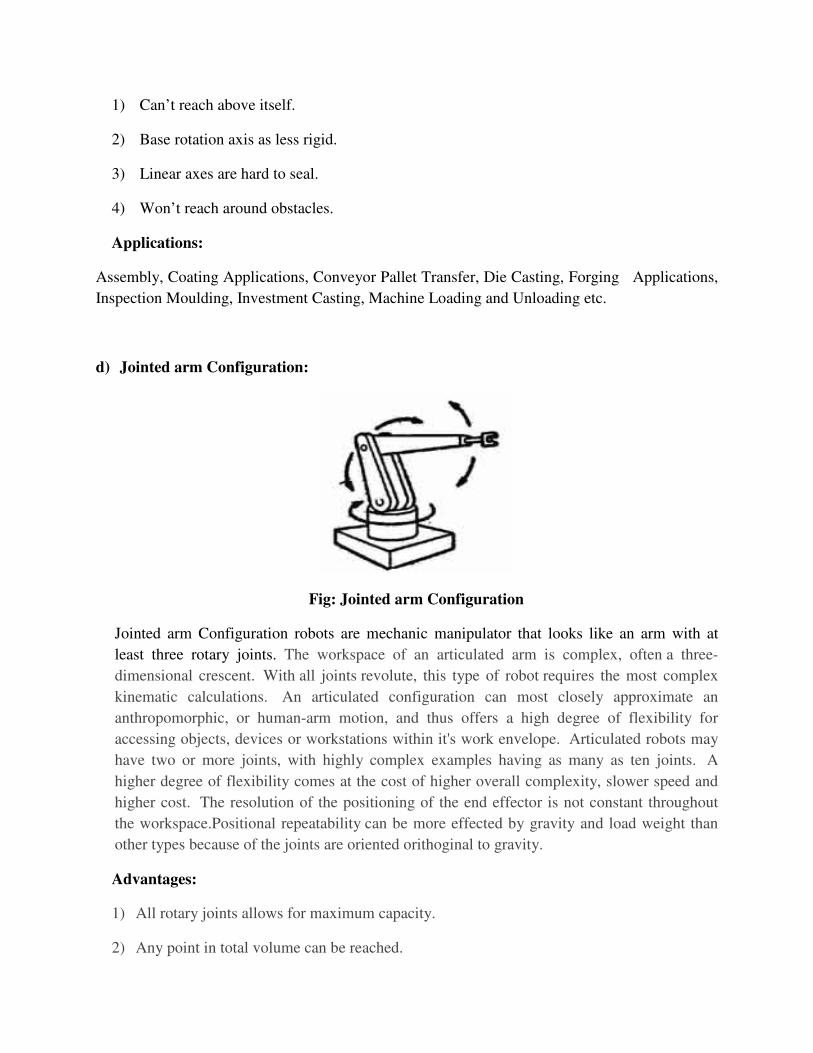
d) Jointed arm Configuration:
Fig: Jointed arm Configuration
Jointed arm Configuration robots are mechanic manipulator that looks like an arm with at
least three rotary joints. The workspace of an articulated arm is complex, often a three-
dimensional crescent. With all joints revolute, this type of robot requires the most complex
kinematic calculations. An articulated configuration can most closely approximate an
anthropomorphic, or human-arm motion, and thus offers a high degree of flexibility for
accessing objects, devices or workstations within it's work envelope. Articulated robots may
have two or more joints, with highly complex examples having as many as ten joints. A
higher degree of flexibility comes at the cost of higher overall complexity, slower speed and
higher cost. The resolution of the positioning of the end effector is not constant throughout
the workspace.Positional repeatability can be more effected by gravity and load weight than
other types because of the joints are oriented orithoginal to gravity.
Advantages:
1) All rotary joints allows for maximum capacity.
2) Any point in total volume can be reached.

3) All joints can be sealed from the environment.
Disadvantages:
1) Extremely difficult to visualize, control, and program.
2) Low accuracy.
Applications:
Assembly operations, Welding, Spray painting, Weld sealing etc.
e) SCARA:
Fig: SCARA
SCARA stands for Selectively Compliant Assembly Robot Arm.
Similar to jointed-arm robot except that vertical axes are used for shoulder and elbow joints to
be compliant in horizontal direction for vertical insertion tasks. It consists of two or more
revolute joints and one prismatic, all of which operate parallel to gravity, easing the mechanical
burden. As the name indicates, this configuration has been designed to offer variable compliance
in horizontal directions, which can be an advantage in assembly tasks. The kinematics of this
configuration are quite complex and the vertical component of movement is generally rather
limited.Thus, it can reach around objects in the workspace, but not over them. The resolution of
the positioning of the end effector is not constant throughout the workspace, but these robots do
have a high degree of positional repeatability. They are generally faster and more expensive than
cartesian systems.
Advantages:
1) 1 linear + 2 rotating axes.
2) Height axis is rigid.

3) High Speed.
4) Large work area for floor space.
5) Moderately easy to program.
Disadvantages:
1) Difficult to program off-line.
2) Highly complex arm.
3) 2 ways to reach point.
4) Limited Applications.
Applications:
Assembly operations, Pick and Place work etc.
CONCLUSION:
Hence, we have studied the Robot Configurations.
EXPERIMENT NO: 02
DEMONSTRATION OF ROBOT WITH 2 DOF, 3 DOF, 4 DOF
AIM: Study of ROBOT With 2DOF,3DOF & 4DOF.


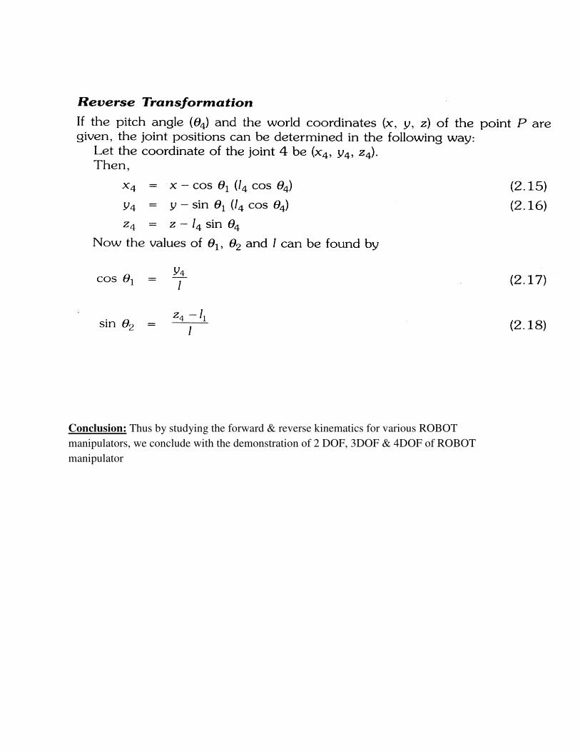
Conclusion: Thus by studying the forward & reverse kinematics for various ROBOT
manipulators, we conclude with the demonstration of 2 DOF, 3DOF & 4DOF of ROBOT
manipulator

EXPERIMENT NO: 03
TWO ASSIGNMENTS ON PROGRAMMING THE ROBOT FOR APPLICATIONS
AIM: To study the Robot programming for industrial applications.
PROGRAM 1:
Palletizing application using AL.
Begin ‘Palletizing sample program’
Frame in-pallet, out-pallet, part;
Comment
The (1, 1) positions of the pallets and grasping position of parts;
Vector del-r1, del-c1;
Vector del-r2, del-c2;
COMMENT relatives’ displacements along the rows and columns;
Scalar r1, c1, ir1, ic1;
Scalar r2, c2, ir2, ic2;
COMMENT COUNTERS;
EVENT in-pallet-empty, in-pallet-replaced;
EVENT out-pallet-full, out -pallet-replaced;
COMMENT
Here insert the frame definition for IN-PALLET and OUT-PALLET and the vector value for
displacements along and recorded using robot
PROCEDURE PICK;
BEGIN
FRAME Pick-frame;
Ir1=ir1+1;
IF ir1 c1Tr1

THEN
BEGIN
ir1; =1
ic1; = ic1+1
IF ic1c1Tc1
THEN
BEGIN
SINGAL in-pallet-empty;
WAIT in-pallet-replaced;
ic1; =1;
END;
END;
Pick-frame; = in-pallet+ (ir1-1)*del-r1+( ic1-1)*del-c1
MOVE BEHIND TO PICK FRAME;
CENTRE BARM;
AFFIX PART TO BARM;
END
PROCEDURE PLACE
BEGIN
FRAME PLACE-frame
ir2; = ir2+1
IF ir2c1Tr2
THEN
BEGIN
ir2; = 1;

ic2; = ic2+1
IF ic2c1Tc2
THEN
BEGIN
SINGAL OUT-Pallet-empty;
WAIT OUT-Pallet-replaced;
ic2; =1;
END;
END;
Place-frame; out-Pallet+(ir2-1)*del-r2+( ic2-1)*del-r2.
MOVE Part To Place-frame.
OPEN BHAND To 3.0*IN
UNFIX PART FROM BARM;
END;
COMMENT THE main Program,
OPEN BHAND To 3.0*IN;
WHILE TRUE DO
BEGIN
PICK;
PLACE;
END;
END;

PROGRAM 2:
Palletizing application using KAREL
PROGRAM PALLET
---Transfer workpieces from one pallet to another.
---Variables for the input pallet,
BASE 1; position—(1,1) position on pallet.
IR 1, IC 1: integer.
NR1, NC1: integer.
DR 1, DC 1: vector.
1S1G1, 0S1G1; intger.
--Variables for the output pallet.
BASE 2; Position
IR 2, IC 2: integer.
NR2, NC2: integer.
DR 2, DC2: vector.
1S1G2, 0S1G2; intger.
ROUTINE PICK
--Pick a workpiece from the input Pallet.
TARGET: POSITION—targetpose
BEGIN
IR1=IR1+1
If IR1>NR1
Then
I R1=1
IC1=IC1+1

If IC1>NC1
Then,
IC1=1
dout (0S1G1)=true
wait for din (1S1G1) +
dout (0S1G1)=false.
End if
End if
TARGET = BASE1
Shift (TARGET, (1R1-1)*DR1+(1C1-1)*DC1
Move near TARGET by 50
Move to TARGET
Close hand 1
Move away 50
and Pick
ROUTINE PLACE
--Place a workpiece on the output pallet var
TARGET:POSITION.
BEGIN
IR2= IR2+1
If IR2>NR2
Then,
IR2=1
IC2=IC2+1
If IC2>NC2

Then,
IC2=1
dout (0SIG2)=true.
Wait for din (1SIG2)+1
dout (0SIG2)=false.
End if
End if
TARGET=BASE 2
Shift (TARGET, (1R2-1)*DR2+(1C2-1)*DC2
Mover near TARGET by 50
Move to TARGET
Close hand 1
Move away 50
end Place.

MAIN PROBLEM
BEGIN
IR1=0; IC1=0
IR2=0; IC2=0
--initialize other variable
--BASE 1, NR1, NC1, DR1, DC1, IS1G1, 0S1G1.
--BASE 2, NR2, NC2, DR2, DC2, IS1G2, 0S1G2.
--numerical pose definition omitted here.
Opened hand 1
While true do—loop.
PICK
PLACE
and while
and PALLET.
CONCLUSION: Thus, we have studied the Robot programming for industrial applications.

EXPERIMENT NO: 04
ASSIGNMENT ON PROGRAMMING THE ROBOT FOR APPLICATION IN VAL II
AIM: To study the Robot programming application in VAL II.
PROGRAM:
Palletizing application in VAL II
In the VAL II version of Palletizing application, the program transfer parts between two Pallets
using the external binary I/O signals to request additional pallets. It communicates with the user
via the system terminal asking questions and providing information on system operation. A
Pallet location is taught by instructing the operator to move the robot to the corners of pallet. The
program then computes all locations in the pallet.
PROGRAM Main ( )
;
ABSTRACT:- This is the top level program to move
; Thee parts between two Pallets. It allows the operator
; To teach the Pallet locations if desired & then
; moves parts from one pallet to next
; DATA STRUCTURE
; in. Pallet [.]=An array of location for items on the pallet to be unloaded.
; in. height =approach/depart height for input pallet.
; in. max= The no. of items on a full input pallet.
; in. count= The no. of items left on this I/P pallet.
; out. pallet [ ] = An array of location for items on pallet to be loaded,
; out height = approach/dipalt height for O/P pallet.
; out. max= The no. of items on a full O/P pallet.
; out. count= The no. of items left on this O/P pallet
; #Safe=soft robot location reachable from both pallets
LOCAL sans in count, out count
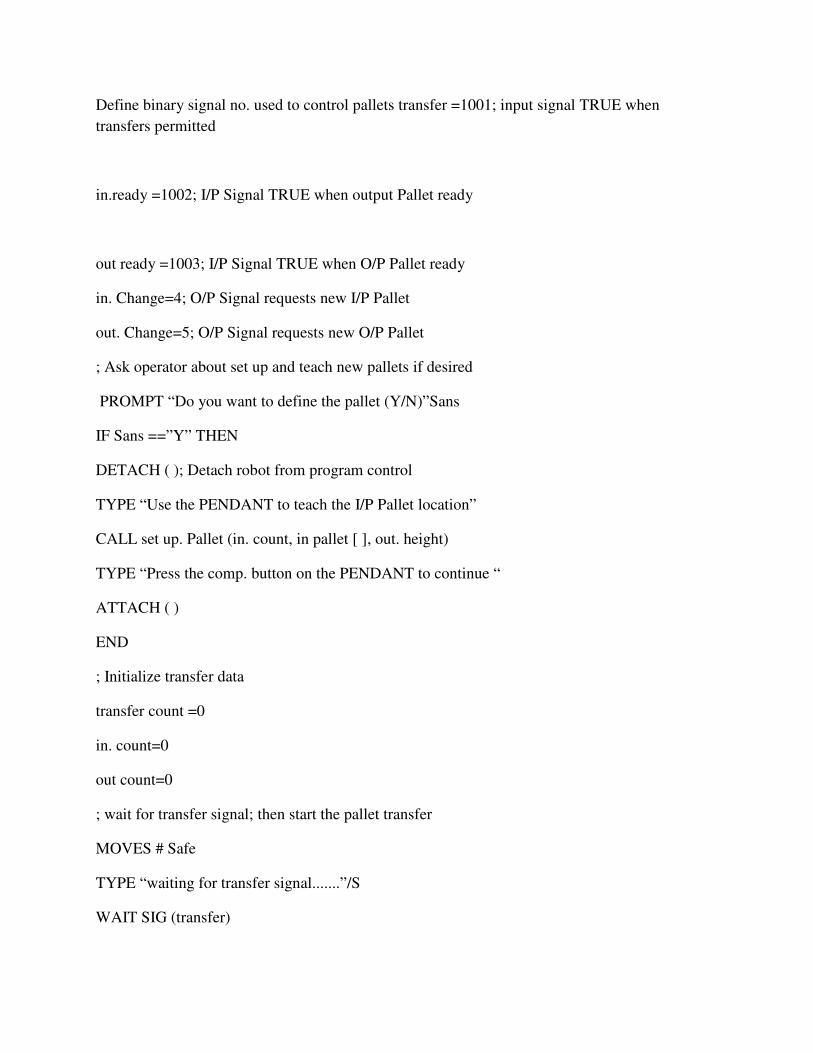
Define binary signal no. used to control pallets transfer =1001; input signal TRUE when
transfers permitted
in.ready =1002; I/P Signal TRUE when output Pallet ready
out ready =1003; I/P Signal TRUE when O/P Pallet ready
in. Change=4; O/P Signal requests new I/P Pallet
out. Change=5; O/P Signal requests new O/P Pallet
; Ask operator about set up and teach new pallets if desired
PROMPT “Do you want to define the pallet (Y/N)”Sans
IF Sans ==”Y” THEN
DETACH ( ); Detach robot from program control
TYPE “Use the PENDANT to teach the I/P Pallet location”
CALL set up. Pallet (in. count, in pallet [ ], out. height)
TYPE “Press the comp. button on the PENDANT to continue “
ATTACH ( )
END
; Initialize transfer data
transfer count =0
in. count=0
out count=0
; wait for transfer signal; then start the pallet transfer
MOVES # Safe
TYPE “waiting for transfer signal.......”/S
WAIT SIG (transfer)
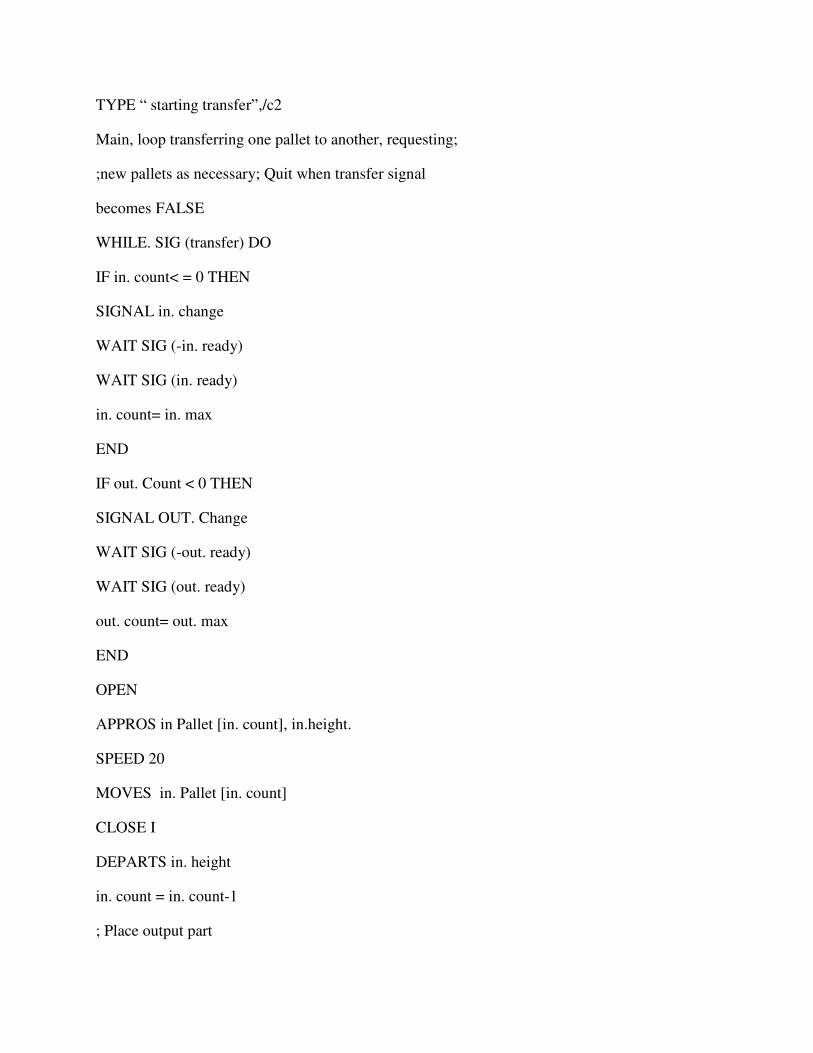
TYPE “ starting transfer”,/c2
Main, loop transferring one pallet to another, requesting;
;new pallets as necessary; Quit when transfer signal
becomes FALSE
WHILE. SIG (transfer) DO
IF in. count< = 0 THEN
SIGNAL in. change
WAIT SIG (-in. ready)
WAIT SIG (in. ready)
in. count= in. max
END
IF out. Count < 0 THEN
SIGNAL OUT. Change
WAIT SIG (-out. ready)
WAIT SIG (out. ready)
out. count= out. max
END
OPEN
APPROS in Pallet [in. count], in.height.
SPEED 20
MOVES in. Pallet [in. count]
CLOSE I
DEPARTS in. height
in. count = in. count-1
; Place output part
APPROS out
SPEED 20
MOVES out. Pallet [out. count]
OPEN I
DEPARTS out. height
out. count = out. count-1
; Count transfer and display it.
transfer. Count = transfer. Count+1
TYPE N, ”Number of parts transferred,” / I8, transfer. count
END;
; All done transferring parts, move robots to safe place and quit
MOVES # Safe
END
PROGRAM set up pallet (count. Array [ ],approach)
; INPUT PARM ; NONE
;
;OUTPUT PARM ; Count = No. of items on their pallet.
array [ ]= Array containing the pallet location
approach = The approach height for their Pallet.
Local r1; 11, 1r, ap, t [], ncol, nrow
Local row, COL.cs, rs, i, frame
Ask operator to teach pallet location
CALL teach. Point (“Upper left pallet location”,Ll)
CALL teach. Point (“Lower left pallet position”, Ll)
CALL teach. Point (“Lower right pallet position”, Lr)
CALL teach. Point (“approach height above pallet”, ap)
PROMPT “Enter the no. of columns (left to right);” ncol
PROMPT “Enter the no. of columns (top to bottom);” nrow
Count = ncol*nrow
; set up to compute pallet location
cs = 0
IF ncol>1 THEN
cs =DISTANCE (ll1lr)/(ncol=1)
END
; Compute frame values
SET frame = FRAME (ll,lr,l1l,l1l)
approach = DZ [ INVERSE (frame);ap]
DECOMPOSE t [1]=l1L
LOOP to compute array value
i =1
For row=0 to nrow-1
For col=0 to ncol-1
SET array [i]= frame.;TRANS ( row*rs, col*cs,0,t[4],t[5],t[6]
i = i+1
END
END
RETURN
END.
CONCLUSION: Thus, we have studied the Robot programming for application in VAL II.

EXPERIMENT NO: 05
TWO PROGRAMMING EXERCISES FOR ROBOTS
AIM: To perform the Robot programming exercise for Pick and Place operation.
THEORY:
Most controllers for industrial robots provide a method of dividing a program into
one or more branches. Branching allows the robot program to be subdivided into convenient
segments that can be executed during the program. A branch can be thought of as a sub routine
that is called one or more times during the program. The subroutine can be executed either by
branching to it at a particular place in the program or by testing an input signal line to branch to
it. The amount of decision logic that can be incorporated into a program varies widely with
controllers. They permit the use of an incoming signal to invoke a branch. Most controllers allow
the user to specify whether the signal should be interrupt the program branch currently being
executed, or wait until the current branch completes. The interrupt capability is typically used for
error branches. An error branch is invoked when an incoming signal indicates that some
abnormal event has occurred. Depending on the event and the design of the error branch, the
robot will either take some corrective action or simply terminate the robot motion and signal for
human assistance.
A frequent use of the branch capability is when the robot has been programmed to
perform more than one task. In this case, separate branches are used for indicating which branch
of the program must be executed and when it must be executed. A common way of
accomplishing this is to mate use of external signals which are activated by sensors or other
interlocks. The device recognizes which took must be performed, and provide the appropriate
signal to all that branch. This method is frequently used or spray painting robot which have been
programmed to paint a limited variety of parts moving post the workstation of a conveyor
photoelectric cells are frequently employed to identify the part of to be sprayed by distinguishing
between the geometric features of different parts. The photoelectric cells are used to generate the
signal to the robot to call the spray painting sub routine corresponding to the particular part.
Robot programs have thus far been discussed as consisting of a series of points in
space, where each point is designed as a set of joint coordinate corresponding to the number of
degree of freedom of robot. These points are specified as in absolute coordinates. That is when
the robot executes program; each point is visited at exactly the same location every time. The
new concept involves the use of a relocatable branch.
A relocated branch allows the programmer to specify a branch involving a set of
internal points in space that are performed relative to some defined starting point for the branch.
This would permit the same motion subroutine to be performed at various locations in the
workspace of the robot. Many industrial robots have the capacity to accept reloadable branches
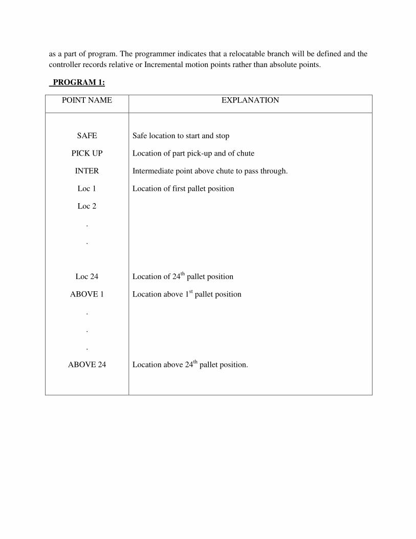
as a part of program. The programmer indicates that a relocatable branch will be defined and the
controller records relative or Incremental motion points rather than absolute points.
PROGRAM 1:
POINT NAME EXPLANATION
SAFE
PICK UP
INTER
Loc 1
Loc 2
.
.
Loc 24
ABOVE 1
.
.
.
ABOVE 24
Safe location to start and stop
Location of part pick-up and of chute
Intermediate point above chute to pass through.
Location of first pallet position
Location of 24th
pallet position
Location above 1st pallet position
Location above 24th
pallet position.

Suppose that the operation required the robot to pick up parts from an input chute and place them
on a pallet with 24 positions. When a start signal is given, the robot must begin picking up parts
and loading them into the pallet, continuing until all 24 positions on the pallet is filled. The robot
must then generate a signal to indicate that the pallet is full, and wait for the start signal to being
the next cycle. When the robot is directed to go to the point name in the program, it goes to the
associated joint coordinates.
In creating robot programs for palletizing operations of this type, the robot is
programmed to approach a given part from a direction choose to avoid interference with the
other parts.
The speed at which the program is executed should be varied during the program when the
gripper is approaching a pick up of drop off point, the speed setting should be at a relatively slow
value. When the robot moves larger distance the chute and the pallet, higher speed would be
programmed.

PROGRAM 2:
Program for Pick and Place activity:
STATEMENT
STATEMENT DESCRIPTION
BRANCH PICK
MOVE INTER
WAIT 12
SIGNAL 5
MOVE PICK-UP
SIGNAL 6
MOVE INTER
END BRANCH
BRANCH PLACE
MOVE Z (-50)
SIGNAL 5
MOVE Z (50)
END BRANCH
The branch of program indicating part picks.
Move to an intermediate position chute.
Wait for an incoming part to chute.
Open gripper fingers (Sensor control)
Move gripper and Pick-up the object.
Close the gripper to grasp the object.
Depart to intermediate position above chute.
End of pick-up activity.
Start of placing activity.
Position part and gripper above the pallet .
Open gripper to release the part.
Depart from the place point.
End of place activity.
CONCLUSION: Thus, we have studied how to perform Pick and Place operation.

EXPERIMENT NO: 06
TWO CASE STUDIES OF APPLICATIONS IN INDUSTRY
(1) Introduction and general considerations in robot applications.
(2) Case study I: Robot application for Welding.
(3) Case study II: Robot application for Spray painting.
EXPERIMENT NO: 07
EXERCISE ON ROBOTIC SIMULATION SOFTWARE
AIM: To study the Robot path planning using Robotic simulation software.
THEORY:
The locus of points along the path defines the sequence of position through which the
robot will move its wrist. In most applications, an end effector is attached to the wrist and
program can be considered to be the path in space through which the end effector is to be moved
by the robot.
Since, the robot consists of several joint (axes) linked together, the definition of the
path in space in effect requires that the robot move its axes through various positions in order to
follow that path for a robot with six axes, each point in the path consists of six coordinates value
corresponds to the position of one joint. There are basic robot anatomies; Polar, Cylindrical,
Cartesian and Jointed Arm.
Each one of three axes associated with the arm and body configuration and two or three
additional joints are associated with wrist. The arm and body joint determines the general
position in space of the end effector and the wrist determines its orientation. If we think of a joint
in space in the robot program as a position and orientation of the end effector, there is usually
more than one possible set of joint coordinate values that can be used for the robot to reach that
point.
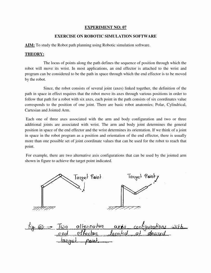
For example, there are two alternative axis configurations that can be used by the jointed arm
shown in figure to achieve the target point indicated.
As shown in figure (a) that; although the target point has been reached by both of alternative axis
configurations, there is a difference in the orientation of the wrist with respect to the point. We
must conclude from this that the specification of the joint coordinates of the robot does define
only one point in a space that corresponds to that set of coordinate values. Point specified in this
fashion are said to be joint coordinates. Accordingly, an advantage of defining robot program in
this way is that is simultaneously specifies the position and orientation of the end effector at each
point in the path.
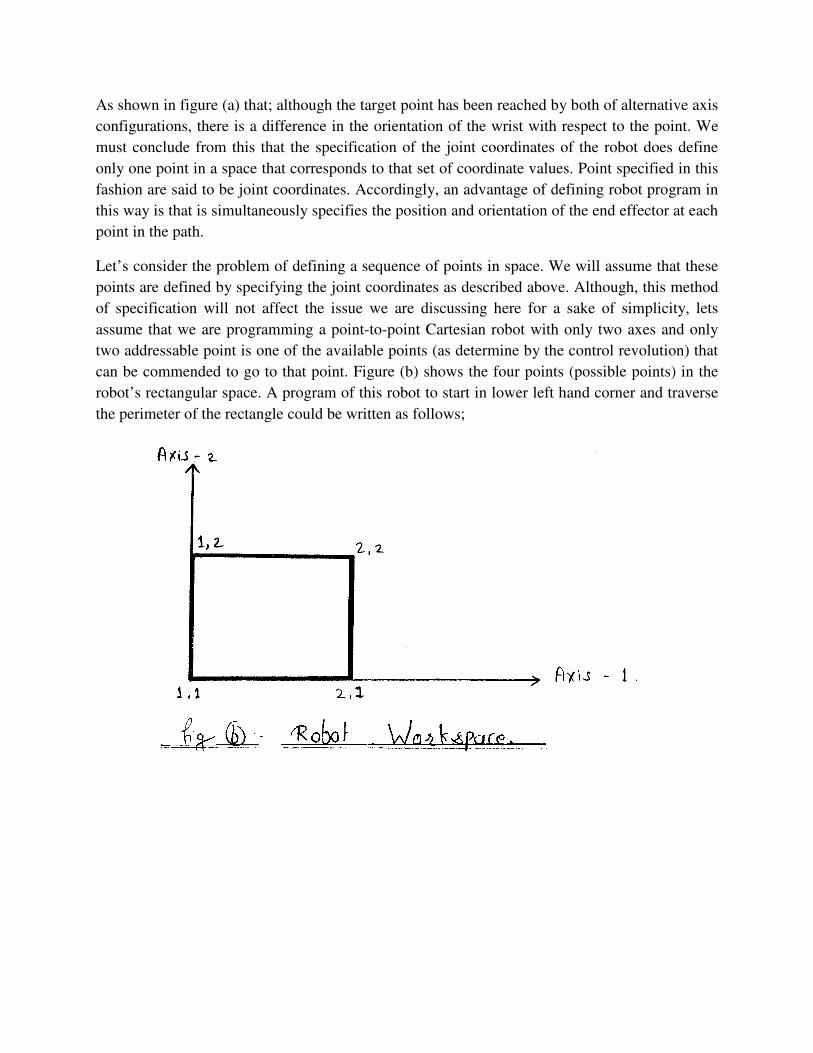
Let’s consider the problem of defining a sequence of points in space. We will assume that these
points are defined by specifying the joint coordinates as described above. Although, this method
of specification will not affect the issue we are discussing here for a sake of simplicity, lets
assume that we are programming a point-to-point Cartesian robot with only two axes and only
two addressable point is one of the available points (as determine by the control revolution) that
can be commended to go to that point. Figure (b) shows the four points (possible points) in the
robot’s rectangular space. A program of this robot to start in lower left hand corner and traverse
the perimeter of the rectangle could be written as follows;

STEP MOVE COMMENTS
1 1, 1 Move to lower left corner.
2 2, 1 Move to lower right corner.
3 2, 2 Move to upper right corner.
4 1, 2 Move to upper left corner.
5 1, 1 Move back to start position.
The point designation corresponds to the x, y- coordinates positions in the Cartesian axis system.
In this example, using a robot with two orthogonal slides and only two addressable points per
axis, the definition of points in space corresponds exactly with joint coordinate’s values.
CONCLUSION: Thus, we have studied the robot path planning using simulation control
software.