
MiniBrute User's Manual - Arturia
49
Arturia MiniBrute User's Manual 1 6 Legal notes USER'S MANUAL
Transcript of MiniBrute User's Manual - Arturia
Arturia MiniBrute User's Manual 1 6 Legal notes
USER'S MANUAL
Arturia MiniBrute User's Manual 2 6 Legal notes
PRODUCT AND PROJECT MANAGEMENT
Frédéric BRUN
Romain DEJOIE
ELECTRONICS
Yves USSON
Bruno PILLET
François BEST
Laurent BARET
Robert BOCQUIER
Antoine BACK
DESIGN
Axel HARTMANN (Design Box)
Daniel VESTER
Morgan PERRIER
INDUSTRIALIZATION
Nicolas DUBOIS
Suzy ZHU (Huaxin)
MANUAL
Yves USSON
Craig ANDERTON
Antoine BACK
Yasu TANAKA
Noritaka UBUKATA
SPECIAL THANKS TO:
Arnaud REBOTINI, Étienne JAUMET, Jean-Benoît DUNCKEL, Simon TARRICONE,
Glen DARCEY, Frank ORLICH, Jean-Michel BLANCHET, Frédéric MESLIN,
Mathieu BRUN, Gérard BURACCHINI.
1st edition: February 2012
Information contained in this manual is subject to change without notice and does not represent a
commitment on behalf of ARTURIA. The hardware unit and the software product described in this manual are
provided under the terms of a license agreement or non-disclosure agreement. The license agreement
specifies the terms and conditions for its lawful use.
No part of this manual may be produced or transmitted in any form or by any purpose other than purchaser’s
personal use, without the explicit written permission of ARTURIA S.A. All other products, logos or company
names quoted in this manual are trademarks or registered trademarks of their respective owners.
© ARTURIA S.A. 1999-2012, all rights reserved.
ARTURIA S.A.
4, chemin de Malacher
38240 Meylan
FRANCE
http://www.arturia.com
Arturia MiniBrute User's Manual 3 6 Legal notes
TABLE OF CONTENTS
1 Introduction ............................................................................. 5
2 Installation ............................................................................... 9 2.1 Usage Precautions ................................................................................................. 9
2.2 Register your Instrument ...................................................................................... 11
2.3 Connecting the MiniBrute to the World ............................................................ 11
2.4 Warm-Up and General Tuning ........................................................................... 12
3 Quickstart .............................................................................. 14 3.1 Create your first sound: the “basic patch” ...................................................... 14
3.2 Add some vibrato ................................................................................................ 15
3.3 Tweak the envelope ............................................................................................ 16
3.4 Meet the LFO ......................................................................................................... 17
3.5 Create arpeggiated sequences ....................................................................... 18
4 General description ............................................................. 20 4.1 Analog synthesizer architecture ........................................................................ 20
4.1.1 Signal generators..................................................................................................................... 20
4.1.1.1 Pitched signal generator (oscillators) ................................................................................. 20
4.1.1.2 Unpitched signal generator ................................................................................................. 21
4.1.2 Signal enhancers ..................................................................................................................... 22
4.1.3 Filter ........................................................................................................................................... 23
4.1.3.1 What is a filter? ........................................................................................................................ 23
4.1.3.2 Filter types: Low-pass, Band-pass, High-pass and Notch ................................................ 23
4.1.3.3 Resonance or emphasis ........................................................................................................ 25
4.1.4 Amplifier .................................................................................................................................... 25
4.1.5 Modulators ............................................................................................................................... 26
4.1.6 Player interface ....................................................................................................................... 27
4.1.7 Inputs and outputs .................................................................................................................. 28
4.1.8 MiniBrute diagram ................................................................................................................... 29
4.2 Front Panel ............................................................................................................. 30 4.2.1 The oscillator and its signal mixer .......................................................................................... 30
4.2.1.1 The waveforms ........................................................................................................................ 30 Saw and Ultrasaw ................................................................................................................................ 30
Square and Modulated Pulse ............................................................................................................ 30
Triangle and Metalizer ......................................................................................................................... 31
The sub-oscillator (Sub Osc) ............................................................................................................... 31
Noise ...................................................................................................................................................... 31
Audio In ................................................................................................................................................. 31
4.2.2 The filter..................................................................................................................................... 32
4.2.2.1 Mode ......................................................................................................................................... 32
4.2.2.2 Cutoff ........................................................................................................................................ 32
4.2.2.3 Resonance ............................................................................................................................... 32
4.2.2.4 ENV Amt (envelope amount) .............................................................................................. 33
4.2.2.5 KBD Tracking ............................................................................................................................ 33
4.2.2.6 Envelope speed ...................................................................................................................... 33
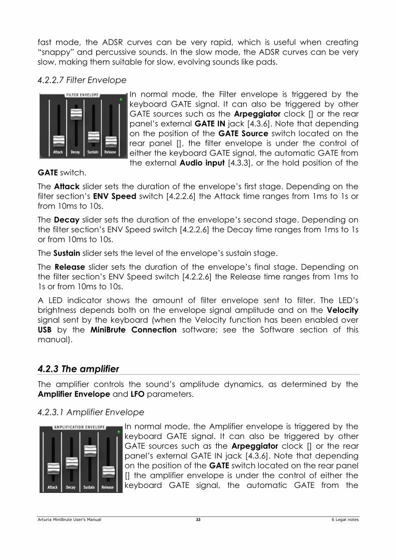
4.2.2.7 Filter Envelope ......................................................................................................................... 33
4.2.3 The amplifier ............................................................................................................................. 34
4.2.3.1 Amplifier Envelope ................................................................................................................. 34
4.2.4 Controls ..................................................................................................................................... 34
4.2.4.1 MOD Wheel ............................................................................................................................. 34
4.2.4.2 Aftertouch ................................................................................................................................ 35
4.2.4.3 Bend Range ............................................................................................................................. 35
Arturia MiniBrute User's Manual 4 6 Legal notes
4.2.4.4 Glide .......................................................................................................................................... 35
4.2.5 Vibrato ...................................................................................................................................... 35
4.2.6 LFO ............................................................................................................................................ 36
4.2.6.1 Wave ......................................................................................................................................... 36
4.2.6.2 Rate ........................................................................................................................................... 36
4.2.6.3 Clock ......................................................................................................................................... 36
4.2.6.4 Modulation routing ................................................................................................................. 36 PWM & Metalizer .................................................................................................................................. 36
Pitch........................................................................................................................................................ 37
Filter ........................................................................................................................................................ 37
Amp ........................................................................................................................................................ 37
4.2.7 Arpeggiator .............................................................................................................................. 37
4.2.7.1 Hold/On/Off ............................................................................................................................. 37
4.2.7.2 Octave ..................................................................................................................................... 38
4.2.7.3 Mode ......................................................................................................................................... 38
4.2.7.4 Swing ......................................................................................................................................... 38
4.2.7.5 Step ........................................................................................................................................... 38
4.2.7.6 Tempo & Tap ........................................................................................................................... 38
4.2.8 General controls ...................................................................................................................... 39
4.2.8.1 Keyboard ................................................................................................................................. 39
4.2.8.2 Wheels ...................................................................................................................................... 40
4.2.8.3 Octave ..................................................................................................................................... 40
4.2.8.4 Brute Factor ............................................................................................................................. 40
4.2.8.5 Phones ...................................................................................................................................... 41
4.2.8.6 Master Volume ........................................................................................................................ 41
4.2.8.7 Fine Tune .................................................................................................................................. 41
4.3 Rear panel ............................................................................................................. 41 4.3.1 Power supply ............................................................................................................................ 41
4.3.2 USB ............................................................................................................................................. 42
4.3.3 MIDI ........................................................................................................................................... 42
4.3.4 Gate Source............................................................................................................................. 42
4.3.5 AUDIO ....................................................................................................................................... 42
4.3.6 CV / GATE IN ............................................................................................................................ 43
4.3.7 CV / GATE OUT ........................................................................................................................ 43
4.4 Configuration software: MiniBrute Connection ............................................... 43
5 Using your MiniBrute ............................................................. 44 5.1 Let's create a basic sound .................................................................................. 44
5.2 Sound modulations .............................................................................................. 46
5.3 External sound processing .................................................................................. 47
6 Legal notes ............................................................................ 48 6.1 No liability for consequential damages ............................................................ 48
6.2 FCC Information (USA) ......................................................................................... 48
6.3 Canada ................................................................................................................ 49
6.4 Europe .................................................................................................................... 49
Arturia MiniBrute User's Manual 5 6 Legal notes
1 INTRODUCTION
Congratulations, and thank you for your purchase of the ARTURIA MiniBrute analog
synthesizer. You now own what many players feel is the best sounding, most
versatile, and most powerful analog synthesizer in its class.
The MiniBrute is the culmination of a lengthy (and very enjoyable!) collaboration
between ARTURIA’s engineers and analog synthesizer “guru” Yves USSON.
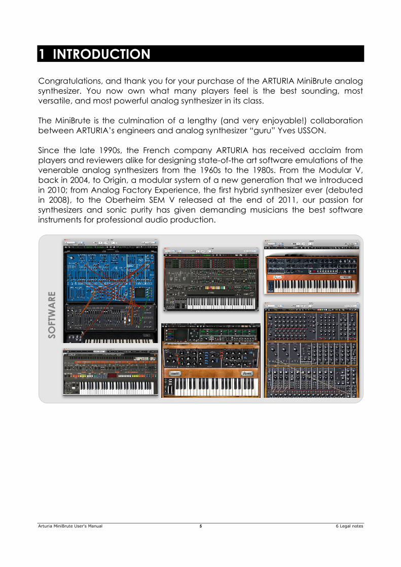
Since the late 1990s, the French company ARTURIA has received acclaim from
players and reviewers alike for designing state-of-the art software emulations of the
venerable analog synthesizers from the 1960s to the 1980s. From the Modular V,
back in 2004, to Origin, a modular system of a new generation that we introduced
in 2010; from Analog Factory Experience, the first hybrid synthesizer ever (debuted
in 2008), to the Oberheim SEM V released at the end of 2011, our passion for
synthesizers and sonic purity has given demanding musicians the best software
instruments for professional audio production.
SO
FTW
AR
E
Arturia MiniBrute User's Manual 6 6 Legal notes
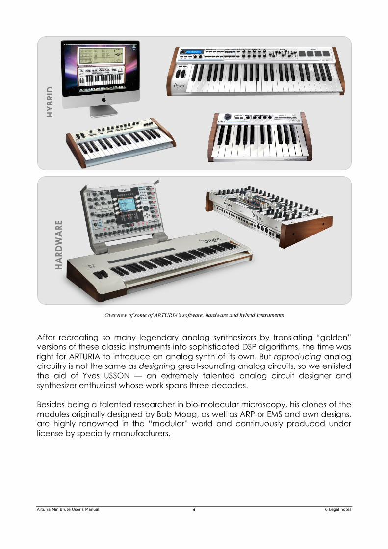
Overview of some of ARTURIA’s software, hardware and hybrid instruments
After recreating so many legendary analog synthesizers by translating “golden”
versions of these classic instruments into sophisticated DSP algorithms, the time was
right for ARTURIA to introduce an analog synth of its own. But reproducing analog
circuitry is not the same as designing great-sounding analog circuits, so we enlisted
the aid of Yves USSON — an extremely talented analog circuit designer and
synthesizer enthusiast whose work spans three decades.
Besides being a talented researcher in bio-molecular microscopy, his clones of the
modules originally designed by Bob Moog, as well as ARP or EMS and own designs,
are highly renowned in the “modular” world and continuously produced under
license by specialty manufacturers.
HY
BR
ID
HA
RD
WA
RE
Arturia MiniBrute User's Manual 7 6 Legal notes
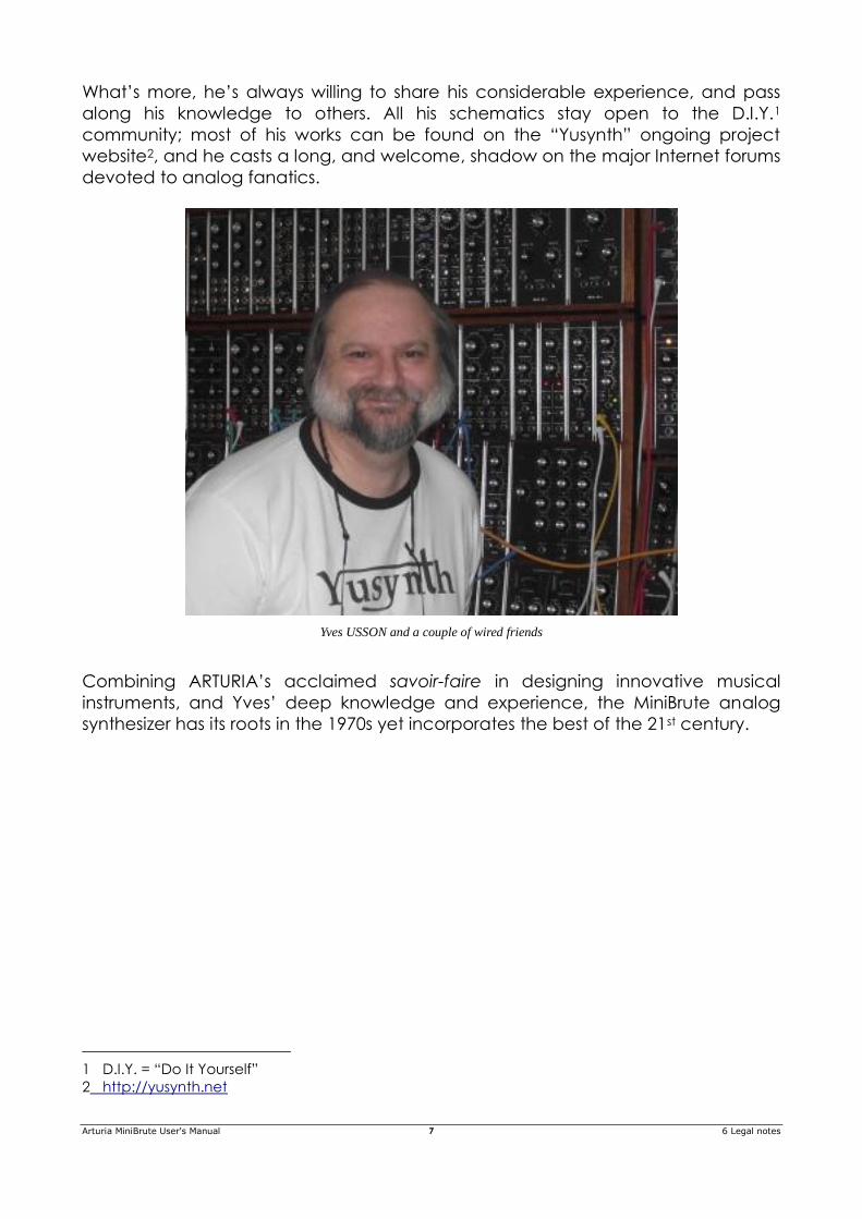
What’s more, he’s always willing to share his considerable experience, and pass
along his knowledge to others. All his schematics stay open to the D.I.Y.1
community; most of his works can be found on the “Yusynth” ongoing project
website2, and he casts a long, and welcome, shadow on the major Internet forums
devoted to analog fanatics.
Yves USSON and a couple of wired friends
Combining ARTURIA’s acclaimed savoir-faire in designing innovative musical
instruments, and Yves’ deep knowledge and experience, the MiniBrute analog
synthesizer has its roots in the 1970s yet incorporates the best of the 21st century.
1 D.I.Y. = “Do It Yourself”
2 http://yusynth.net
Arturia MiniBrute User's Manual 8 6 Legal notes
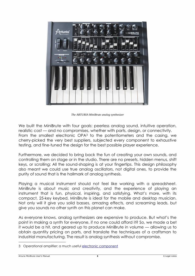
The ARTURIA MiniBrute analog synthesizer
We built the MiniBrute with four goals: peerless analog sound, intuitive operation,
realistic cost — and no compromises, whether with parts, design, or connectivity.
From the smallest electronic OPA3 to the potentiometers and the casing, we
cherry-picked the very best suppliers, subjected every component to exhaustive
testing, and fine-tuned the design for the best possible player experience.
Furthermore, we decided to bring back the fun of creating your own sounds, and
controlling them on stage or in the studio. There are no presets, hidden menus, shift
keys, or scrolling: All the sound-shaping is at your fingertips. This design philosophy
also meant we could use true analog oscillators, not digital ones, to provide the
purity of sound that is the hallmark of analog synthesis.
Playing a musical instrument should not feel like working with a spreadsheet.
MiniBrute is about music and creativity, and the experience of playing an
instrument that is fun, physical, inspiring, and satisfying. What’s more, with its
compact, 25-key keybed, MiniBrute is ideal for the mobile and desktop musician.
Not only will it give you solid basses, amazing effects, and screaming leads, but
give you sounds no other synth on this planet can make.
As everyone knows, analog synthesizers are expensive to produce. But what’s the
point in making a synth for everyone, if no one could afford it? So, we made a bet
it would be a hit, and geared up to produce MiniBrute in volume — allowing us to
obtain quantity pricing on parts, and translate the techniques of a craftsman to
industrial manufacturing. The result is analog synthesis without compromise.
3 Operational amplifier: a much useful electronic component
Arturia MiniBrute User's Manual 9 6 Legal notes
MiniBrute is truly a musical instrument. We loved designing it, building it, and now,
playing it. We hope you will share our enthusiasm, and find inspiration in its sounds.
But that’s enough talk — plug in your new analog friend, and start vibrating the
walls...
Arturia MiniBrute User's Manual 10 6 Legal notes
2 INSTALLATION
2.1 Usage Precautions
The MiniBrute uses an external power adapter. Do not use any power supply or
adapter other than the one provided by Arturia and specified in this manual (see
chapter for more details). ARTURIA accepts no responsibility for damage caused
by use of an unauthorized power supply.
WARNING
Do not place this product in a place or position where one might walk on, trip
over, or roll anything over power cords or connecting cables.
The use of an extension cord is not recommended. However if you must use one,
make sure that the cord has the ability to handle the maximum current needed by
this product. Please consult a local electrician for more information on your power
requirements.
This product should be used only with the components supplied or recommended
by ARTURIA. When used with any components, please observe all safety markings
and instructions that accompany the accessory products.
SPECIFICATIONS SUBJECT TO CHANGE
The information contained in this manual is believed to be correct at the time of
printing. However, ARTURIA reserves the right to change or modify any of the
specifications without notice or obligation to update existing units.
IMPORTANT
Always follow the basic precautions listed below to avoid the possibility of serious
injury or even death from electrical shock, damages, fire or other risks.
The product used either alone or in combination with an amplifier, headphones or
speakers, may be able to produce sound levels that could cause permanent
hearing loss. DO NOT operate for long periods of time at a high level, at a level
that is uncomfortable, or a level that exceeds prevailing safety standards for
hearing exposure. If you encounter any hearing loss or ringing in the ears, consult
an audiologist immediately. It is also a good idea to have you ears and hearing
checked annually.
NOTICE
Arturia MiniBrute User's Manual 11 6 Legal notes
The manufacturer’s warranty does not cover service charges incurred due to a
lack of knowledge relating to how a function or feature works (when the unit is
operating as designed); reading the manual is the owner's responsibility. Please
study this manual carefully and consult your dealer before requesting service.
PRECAUTIONS INCLUDE, BUT ARE NOT LIMITED TO, THE FOLLOWING:
Read and understand all the instructions.
Always follow the instructions on the instrument.
Before cleaning the instrument, always remove the electrical plug from the
outlet, as well as the USB cable. When cleaning, use a soft and dry cloth. Do
not use gasoline, alcohol, acetone, turpentine or any other organic
solutions; do not use liquid cleaner, spray or cloth that’s too wet.
Do not use the instrument near water or moisture, such as a bathtub, sink,
swimming pool or similar place.
Do not place the instrument in an unstable position where it might
accidentally fall over.
Do not place heavy objects on the instrument. Do not block openings or
vents of the instrument; these locations are used for ventilation to prevent
the instrument from overheating. Do not place the instrument near a heat
vent or any place of poor air circulation.
Use only the provided AC adapter, as specified by ARTURIA (see chapter for
more details).
Make sure the line voltage in your location matches the input voltage
specified on the AC power adapter.
Do not open and insert anything into the instrument, as this could cause a
fire or electrical shock.
Do not spill any kind of liquid onto the instrument.
In the event of a malfunction, always take the instrument to a qualified
service center. You will invalidate your warranty if you open and remove the
cover, and improper testing may cause electrical shock or other
malfunctions.
Do not use the instrument when thunder and lightning is present.
Do not expose the instrument to hot sunlight.
Do not use the instrument when there is a gas leak nearby.
ARTURIA is not responsible for any damage or data loss caused by improper
operations to the instrument.
ARTURIA recommends the use of shielded and less than 3 meters long cables
for Audio, and ferrite equipped CV/Gate cables.
Arturia MiniBrute User's Manual 12 6 Legal notes
2.2 Register your Instrument
Registering your instrument establishes your legal ownership, which entitles you to
access the Arturia Technical Support service, and be informed of updates.
Additionally, you can subscribe to the ARTURIA newsletter to be informed of
ARTURIA-related news as well as promotional offers.
Connect to your Arturia account via this URL:
http://www.arturia.com/login
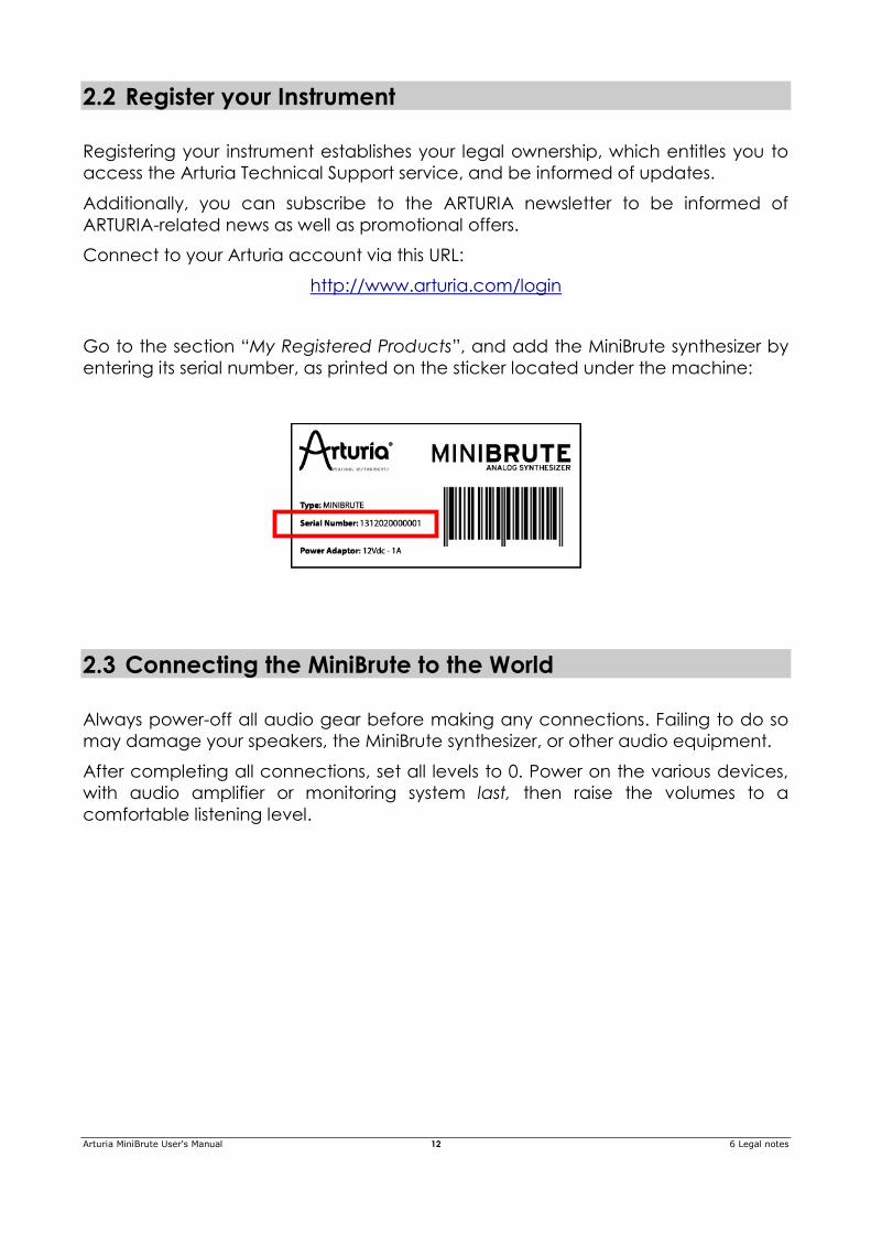
Go to the section “My Registered Products”, and add the MiniBrute synthesizer by
entering its serial number, as printed on the sticker located under the machine:
2.3 Connecting the MiniBrute to the World
Always power-off all audio gear before making any connections. Failing to do so
may damage your speakers, the MiniBrute synthesizer, or other audio equipment.
After completing all connections, set all levels to 0. Power on the various devices,
with audio amplifier or monitoring system last, then raise the volumes to a
comfortable listening level.
Arturia MiniBrute User's Manual 13 6 Legal notes
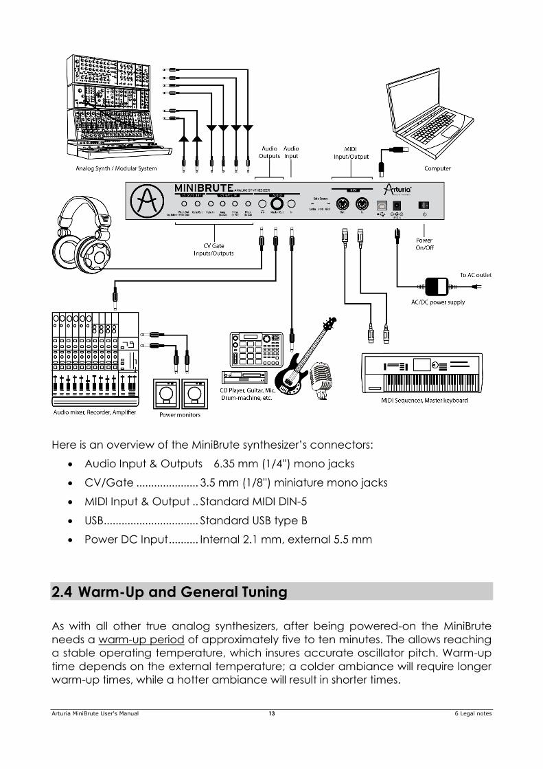
Here is an overview of the MiniBrute synthesizer’s connectors:
Audio Input & Outputs 6.35 mm (1/4'') mono jacks
CV/Gate ..................... 3.5 mm (1/8'') miniature mono jacks
MIDI Input & Output .. Standard MIDI DIN-5
USB................................ Standard USB type B
Power DC Input .......... Internal 2.1 mm, external 5.5 mm
2.4 Warm-Up and General Tuning
As with all other true analog synthesizers, after being powered-on the MiniBrute
needs a warm-up period of approximately five to ten minutes. The allows reaching
a stable operating temperature, which insures accurate oscillator pitch. Warm-up
time depends on the external temperature; a colder ambiance will require longer
warm-up times, while a hotter ambiance will result in shorter times.
Arturia MiniBrute User's Manual 14 6 Legal notes
Once the synthesizer has reached its running temperature, tune it to pitch. Use an
external tuner to check the instrument’s tuning; if needed, tweak the Fine Tune
knob to tune the MiniBrute to the desired pitch.
The MiniBrute has been designed for rock-solid pitch stability when operated in
normal temperature and humidity conditions, at external temperatures between
20°C and 32°C in temperate areas. In practice, the MiniBrute provides satisfactory
operation over a much wider temperature range, although extreme external
temperatures or fluctuations can lead to longer stabilization time or erratic tuning.
Arturia MiniBrute User's Manual 15 6 Legal notes
3 QUICKSTART
This chapter provides the basics you’ll need to create your very first sounds with the
MiniBrute, so you can start enjoying its rich, full sounds immediately. In subsequent
chapters, we’ll get deeper into the sound design process so you can create more
animated and complex sounds.
3.1 Create your first sound: the “basic patch”
Once your MiniBrute has been correctly connected to your sound system, set all
the controls to their minimum level:
counter-clockwise for the knobs
lowest position for sliders
centered position (12 o'clock) for controls with – and +, as well as Fine Tune.
Set the rear panel Gate Source switch to the KBD position (see chapter ).
Set the FILTER section’s Mode switch to LP, and the ENV Speed switch to Fast.
Set the CONTROL section’s Aftertouch switch to Off, and MOD Wheel to Vibrato.
Set the VIBRATO switch to the position.
Set the LFO section’s Clock switch to the Free position.
Set the ARPEGGIATOR section’s Hold/On/Off switch to Off.
Switch on your MiniBrute, let it warm up, and set the Master Volume knob to
center.
Set the MIX section’s square wave slider to maximum.
Turn the FILTER section’s Cutoff knob fully clockwise.
Set the AMPLIFICATION ENVELOPE section’s Sustain slider to maximum.
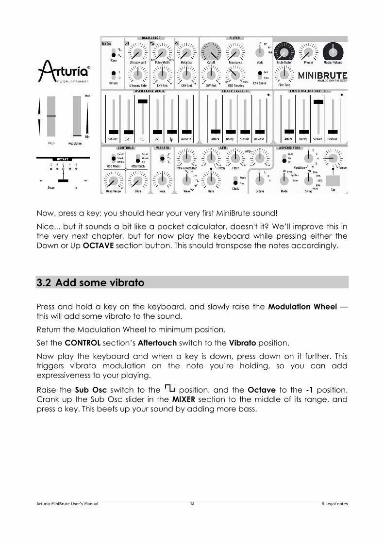
Here’s an overview of the patch:
Arturia MiniBrute User's Manual 16 6 Legal notes
Now, press a key; you should hear your very first MiniBrute sound!
Nice... but it sounds a bit like a pocket calculator, doesn't it? We’ll improve this in
the very next chapter, but for now play the keyboard while pressing either the
Down or Up OCTAVE section button. This should transpose the notes accordingly.
3.2 Add some vibrato
Press and hold a key on the keyboard, and slowly raise the Modulation Wheel —
this will add some vibrato to the sound.
Return the Modulation Wheel to minimum position.
Set the CONTROL section’s Aftertouch switch to the Vibrato position.
Now play the keyboard and when a key is down, press down on it further. This
triggers vibrato modulation on the note you’re holding, so you can add
expressiveness to your playing.
Raise the Sub Osc switch to the position, and the Octave to the -1 position.
Crank up the Sub Osc slider in the MIXER section to the middle of its range, and
press a key. This beefs up your sound by adding more bass.
Arturia MiniBrute User's Manual 17 6 Legal notes
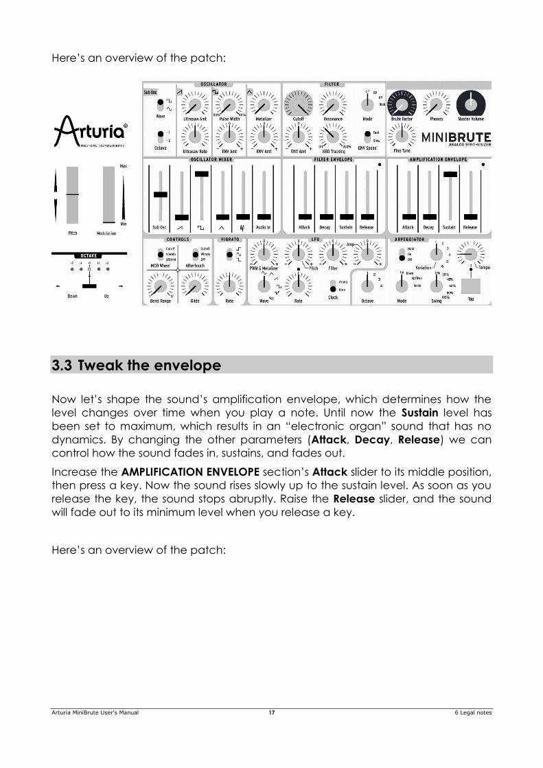
Here’s an overview of the patch:
3.3 Tweak the envelope
Now let’s shape the sound’s amplification envelope, which determines how the
level changes over time when you play a note. Until now the Sustain level has
been set to maximum, which results in an “electronic organ” sound that has no
dynamics. By changing the other parameters (Attack, Decay, Release) we can
control how the sound fades in, sustains, and fades out.
Increase the AMPLIFICATION ENVELOPE section’s Attack slider to its middle position,
then press a key. Now the sound rises slowly up to the sustain level. As soon as you
release the key, the sound stops abruptly. Raise the Release slider, and the sound
will fade out to its minimum level when you release a key.
Here’s an overview of the patch:
Arturia MiniBrute User's Manual 18 6 Legal notes
Now set these four envelope sliders all the way down, and raise the Decay slider to
maximum. Press and hold down a key: the sound appears as soon as you press the
key, and slowly fades out to the minimum level. While pressing a key repeatedly,
slowly turn down the Decay slider: the sound will fade out more rapidly. In the
lowest range of the slider, you’ll hear short, percussive sounds.
Now that we’ve covered amplification envelope basics, let’s check out something
even more fun.
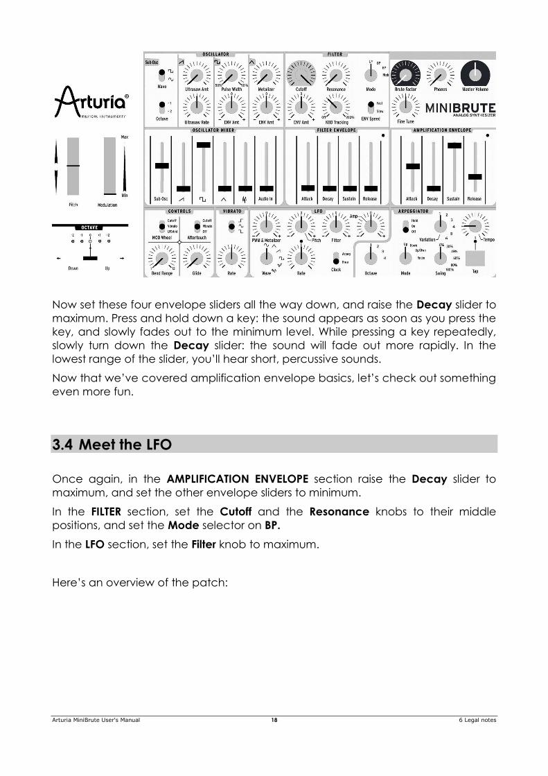
3.4 Meet the LFO
Once again, in the AMPLIFICATION ENVELOPE section raise the Decay slider to
maximum, and set the other envelope sliders to minimum.
In the FILTER section, set the Cutoff and the Resonance knobs to their middle
positions, and set the Mode selector on BP.
In the LFO section, set the Filter knob to maximum.
Here’s an overview of the patch:
Arturia MiniBrute User's Manual 19 6 Legal notes
Press and hold a key: you should hear timbre sweeps, a bit like a didgeridoo, at a
rhythm indicated by the red LED. Tweak the Rate knob to slow down or accelerate
this wah-wah effect, and play with the filter's Resonance to accentuate it.
Be cautious, you've just entered the Dubstep realm...
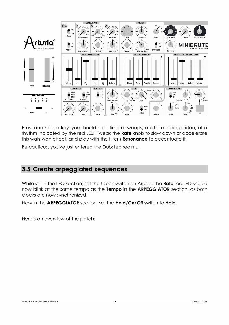
3.5 Create arpeggiated sequences
While still in the LFO section, set the Clock switch on Arpeg. The Rate red LED should
now blink at the same tempo as the Tempo in the ARPEGGIATOR section, as both
clocks are now synchronized.
Now in the ARPEGGIATOR section, set the Hold/On/Off switch to Hold.
Here’s an overview of the patch:
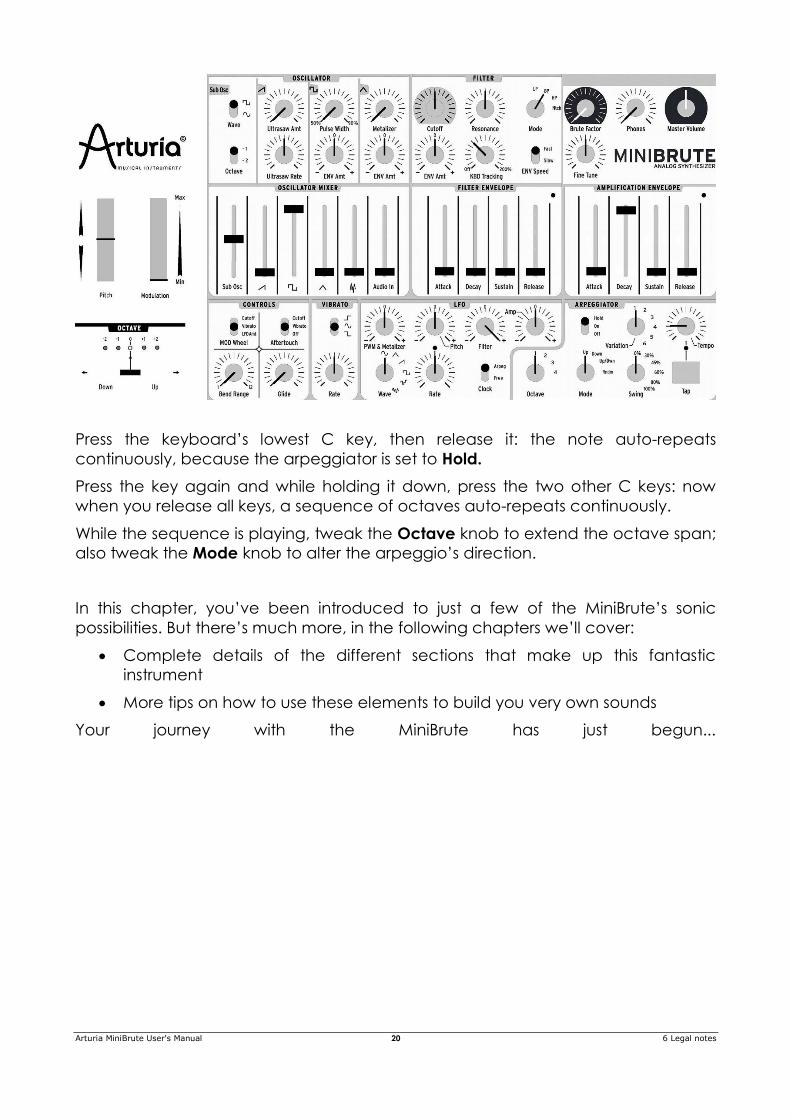
Arturia MiniBrute User's Manual 20 6 Legal notes
Press the keyboard’s lowest C key, then release it: the note auto-repeats
continuously, because the arpeggiator is set to Hold.
Press the key again and while holding it down, press the two other C keys: now
when you release all keys, a sequence of octaves auto-repeats continuously.
While the sequence is playing, tweak the Octave knob to extend the octave span;
also tweak the Mode knob to alter the arpeggio’s direction.
In this chapter, you’ve been introduced to just a few of the MiniBrute’s sonic
possibilities. But there’s much more, in the following chapters we’ll cover:
Complete details of the different sections that make up this fantastic
instrument
More tips on how to use these elements to build you very own sounds
Your journey with the MiniBrute has just begun...
Arturia MiniBrute User's Manual 21 6 Legal notes
4 GENERAL DESCRIPTION
Your MiniBrute is a true analog sound synthesizer, so all sounds are produced by
analog electronic circuits. No digital computer circuitry is involved in the
generation, filtering, or basic control of sound. This is one of the reasons why
MiniBrute creates rich, animated, and lively electronic sounds.
4.1 Analog synthesizer architecture
The analog sound production chain uses a classical approach called subtractive
synthesis. The basic sound generator is a waveform with a rich harmonic content;
filtering then “subtracts” harmonics to create new variations on the original timbre.
Subsequent circuits (an envelope generator in conjunction with a VCA, or voltage-
controller amplifier) alter the level in a precise way to create dynamics.
4.1.1 Signal generators
The signal generators are the circuits that produce the basic waveforms for sound
creation. There are two basic categories: pitched signal generators and the
unpitched signal generators.
4.1.1.1 Pitched signal generator (oscillators)
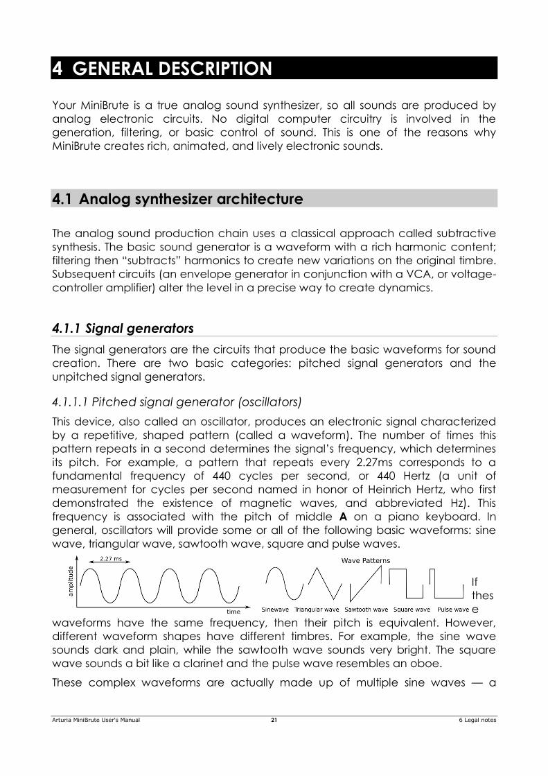
This device, also called an oscillator, produces an electronic signal characterized
by a repetitive, shaped pattern (called a waveform). The number of times this
pattern repeats in a second determines the signal’s frequency, which determines
its pitch. For example, a pattern that repeats every 2.27ms corresponds to a
fundamental frequency of 440 cycles per second, or 440 Hertz (a unit of
measurement for cycles per second named in honor of Heinrich Hertz, who first
demonstrated the existence of magnetic waves, and abbreviated Hz). This
frequency is associated with the pitch of middle A on a piano keyboard. In
general, oscillators will provide some or all of the following basic waveforms: sine
wave, triangular wave, sawtooth wave, square and pulse waves.
If
thes
e
waveforms have the same frequency, then their pitch is equivalent. However,
different waveform shapes have different timbres. For example, the sine wave
sounds dark and plain, while the sawtooth wave sounds very bright. The square
wave sounds a bit like a clarinet and the pulse wave resembles an oboe.
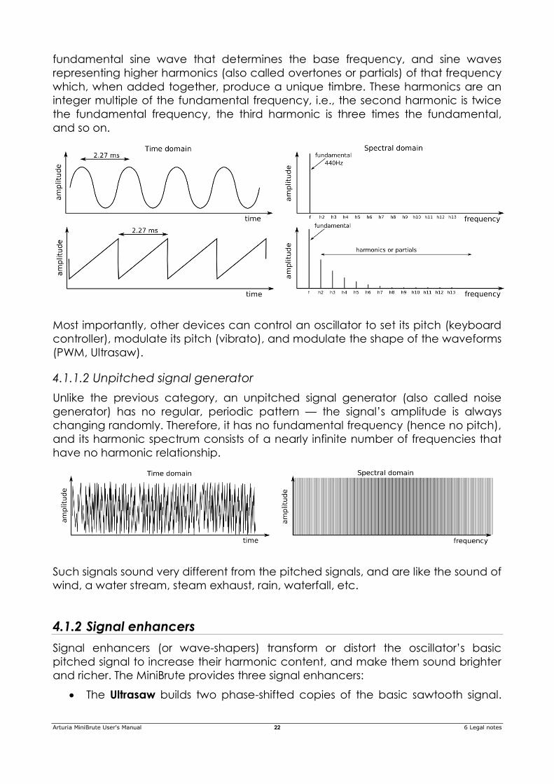
These complex waveforms are actually made up of multiple sine waves — a
Arturia MiniBrute User's Manual 22 6 Legal notes
fundamental sine wave that determines the base frequency, and sine waves
representing higher harmonics (also called overtones or partials) of that frequency
which, when added together, produce a unique timbre. These harmonics are an
integer multiple of the fundamental frequency, i.e., the second harmonic is twice
the fundamental frequency, the third harmonic is three times the fundamental,
and so on.
Most importantly, other devices can control an oscillator to set its pitch (keyboard
controller), modulate its pitch (vibrato), and modulate the shape of the waveforms
(PWM, Ultrasaw).
4.1.1.2 Unpitched signal generator
Unlike the previous category, an unpitched signal generator (also called noise
generator) has no regular, periodic pattern — the signal’s amplitude is always
changing randomly. Therefore, it has no fundamental frequency (hence no pitch),
and its harmonic spectrum consists of a nearly infinite number of frequencies that
have no harmonic relationship.
Such signals sound very different from the pitched signals, and are like the sound of
wind, a water stream, steam exhaust, rain, waterfall, etc.
4.1.2 Signal enhancers
Signal enhancers (or wave-shapers) transform or distort the oscillator’s basic
pitched signal to increase their harmonic content, and make them sound brighter
and richer. The MiniBrute provides three signal enhancers:
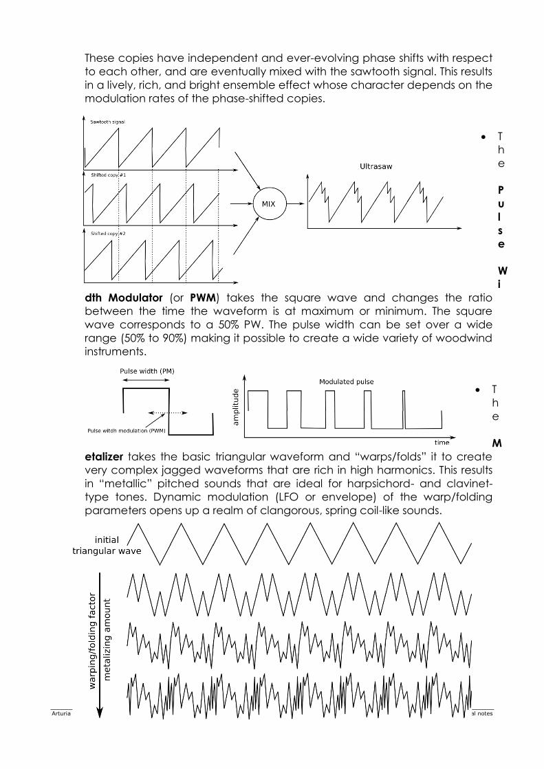
The Ultrasaw builds two phase-shifted copies of the basic sawtooth signal.
Arturia MiniBrute User's Manual 23 6 Legal notes
These copies have independent and ever-evolving phase shifts with respect
to each other, and are eventually mixed with the sawtooth signal. This results
in a lively, rich, and bright ensemble effect whose character depends on the
modulation rates of the phase-shifted copies.
T
h
e
P
u
l
s
e
W
i
dth Modulator (or PWM) takes the square wave and changes the ratio
between the time the waveform is at maximum or minimum. The square
wave corresponds to a 50% PW. The pulse width can be set over a wide
range (50% to 90%) making it possible to create a wide variety of woodwind
instruments.
T
h
e
M
etalizer takes the basic triangular waveform and “warps/folds” it to create
very complex jagged waveforms that are rich in high harmonics. This results
in “metallic” pitched sounds that are ideal for harpsichord- and clavinet-
type tones. Dynamic modulation (LFO or envelope) of the warp/folding
parameters opens up a realm of clangorous, spring coil-like sounds.
Arturia MiniBrute User's Manual 24 6 Legal notes
4.1.3 Filter
4.1.3.1 What is a filter?
In general, a filter follows the signal generator and signal enhancers, and modifies
the spectral content of the signal or signals. This can involve either attenuating
(filtering out) or emphasizing (resonating) particular overtones and partial, and
these changes can be either static or dynamic. Filters are very important circuits
whose design contributes greatly to the a synthesizer’s sound and character.
4.1.3.2 Filter types: Low-pass, Band-pass, High-pass and Notch
A filter can operate in various ways or modes. These modes are called transfer
functions or spectral responses. In the MiniBrute the filter can operate either as a
low-pass filter, a band-pass filter, a high-pass filter, or a notch filter.
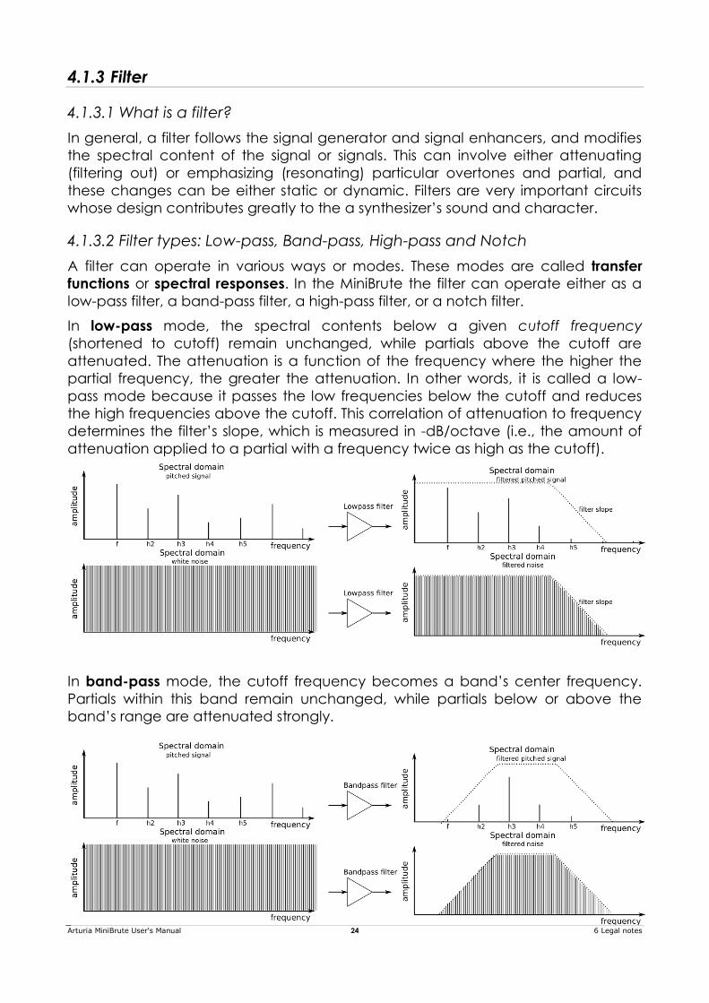
In low-pass mode, the spectral contents below a given cutoff frequency
(shortened to cutoff) remain unchanged, while partials above the cutoff are
attenuated. The attenuation is a function of the frequency where the higher the
partial frequency, the greater the attenuation. In other words, it is called a low-
pass mode because it passes the low frequencies below the cutoff and reduces
the high frequencies above the cutoff. This correlation of attenuation to frequency
determines the filter’s slope, which is measured in -dB/octave (i.e., the amount of
attenuation applied to a partial with a frequency twice as high as the cutoff).
In band-pass mode, the cutoff frequency becomes a band’s center frequency.
Partials within this band remain unchanged, while partials below or above the
band’s range are attenuated strongly.
Arturia MiniBrute User's Manual 25 6 Legal notes
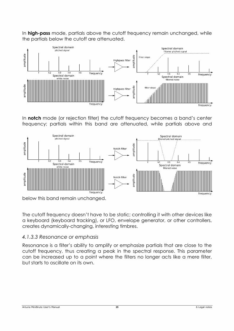
In high-pass mode, partials above the cutoff frequency remain unchanged, while
the partials below the cutoff are attenuated.
In notch mode (or rejection filter) the cutoff frequency becomes a band’s center
frequency; partials within this band are attenuated, while partials above and
below this band remain unchanged.
The cutoff frequency doesn’t have to be static; controlling it with other devices like
a keyboard (keyboard tracking), or LFO, envelope generator, or other controllers,
creates dynamically-changing, interesting timbres.
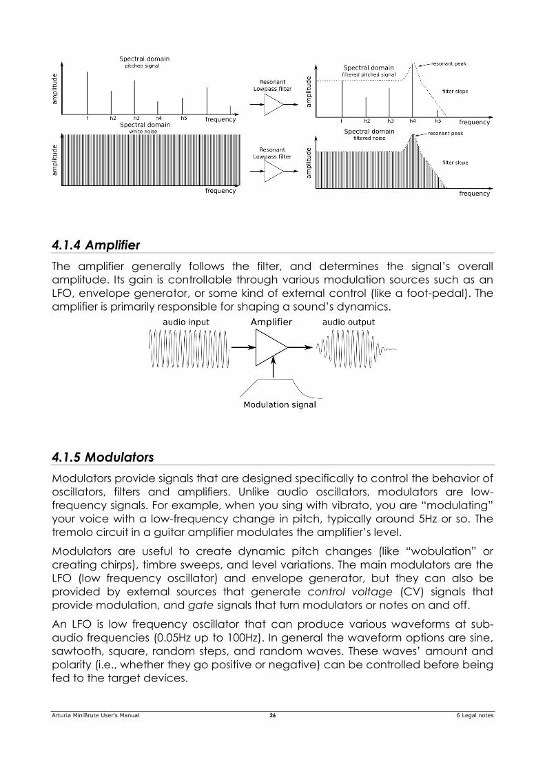
4.1.3.3 Resonance or emphasis
Resonance is a filter’s ability to amplify or emphasize partials that are close to the
cutoff frequency, thus creating a peak in the spectral response. This parameter
can be increased up to a point where the filters no longer acts like a mere filter,
but starts to oscillate on its own.
Arturia MiniBrute User's Manual 26 6 Legal notes
4.1.4 Amplifier
The amplifier generally follows the filter, and determines the signal’s overall
amplitude. Its gain is controllable through various modulation sources such as an
LFO, envelope generator, or some kind of external control (like a foot-pedal). The
amplifier is primarily responsible for shaping a sound’s dynamics.
4.1.5 Modulators
Modulators provide signals that are designed specifically to control the behavior of
oscillators, filters and amplifiers. Unlike audio oscillators, modulators are low-
frequency signals. For example, when you sing with vibrato, you are “modulating”
your voice with a low-frequency change in pitch, typically around 5Hz or so. The
tremolo circuit in a guitar amplifier modulates the amplifier’s level.
Modulators are useful to create dynamic pitch changes (like “wobulation” or
creating chirps), timbre sweeps, and level variations. The main modulators are the
LFO (low frequency oscillator) and envelope generator, but they can also be
provided by external sources that generate control voltage (CV) signals that
provide modulation, and gate signals that turn modulators or notes on and off.
An LFO is low frequency oscillator that can produce various waveforms at sub-
audio frequencies (0.05Hz up to 100Hz). In general the waveform options are sine,
sawtooth, square, random steps, and random waves. These waves’ amount and
polarity (i.e., whether they go positive or negative) can be controlled before being
fed to the target devices.
Arturia MiniBrute User's Manual 27 6 Legal notes
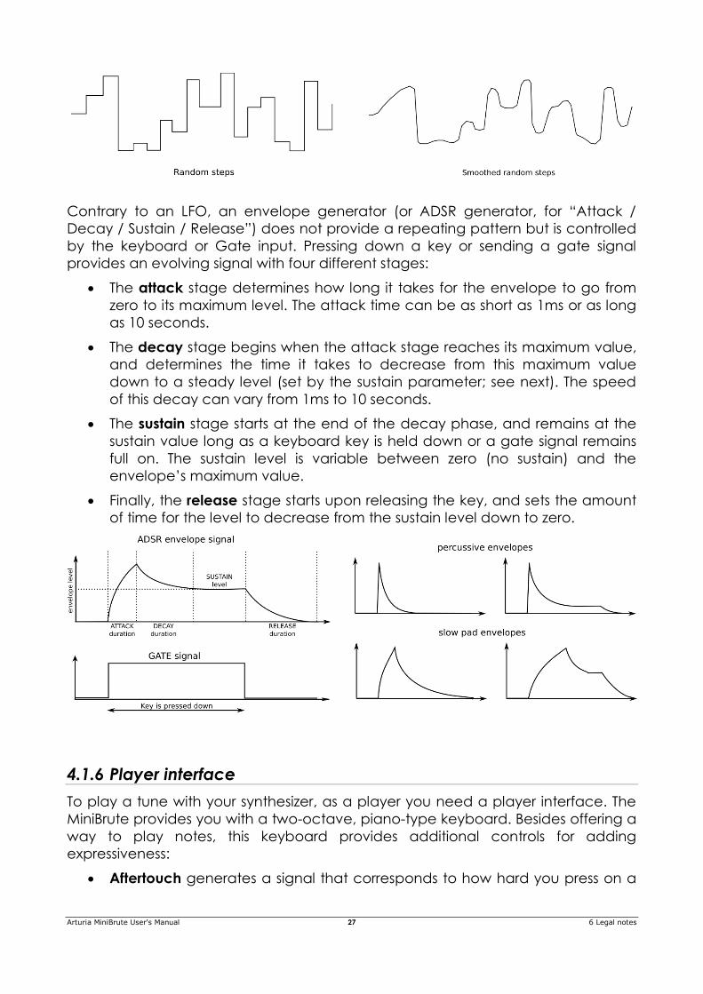
Contrary to an LFO, an envelope generator (or ADSR generator, for “Attack /
Decay / Sustain / Release”) does not provide a repeating pattern but is controlled
by the keyboard or Gate input. Pressing down a key or sending a gate signal
provides an evolving signal with four different stages:
The attack stage determines how long it takes for the envelope to go from
zero to its maximum level. The attack time can be as short as 1ms or as long
as 10 seconds.
The decay stage begins when the attack stage reaches its maximum value,
and determines the time it takes to decrease from this maximum value
down to a steady level (set by the sustain parameter; see next). The speed
of this decay can vary from 1ms to 10 seconds.
The sustain stage starts at the end of the decay phase, and remains at the
sustain value long as a keyboard key is held down or a gate signal remains
full on. The sustain level is variable between zero (no sustain) and the
envelope’s maximum value.
Finally, the release stage starts upon releasing the key, and sets the amount
of time for the level to decrease from the sustain level down to zero.
4.1.6 Player interface
To play a tune with your synthesizer, as a player you need a player interface. The
MiniBrute provides you with a two-octave, piano-type keyboard. Besides offering a
way to play notes, this keyboard provides additional controls for adding
expressiveness:
Aftertouch generates a signal that corresponds to how hard you press on a
Arturia MiniBrute User's Manual 28 6 Legal notes
key after it’s down. You can use this signal to modulate vibrato, filter cutoff,
and other parameters.
Velocity corresponds to the dynamics of your playing, and similarly to
aftertouch, can modulate multiple parameters.
Transposition allows shifting the keyboard’s note range over six octaves.
The pitch bend wheel allows adding real-time pitch changes, like bending
strings on a guitar.
The modulation wheel allows applying real-time modulation changes to
various parameters. For example, it could add vibrato, or change the filter
cutoff as you move it.
An arpeggiator automates the creation of repeating sequences of notes.
Alternative ways of playing the synthesizer are available through MIDI control and
external CV/GATE signals.
4.1.7 Inputs and outputs
In order to hear the MiniBrute, its audio output needs to connect to an audio
amplifier either directly or through a mixer console (or use the Headphones
output).
As to control, the MiniBrute can accept control voltage signals from devices like an
analog step sequencer or MIDI controller (e.g., a MIDI drum pad or wind
controller), or even audio signals from an external sound source such as a
microphone or electric guitar.
The means to control other instruments, or be controlled by other instruments, is
provided by the collection of inputs and outputs such as MIDI in and out, an
external audio input, and CV and GATE inputs and outputs.
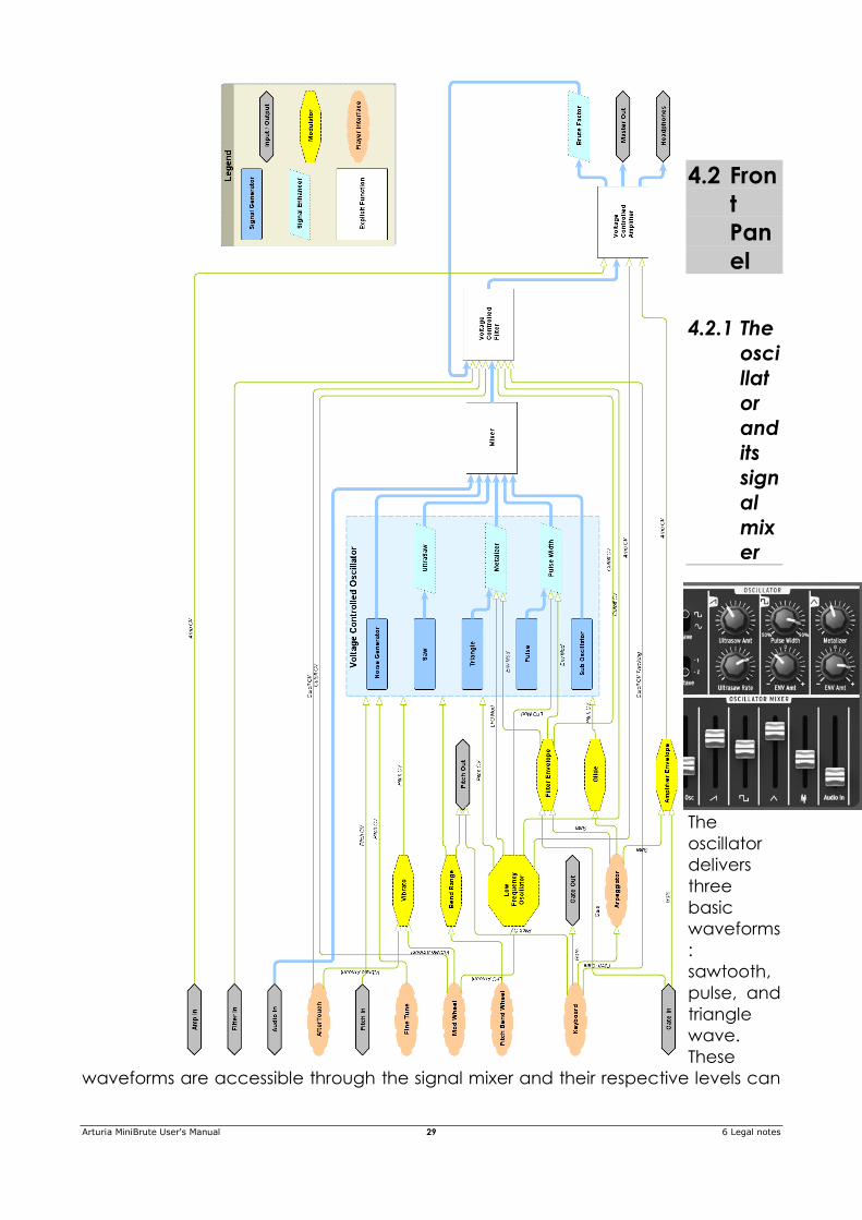
4.1.8 MiniBrute diagram
Arturia MiniBrute User's Manual 29 6 Legal notes
4.2 Fron
t
Pan
el
4.2.1 The
osci
llat
or
and
its
sign
al
mix
er
The
oscillator
delivers
three
basic
waveforms
:
sawtooth,
pulse, and
triangle
wave.
These
waveforms are accessible through the signal mixer and their respective levels can
Arturia MiniBrute User's Manual 30 6 Legal notes
be adjusted with the slider potentiometers. A sub-oscillator is available to create
sub-bass sounds. The mixer also controls the level of noise and of external audio (if
an external source is plugged in the rear panel’s audio in jack). The mixed signals
then feed the filter. The waveforms can also be modified using signal enhancers
(Ultrasaw, Pulse Width Modulation and Metalizer).
4.2.1.1 The waveforms
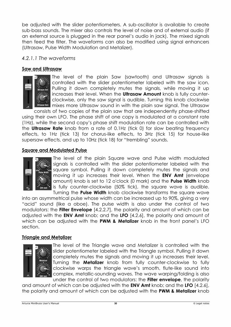
Saw and Ultrasaw
The level of the plain Saw (sawtooth) and Ultrasaw signals is
controlled with the slider potentiometer labeled with the saw icon.
Pulling it down completely mutes the signals, while moving it up
increases their level. When the Ultrasaw Amount knob is fully counter-
clockwise, only the saw signal is audible. Turning this knob clockwise
mixes more Ultrasaw sound in with the plain saw signal. The Ultrasaw
consists of two copies of the plain saw that are independently phase-shifted
using their own LFO. The phase shift of one copy is modulated at a constant rate
(1Hz), while the second copy’s phase shift modulation rate can be controlled with
the Ultrasaw Rate knob from a rate of 0.1Hz (tick 0) for slow beating frequency
effects, to 1Hz (tick 13) for chorus-like effects, to 3Hz (tick 15) for house-like
supersaw effects, and up to 10Hz (tick 18) for “trembling” sounds.
Square and Modulated Pulse
The level of the plain Square wave and Pulse width modulated
signals is controlled with the slider potentiometer labeled with the
square symbol. Pulling it down completely mutes the signals and
moving it up increases their level. When the ENV Amt (envelope
amount) knob is set to 12 o'clock (0 mark) and the Pulse Width knob
is fully counter-clockwise (50% tick), the square wave is audible.
Turning the Pulse Width knob clockwise transforms the square wave
into an asymmetrical pulse whose width can be increased up to 90%, giving a very
“acid” sound (like a oboe). The pulse width is also under the control of two
modulators: the Filter Envelope [4.2.2.7], the polarity and amount of which can be
adjusted with the ENV Amt knob; and the LFO [4.2.6], the polarity and amount of
which can be adjusted with the PWM & Metalizer knob in the front panel’s LFO
section.
Triangle and Metalizer
The level of the Triangle wave and Metalizer is controlled with the
slider potentiometer labeled with the Triangle symbol. Pulling it down
completely mutes the signals and moving it up increases their level.
Turning the Metalizer knob from fully counter-clockwise to fully
clockwise warps the triangle wave’s smooth, flute-like sound into
complex, metallic-sounding waves. The wave warping/folding is also
under the control of two modulators: the Filter envelope, the polarity
and amount of which can be adjusted with the ENV Amt knob; and the LFO [4.2.6],
the polarity and amount of which can be adjusted with the PWM & Metalizer knob
Arturia MiniBrute User's Manual 31 6 Legal notes
[4.2.6.4] in the front panel’s LFO section.
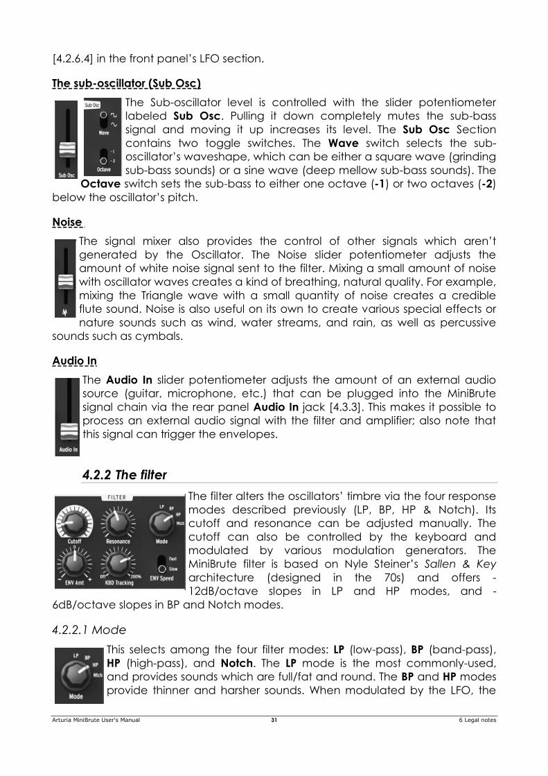
The sub-oscillator (Sub Osc)
The Sub-oscillator level is controlled with the slider potentiometer
labeled Sub Osc. Pulling it down completely mutes the sub-bass
signal and moving it up increases its level. The Sub Osc Section
contains two toggle switches. The Wave switch selects the sub-
oscillator’s waveshape, which can be either a square wave (grinding
sub-bass sounds) or a sine wave (deep mellow sub-bass sounds). The
Octave switch sets the sub-bass to either one octave (-1) or two octaves (-2)
below the oscillator’s pitch.
Noise
The signal mixer also provides the control of other signals which aren’t
generated by the Oscillator. The Noise slider potentiometer adjusts the
amount of white noise signal sent to the filter. Mixing a small amount of noise
with oscillator waves creates a kind of breathing, natural quality. For example,
mixing the Triangle wave with a small quantity of noise creates a credible
flute sound. Noise is also useful on its own to create various special effects or
nature sounds such as wind, water streams, and rain, as well as percussive
sounds such as cymbals.
Audio In
The Audio In slider potentiometer adjusts the amount of an external audio
source (guitar, microphone, etc.) that can be plugged into the MiniBrute
signal chain via the rear panel Audio In jack [4.3.3]. This makes it possible to
process an external audio signal with the filter and amplifier; also note that
this signal can trigger the envelopes.
4.2.2 The filter
The filter alters the oscillators’ timbre via the four response
modes described previously (LP, BP, HP & Notch). Its
cutoff and resonance can be adjusted manually. The
cutoff can also be controlled by the keyboard and
modulated by various modulation generators. The
MiniBrute filter is based on Nyle Steiner’s Sallen & Key
architecture (designed in the 70s) and offers -
12dB/octave slopes in LP and HP modes, and -
6dB/octave slopes in BP and Notch modes.
4.2.2.1 Mode
This selects among the four filter modes: LP (low-pass), BP (band-pass),
HP (high-pass), and Notch. The LP mode is the most commonly-used,
and provides sounds which are full/fat and round. The BP and HP modes
provide thinner and harsher sounds. When modulated by the LFO, the
Arturia MiniBrute User's Manual 32 6 Legal notes
Notch filter mode sounds similar to a phaser effect pedal.
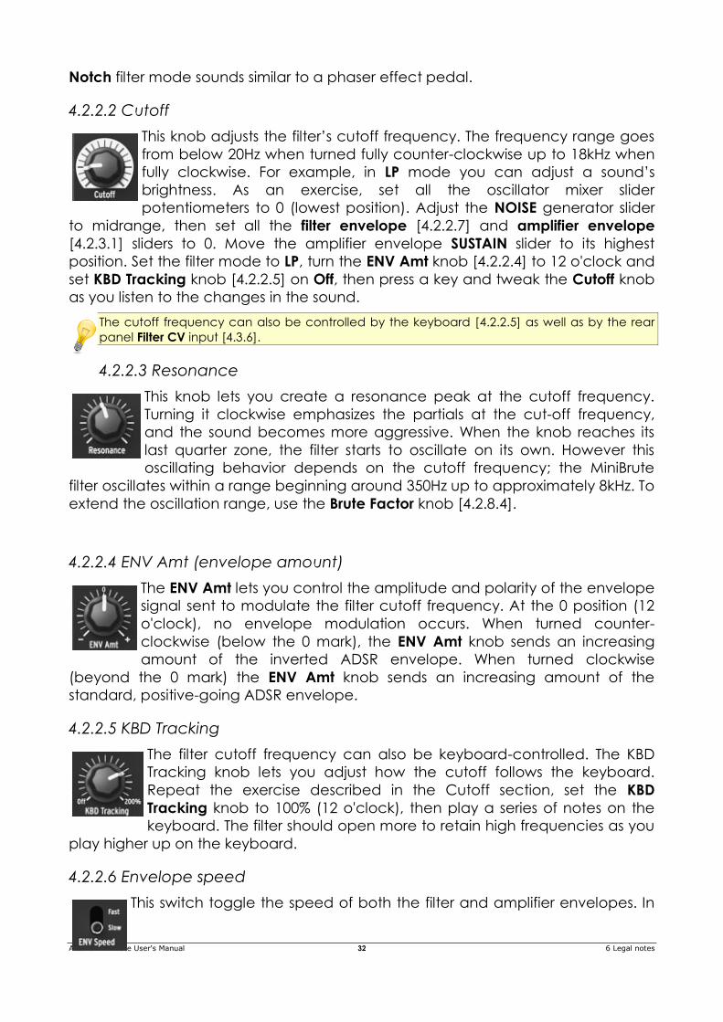
4.2.2.2 Cutoff
This knob adjusts the filter’s cutoff frequency. The frequency range goes
from below 20Hz when turned fully counter-clockwise up to 18kHz when
fully clockwise. For example, in LP mode you can adjust a sound’s
brightness. As an exercise, set all the oscillator mixer slider
potentiometers to 0 (lowest position). Adjust the NOISE generator slider
to midrange, then set all the filter envelope [4.2.2.7] and amplifier envelope
[4.2.3.1] sliders to 0. Move the amplifier envelope SUSTAIN slider to its highest
position. Set the filter mode to LP, turn the ENV Amt knob [4.2.2.4] to 12 o'clock and
set KBD Tracking knob [4.2.2.5] on Off, then press a key and tweak the Cutoff knob
as you listen to the changes in the sound.
The cutoff frequency can also be controlled by the keyboard [4.2.2.5] as well as by the rear
panel Filter CV input [4.3.6].
4.2.2.3 Resonance
This knob lets you create a resonance peak at the cutoff frequency.
Turning it clockwise emphasizes the partials at the cut-off frequency,
and the sound becomes more aggressive. When the knob reaches its
last quarter zone, the filter starts to oscillate on its own. However this
oscillating behavior depends on the cutoff frequency; the MiniBrute
filter oscillates within a range beginning around 350Hz up to approximately 8kHz. To
extend the oscillation range, use the Brute Factor knob [4.2.8.4].
4.2.2.4 ENV Amt (envelope amount)
The ENV Amt lets you control the amplitude and polarity of the envelope
signal sent to modulate the filter cutoff frequency. At the 0 position (12
o'clock), no envelope modulation occurs. When turned counter-
clockwise (below the 0 mark), the ENV Amt knob sends an increasing
amount of the inverted ADSR envelope. When turned clockwise
(beyond the 0 mark) the ENV Amt knob sends an increasing amount of the
standard, positive-going ADSR envelope.
4.2.2.5 KBD Tracking
The filter cutoff frequency can also be keyboard-controlled. The KBD
Tracking knob lets you adjust how the cutoff follows the keyboard.
Repeat the exercise described in the Cutoff section, set the KBD
Tracking knob to 100% (12 o'clock), then play a series of notes on the
keyboard. The filter should open more to retain high frequencies as you
play higher up on the keyboard.
4.2.2.6 Envelope speed
This switch toggle the speed of both the filter and amplifier envelopes. In
Arturia MiniBrute User's Manual 33 6 Legal notes
fast mode, the ADSR curves can be very rapid, which is useful when creating
“snappy” and percussive sounds. In the slow mode, the ADSR curves can be very
slow, making them suitable for slow, evolving sounds like pads.
4.2.2.7 Filter Envelope
In normal mode, the Filter envelope is triggered by the
keyboard GATE signal. It can also be triggered by other
GATE sources such as the Arpeggiator clock [] or the rear
panel’s external GATE IN jack [4.3.6]. Note that depending
on the position of the GATE Source switch located on the
rear panel [], the filter envelope is under the control of
either the keyboard GATE signal, the automatic GATE from
the external Audio input [4.3.3], or the hold position of the
GATE switch.
The Attack slider sets the duration of the envelope’s first stage. Depending on the
filter section’s ENV Speed switch [4.2.2.6] the Attack time ranges from 1ms to 1s or
from 10ms to 10s.
The Decay slider sets the duration of the envelope’s second stage. Depending on
the filter section’s ENV Speed switch [4.2.2.6] the Decay time ranges from 1ms to 1s
or from 10ms to 10s.
The Sustain slider sets the level of the envelope’s sustain stage.
The Release slider sets the duration of the envelope’s final stage. Depending on
the filter section’s ENV Speed switch [4.2.2.6] the Release time ranges from 1ms to
1s or from 10ms to 10s.
A LED indicator shows the amount of filter envelope sent to filter. The LED’s
brightness depends both on the envelope signal amplitude and on the Velocity
signal sent by the keyboard (when the Velocity function has been enabled over
USB by the MiniBrute Connection software; see the Software section of this
manual).
4.2.3 The amplifier
The amplifier controls the sound’s amplitude dynamics, as determined by the
Amplifier Envelope and LFO parameters.
4.2.3.1 Amplifier Envelope
In normal mode, the Amplifier envelope is triggered by the
keyboard GATE signal. It can also be triggered by other
GATE sources such as the Arpeggiator clock [] or the rear
panel’s external GATE IN jack [4.3.6]. Note that depending
on the position of the GATE switch located on the rear panel
[] the amplifier envelope is under the control of either the
keyboard GATE signal, the automatic GATE from the
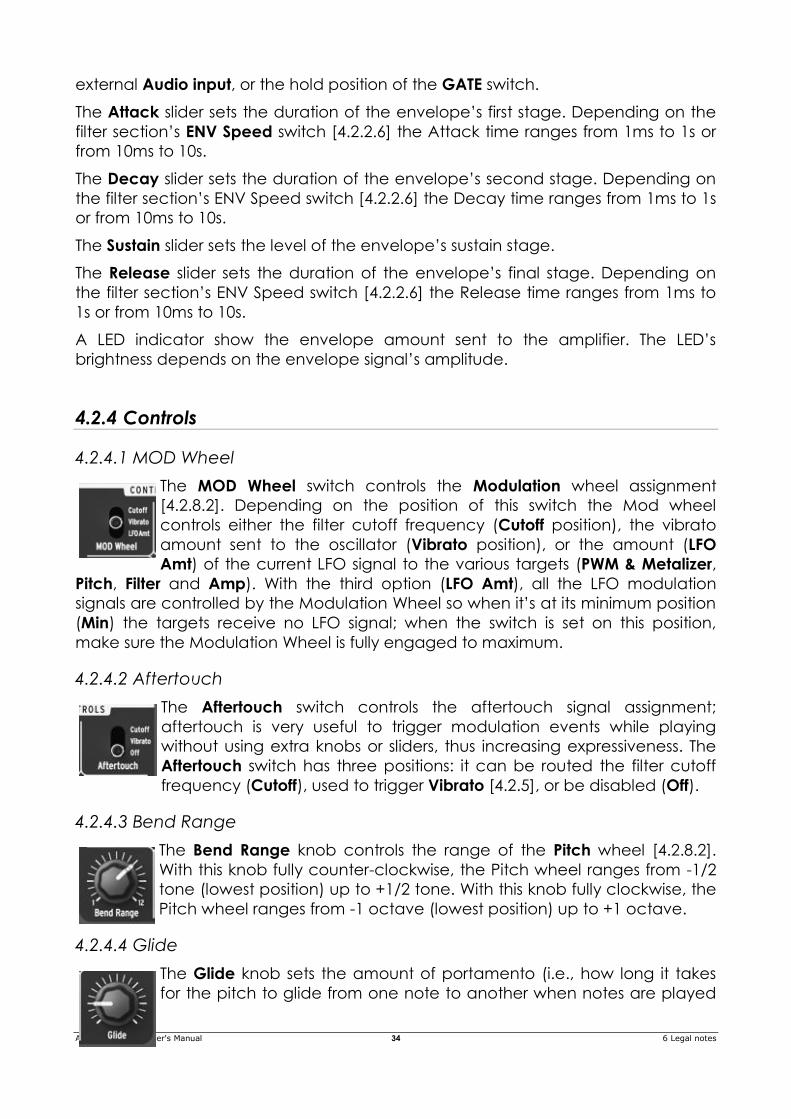
Arturia MiniBrute User's Manual 34 6 Legal notes
external Audio input, or the hold position of the GATE switch.
The Attack slider sets the duration of the envelope’s first stage. Depending on the
filter section’s ENV Speed switch [4.2.2.6] the Attack time ranges from 1ms to 1s or
from 10ms to 10s.
The Decay slider sets the duration of the envelope’s second stage. Depending on
the filter section’s ENV Speed switch [4.2.2.6] the Decay time ranges from 1ms to 1s
or from 10ms to 10s.
The Sustain slider sets the level of the envelope’s sustain stage.
The Release slider sets the duration of the envelope’s final stage. Depending on
the filter section’s ENV Speed switch [4.2.2.6] the Release time ranges from 1ms to
1s or from 10ms to 10s.
A LED indicator show the envelope amount sent to the amplifier. The LED’s
brightness depends on the envelope signal’s amplitude.
4.2.4 Controls
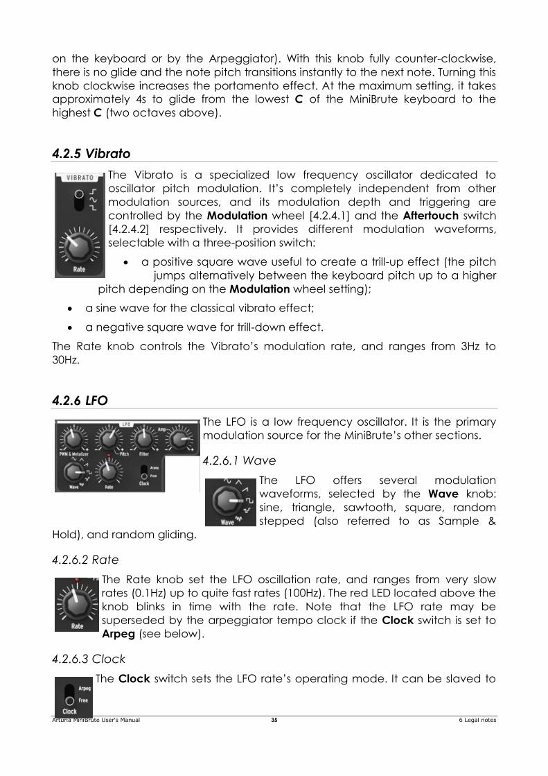
4.2.4.1 MOD Wheel
The MOD Wheel switch controls the Modulation wheel assignment
[4.2.8.2]. Depending on the position of this switch the Mod wheel
controls either the filter cutoff frequency (Cutoff position), the vibrato
amount sent to the oscillator (Vibrato position), or the amount (LFO
Amt) of the current LFO signal to the various targets (PWM & Metalizer,
Pitch, Filter and Amp). With the third option (LFO Amt), all the LFO modulation
signals are controlled by the Modulation Wheel so when it’s at its minimum position
(Min) the targets receive no LFO signal; when the switch is set on this position,
make sure the Modulation Wheel is fully engaged to maximum.
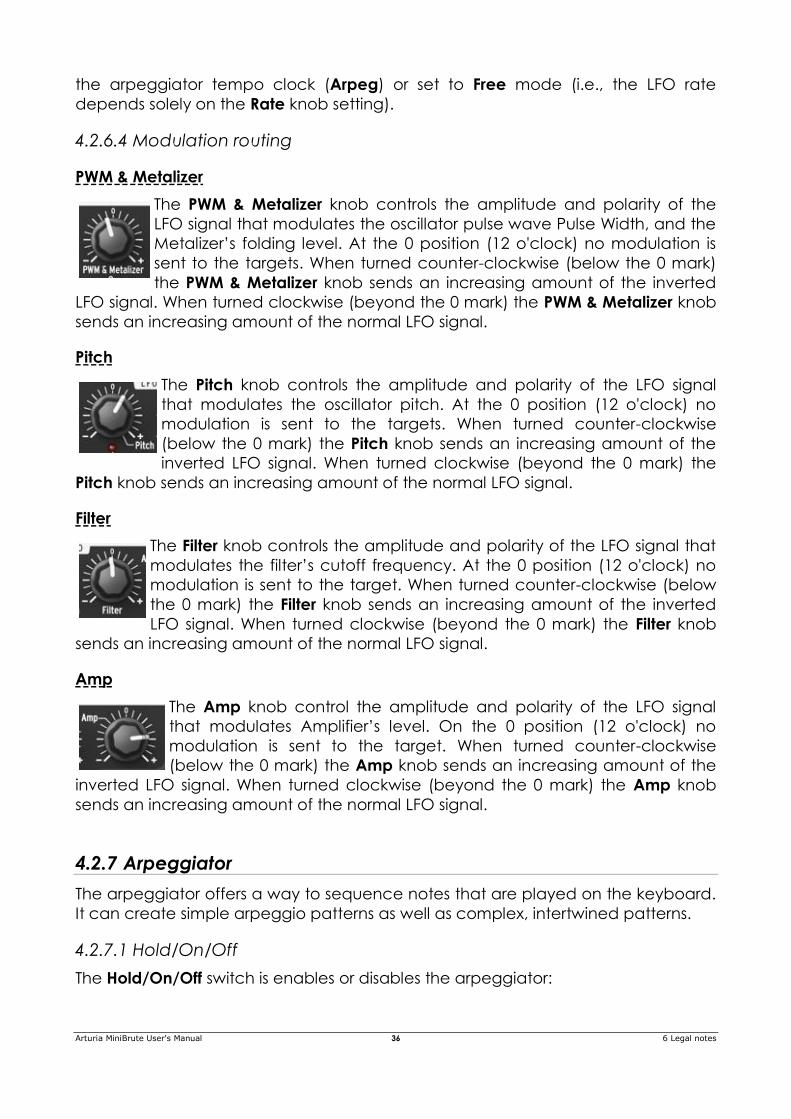
4.2.4.2 Aftertouch
The Aftertouch switch controls the aftertouch signal assignment;
aftertouch is very useful to trigger modulation events while playing
without using extra knobs or sliders, thus increasing expressiveness. The
Aftertouch switch has three positions: it can be routed the filter cutoff
frequency (Cutoff), used to trigger Vibrato [4.2.5], or be disabled (Off).
4.2.4.3 Bend Range
The Bend Range knob controls the range of the Pitch wheel [4.2.8.2].
With this knob fully counter-clockwise, the Pitch wheel ranges from -1/2
tone (lowest position) up to +1/2 tone. With this knob fully clockwise, the
Pitch wheel ranges from -1 octave (lowest position) up to +1 octave.
4.2.4.4 Glide
The Glide knob sets the amount of portamento (i.e., how long it takes
for the pitch to glide from one note to another when notes are played
Arturia MiniBrute User's Manual 35 6 Legal notes
on the keyboard or by the Arpeggiator). With this knob fully counter-clockwise,
there is no glide and the note pitch transitions instantly to the next note. Turning this
knob clockwise increases the portamento effect. At the maximum setting, it takes
approximately 4s to glide from the lowest C of the MiniBrute keyboard to the
highest C (two octaves above).
4.2.5 Vibrato
The Vibrato is a specialized low frequency oscillator dedicated to
oscillator pitch modulation. It’s completely independent from other
modulation sources, and its modulation depth and triggering are
controlled by the Modulation wheel [4.2.4.1] and the Aftertouch switch
[4.2.4.2] respectively. It provides different modulation waveforms,
selectable with a three-position switch:
a positive square wave useful to create a trill-up effect (the pitch
jumps alternatively between the keyboard pitch up to a higher
pitch depending on the Modulation wheel setting);
a sine wave for the classical vibrato effect;
a negative square wave for trill-down effect.
The Rate knob controls the Vibrato’s modulation rate, and ranges from 3Hz to
30Hz.
4.2.6 LFO
The LFO is a low frequency oscillator. It is the primary
modulation source for the MiniBrute’s other sections.
4.2.6.1 Wave
The LFO offers several modulation
waveforms, selected by the Wave knob:
sine, triangle, sawtooth, square, random
stepped (also referred to as Sample &
Hold), and random gliding.
4.2.6.2 Rate
The Rate knob set the LFO oscillation rate, and ranges from very slow
rates (0.1Hz) up to quite fast rates (100Hz). The red LED located above the
knob blinks in time with the rate. Note that the LFO rate may be
superseded by the arpeggiator tempo clock if the Clock switch is set to
Arpeg (see below).
4.2.6.3 Clock
The Clock switch sets the LFO rate’s operating mode. It can be slaved to
Arturia MiniBrute User's Manual 36 6 Legal notes
the arpeggiator tempo clock (Arpeg) or set to Free mode (i.e., the LFO rate
depends solely on the Rate knob setting).
4.2.6.4 Modulation routing
PWM & Metalizer
The PWM & Metalizer knob controls the amplitude and polarity of the
LFO signal that modulates the oscillator pulse wave Pulse Width, and the
Metalizer’s folding level. At the 0 position (12 o'clock) no modulation is
sent to the targets. When turned counter-clockwise (below the 0 mark)
the PWM & Metalizer knob sends an increasing amount of the inverted
LFO signal. When turned clockwise (beyond the 0 mark) the PWM & Metalizer knob
sends an increasing amount of the normal LFO signal.
Pitch
The Pitch knob controls the amplitude and polarity of the LFO signal
that modulates the oscillator pitch. At the 0 position (12 o'clock) no
modulation is sent to the targets. When turned counter-clockwise
(below the 0 mark) the Pitch knob sends an increasing amount of the
inverted LFO signal. When turned clockwise (beyond the 0 mark) the
Pitch knob sends an increasing amount of the normal LFO signal.
Filter
The Filter knob controls the amplitude and polarity of the LFO signal that
modulates the filter’s cutoff frequency. At the 0 position (12 o'clock) no
modulation is sent to the target. When turned counter-clockwise (below
the 0 mark) the Filter knob sends an increasing amount of the inverted
LFO signal. When turned clockwise (beyond the 0 mark) the Filter knob
sends an increasing amount of the normal LFO signal.
Amp
The Amp knob control the amplitude and polarity of the LFO signal
that modulates Amplifier’s level. On the 0 position (12 o'clock) no
modulation is sent to the target. When turned counter-clockwise
(below the 0 mark) the Amp knob sends an increasing amount of the
inverted LFO signal. When turned clockwise (beyond the 0 mark) the Amp knob
sends an increasing amount of the normal LFO signal.
4.2.7 Arpeggiator
The arpeggiator offers a way to sequence notes that are played on the keyboard.
It can create simple arpeggio patterns as well as complex, intertwined patterns.
4.2.7.1 Hold/On/Off
The Hold/On/Off switch is enables or disables the arpeggiator:
Arturia MiniBrute User's Manual 37 6 Legal notes
Off disables the arpeggiator, and the MiniBrute synthesizer is in “normal”
operation mode.
On activates the arpeggiator as long as keys are pressed down. In this case,
the arpeggiator repeatedly plays the notes in a sequence that corresponds
to the pitch order in which the keys were pressed. The played pattern can
also be modified by the other arpeggiator controls (Octave, Mode, Swing
and Variation knobs).
The Hold mode allows recording/playing back a sequence of notes without
needing to keep the key held down. The arpeggiator plays the pattern
repeatedly until you either press a new key or return the switch to the On or
Off positions. By default, all notes are pitch-sorted; however the Hold mode
can be toggled in a time-sorted notes mode through the MiniBrute
Connection software (see chapter for further details). In this mode, by
holding down the first note pressed and then adding other notes (or even
the same ones several times), you can build looped melodic sequences (up
to 16 notes).
4.2.7.2 Octave
The Octave knob determines the arpeggiator’s transposition range, from one to
four octaves.
4.2.7.3 Mode
The Mode switch chooses how the pool of arpeggiated notes will be sorted with
respect to playing order:
Up ...... sorts the pool by ascending pitch.
Down .. sorts the pool by descending pitch.
Up/Dwn first plays the pool in Up mode, then Down mode. The first and
last notes repeat.
Rndm .. picks notes randomly from the pool.
4.2.7.4 Swing
The Swing switch sets the swing amount applied to every even note in the
arpeggio, from a strictly “mechanical” groove to one that’s totally “off-the-
tempo.” 6 positions are selectable, with swing values varying from 50% (position 1)
to 75% (position 6).
4.2.7.5 Step
The step selector defines the tempo subdivisions to be used:
1/4 ...... quarter note, or one note on each step
1/8 ...... eighth note, or 2 notes per step
1/16 .... sixteenth note, or 4 notes per steps
1/4T..... quarter note (triplet), or 3 notes per 2 steps
Arturia MiniBrute User's Manual 38 6 Legal notes
1/8T..... eighth note (triplet), or 6 notes per 2 steps
1/16T .. sixteenth note (triplet), or 12 notes per 2 steps
4.2.7.6 Tempo & Tap
The Tempo knob sets the arpeggiator’s clock rate from 30 bpm to 260 bpm. The
red LED under the knob blinks in sync with the tempo beat.
The Tempo knob acts differently if MiniBrute detects an external MIDI clock on the
MIDI Input or USB connector:
With no external MIDI clock, the Tempo knob acts as expected — its position
sets the general BPM value.
An external MIDI clock deactivates the Tempo knob except at its extremes,
where it acts as a performance-oriented divider/multiplier. Fully counter-
clockwise halves the tempo, while fully clockwise doubles the tempo.
You can also define the tempo empirically with the Tap button, which provides a
“tap tempo” function. It too acts differently if MiniBrute detects an external MIDI
clock on the MIDI Input or USB connector, and works interactively with the Tempo
knob:
With no external MIDI clock, you can set the tempo with a “human touch”
by tapping on the pad at the desired beat. However when playing “live”
with human musicians, you may want to synchronize the synthesizer tempo
accurately with the other players; to do this, hold down the Tap pad. The
Tempo knob switches from absolute to relative mode, so so you can use it to
fine-tune the groove.
With an external MIDI clock, holding down the Tap pad transforms the
Tempo knob into a performance-oriented tempo modifier that ranges from -
100% (divide by 2) to +100% (multiply by 2). The current Tempo knob position
represents the MIDI-defined general tempo; moving the knob increases or
decreases tempo. MIDI clock control resumes if you release the Tap pad, so
the MiniBrute immediately gets back in sync with the general groove.
4.2.8 General controls
4.2.8.1 Keyboard
The MiniBrute keyboard covers a two-octave range, which can be extended using
the Octave Down/Up buttons [4.2.8.3]. The keyboard also provides aftertouch and
velocity control, and can also be used as fully polyphonic MIDI controller for other
devices via the rear panel MIDI out jack [4.3.5].
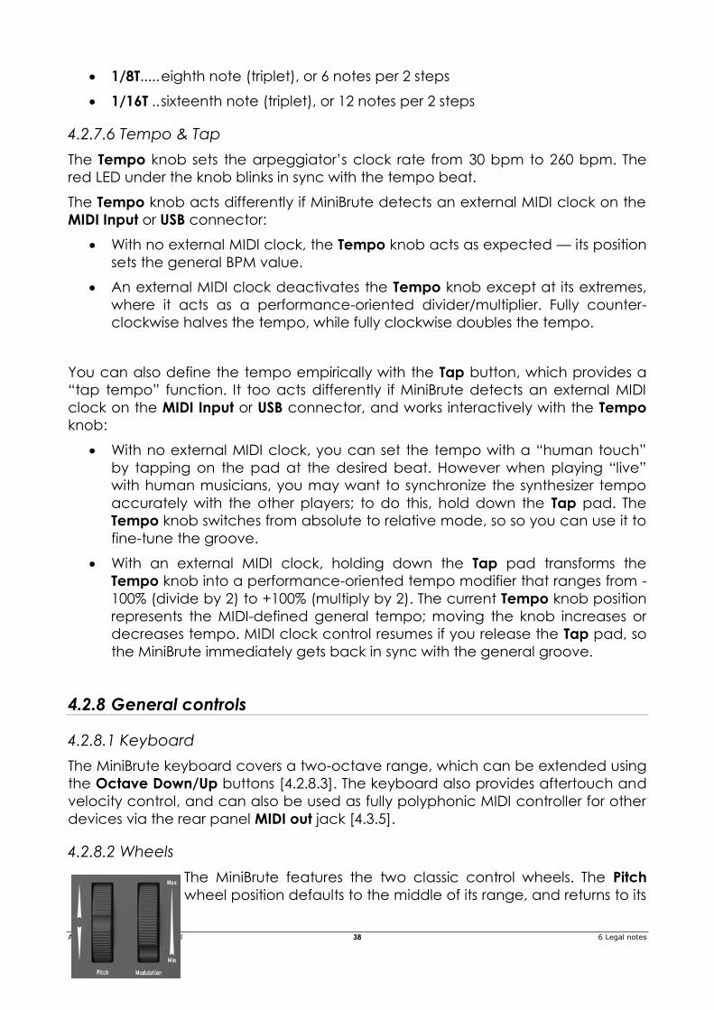
4.2.8.2 Wheels
The MiniBrute features the two classic control wheels. The Pitch
wheel position defaults to the middle of its range, and returns to its
Arturia MiniBrute User's Manual 39 6 Legal notes
default position when released. This wheel creates a pitch bend effect, where the
player can shift pitch smoothly up or down while playing a note. The amount of
shift is proportional to the rotation of the wheel, with its full range adjustable
between +/- one semitone to +/- one octave by the Bend Range knob [4.2.4.3].
The second wheel is the Modulation wheel. It sets the overall amount of
modulation signal sent to targets selected by the MOD Wheel switch [4.2.4.1].
Depending on the switch setting, it controls the Cutoff, the Vibrato or the LFO
amounts.
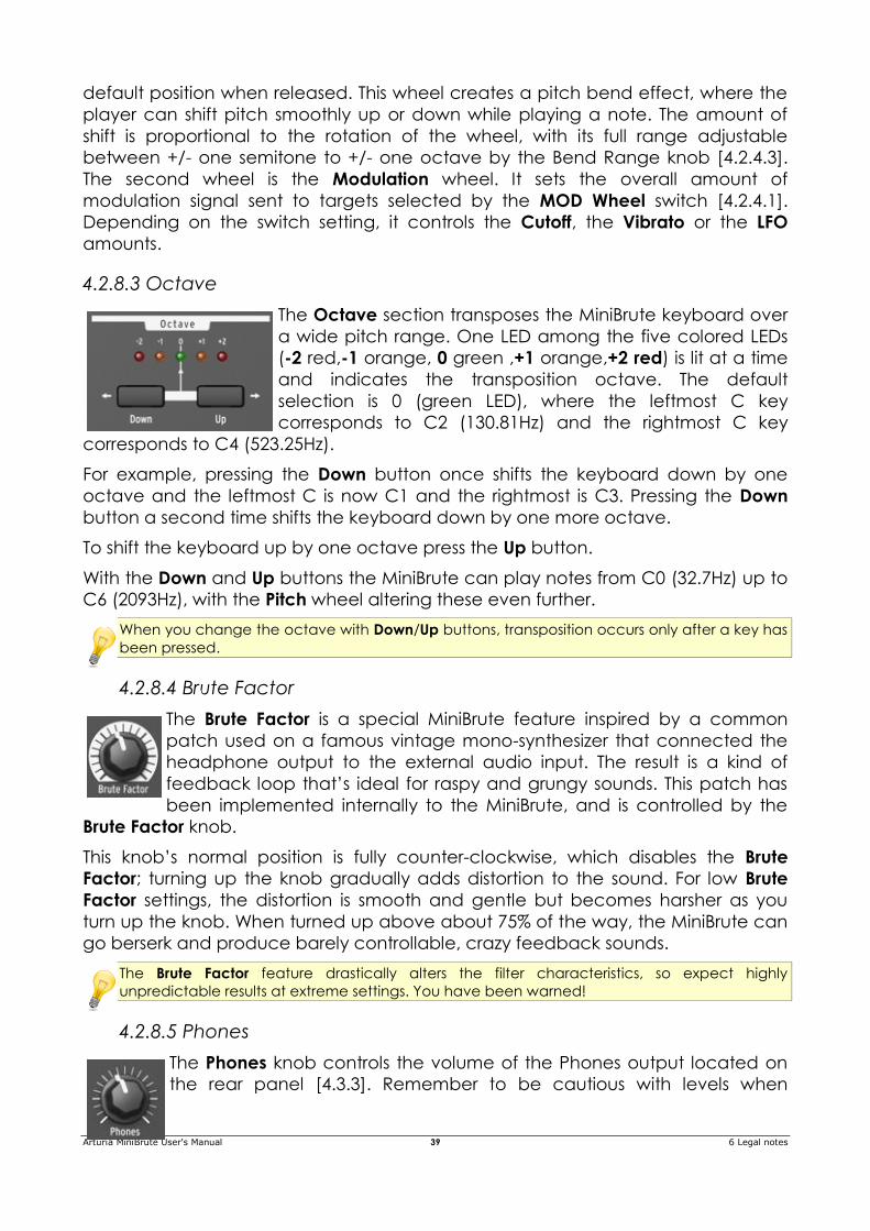
4.2.8.3 Octave
The Octave section transposes the MiniBrute keyboard over
a wide pitch range. One LED among the five colored LEDs
(-2 red,-1 orange, 0 green ,+1 orange,+2 red) is lit at a time
and indicates the transposition octave. The default
selection is 0 (green LED), where the leftmost C key
corresponds to C2 (130.81Hz) and the rightmost C key
corresponds to C4 (523.25Hz).
For example, pressing the Down button once shifts the keyboard down by one
octave and the leftmost C is now C1 and the rightmost is C3. Pressing the Down
button a second time shifts the keyboard down by one more octave.
To shift the keyboard up by one octave press the Up button.
With the Down and Up buttons the MiniBrute can play notes from C0 (32.7Hz) up to
C6 (2093Hz), with the Pitch wheel altering these even further.
When you change the octave with Down/Up buttons, transposition occurs only after a key has
been pressed.
4.2.8.4 Brute Factor
The Brute Factor is a special MiniBrute feature inspired by a common
patch used on a famous vintage mono-synthesizer that connected the
headphone output to the external audio input. The result is a kind of
feedback loop that’s ideal for raspy and grungy sounds. This patch has
been implemented internally to the MiniBrute, and is controlled by the
Brute Factor knob.
This knob’s normal position is fully counter-clockwise, which disables the Brute
Factor; turning up the knob gradually adds distortion to the sound. For low Brute
Factor settings, the distortion is smooth and gentle but becomes harsher as you
turn up the knob. When turned up above about 75% of the way, the MiniBrute can
go berserk and produce barely controllable, crazy feedback sounds.
The Brute Factor feature drastically alters the filter characteristics, so expect highly
unpredictable results at extreme settings. You have been warned!
4.2.8.5 Phones
The Phones knob controls the volume of the Phones output located on
the rear panel [4.3.3]. Remember to be cautious with levels when
Arturia MiniBrute User's Manual 40 6 Legal notes
listening through headphones.
4.2.8.6 Master Volume
The Master Volume knob sets the MiniBrute overall output volume, which
fits the standard +4dBu line level. To silence the MiniBrute, turn this knob
fully counter-clockwise.
4.2.8.7 Fine Tune
The Fine Tune knob provides precision adjustment of the oscillator pitch.
The 12 o'clock position corresponds to the default tuning (i.e. A=440Hz)
when you play the second rightmost A of the keyboard and the default
Octave [4.2.8.3] is selected. The full range of the Fine Tuning knob is from
about -2 semitones to +2 semitones. Fine-tuning makes it possible to tune
the MiniBrute to other instruments that are slightly out of tune.
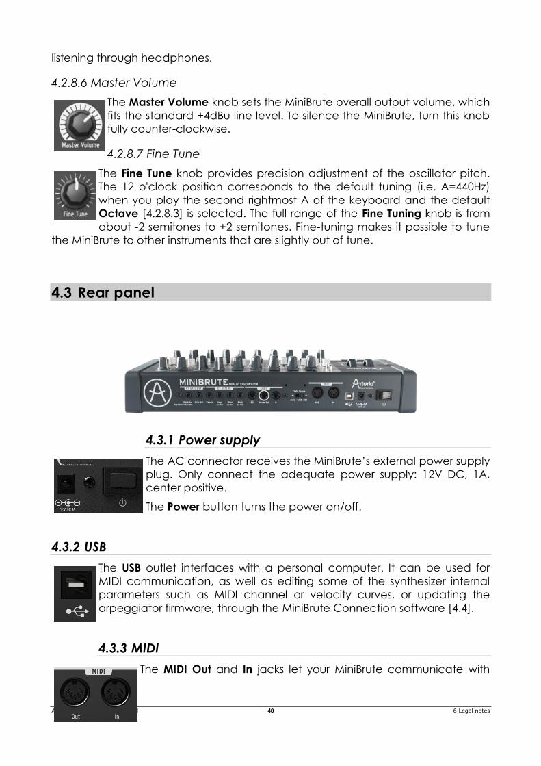
4.3 Rear panel
4.3.1 Power supply
The AC connector receives the MiniBrute’s external power supply
plug. Only connect the adequate power supply: 12V DC, 1A,
center positive.
The Power button turns the power on/off.
4.3.2 USB
The USB outlet interfaces with a personal computer. It can be used for
MIDI communication, as well as editing some of the synthesizer internal
parameters such as MIDI channel or velocity curves, or updating the
arpeggiator firmware, through the MiniBrute Connection software [4.4].
4.3.3 MIDI
The MIDI Out and In jacks let your MiniBrute communicate with
Arturia MiniBrute User's Manual 41 6 Legal notes
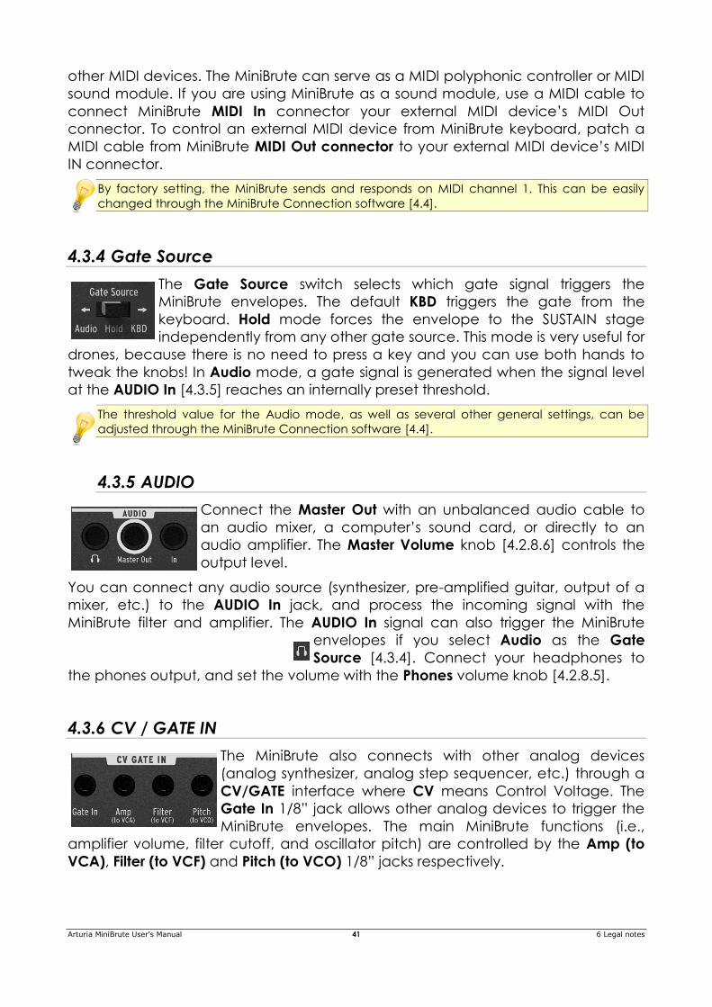
other MIDI devices. The MiniBrute can serve as a MIDI polyphonic controller or MIDI
sound module. If you are using MiniBrute as a sound module, use a MIDI cable to
connect MiniBrute MIDI In connector your external MIDI device’s MIDI Out
connector. To control an external MIDI device from MiniBrute keyboard, patch a
MIDI cable from MiniBrute MIDI Out connector to your external MIDI device’s MIDI
IN connector.
By factory setting, the MiniBrute sends and responds on MIDI channel 1. This can be easily
changed through the MiniBrute Connection software [4.4].
4.3.4 Gate Source
The Gate Source switch selects which gate signal triggers the
MiniBrute envelopes. The default KBD triggers the gate from the
keyboard. Hold mode forces the envelope to the SUSTAIN stage
independently from any other gate source. This mode is very useful for
drones, because there is no need to press a key and you can use both hands to
tweak the knobs! In Audio mode, a gate signal is generated when the signal level
at the AUDIO In [4.3.5] reaches an internally preset threshold.
The threshold value for the Audio mode, as well as several other general settings, can be
adjusted through the MiniBrute Connection software [4.4].
4.3.5 AUDIO
Connect the Master Out with an unbalanced audio cable to
an audio mixer, a computer’s sound card, or directly to an
audio amplifier. The Master Volume knob [4.2.8.6] controls the
output level.
You can connect any audio source (synthesizer, pre-amplified guitar, output of a
mixer, etc.) to the AUDIO In jack, and process the incoming signal with the
MiniBrute filter and amplifier. The AUDIO In signal can also trigger the MiniBrute
envelopes if you select Audio as the Gate
Source [4.3.4]. Connect your headphones to
the phones output, and set the volume with the Phones volume knob [4.2.8.5].
4.3.6 CV / GATE IN
The MiniBrute also connects with other analog devices
(analog synthesizer, analog step sequencer, etc.) through a
CV/GATE interface where CV means Control Voltage. The
Gate In 1/8” jack allows other analog devices to trigger the
MiniBrute envelopes. The main MiniBrute functions (i.e.,
amplifier volume, filter cutoff, and oscillator pitch) are controlled by the Amp (to
VCA), Filter (to VCF) and Pitch (to VCO) 1/8” jacks respectively.
Arturia MiniBrute User's Manual 42 6 Legal notes
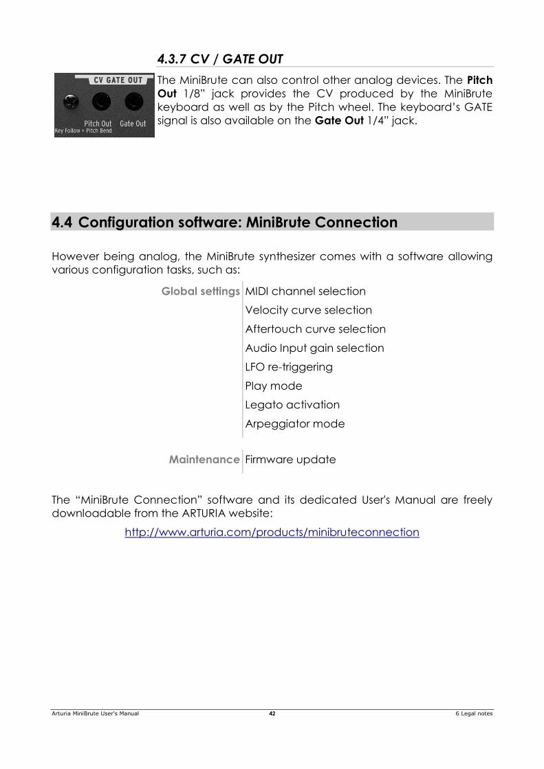
4.3.7 CV / GATE OUT
The MiniBrute can also control other analog devices. The Pitch
Out 1/8” jack provides the CV produced by the MiniBrute
keyboard as well as by the Pitch wheel. The keyboard’s GATE
signal is also available on the Gate Out 1/4” jack.
4.4 Configuration software: MiniBrute Connection
However being analog, the MiniBrute synthesizer comes with a software allowing
various configuration tasks, such as:
Global settings MIDI channel selection
Velocity curve selection
Aftertouch curve selection
Audio Input gain selection
LFO re-triggering
Play mode
Legato activation
Arpeggiator mode
Maintenance Firmware update
The “MiniBrute Connection” software and its dedicated User's Manual are freely
downloadable from the ARTURIA website:
http://www.arturia.com/products/minibruteconnection
Arturia MiniBrute User's Manual 43 6 Legal notes
5 USING YOUR MINIBRUTE
5.1 Let's create a basic sound
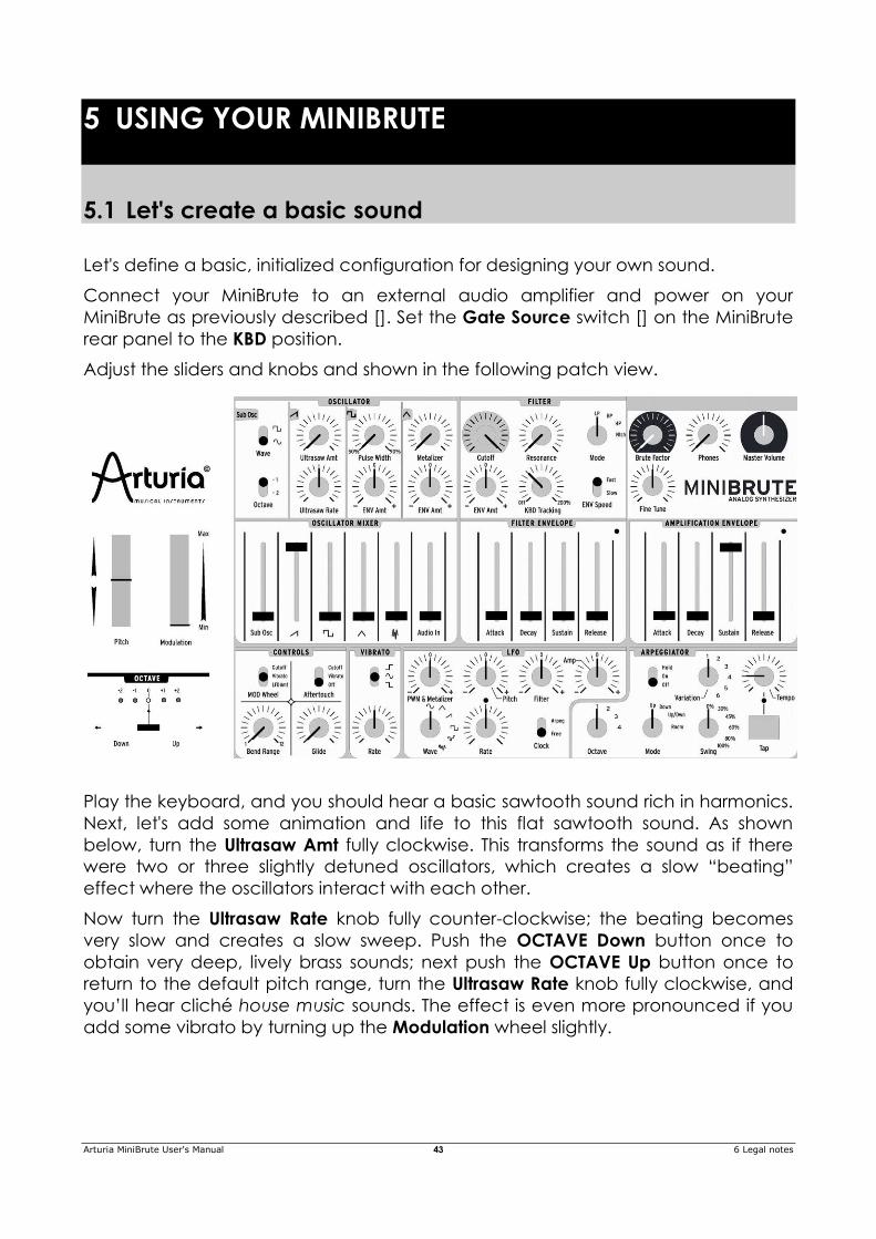
Let's define a basic, initialized configuration for designing your own sound.
Connect your MiniBrute to an external audio amplifier and power on your
MiniBrute as previously described []. Set the Gate Source switch [] on the MiniBrute
rear panel to the KBD position.
Adjust the sliders and knobs and shown in the following patch view.
Play the keyboard, and you should hear a basic sawtooth sound rich in harmonics.
Next, let's add some animation and life to this flat sawtooth sound. As shown
below, turn the Ultrasaw Amt fully clockwise. This transforms the sound as if there
were two or three slightly detuned oscillators, which creates a slow “beating”
effect where the oscillators interact with each other.
Now turn the Ultrasaw Rate knob fully counter-clockwise; the beating becomes
very slow and creates a slow sweep. Push the OCTAVE Down button once to
obtain very deep, lively brass sounds; next push the OCTAVE Up button once to
return to the default pitch range, turn the Ultrasaw Rate knob fully clockwise, and
you’ll hear cliché house music sounds. The effect is even more pronounced if you
add some vibrato by turning up the Modulation wheel slightly.
Arturia MiniBrute User's Manual 44 6 Legal notes
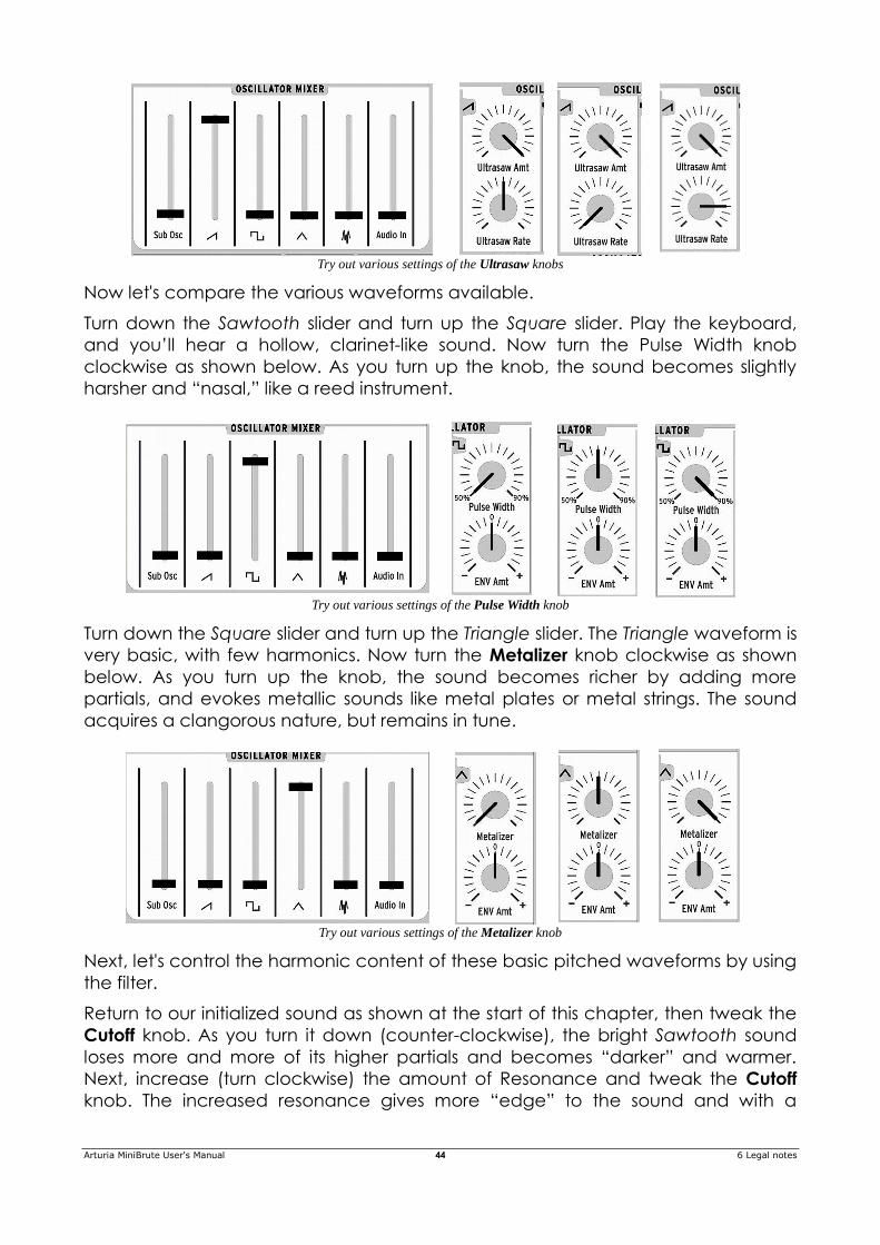
Try out various settings of the Ultrasaw knobs
Now let's compare the various waveforms available.
Turn down the Sawtooth slider and turn up the Square slider. Play the keyboard,
and you’ll hear a hollow, clarinet-like sound. Now turn the Pulse Width knob
clockwise as shown below. As you turn up the knob, the sound becomes slightly
harsher and “nasal,” like a reed instrument.
Try out various settings of the Pulse Width knob
Turn down the Square slider and turn up the Triangle slider. The Triangle waveform is
very basic, with few harmonics. Now turn the Metalizer knob clockwise as shown
below. As you turn up the knob, the sound becomes richer by adding more
partials, and evokes metallic sounds like metal plates or metal strings. The sound
acquires a clangorous nature, but remains in tune.
Try out various settings of the Metalizer knob
Next, let's control the harmonic content of these basic pitched waveforms by using
the filter.
Return to our initialized sound as shown at the start of this chapter, then tweak the
Cutoff knob. As you turn it down (counter-clockwise), the bright Sawtooth sound
loses more and more of its higher partials and becomes “darker” and warmer.
Next, increase (turn clockwise) the amount of Resonance and tweak the Cutoff
knob. The increased resonance gives more “edge” to the sound and with a
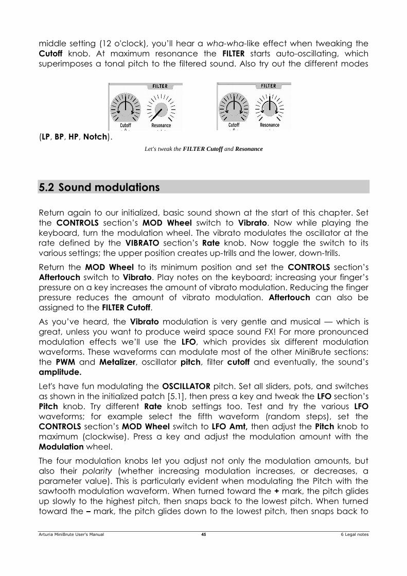
Arturia MiniBrute User's Manual 45 6 Legal notes
middle setting (12 o'clock), you’ll hear a wha-wha-like effect when tweaking the
Cutoff knob. At maximum resonance the FILTER starts auto-oscillating, which
superimposes a tonal pitch to the filtered sound. Also try out the different modes
(LP, BP, HP, Notch).
Let's tweak the FILTER Cutoff and Resonance
5.2 Sound modulations
Return again to our initialized, basic sound shown at the start of this chapter. Set
the CONTROLS section’s MOD Wheel switch to Vibrato. Now while playing the
keyboard, turn the modulation wheel. The vibrato modulates the oscillator at the
rate defined by the VIBRATO section’s Rate knob. Now toggle the switch to its
various settings; the upper position creates up-trills and the lower, down-trills.
Return the MOD Wheel to its minimum position and set the CONTROLS section’s
Aftertouch switch to Vibrato. Play notes on the keyboard; increasing your finger’s
pressure on a key increases the amount of vibrato modulation. Reducing the finger
pressure reduces the amount of vibrato modulation. Aftertouch can also be
assigned to the FILTER Cutoff.
As you’ve heard, the Vibrato modulation is very gentle and musical — which is
great, unless you want to produce weird space sound FX! For more pronounced
modulation effects we’ll use the LFO, which provides six different modulation
waveforms. These waveforms can modulate most of the other MiniBrute sections:
the PWM and Metalizer, oscillator pitch, filter cutoff and eventually, the sound’s
amplitude.
Let's have fun modulating the OSCILLATOR pitch. Set all sliders, pots, and switches
as shown in the initialized patch [5.1], then press a key and tweak the LFO section’s
Pitch knob. Try different Rate knob settings too. Test and try the various LFO
waveforms; for example select the fifth waveform (random steps), set the
CONTROLS section’s MOD Wheel switch to LFO Amt, then adjust the Pitch knob to
maximum (clockwise). Press a key and adjust the modulation amount with the
Modulation wheel.
The four modulation knobs let you adjust not only the modulation amounts, but
also their polarity (whether increasing modulation increases, or decreases, a
parameter value). This is particularly evident when modulating the Pitch with the
sawtooth modulation waveform. When turned toward the + mark, the pitch glides
up slowly to the highest pitch, then snaps back to the lowest pitch. When turned
toward the – mark, the pitch glides down to the lowest pitch, then snaps back to
Arturia MiniBrute User's Manual 46 6 Legal notes
the highest pitch.
Another important sound modulation source is the FILTER ENVELOPE. This provides
dynamic control over either the FILTER Cutoff, OSCILLATOR Pulse Width, or the
Metalizer harshness. The FILTER ENVELOPE amount and polarity are controlled by
the Env Amt knobs, which are very useful when you want to create lively sounds.
5.3 External sound processing
Plug your external audio source in the Audio In 1/8'' jack [] on the MiniBrute’s rear
panel. Your audio source must provide line level signals, so with electric guitar
you’ll need to patch a preamp or other processor (e.g., compressor, distortion,
multieffects) between the guitar and the Audio In. Adjust the OSCILLATOR MIXER’s
Audio In slider to the desired level.
When using an external audio input, select a GATE Source setting that corresponds
to how you want to process the external source.
To trigger the envelopes with the keyboard, set the GATE Source switch on
the MiniBrute’s rear panel to the KBD position.
To hear the external source continuously and process it, select the Hold
position.
To trigger the envelopes when the external signal level exceeds a fixed
threshold, select the Audio In position (you can change the threshold level
using the MiniBrute's software; see chapter 4.4.
The following setting produces an auto-wha effect combined with tremolo. The
Modulation wheel controls the amount of tremolo (make sure that the CONTROLS
section’s MOD Wheel switch is set to LFO Amt).
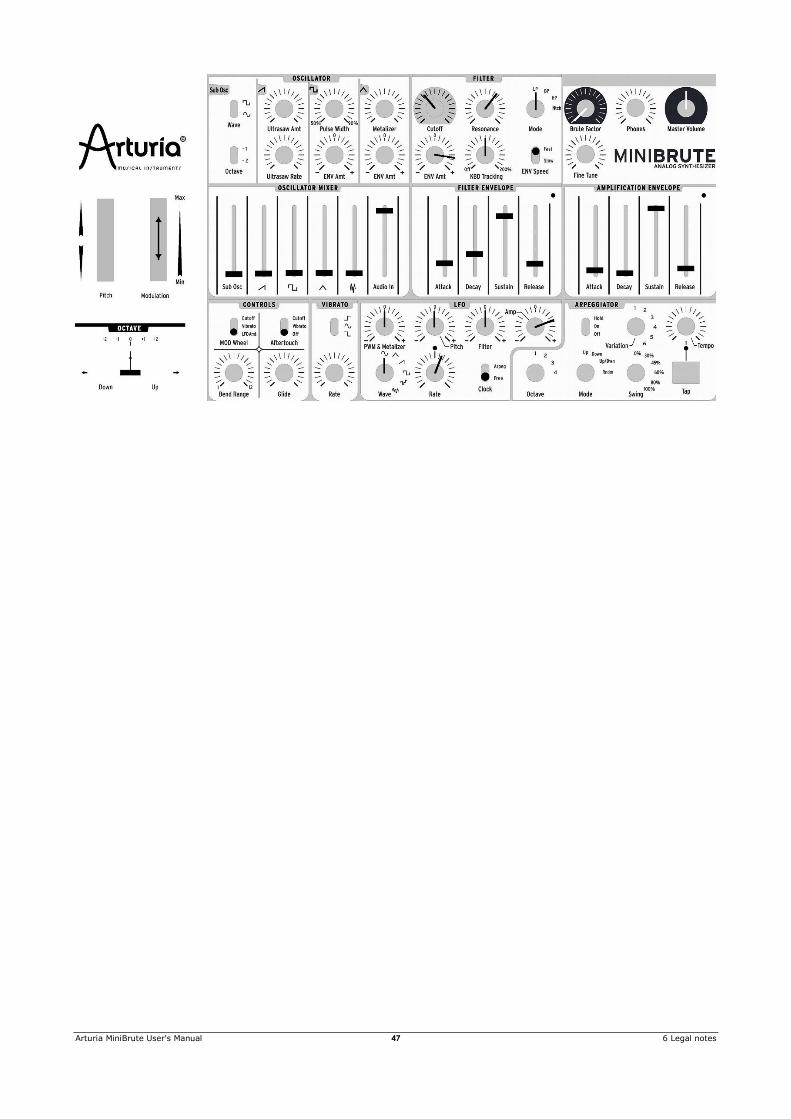
Arturia MiniBrute User's Manual 47 6 Legal notes
Arturia MiniBrute User's Manual 48 6 Legal notes
6 LEGAL NOTES
6.1 No liability for consequential damages
Neither ARTURIA nor anyone else involved in the creation, production, or delivery
of this product shall be liable for any direct, indirect, consequential, or incidental
damages arising out of the use of, or inability to use this product (including without
limitation, damages for loss of business profits, business interruption, loss of business
information and the like) even if ARTURIA was previously advised of the possibility of
such damages. Some states do not allow limitations on the length of an implied
warranty or the exclusion or limitation of incidental or consequential damages, so
the above limitation or exclusions may not apply to you. This warranty gives you
specific legal rights, and you may also have other rights which vary from state to
state.
6.2 FCC Information (USA)
DO NOT MODIFY THE UNIT! This product, when installed as indicate in the
instructions contained in this manual, meets FCC requirement. Modifications not
expressly approved by ARTURIA may avoid your authority, granted by the FCC, to
use the product.
IMPORTANT: When connecting this product to accessories and/or another
product, use only high quality shielded cables. Cable (s) supplied with this product
MUST be used. Follow all installation instructions. Failure to follow instructions could
void your FFC authorization to use this product in the USA.
NOTE: This product has been tested and found to comply with the limit for a Class B
Digital device, pursuant to Part 15 of the FCC rules. These limits are designed to
provide a reasonable protection against harmful interference in a residential
environment. This equipment generate, use and radiate radio frequency energy
and, if not installed and used according to the instructions found in the users
manual, may cause interferences harmful to the operation to other electronic
devices. Compliance with FCC regulations does not guarantee that interferences
will not occur in all the installations. If this product is found to be the source of
interferences, which can be determined by turning the unit “OFF” and “ON”,
please try to eliminate the problem by using one of the following measures:
Relocate either this product or the device that is affected by the
interference.
Use power outlets that are on different branch (circuit breaker or fuse)
circuits or install AC line filter(s).
Arturia MiniBrute User's Manual 49 6 Legal notes
In the case of radio or TV interferences, relocate/ reorient the antenna. If the
antenna lead-in is 300 ohm ribbon lead, change the lead-in to coaxial
cable.
If these corrective measures do not bring any satisfied results, please the
local retailer authorized to distribute this type of product. If you cannot
locate the appropriate retailer, please contact ARTURIA.
The above statements apply ONLY to those products distributed in the USA.
6.3 Canada
NOTICE: This class B digital apparatus meets all the requirements of the Canadian
Interference-Causing Equipment Regulation.
AVIS: Cet appareil numérique de la classe B respecte toutes les exigences du
Règlement sur le matériel brouilleur du Canada.
6.4 Europe
This product complies with the requirements of European Directive
89/336/EEC.


![[EN] Analog Lab - User's Manual 20141113 - Arturia · PDF file6 ARTURIA – Analog Lab – USER’S MANUAL 1 INTRODUCTION ... In 2012 Arturia launched its first venture into the classic](https://static.fdocuments.us/doc/165x107/5a72da397f8b9aac538dfd9a/en-analog-lab-users-manual-20141113-arturia-6-arturia-analog-lab.jpg)

