Mine shafts and winding systems · sinking winding systems, emergency egress winding systems,...
90
Mine shafts and winding systems NSW Code of Practice | WHS legislation
Transcript of Mine shafts and winding systems · sinking winding systems, emergency egress winding systems,...
Mine shafts and winding systems NSW Code of Practice | WHS legislation
1 NSW Resources Regulator
Mine shafts and winding systems NSW Code of Practice | WHS Legislation
Document control Published by NSW Department of Planning and Environment, NSW Resources Regulator
Title: NSW Code of Practice: Mine shafts and winding systems
First published: February 2019
Authorised by: Chief Inspector
CM9 reference: DOC18/671295
Amendment schedule
Date Version Amendment
© State of New South Wales through the NSW Department of Planning and Environment 2018.
This publication is copyright. You may download, display, print and reproduce this material in an unaltered form only (retaining this notice) for your personal use or for non-commercial use within your organisation. To copy, adapt, publish, distribute or commercialise any of this publication you will need to seek permission from the NSW Department of Planning and Environment.
Disclaimer: The information contained in this publication is based on knowledge and understanding at the time of writing (February 2019). However, because of advances in knowledge, users are reminded of the need to ensure that information upon which they rely is up to date and to check currency of the information with the appropriate officer of the NSW Department of Planning and Environment or the user’s independent advisor.
2 NSW Resources Regulator
Mine shafts and winding systems Code of Practice | WHS legislation
Foreword This NSW Code of Practice: Mine shafts and winding systems is an approved code of practice under section 274 of the Work Health and Safety Act 2011 (WHS Act).
An approved code of practice is a practical guide to achieving the standards of health, safety and welfare required under the WHS Act, Work Health and Safety Regulation 2017 (WHS Regulations), Work Health and Safety (Mines and Petroleum Sites) Act 2013 (WHS (MPS) Act) and the Work Health and Safety (Mines and Petroleum Sites) Regulation 2014 (WHS (MPS) Regulations).1
A code of practice applies to anyone who has a duty of care in the circumstances described in the code. In most cases, following an approved code of practice would achieve compliance with the health and safety duties in the WHS laws, in relation to the subject matter of the code. Like regulations, codes of practice deal with particular issues, but do not cover all hazards or risks that may arise. The health and safety duties require duty holders to consider all risks associated with work, not only those for which regulations and codes of practice exist.
Codes of practice are admissible in court proceedings under the WHS laws. Courts may regard a code of practice as evidence of what is known about a hazard, risk or control and may rely on the code in determining what is reasonably practicable in the circumstances to which the code relates.
Compliance with the WHS laws may be achieved by following another method, such as a technical or industry standard, if it provides an equivalent or higher standard of work health and safety than the code.
An inspector may refer to an approved code of practice when issuing an improvement or prohibition notice.
The development of this code of practice This code of practice has been developed under the ‘Inter-Governmental Agreement for Consistency or Uniformity of Mine Safety Legislation and Regulations in NSW, Queensland and Western Australia’ and forms part of the mining safety legislative framework for these states. Under this agreement, tri-state model legislation was developed, although designed to be structured and customised differently in each of these states.
This code was also developed in consultation with the Non-Core (tri-state) Legislative Working Group representing the following stakeholders from the mining industry in the tri-states including:
• Construction, Forestry, Mining and Energy Union (CFMEU) – NSW and Queensland • NSW Minerals Council • NSW Department of Planning and Environment, Resources Regulator
1 It will sometimes be convenient to refer generally to ‘WHS laws’, which includes:
• WHS Act • WHS (MPS) Act • WHS Regulations • WHS (MPS) Regulations
3 NSW Resources Regulator
Mine shafts and winding systems Code of Practice | WHS legislation
• Queensland Resources Council • Queensland Department of Natural Resources and Mines • Western Australian Chamber of Minerals and Energy • Western Australia Department of Mines and Petroleum
The following organisations with technical expertise relevant to winding systems participated in the group:
• HIMA Australia Pty Ltd • ABB
The Non-Core (tripartite) Legislative Working Group endorsed this tri-state model code on 19 November 2014. Accordingly, this NSW version of the code of practice is based on the Non-Core (tripartite) Legislative Working Group endorsed tri-state model code. The code will be reviewed as required or when legislation is reviewed.

4 NSW Resources Regulator
Mine shafts and winding systems Code of Practice | WHS legislation
Contents The development of this code of practice ........................................................................................... 2
Scope and application ............................................................................................................................ 7
How to use this code of practice ......................................................................................................... 7
Acronyms ............................................................................................................................................ 8
Key terms ............................................................................................................................................ 9
1. Introduction ....................................................................................................................................... 11
1.1. What are mine shafts and winding systems? ............................................................................. 12
1.2. Who has duties relating to mine shafts and winding systems? .................................................. 13
1.3. What must be included in the PHMP for mine shafts and winding systems .............................. 14
1.3.1. Mandatory considerations ................................................................................................... 14
1.3.2. Mandatory – specific risk controls ....................................................................................... 14
1.4. What consultation is required for the PHMP .............................................................................. 17
1.5. Other duties in relation to plant (winding systems) .................................................................... 17
1.5.1. Management or control of plant ........................................................................................... 17
1.5.2. Design, manufacture, import, supply ................................................................................... 18
1.5.3. Calculation, analysis testing or examination ....................................................................... 18
1.5.4. Information to be provided ................................................................................................... 18
1.5.5. Install, construct or commission plant ................................................................................. 19
1.5.6. Supply of second-hand plant ............................................................................................... 19
1.6. Interaction of PHMP with other plans ......................................................................................... 19
2. Managing Risk .................................................................................................................................. 20
2.1. General requirements ................................................................................................................ 21
2.2. Hazard identification .................................................................................................................. 23
2.3. Assessment of risks ................................................................................................................... 26
2.3.1. Investigation and analysis methods .................................................................................... 27
2.3.2. Assessing the individual and cumulative effects ................................................................. 27
2.4. Control of risks ........................................................................................................................... 28
2.4.1. Specific controls .................................................................................................................. 28
2.4.2. Hierarchy of controls ........................................................................................................... 28
2.5. Maintenance of control measures .............................................................................................. 30
2.6. Review of control measures ....................................................................................................... 30
3. Content of the PHMP – Mine shafts and winding systems ............................................................... 31
3.1. General ...................................................................................................................................... 31
5 NSW Resources Regulator
Mine shafts and winding systems Code of Practice | WHS legislation
3.2. PHMP: additional matters to be considered ............................................................................... 35
4. Mandatory risk control measures – mine winding systems .............................................................. 41
4.1. Specific risk controls – WHS ...................................................................................................... 41
4.1.1. Winding systems ................................................................................................................. 41
4.1.2. Ropes .................................................................................................................................. 49
4.1.3. Operation of shaft conveyances .......................................................................................... 50
4.2. Other specific risk controls – WHS regulations .......................................................................... 51
4.3. Registration of winding systems ................................................................................................ 54
5. Life cycle management ..................................................................................................................... 55
5.1. Design ........................................................................................................................................ 56
5.2. Manufacture ............................................................................................................................... 57
5.3. Installation .................................................................................................................................. 57
5.4. Commissioning .......................................................................................................................... 58
5.5. Operation ................................................................................................................................... 58
5.6. Installation, testing and maintenance ......................................................................................... 58
5.7. Life cycle documentation – plant safety file ............................................................................... 59
6. Monitoring, periodic review and audit ............................................................................................... 60
6.1. Monitoring .................................................................................................................................. 60
6.2. Review of control measures ....................................................................................................... 61
6.3. Periodic review ........................................................................................................................... 61
6.4. Audit ........................................................................................................................................... 63
Appendix A – Codes / engineering / technical standards ..................................................................... 65
NSW Codes of Practice .................................................................................................................... 65
Documents that from part of this code .............................................................................................. 65
Appendix B – Other useful information ................................................................................................. 69
Documents that do not form part of this code ................................................................................... 69
Appendix C – Rope factor of safety (FOS) ........................................................................................... 73
Rope breaking force .......................................................................................................................... 73
Drift drum winder rope FOS – transport of people ............................................................................ 73
Vertical shaft drum winder rope FOS ................................................................................................ 73
Friction winder head rope FOS ......................................................................................................... 74
Head ropes ....................................................................................................................................... 75
Friction winder balance rope FOS .................................................................................................... 75
Guide ropes and rubbing ropes ........................................................................................................ 75
Appendix D – Sample manual signals code for winding operations ..................................................... 76
6 NSW Resources Regulator
Mine shafts and winding systems Code of Practice | WHS legislation
Appendix E – Functional safety and application to winding systems ................................................... 78
Introduction ....................................................................................................................................... 78
Implementation and responsibility ..................................................................................................... 78
Generate a functional safety management plan (FSMP) .................................................................. 79
Analysis phase .................................................................................................................................. 79
Specification phase ........................................................................................................................... 79
Realisation/design ............................................................................................................................. 79
Verification and validation ................................................................................................................. 80
Functional safety assessment ........................................................................................................... 80
Operation and maintenance .............................................................................................................. 80
Consideration of functional safety for a winding system ................................................................... 81
Appendix F – Typical potential hazards, consequences and controls .................................................. 83
Appendix G – Sample fault tree analysis .............................................................................................. 87
7
Mine shafts and winding systems Code of Practice | WHS legislation
NSW Resources Regulator
Scope and application This code of practice provides guidance to assist mine operators in developing and implementing a principal hazard management plan (PHMP) for mine shafts and winding systems, as required under the WHS laws. The PHMP provides the means by which the mine operator will manage any risks associated with mine shafts and winding systems. These risks arise from hazards associated with gravity and kinetic energy and they are additional to other hazards associated with plant and structures. Note: Guidance on other hazards associated with plant and structures can be found in the NSW Code of Practice: Mechanical Engineering Control Plan and the NSW Code of Practice: Electrical Engineering Control Plan. This code may also be used by other duty holders such as contractors and businesses involved in the design, manufacture, installation, commissioning, operation, maintenance and discard (life cycle) of mine shafts and winding systems. This code applies to all mine shafts and winding systems in underground mines, including shaft sinking winding systems, emergency egress winding systems, people and material winding systems and material winding systems where people may be lifted (e.g. for shaft inspections or winding system maintenance). This code does not apply to the following types of mines under clause 184 of the WHS (MPS) Regulations, as they are not required to have a PHMP:
• an opal mine
• an underground small gemstone mine (see definitions in clause 3 of the WHS (MPS) Regulations)
• a tourist mine This code is not intended to apply to winding systems that do not lift people.
How to use this code of practice This code includes references to both mandatory and non-mandatory actions. The references to legal requirements contained in the WHS Act and Regulations, and the WHS (MPS) Act and Regulations are not exhaustive and are included for context only. This code has been prepared to be consistent with the WHS laws as at the date of publication and should be interpreted, to the extent that there is any ambiguity, in a manner that is consistent with the WHS laws. To ensure you comply with your legal obligations you must refer to the latest legislation, which is available on the NSW legislation website (www.legislation.nsw.gov.au). This publication does not represent a comprehensive statement of the law as it applies to particular problems or to individuals or as a substitute for legal advice. You should seek independent legal advice if you need assistance on the application of the law to your situation.
8
Mine shafts and winding systems Code of Practice | WHS legislation
NSW Resources Regulator
References to publications in the code are to be assumed to be the current version of the document. For example, Australian Standards are referred to without a year or amendment number so they are the current version. You should check whether this requires compliance with the standard as per the year specified, or as amended from time to time. See Appendix A for further details. The words ‘must’, ‘requires’ or ‘mandatory’ indicate that legal requirements exist and must be complied with. The word ‘should’ indicates a recommended course of action, while ‘may’ indicates an optional course of action. Unless otherwise indicated in the text, lists of points in the code should not be read as exhaustive. Every process developed, or document prepared for a mine should be developed to suit the nature, complexity and location of the particular mining operation and the risks associated with that mining operation.
Acronyms AS – Australian Standard (produced by Standards Australia)
AS/NZS – Australian and New Zealand Standard
ALARP – As Low As is Reasonably Practicable
EECP – Electrical Engineering Control Plan
FEA – Failure Effects Analysis
FMECA – Failure Modes Effects Criticality Analysis
FOS – Factor of Safety
LOPA – Layers of Protection Analysis
MDG – Mining Design Guideline
MECP – Mechanical Engineering Control Plan
NDT – Non-Destructive Testing
PH – Principal Hazard
PHMP – Principal Hazard Management Plan
PCBU - Person Conducting a Business or Undertaking
PCP – Principal Control Plan
SMS – Safety Management System
TARP – Trigger Action Response Plan
WHS – Work Health and Safety
WRAC – Workplace Risk Assessment Control
9
Mine shafts and winding systems Code of Practice | WHS legislation
NSW Resources Regulator
Key terms Arrestor system – an assembly, incorporating one or more arrestors, for decelerating and stopping the conveyance(s) within a winding system. Birdcage - where slack rope through torsional effects will lead to the rope tangling, giving appearance of a birdcage. Chairing or keps - supporting of a conveyance to be stationary by means other than the winding ropes or gripper system (Source: draft NSW MDG 33.1 Guidelines for the design, commissioning and maintenance of drum winders - General requirements). Competent person - a person who has acquired through training, qualification or experience the knowledge and skills to carry out the task. In the following circumstances, a competent person means: for design verification under clause 252 of the WHS Regulations, a person who has the skills, qualifications, competence and experience to design the plant or verify the design (Source: Clause 5(1) of the WHS Regulations). for inspection of plant for item registration purposes, a person who has: educational or vocational qualifications in an engineering discipline relevant to the plant being inspected, or knowledge of the technical standards relevant to the plant being inspected (Source: Clause 267 of the WHS Regulations) (Source: GNC-005 Guidance Note – Registration of Plant Designs and GNC-006 Guidance Note – Plant Item Registration) Conveyance – refers to any car, carriage, cage, skip, kibble, counterweight, or stage in which persons, minerals or materials are wound through a shaft. Counterweight – means a weight used to balance the weight of a conveyance on a friction winder. Drift winder – means a drum winder typically used in a mine adit for the transport of men and materials on slopes (drifts) of 10 to 30 degrees. Commonly used in coal mines. Drum winder – a shaft or drift winding system in which conveyances are raised and lowered by means of a single rope attached directly and winding onto a cylindrical drum, or drums in the case of double drum winding system. Fail safe - means a state or condition where, if any component or function of the plant fails, a system exists to prevent any increase in the risks. For example, if the primary drum brake fails, the secondary brake will prevent uncontrolled mechanical stopping of the winding system. However, once the secondary brake is engaged, a lower level of safety has been reached. The situation should be made safe and the fault rectified so that the fail-safe capability is re-established. Friction winder – a shaft winding system in which conveyances are raised and lowered by means of multiple ropes passing over a driving sheave, such that the driving force is transmitted from the sheave to the ropes by friction.
10
Mine shafts and winding systems Code of Practice | WHS legislation
NSW Resources Regulator
Inspection – an organised examination or formal evaluation exercise. In engineering, inspection involves measurement, tests and gauges to assess an object or activity where the results are to be compared with specific requirements or standards (source: NSW Code of practice: Mechanical Engineering Control Plan). Keps – see meaning of ‘chairing’ above Mine shaft and winding system - a winding system with all the additional factors that will influence risks associated with the operation of the winding system. For example, the influence of shaft drainage, shaft condition, mine ventilation and emergency use. See the meaning of ‘winding system’ below. Overwind - unintentional travel of a conveyance beyond its normal operating limits. Note: In practical terms this would mean the conveyance has gone past the normally intended limit of travel. This may also be referred to as over travel. Overwind safety catch system - a system of devices mounted in the headframe and on the conveyance to prevent the conveyance from falling an excessive distance after the conveyance has been brought to rest after being overwound. Rope slip - applies to friction winding systems where the rope(s) slips on the drive drum. Safety critical system – means a risk management control system whose failure potentially leads to a serious bodily injury or death. Shaft – in underground workings means a mine heading. A shaft maybe orientated from 0 to 90 degrees. Note: Section 4 of the WHS Act defines ‘structure’ to include shaft. Clause 3(1) of the WHS (MPS) Regulations states ‘shaft’ includes a drift. Trigger Action Response Plan (TARP) – a plan designed to prevent a risk from escalating by identifying potential indicators, to the hazard, assigning a hierarchy of alarms, or trigger levels, to each potential indicator, and specifying responses for each trigger level. Unsafe balance rope conditions - are those circumstances where the balance rope is operating outside design limitations. Uncontrolled movement - is a movement of the winding system which is unexpected and is not within the design specifications of the winding system for operation. Unsafe speed – is any speed which is not within the winding system specification. Winding system – means any plant (other than a portable winch or plant that is manually operated) that is used in a shaft to lift a person to or from an underground mine or between levels in an underground mine (regardless of whether it is used exclusively for that purpose). Source: Clause 3(1) of the WHS (MPS) Regulations.
11
Mine shafts and winding systems Code of Practice | WHS legislation
NSW Resources Regulator
1. Introduction Mine shafts and winding systems are important items of infrastructure in underground mines and there are many installations operating throughout the Australian mining industry. Failure of mine shafts and winding systems may result in serious injuries, deaths and equipment damage within the winding system constraints. A winding system not being available for operation when a mine emergency occurs may hinder the response at the mine and contribute to injury and/or death of underground workers. Winding system installations consist of many variations, such as:
• Shafts - examples include, lined to unlined shafts through a range of geological conditions; shafts of 1.5 metres to greater than 7 metres in diameter; shafts with no services; shafts with fire water, pump water, compressed air lines, electrical power cables, communication cables, gas monitoring lines, water control rings; upcast shafts in returns with ventilation, and intake downcast shafts.
• Types - examples include, single drum vertical shaft, double drum vertical shaft, drift slope haulage, single rope friction, multi-rope friction, rack and pinion.
• Uses – examples include, bulk material haulage, people, people and plant, shaft sinking (stage and personal conveyance), second means of egress and emergency escape
• Depths – distances of 30 metres to greater than 1500 metres in a single lift with multiple landings and different levels.
Mine winding systems that carry people are considered high risk plant, the failure of which has potential for multiple deaths. Some winding systems may carry more than 150 people in a single lift. The high-risk nature of winding systems is recognised in the WHS (MPS) Regulations by requiring specific control measures and a PHMP if it is identified as a principal hazard (PH). This code assists in identifying and controlling those hazards that may cause harm to people from mine shafts and winding systems. The nature of hazards associated with winding systems in mine shafts (as part of winding operations) have resulted in the publication of detailed information and control measures in documents such as standards, accident reports and guidance material. Common areas where serious injury and/or death have occurred in the past include:
• loss of control of the conveyance against the effects of gravity or kinetic energy • fall of materials and components down the shaft that either impact with the conveyance or
people below • fall of people down the shaft when carrying out installation, inspection, testing and
maintenance activities • parts of people extending out of the conveyance and colliding with a fixed object or
conveyance counterweight. Given the benefits of safely operating winding systems and the WHS laws, the mine operator should ensure they allocate sufficient resources to manage this type of plant. This will be assisted by a documented PHMP for the life cycle of the winding system, which includes competent people, work time to complete the various activities and appropriate mine infrastructure and facilities.
12
Mine shafts and winding systems Code of Practice | WHS legislation
NSW Resources Regulator
1.1. What are mine shafts and winding systems? Winding systems include any plant (other than a portable winch or a manually operated plant) used in mine shafts to lift people to and from or between levels in an underground mine.
WHS (MPS) Regulations 3 Definitions … shaft includes a drift. … winding system means any plant (other than a portable winch or plant that is manually operated) that is used in a shaft to lift a person to or from an underground mine or between levels at an underground mine (regardless of whether it is used exclusively for that purpose).
The following information may assist with understanding this definition of winding systems: a) Lift (or convey) people includes lifting people who may be inspecting, testing or maintaining
the winding system or the shaft. For example, although some haulage winding systems do not normally lift people, the winding systems may lift people to carry out inspections, tests and maintenance on the winding system itself, the shaft or the shaft sump.
b) Light portable winches are small scale winches that are not permanently installed. For example, small scale may include winches on vehicles and ‘a frame’ tripod portable hoists.
c) Winding systems used solely for lifting bulk materials or other equipment (such as, self-tipping kibbles and winches that lift equipment pipes) and do not lift people at any time, are regulated under the general plant requirements in the WHS laws.
d) Winding systems include the use of a crane to lower or raise people in a mine shaft (Note: the regulator and/or the PCBU may apply special conditions to these arrangements).
e) Winding systems include lifting people from the surface to the underground parts of the mine and between levels within the underground mine (including lifting people to and from the sump of the shaft with any associated attachments).
13
Mine shafts and winding systems Code of Practice | WHS legislation
NSW Resources Regulator
1.2. Who has duties relating to mine shafts and winding systems?
The mine operator must identify whether the mine has a PH in relation to mine shafts and winding systems, and if so, must prepare and implement a PHMP for each PH.
WHS (MPS) Regulations 5 Meaning of principal hazard (cl 612 model WHS Regs) In this Regulation, a principal hazard is any activity, process, procedure, plant, structure, substance, situation or other circumstance relating to the carrying out of: (a) mining operations that have a reasonable potential to result in multiple deaths in a single
incident or a series or recurring incidents in relation to any of the following: … (iii) mine shafts and winding systems, …
23 Identification of principal hazards and conduct of risk assessments (cl 627 model WHS Regs) (1) The operator of a mine or petroleum site must identify all principal hazards associated with mining operations or petroleum operations at the mine or petroleum site. (details of penalty omitted)
… 24 Preparation of principal hazard management plan (cl 628 model WHS Regs) (1) The operator of a mine or petroleum site must prepare a principal hazard management plan for each principal hazard associated with mining operations or petroleum operations at the mine or petroleum site in accordance with this clause and Schedule 1. (details of penalty omitted) …
In practice, all winding systems that carry more than one person have the potential to result in multiple deaths in a single incident. Historically, the operation of mine winding systems has resulted in a series of recurring single death incidents, for example, from people extending parts of their body outside the conveyance. When developing the PHMP for mine shafts and winding systems, it is important that the relevant technical matters are understood and taken into account. This will require a competent person who can provide suitable technical advice in the appropriate fields (e.g. mechanical, electrical, hydraulics, control systems, geo-technical, structural, ventilation).
14
Mine shafts and winding systems Code of Practice | WHS legislation
NSW Resources Regulator
1.3. What must be included in the PHMP for mine shafts and winding systems
1.3.1. Mandatory considerations Clauses 23, 24 and Schedule 1 clause 3 of the WHS (MPS) Regulations set out what must be considered when developing PHMPs relating to mine shafts and winding systems. Refer to Chapter 3 Content of the PHMP – Mine Shafts and Winding Systems for further guidance.
WHS (MPS) Regulations Schedule 1 Principal hazard management plans—additional matters to be considered (Sch 19 model WHS Regs) 3 Mine shafts and winding systems The following matters must be considered in developing the control measures to manage the risks associated with mine shafts and winding systems: (a) the potential for instability and loss of integrity of the shaft, (b) the potential for fires in underground operations, the shaft or winder areas, (c) the potential for any unintended or uncontrolled movement of conveyances within the shaft, (d) the potential for a conveyance to fall down the shaft, (e) the potential for failure of, or damage to, equipment and control measures, including the following:
(i) control measures that are intended to prevent any shaft conveyance from overwind, excessive acceleration or deceleration, unsafe or excessive speeds or uncontrolled movement,
(ii) control measures that are intended to detect the presence of slack rope, drum slip conditions or unsafe tail rope conditions,
(iii) braking systems and systems performing an equivalent function that are intended to ensure that the winder remains under control,
(iv) warning systems that are intended to alert persons at the mine to any emergency in a winding system,
(v) communication systems, (f) the potential for injury to a person from:
(i) material being carried in a conveyance with the person, or (ii) material falling from a conveyance, or (iii) the person falling from a conveyance, or (iv) a part of the person extending out of the conveyance,
(g) provision for the emergency exit of persons from a conveyance.
1.3.2. Mandatory – specific risk controls
15
Mine shafts and winding systems Code of Practice | WHS legislation
NSW Resources Regulator
Clause 47 (Winding systems), clause 48 (Ropes) and clause 49 (Operation of shaft conveyances) of the WHS (MPS) Regulations set out mandatory risk control measures that the mine operator must comply with, if the mine uses mines shafts or winding systems. Chapter 4 of this code provides guidance on these mandatory risk controls. Note: these mandatory risk controls apply even if the mine operator has not identified the mine shaft and winding system to be a principal hazard (PH). The exception only applies to mine operators of opal mines, underground small gemstone mines and tourist mines.
WHS (MPS) Regulations
47 Winding systems (cl 644 model WHS Regs)
(1) The mine operator of an underground mine (other than an opal mine) must ensure that every winding system used or that may be put into use at the mine includes the following: (a) ropes and devices that can withstand all forces reasonably expected to be borne by the ropes and devices, (b) control measures to prevent, so far as is reasonably practicable, any shaft conveyance from overwind, moving at an unsafe speed, excessive acceleration and deceleration and uncontrolled movement, (c) at least 2 braking (or equivalent) systems that ensure the winder remains under control in the event of a failure in any one of the systems, (d) control measures that detect any of the following malfunctions that may be present:
(i) slack rope, (ii) rope slip, (iii) unsafe balance rope conditions, (iv) unsafe coiling of rope,
(e) control measures that cause the winder to be bought to a safe state when a condition or malfunction referred to in paragraph (d) is detected, (f) warning systems to alert persons at the mine to any emergency in a winding system, (g) if it is reasonably practicable, remote monitoring of the functions of the system, (h) an effective means of communication:
(i) between the surface and any shaft conveyance used for carrying persons, and (ii) between the point of control of the winder and the entry to every shaft that is in use, and
(i) a device that safely attaches ropes to conveyances, (j) in the case of multi-rope winders—devices that load the ropes as uniformly as
possible. (details of penalty omitted)
16
Mine shafts and winding systems Code of Practice | WHS legislation
NSW Resources Regulator
48 Ropes The mine operator of an underground mine (other than an opal mine) must ensure that: (a) each rope used for the purposes of a winding system or slope haulage is regularly inspected and tested to ensure that it is safe for that use, and (b) criteria are established to determine when a rope is no longer suitable for any such use. (details of penalty omitted)
49 Operation of shaft conveyances (cl 645 model WHS Regs) (1) In this clause: shaft conveyance means a conveyance that is connected to a winding system. (2) The mine operator of an underground mine must ensure that material or plant being carried in a shaft conveyance: (a) does not protrude from the shaft conveyance while it is moving so as to contact a wall of the shaft or anything in the shaft, and (b) is so secured to the shaft conveyance that it cannot leave the shaft conveyance except by being deliberately removed. (details of penalty omitted) (3) The mine operator of an underground mine must ensure that persons being carried in a shaft conveyance are adequately protected from another shaft conveyance in the same shaft, from any material or plant being carried by the other shaft conveyance and from the wall of the shaft or anything in the shaft. (details of penalty omitted) (4) The mine operator of an underground mine must ensure that, if a shaft conveyance that combines a cage and skip is used, material is not carried in the skip while persons are being carried in the cage. (details of penalty omitted) (5) The mine operator of an underground mine must ensure that control measures are implemented to prevent a shaft conveyance from falling down the shaft. (details of penalty omitted) (6) The mine operator of an underground mine must ensure, so far as is reasonably practicable, that control measures are implemented to prevent persons, rock, material and plant from falling down a shaft. (details of penalty omitted)
17
Mine shafts and winding systems Code of Practice | WHS legislation
NSW Resources Regulator
1.4. What consultation is required for the PHMP The mine operator has a duty to consult with workers on matters that relate to work health and safety that are or likely to be directly affected (section 47 WHS Act), which includes the PHMP for mine shafts and winding systems. This involves implementing a safety role for workers to consider control measures for risks to be managed under the principal control plans. It also involves consulting with workers in conducting risk assessments for the principal control plans (clauses 120 and 121 WHS (MPS) Regulations). It may also involve consulting with any safety committee at the mine. The mine operator must, so far as is reasonably practicable, consult, cooperate and coordinate with other persons who also have a duty in relation to the risks associated with the mechanical aspects of plant and structures at the mine. This includes PCBUs and their workers (sections 46 and 47 WHS Act). Consultation, coordination and cooperation between the mine operator and other PCBUs, especially contractors, is critical in ensuring that all risks associated with the mechanical aspects of plant and structures are identified and managed in a consistent way. General guidance on the duty to consult under the WHS Act can be found in the NSW Code of Practice: Work health and safety consultation, cooperation and coordination and for mines specifically the NSW Code of Practice: Safety management systems in mines.
1.5. Other duties in relation to plant (winding systems) The mine operator (as well as any other PCBUs at a mine) has a primary duty under section 19 of the WHS Act to ensure, so far as is reasonably practicable, that workers and other people are not exposed to health and safety risks arising from the business or undertaking. This duty includes ensuring, so far as is reasonably practicable:
• the provision and maintenance of safe plant and structures • the safe use, handling and storage of plant and structures • provision of information, training and instruction, and • supervision.
1.5.1. Management or control of plant A PCBU with the management or control of fixtures, fittings or plant at a workplace, including the mine operator, has a duty under section 21 of the WHS Act to ensure, so far as is reasonably practicable, that the fixtures, fittings and plant are without risks to the health and safety of any person.
The WHS Regulations (Chapter 5, Part 5.1, Division 7) includes specific duties in relation to plant, other than plant that relies exclusively on manual power for its operation and designed to be primarily supported by hand (for example a screw driver). This includes requirements for PCBUs with the management or control of plant to (among other things):
• manage the health and safety risks associated with such plant • prevent unauthorised alterations to, or interference with, such plant, and
18
Mine shafts and winding systems Code of Practice | WHS legislation
NSW Resources Regulator
• use plant only for the purpose for which it was designed, unless the proposed use does not increase the risk to health or safety.
1.5.2. Design, manufacture, import, supply Designers, manufacturers, importers and suppliers of plant, substances and structures have duties under sections 22-25 of the WHS Act that will also apply to a mine operator if they design, manufacture, import or supply plant, substances or structures.
In relation to plant, substances and structures these duties may be summarised as a duty to ensure, so far as is reasonably practicable, that the plant, substance or structure is without risks to the health and safety of persons at a workplace who:
• use the plant, substance or structure for a purpose for which it was designed or manufactured
• handle the substance • store the plant or substance • construct the structure • carry out any reasonably foreseeable activity in relation to:
o the manufacture, assembly or use of the plant for a purpose for which it was designed or manufactured or the proper storage, decommissioning, dismantling or disposal of the plant
o the manufacture or use of the substance for a purpose for which it was designed manufactured or the proper handling, storage or disposal of the substance, or
o the manufacture, assembly or use of the structure for a purpose for which it was designed or manufactured or the proper demolition or disposal of the structure
• are at or in the vicinity of the workplace and: • who are exposed to the plant, substance or structure at the workplace, or • whose health or safety may be affected by a use or activity referred to above.
1.5.3. Calculation, analysis testing or examination Designers, manufacturers, importers and suppliers must also carry out, or arrange the carrying out of, any calculations, analysis, testing or examination that may be necessary for the performance of the duty imposed by sections 22-25 of the WHS Act, or alternatively, in the case of importers and suppliers, ensure that such calculations, analysis, testing or examination have been carried out.
1.5.4. Information to be provided Sections 22-25 of the WHS Act also requires designers, manufacturers, importers and suppliers to give adequate information to each person to whom they provide the design, plant or structure (and subsequently upon request) concerning:
• each purpose for which the plant, substance or structure was designed or manufactured • the results of any calculations, analysis, testing or examination referred to above, including,
in relation to a substance, any hazardous properties of the substance identified by testing
19
Mine shafts and winding systems Code of Practice | WHS legislation
NSW Resources Regulator
• any conditions necessary to ensure that the plant, substance or structure is without risks to health and safety when used for a purpose for which it was designed or manufactured or when carrying out any activity discussed in the previous list.
1.5.5. Install, construct or commission plant PCBUs that install, construct or commission plant or structures, including the mine operator, have a duty under section 26 of the WHS Act to ensure, so far as is reasonably practicable, that the way the plant or structure is installed, constructed or commissioned ensures the plant or structure is without risks to the health and safety of people who:
• install or construct the plant or structure at a workplace, or • use the plant or structure at a workplace for a purpose for which it was installed, constructed
or commissioned, or • carry out any reasonably foreseeable activity at a workplace in relation to the proper use,
decommissioning or dismantling of the plant or demolition or disposal of the structure, or • are at or in the vicinity of a workplace and whose health or safety may be affected by a use
or activity referred to above.
1.5.6. Supply of second-hand plant Mine operators and other PCBUs may acquire or be suppliers of second-hand plant. Suppliers of second-hand plant, other than hand held manually operated plant, must ensure, so far as is reasonably practicable, that any faults in the plant are identified. A written notice outlining the condition of the plant, any faults identified and, if appropriate, that the plant should not be used until the fault is rectified, must be provided to the person to whom the plant is supplied. If second-hand plant is to be used for scrap or spare parts, the supplier must tell the person they are supplying it to that the plant is being supplied as scrap or spare parts and that the plant in its current form is not to be used as plant. This information must be given in writing or by marking the item of plant. These requirements are stipulated in clauses 198-199 of the WHS Regulation.
1.6. Interaction of PHMP with other plans PHMPs, together with Principal Control Plans (PCPs) form part of the safety management system (SMS) for a mine. For further guidance on the SMS, refer to the NSW Code of Practice: Safety Management Systems in Mines (see Appendix A). PHMPs deal only with the identified PHs, that is, hazards that have a reasonable potential to result in multiple fatalities in a single incident or a series of recurring incidents. PHs may exist only in a certain part of the mining operations, such as mine shafts and winding systems. PCPs manage specific hazards that may be part of or may affect PHs and controls, and consequently the plans for them. For example, a PHMP for mine shafts and winder systems may directly refer to the Mechanical Engineering Control Plan (MECP) or the Electrical
20
Mine shafts and winding systems Code of Practice | WHS legislation
NSW Resources Regulator
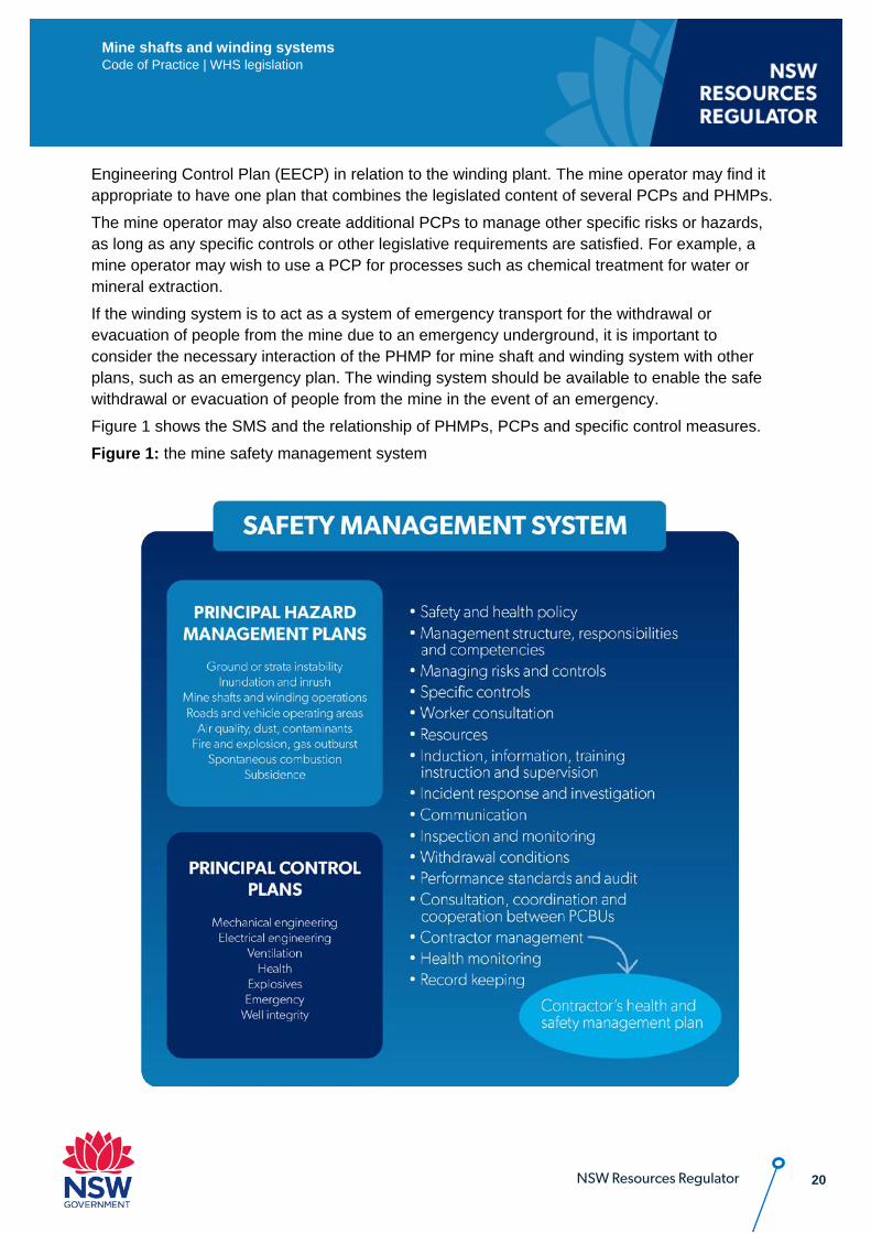
Engineering Control Plan (EECP) in relation to the winding plant. The mine operator may find it appropriate to have one plan that combines the legislated content of several PCPs and PHMPs. The mine operator may also create additional PCPs to manage other specific risks or hazards, as long as any specific controls or other legislative requirements are satisfied. For example, a mine operator may wish to use a PCP for processes such as chemical treatment for water or mineral extraction. If the winding system is to act as a system of emergency transport for the withdrawal or evacuation of people from the mine due to an emergency underground, it is important to consider the necessary interaction of the PHMP for mine shaft and winding system with other plans, such as an emergency plan. The winding system should be available to enable the safe withdrawal or evacuation of people from the mine in the event of an emergency. Figure 1 shows the SMS and the relationship of PHMPs, PCPs and specific control measures. Figure 1: the mine safety management system
21
Mine shafts and winding systems Code of Practice | WHS legislation
NSW Resources Regulator
2. Managing Risk The risk-management requirements from the WHS laws apply at mines.
2.1. General requirements The mine operator must conduct a risk assessment in relation to the PH relating to mine shafts and winding systems.
WHS (MPS) Regulations
9 Management of risks to health and safety (cl 617 model WHS Regs)
(1) A person conducting a business or undertaking at a mine or petroleum site must manage risks to health and safety associated with mining operations or petroleum operations at the mine or petroleum site in accordance with Part 3.1 of the WHS Regulation. Note: See sections 19, 20 and 21 of the WHS Act as applicable (also see section 4 of the WHS (Mines and Petroleum Sites) Act and clause 9 of the WHS Regulations).
(2) A person conducting a business or undertaking at a mine or petroleum site must ensure that a risk assessment is conducted in accordance with this clause by a person who is competent to conduct the particular risk assessment having regard to the nature of the hazard. (details of penalty omitted)
(3) In conducting a risk assessment, the person must have regard to: (a) the nature of the hazard, and (b) the likelihood of the hazard affecting the health or safety of a person, and (c) the severity of the potential health and safety consequences.
(4) Nothing in subclause (3) limits the operation of any other requirement to conduct a risk assessment under this Regulation. Note: A number of specific risk control duties are linked to this clause, see clauses 28–32, 38, 43, 44, 50, 52 and 65–70.
(5) A person conducting a business or undertaking at a mine (who is the mine operator of the mine or who is a contractor) must keep a record of the following: (a) each risk assessment conducted under this clause and the name and competency of the
person who conducted the risk assessment, (b) the control measures implemented to eliminate or minimise any risk that was identified
though any such risk assessment. (6) A person conducting a business or undertaking at a mine or petroleum site is not required to
keep a record of a risk assessment if: (a) the risk assessment is one that an individual worker is required to carry out before
commencing a particular task, and
22
Mine shafts and winding systems Code of Practice | WHS legislation
NSW Resources Regulator
(b) the person keeps a record of risk assessments that addresses the overall activity being undertaken (of which the task forms a part) such as risk assessments carried out in relation to the development of the safety management system for the mine or petroleum site or for a principal hazard management plan.
(7) The record kept under subclause (5): (a) if kept by an operator of a mine or petroleum site—forms part of the safety management
system of the mine or petroleum site and the records of the mine or petroleum site, or (b) if kept by a contractor who has prepared a contractor health and safety management
plan—forms part of the plan.
Part 3.1 of the WHS Regulations sets out general obligations for managing risks to health and safety, while Part 2 Division 1 Subdivision 1 of the WHS (MPS) Regulations (including clause 9) sets out additional general obligations for the management of risk at mines. Both the general obligations and any specific requirements for controlling a particular risk must be complied with such as in:
• Chapter 4 of the WHS Regulations in relation to hazardous work • Chapter 5 of the WHS Regulations in relation to plant and structures • specific requirements in the WHS (MPS) Act and Regulations in relation to mine shafts and
winding systems. The PHMP for mine shafts and winding systems may use the mine’s existing risk management processes, including assessment, so the plan manages risk as required by WHS legislation.
This risk management process involves four steps:
• identify hazards – find out what could cause harm • assess risks – understand the nature of the harm that could be caused by the hazard, how
serious the harm could be and the likelihood of it happening • control risks – implement any mandatory control measures or the most effective control
measure that is reasonably practicable in the circumstances • review control measures to ensure they are working as planned. Each of these steps is discussed in the following sections of this chapter as they relate to developing the PHMP for controlling risks. It is essential that any risk management process be undertaken having regard to the specific circumstances or context in which the risk is being considered. For example, the risks of worker fatigue from operating a winding system must be managed (clause 43 of the WHS (MPS) Regulations). When assessing the risks associated with mine shafts and winding systems, someone with appropriate competence (e.g. electrical, mechanical, geotechnical etc.) should be involved in, or possibly conduct, the risk assessment. The NSW Code of Practice: How to manage work health and safety risks provides guidance on how to comply with requirements under the WHS laws.

23
Mine shafts and winding systems Code of Practice | WHS legislation
NSW Resources Regulator
2.2. Hazard identification All reasonably foreseeable hazards associated with mine shafts and winding systems must be identified. Identifying hazards in the workplace involves finding things and situations that could potentially harm people. Hazards generally arise from the following aspects of work and their interaction:
• physical work environment • plant, structures and energy sources • work tasks and how they are performed • work design and management. • human factors (ergonomic, fatigue etc.). The AS 4024 Safety of machinery series of standards contains useful guidance material for designers and users of plant in ways to identify hazards and provide risk control measures. See also Appendix B – Other Useful Information Common hazards for mine shafts and winding systems include: Gravity (stored potential energy) • Loss of control of the conveyance against the effects of gravity • Fall of materials, equipment, vehicles and components down the shaft that either impact with
the conveyance or people below • Fall of people down the shaft when carrying out shaft activities such as installations,
inspections, tests and maintenance • Drowning of people in the shaft sump Mechanical (kinetic energy) • Loss of control of the conveyance against the effects of kinetic energy • Parts of people in the conveyance protruding outside the conveyance and hitting a fixed
object or the conveyance counterweight Chemical • Asphyxiation of people working in the shaft General plant hazards General plant hazards associated with winding plant such as moving parts, pressurised fluids, electricity and radiation (which are not winding system specific) are covered in the NSW Code of Practice: Mechanical Engineering Control Plan and the NSW Code of Practice: Electrical Engineering Control Plan).
24
Mine shafts and winding systems Code of Practice | WHS legislation
NSW Resources Regulator
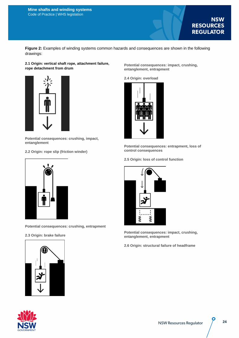
Figure 2: Examples of winding systems common hazards and consequences are shown in the following drawings:
2.1 Origin: vertical shaft rope, attachment failure, rope detachment from drum
Potential consequences: crushing, impact, entanglement
2.2 Origin: rope slip (friction winder)
Potential consequences: crushing, entrapment
2.3 Origin: brake failure
Potential consequences: impact, crushing, entanglement, entrapment
2.4 Origin: overload
Potential consequences: entrapment, loss of control consequences
2.5 Origin: loss of control function
Potential consequences: impact, crushing, entanglement, entrapment
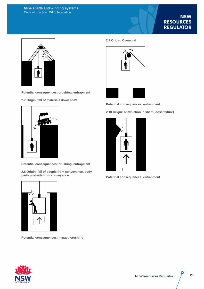
2.6 Origin: structural failure of headframe
25
Mine shafts and winding systems Code of Practice | WHS legislation
NSW Resources Regulator
Potential consequences: crushing, entrapment
2.7 Origin: fall of materials down shaft
Potential consequences: crushing, entrapment
2.8 Origin: fall of people from conveyance, body parts protrude from conveyance
Potential consequences: impact, crushing
2.9 Origin: Overwind
Potential consequences: entrapment
2.10 Origin: obstruction in shaft (loose fixture)
Potential consequences: entrapment
26 NSW Resources Regulator
Mine shafts and winding systems Code of Practice | WHS legislation
There are different methods for undertaking hazard identification and risk assessments. One method is to do a ‘broad-brush’ risk assessment as a first step in identifying the risks which the PHMP should address. A broad-brush risk assessment identifies general hazards so that priorities can be determined for further risk identification and action. This should be followed by an engineering focused hazard identification and risk assessment to identify all the risks associated with the identified hazards of the mine shafts and winding systems. Appendix G provides further information on how these hazards may be analysed using the fault tree method.
2.3. Assessment of risks Clause 9 of the WHS (MPS) Regulations requires that PCBUs at a mine ensure that a risk assessment is conducted by a competent person and is recorded. For mine operators, it must be recorded as part of the mine’s SMS, and for contractors in the contractor health and safety management plan (if applicable). The record must also include the control measures implemented to eliminate or minimise any risk that was identified through the risk assessment. In undertaking a risk assessment, the person must have regard to the:
• nature of the hazard • likelihood of the hazard affecting the health or safety of a person, and • severity of the potential health and safety consequences. Other matters that should be considered in assessing risks are:
• the effect of different operating conditions - normal or abnormal (e.g. shut down and start-up, the shaft environmental condition and possible misuse of equipment due to human error)
• past incidents and potential emergency situations. This consideration particularly affects the availability of the winding system for an emergency situation.
• past, current and planned activities • the reliability and adequacy of existing technology used to control risk i.e. engineering controls • state of knowledge (what the industry knows) about the hazard or risk and how to eliminate or
minimise them. In some cases, further risk assessment of the hazards may be required using an appropriate technique. For example, fault tree analysis, failure modes and effects analysis, human error analysis, bow tie analysis or other techniques. Guidance on these techniques is available in AS/NZS 4204.1201 and 4204.1302, as well as SA/SNZ-HB 89.
27 NSW Resources Regulator
Mine shafts and winding systems Code of Practice | WHS legislation
In addition to the general advice provided in this chapter on managing risk, the mine operator must conduct risk assessments for each PH to satisfy specified requirements:
2.3.1. Investigation and analysis methods Further to the mandatory requirements (see above 1.3 of this code), the mine operator should consider the following areas in a risk assessment:
• keeping the winding system conveyance under control and within predefined parameters • the potential for failure of drive line components including, motors, gearboxes, couplings, drums,
sheaves, supporting structures, ropes, attachments and devices, conveyances. • the potential for failure of the braking system, including the emergency application • the criticality of the winding system remaining operational during an emergency • past incidents • inspections, maintenance and tests on shafts and equipment • people falling down the shaft • protrusions from the conveyance The outcomes of the risk assessments should be incorporated into the life cycle considerations for mine shafts and winding systems and the PHMP.
2.3.2. Assessing the individual and cumulative effects In order to consider the PH individually and cumulatively with other hazards at the mine, the mine operator should: i. follow the mine SMS for risk management requirements to address the interactions between
hazards ii. review risk assessments for other hazards and consider them in the risk assessment for the PH iii. model the combined effects on paper, electronically or in a miniature version of the PH
occurring, and with the variables of different hazards occurring
WHS (MPS) Regulations 23 Identification of principal hazards and conduct of risk assessments (cl 627 model WHS Regs) … (2) The operator must conduct, in relation to each principal hazard identified, a risk assessment that involves a comprehensive and systematic investigation and analysis of all aspects of risk to health and safety associated with the principal hazard. (details of penalty omitted) (3) The operator, in conducting a risk assessment under subclause (2), must: (a) use investigation and analysis methods that are appropriate to the principal hazard being considered, and (b) consider the principal hazard individually and also cumulatively with other hazards at the mine or petroleum site.
28 NSW Resources Regulator
Mine shafts and winding systems Code of Practice | WHS legislation
iv. once treatments are implemented, monitor and review the treatment to ensure the appropriate risk reduction of the hazard has occurred under WHS laws.
2.4. Control of risks Hazard identification and risk assessment is undertaken to lead to the development of appropriate controls to eliminate the risks so far as reasonably practicable or, if that is not reasonably practicable, to minimise risks so far as is reasonably practicable (refer to clauses 33 to 36 of the WHS Regulations for requirements). Appendix F contains a table that summarises typical hazards with references to where guidance on controls can be found in this code.
2.4.1. Specific controls Any specific control measures required in the WHS laws relating to plant or structures must be complied with (so far as it relates to mine shafts and winding systems) and should be included in the PHMP for mine shafts and winding systems. This code identifies many specific control measures required, particularly controls required under the WHS (MPS) Regulations, where they relate to plant and structures. However, these references are not exhaustive. Chapter 5 of the WHS Regulations (clauses 203 to 226) contains a number of specific controls for plant that relate to mine shafts and winding systems including:
• installation and commissioning risks • prevention of unauthorised alteration or interference • the proper use of plant and controls • guarding when used as a control measure • operational controls • emergency stops • warning devices • maintenance and inspection of plant • plant that lifts or suspends loads • pressure equipment • scaffolds • plant with presence sensing safeguarding systems The NSW Code of Practice: Managing risks of plant in the workplace is a good starting point for managing risks associated with plant and for information about requirements for registration of the design of certain types of plant or certain items of plant. The NSW Code of Practice: Safe design of structures provides guidance on design and commissioning of construction work.
2.4.2. Hierarchy of controls There are many ways to control risks and various control options must be considered. This may involve a single control measure or a combination of controls that together provide the required level of protection (layers of protection). Sometimes a single control is not adequate on its own to control
29 NSW Resources Regulator
Mine shafts and winding systems Code of Practice | WHS legislation
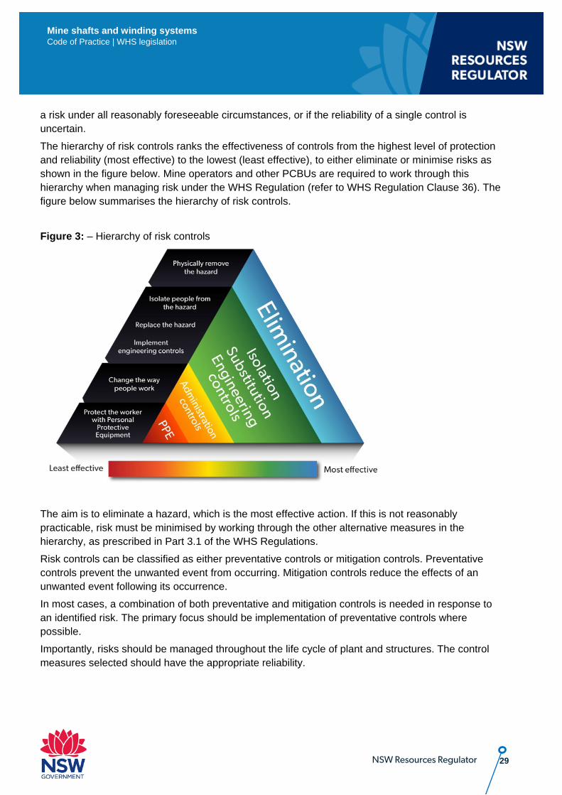
a risk under all reasonably foreseeable circumstances, or if the reliability of a single control is uncertain. The hierarchy of risk controls ranks the effectiveness of controls from the highest level of protection and reliability (most effective) to the lowest (least effective), to either eliminate or minimise risks as shown in the figure below. Mine operators and other PCBUs are required to work through this hierarchy when managing risk under the WHS Regulation (refer to WHS Regulation Clause 36). The figure below summarises the hierarchy of risk controls. Figure 3: – Hierarchy of risk controls
The aim is to eliminate a hazard, which is the most effective action. If this is not reasonably practicable, risk must be minimised by working through the other alternative measures in the hierarchy, as prescribed in Part 3.1 of the WHS Regulations. Risk controls can be classified as either preventative controls or mitigation controls. Preventative controls prevent the unwanted event from occurring. Mitigation controls reduce the effects of an unwanted event following its occurrence. In most cases, a combination of both preventative and mitigation controls is needed in response to an identified risk. The primary focus should be implementation of preventative controls where possible. Importantly, risks should be managed throughout the life cycle of plant and structures. The control measures selected should have the appropriate reliability.
30 NSW Resources Regulator
Mine shafts and winding systems Code of Practice | WHS legislation
2.5. Maintenance of control measures Control measures implemented to control risks presented by identified hazards at a mine must be maintained to ensure their effectiveness under clause 37 of the WHS Regulations.
WHS Regulations
37 Maintenance of control measures
A duty holder who implements a control measure to eliminate or minimise risks to health and safety must ensure that the control measure is, and is maintained so that it remains, effective, including by ensuring that the control measure is and remains: (a) fit for purpose; and (b) suitable for the nature and duration of the work; and (c) installed, set up and used correctly.
The PHMP should identify the methods and systems required to maintain the control measures for mine shafts and winding systems, thereby ensuring they remain effective. The PHMP should identify requirements for monitoring the effectiveness of the controls implemented, including processes for identifying, reviewing and responding to uncontrolled events, such as near miss incidents. This may include maintenance regimes, pre-start and scheduled inspections. Refer to Chapter 6 for further guidance on monitoring and review. Monitoring of control measures may be carried in different ways, such as the development of Trigger Action Response Plans (TARPs). A TARP is an example of a risk management tool that triggers a planned early response to prevent ‘normalisation’, i.e. accepting slow deterioration as 'normal' as there is little variation from day to day. If there is no planned response in place for these particular hazards, a decision to put a risk control in place may be delayed until the hazard cannot be easily controlled. Two examples of where a TARP may be applicable are:
• Monitoring crack initiation and propagation for all ropes and critical structural components through a non-destructive testing program.
• Monitoring brake wear and performance by measuring backpressure on closed loop circuits.
2.6. Review of control measures Clause 10 of the WHS (MPS) Regulations (which refers to clause 38 of the WHS Regulations) requires the mine operator and other PCBUs to review and where necessary revise implemented control measures so as to maintain, so far as is reasonably practicable, a work environment that is without risk to health or safety. These provisions are discussed further in 6.2 of the code below. If the mine operator becomes aware of circumstances where a control measure provided by a designer, manufacturer or supplier does not control the risk it was implemented to control, then the mine operator should notify the designer, manufacturer or supplier of the plant or structure.
31 NSW Resources Regulator
Mine shafts and winding systems Code of Practice | WHS legislation
3. Content of the PHMP – Mine shafts and winding systems
This chapter provides guidance on the matters that need to be addressed by the PHMP for all mines and additional matters to be considered in relation to mine shafts and winding systems. Additional guidance for underground coal mines is provided in Chapter 4 of this Code and should be considered in addition to the information in this chapter.
3.1. General The risk-management process for preparing a PHMP is set out in clause 24 of the WHS (MPS) Regulations:
WHS (MPS) Regulations 24 Preparation of principal hazard management plan (cl 628 model WHS Regs) … (2) A principal hazard management plan must: (a) provide for the management of all aspects of risk control in relation to the principal hazard, and …
The PHMP for mine shafts and winding systems should include, in addition to the matters that must be addressed under clause 24(3), the following:
• a summary of how the controls identified in the risk assessment will be managed to control the principal hazard for each mine shaft and winding system.
• the assessment and validation of the reliability of each identified risk control used to protect persons from the hazards posed by the mine shaft and winding system during each phase of its life cycle (refer to WHS (MPS) Regulations Schedule 2 clauses 2(1)(b) and 3(1)(b) for reliability of safeguards under the MECP and EECP).
• systems for the ongoing management of all risk controls during the operation of the mine shaft and winding system, including the inspection, testing and maintenance of risk controls to the design documentation and functional analysis (refer to Appendix E - Functional Safety and application to winding systems).
(b) so far as is reasonably practicable, be set out and expressed in a way that is readily understandable by persons who use it.
The PHMP must, so far as is reasonable practicable, be set out and expressed in a way that is readily understandable by people who use it. The PHMP may be read and used in part or in full by persons, so each part of it should be complete and appropriate for the potential needs. The use of headings, diagrams and common words may assist understanding.
32 NSW Resources Regulator
Mine shafts and winding systems Code of Practice | WHS legislation
(3) A principal hazard management plan must: (a) describe the nature of the principal hazard to which the plan relates, and
The description of the PH relating to mine shafts and winding systems should include:
• how the PH may occur at the mine • the purpose of the winding system and intended use and life • general arrangement drawings of the shaft and winding system • designed winding loads and speeds for both people and materials • a functional specification on the controls of the winding system, including design limits and set
points • identification of each apparatus or component which constitutes the winding system • operational requirements • inspection, test and maintenance requirements of the shaft and winding system • communication and emergency requirements. Where a mine has multiple shafts and winding systems, the description of the PH may be different depending on the purpose of the winding system. For example, a mine may have:
• a bulk haulage shaft winding system that only lift people to carry out inspections, tests and maintenance on the winding system itself, the shaft, or the shaft sump
• a shaft winding system used to lift people to and from or between levels in an underground mine • a shaft sinking winding system • a conveyor belt drift winding system for carrying out conveyor inspections and a second means
of egress from the mine.
(b) describe how the principal hazard relates to other hazards associated with mining operations or petroleum operations at the mine or petroleum site, and
The PHMP must describe how the PH impacts on other hazards at the mine. The nature of their relationship should be used as an ongoing consideration in managing their interactions. In particular, the PH relating to mine shafts and winding systems should be described in relation to other hazards and hazard events at the mine, including:
• inrush hazards for people working in the shaft sump • hazards associated with energy sources and services located within the shaft, such electrical
power supply, compressed air lines, pumping lines, methane drainage lines, communication and monitoring lines
• ground or strata instability • a fire, explosion or windblast in the mine The PHMP should also consider how the PH is managed by the mine emergency management plan, including:
• how should the mine shaft and winding system be used in a mine emergency • how people can be withdrawn or evacuated from or around the mine shaft (including, sumps and
winding system conveyances).
33 NSW Resources Regulator
Mine shafts and winding systems Code of Practice | WHS legislation
• what availability criteria for the winding system is necessary to ensure the winding system is available for operation in the event of a mine emergency.
(c) describe the analysis methods used in identifying the principal hazard to which the plan relates, and
The description of the analysis methods should address the following:
• the hazard identification technique(s) used • the risk assessment technique(s) used, such as WRAC, FEA, FMECA, fault tree analysis, bow
tie analysis, human error analysis (refer HB SA/SNZ-HB 89) • the assessment and validation of the reliability of the control measures used • the data and information used e.g. codes, technical publications (standards, guidelines), safety
alerts, incident data and the specific mine data • the people who will be involved e.g. workers, designers, maintainers, specialists, operators • the assessment and control of both the individual and cumulative effects of hazards (refer 2.3 of
this code).
(d) include a record of the most recent risk assessment conducted in relation to the principal hazard, and
The PHMP must include a record of the most recent risk assessment for mine shafts and winding systems. There should be several risk assessments for each mine shaft and winding system, including:
• preliminary hazard analysis and identification of safety critical functions • design risk assessment(s) on required control measures for intended use • design risks assessment(s) on detailed analysis of proposed controls • installation and commissioning risk assessment • operations risk assessment which includes operation, inspection and testing, maintenance,
control, communication, operator and maintenance people competencies, training requirements and emergency procedures.
These risk assessments should form the basis of the operational and maintenance documentation for the mine shaft and winding system and should be included in the safety file, refer 5.7.
(e) describe the investigation and analysis methods used in determining the control measures to be implemented, and
The description of the investigation and analysis methods should address the following:
• the matters listed above in relation to clause 24(3)(c) of the WHS (MPS) Regulations • the intended outcomes of the analysis and clarification of technical terms used • the suitability of the methods used and the reasons for selecting such methods • the magnitude of the energy/hazard being controlled • the potential level of risk or residual risk, should the control measure not be in place or fail • the required reliability of the control measure, refer MECP Code and EECP Code • the assessment and validation of the reliability of the control measure used.
34 NSW Resources Regulator
Mine shafts and winding systems Code of Practice | WHS legislation
(f) describe all control measures to be implemented to manage risks to health and safety associated with the principal hazard, and
The PHMP must describe all control measures so it is clear what is to be implemented. Specific details and implementation may be referenced to separate documents, such as procedures. The description of control measures should address any life cycle inspection, tests and maintenance, including:
• Any proof testing, or partial proof testing requirements to meet functional safety performance requirements. Refer to Appendix E of this code and MECP Code and EECP code.
• Non-destructive and destructive testing requirements for ropes, structures and other load path elements such as couplings. Refer to Appendices A and B of this code.
• Discard criteria. Refer to 4.3 and Appendix C of this code.
(g) describe the arrangements in place for providing the information, training and instruction required by clause 39 of the WHS Regulations in relation to the principal hazard; and
Clause 39 of the WHS Regulation sets out requirements for the ‘Provision of information, training and instruction’ and requires a PCBU to ensure it is suitable and adequate, depending on the nature and risks of the work, and control measures to be implemented. The PHMP should address how the mine operator will communicate and deliver the information, training and instruction to all workers exposed to the PH associated with mine shafts and winding systems. This may include contractors, consultants, specialists, designers, operators and maintenance people. For example, maintaining a training schedule and register. In particular, suitable specialist information, training and instruction should be given to workers in shafts and sumps, and technical work, such as rope capping.
(h) refer to any design principles, engineering standards and technical standards relied on for control measures for the principal hazard, and
The PHMP must refer to any design principles, engineering standards and technical standards relied on for the control measures. This should include:
• the engineering and technical standards listed in Appendix A of this code • any relevant standards listed in Appendix B of this code • the designer’s assumptions and performance requirements when applying the design principles
and engineering and technical standards • the independent verification of the design principles and standards used. These may be identified in the risk assessment. They should be listed and how/where they can be accessed.
(i) set out the reasons for adopting or rejecting each control measure considered.
The reasons for adopting or rejecting each control measures should take into account industry standards and practices, i.e. what are other mine operators doing to control the same risk. The reasons may be stated in a summary in the PHMP and the risk assessment records referenced.
35 NSW Resources Regulator
Mine shafts and winding systems Code of Practice | WHS legislation
(4) The operator of a mine or petroleum site must consider the following when preparing a principal hazard management plan for a principal hazard at the mine or petroleum site: (a) the matters set out in Schedule 1 in respect of the principal hazard, and (b) any other matter relevant to managing the risks associated with the principal hazard at the mine or petroleum site.
Refer to section 3.2 in this code below for guidance on how to satisfy the requirements in Schedule 1.
(5) The operator of a mine or petroleum site at which there is a principal hazard must ensure that no mining operations or petroleum operations are carried out at the mine or petroleum site that may give rise to the hazard before the principal hazard management plan for the hazard has been prepared in accordance with this clause. (details of penalty omitted)
The PHMP should be reviewed and changed as circumstances at the mine changes, so that the control measures for the PH remain effective. Refer to Chapter 6 of this code for guidance on reviewing the PHMP. For example, the initial PHMP for a shaft sinking operation will be different to the PHMP for the installation and commissioning of a new winding system designed to convey people or materials. The PHMP should be altered to address the life cycle effects of the shaft and winding system.
3.2. PHMP: additional matters to be considered In addition to the requirements outlined in section 3.1 of this code, the mine operator must consider the matters set out in Schedule 1 clause 3 of the WHS (MPS) Regulations when preparing a PHMP and developing the control measures to manage the risks associated with mine shafts and winding systems.
WHS (MPS) Regulations Schedule 1 Principal hazard management plans – additional matters to be considered (Clause 24) (Sch 19 model WHS Regs) 3 Mine shafts and winding systems The following matters must be considered in developing the control measures to manage the risks associated with mine shafts and winding systems: a) the potential for instability and loss of integrity of the shaft,
Consideration should be given to: i. the geological strata conditions that the shaft extends through (such as rock, clays, water,
shale, slabbing, strata pressures) and those recommendations of a competent geotechnical engineer
ii. using fit-for-purpose shaft lining methods (where appropriate) to consider the life cycle considerations and management of the strata conditions that the shaft extends through
36 NSW Resources Regulator
Mine shafts and winding systems Code of Practice | WHS legislation
iii. the need for drainage of water behind any shaft linings, e.g. use of shaft water rings iv. the use of shaft guides or guide ropes to prevent a conveyance from contacting a shaft wall v. the need to carry out strata inspections and maintenance work on the shaft walls vi. a safe means for the regular inspection and monitoring of shaft geological conditions and
supporting structures and services attached to the shaft walls vii. the means to prevent any shaft instability from causing uncontrolled contact with conveyances,
such as fitting shaft obstruction detection limit switches to the conveyance or guides.
(b) the potential for fires in underground operations, the shaft or winder areas,
Consideration should be given to potential fires in the following areas: (i) underground operations:
• the toxic effects of product combustion affecting people being conveyed in the shaft • the emergency evacuation of people from the mine • any issues associated with ventilation fan stoppages (if required) for emergency winding system • the potential for a fire in another area of the mine to affect the winding system. (ii) shaft:
• any items in the shaft that may be fuel or ignition sources for fires, such as rags, excessive lubricants, areas where frictional heating may occur
• the combustible properties of the selection and installation of materials used within the mine shaft and winding system
• the potential for a shaft fire to contaminate the mine atmosphere as an intake shaft • the means to detect and suppress a fire in the shaft or sump. (iii) winding system areas (winder house):
• the identification of all potential fuel, ignition sources and scenarios (e.g. brakes which may drag) and control measures to prevent a fire from initiating and propagating
• the means for early detection of a fire (e.g. installing smoke and fire detectors connected to the winder monitoring and control system)
• the means to suppress a fire (e.g. automatic fire suppression systems in the winder house and winder control components)
• the potential for plant malfunction to initiate a fire • the potential for a fire to cause an unsafe plant malfunction.
(c) the potential for any unintended or uncontrolled movement of the conveyances within the shaft,
Consideration should be given to:
(i) the failure of the winding system’s control system (MDG 33.6 – Guidelines for the design, commissioning and maintenance of drum winders – control systems provides guidance for control systems)
(ii) the failure of the winding system rope(s) (iii) the failure of supporting structures or mechanical load components
37 NSW Resources Regulator
Mine shafts and winding systems Code of Practice | WHS legislation
(iv) the failure of the conveyance itself (v) an overload of the winding system (vi) the failure of the braking system (vii) rope slip on a friction winding system caused by excessive acceleration or deceleration (viii) any control function designed to move the conveyance with the conveyance doors not
properly closed (ix) the use of balance ropes, guides or other devices to prevent undue horizontal movement of
the conveyance while stationary, ascending or descending (x) unbalanced load conditions (xi) shaft obstruction.
(d) the potential for a conveyance to fall down the shaft,
Consideration should be given to:
(i) the matters listed above in relation to Schedule 1 clause 3(c) of the WHS (MPS) Regulations (ii) a tail rope failing and falling on the conveyance (iii) the provision of fit for purpose rope inspections (iv) any material or equipment on the surface or intermediate landing falling down the shaft to the
conveyance (v) strata failure or structural failure of services within the shaft and falling down on to the
conveyance (vi) using the conveyance braking systems for drift slope haulages (vii) using the conveyance braking systems for vertical shafts where fixed guides or a rack and
pinion is used (viii) using the bumpers or arrestors to assist in the safe arrestment of an ascending or
descending conveyance (ix) using detaching devices and overwind safety catches (x) the conveyance falling when brakes are lifted without sufficient drive torque to control the
conveyance (xi) life cycle management of safety critical systems and components so they remain fit for
purpose. For example, ropes and conveyance attaching devices are critical.
(e) the potential for failure of, or damage to, equipment and control measures, including the following: (i) control measures that are intended to prevent any shaft conveyance from overwind, excessive acceleration or deceleration, unsafe or excessive speeds or uncontrolled movement,
Consideration should be given to the MDG 33 Winding system series of guidelines and the technical standards listed in Appendix A.
In addition to the MDG 33 series of guidance, consideration should be given to:
• the use of a fit for purpose control system with sufficient integrity to keep the conveyance under control
• accelerations and decelerations being less than those required to prevent harm to people
(ii) control measures that are intended to detect the presence of slack rope, drum slip conditions or unsafe tail rope conditions,

38 NSW Resources Regulator
Mine shafts and winding systems Code of Practice | WHS legislation
Slack rope may be caused by:
• a jammed conveyance while the drum continues to wind, e.g. keps/chairs not disengaging, conveyance jamming in guides etc.
• an overwind of the conveyance into the sump or flat area at the bottom of a drift • conveyance brakes being applied while the drum winds • excessive friction between the conveyance and guides • rope or rope attachment failures, including guide, rubbing and balance ropes. A drum slip (rope slipping on the drive sheave) condition (friction winder only) may be caused by:
• an overload of the conveyance • out of balance between conveyance and counterweight • too high brake torque application to drive pulley • too high acceleration or deceleration of the drive pulley • uneven tensioning between ropes for multiple rope winding systems • uneven sheave grooving between rope grooves for multiple rope winding system.
An unsafe tail rope conditions (friction winder only) may be caused by:
• undetected deterioration of the rope itself • a caught conveyance or counterweight or excessive friction between counterweight or
conveyance and guides • excessive deceleration or acceleration • out of balance between the conveyance and counterweight The winding system should have control measures that automatically prevent the above conditions occurring. MDG 33.6 Guidelines for the design, commissioning and maintenance of drum winders – control systems provides guidance on control measures that are intended to detect slack rope, drum slip conditions or unsafe tail rope conditions.
(iii) braking systems and systems performing an equivalent function that are intended to ensure that the winder remains under control,
Consideration should be given to:
(i) the control measures for ropes recommended in Chapter 4 of this code (ii) the potential failure of the braking (or equivalent) system used for normal retardation of the
winding system, which provides for a conveyance to operate within a defined speed distance envelope
(iii) the maximum dynamic torque which the braking system may be subjected to during the full winding cycle and loading conditions.
(iv) the automatic application of brakes when the defined speed distance envelope is or is likely to be compromised
(v) the automatic application of brakes when the drive power fails or there is low stored energy (i.e. fluid pressure) that may fail to control the brakes
(vi) an emergency manual application of the braking system
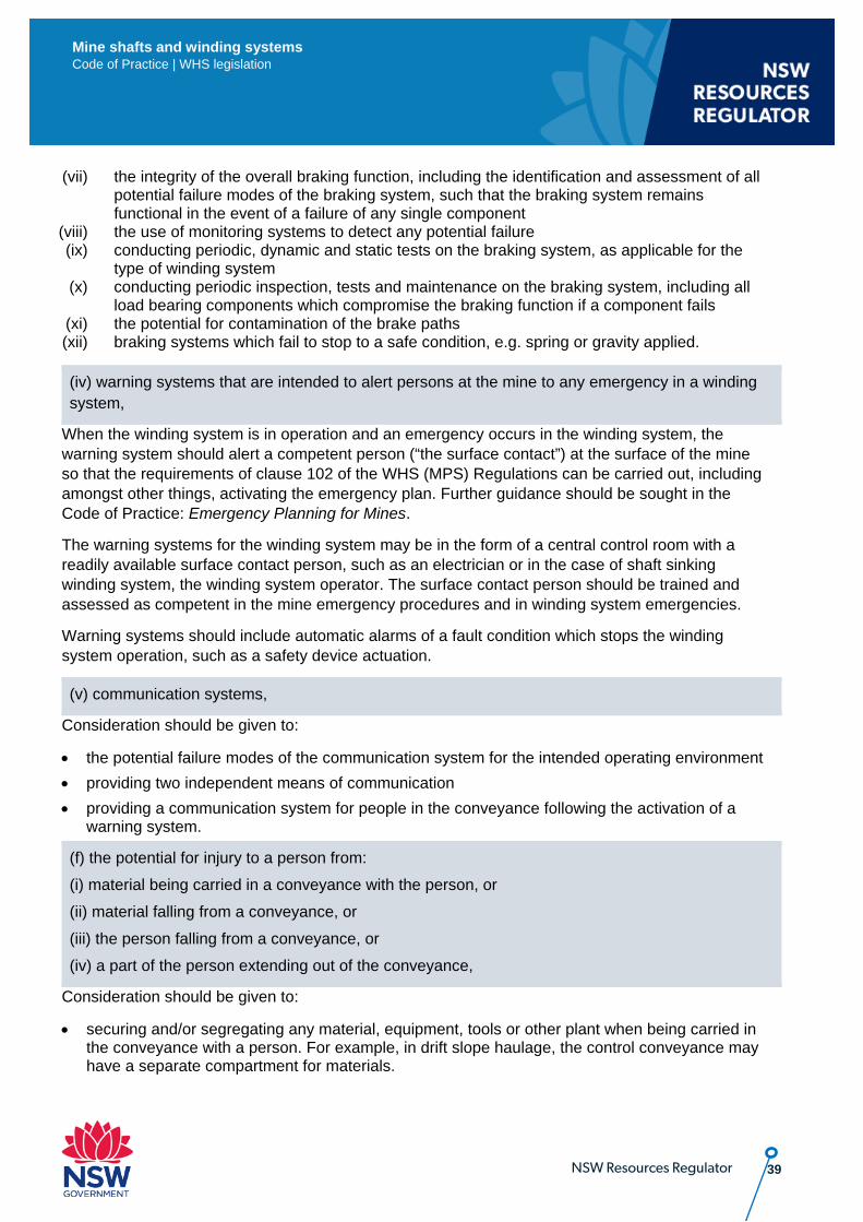
39 NSW Resources Regulator
Mine shafts and winding systems Code of Practice | WHS legislation
(vii) the integrity of the overall braking function, including the identification and assessment of all potential failure modes of the braking system, such that the braking system remains functional in the event of a failure of any single component
(viii) the use of monitoring systems to detect any potential failure (ix) conducting periodic, dynamic and static tests on the braking system, as applicable for the
type of winding system (x) conducting periodic inspection, tests and maintenance on the braking system, including all
load bearing components which compromise the braking function if a component fails (xi) the potential for contamination of the brake paths (xii) braking systems which fail to stop to a safe condition, e.g. spring or gravity applied.
(iv) warning systems that are intended to alert persons at the mine to any emergency in a winding system,
When the winding system is in operation and an emergency occurs in the winding system, the warning system should alert a competent person (“the surface contact”) at the surface of the mine so that the requirements of clause 102 of the WHS (MPS) Regulations can be carried out, including amongst other things, activating the emergency plan. Further guidance should be sought in the Code of Practice: Emergency Planning for Mines.
The warning systems for the winding system may be in the form of a central control room with a readily available surface contact person, such as an electrician or in the case of shaft sinking winding system, the winding system operator. The surface contact person should be trained and assessed as competent in the mine emergency procedures and in winding system emergencies.
Warning systems should include automatic alarms of a fault condition which stops the winding system operation, such as a safety device actuation.
(v) communication systems,
Consideration should be given to:
• the potential failure modes of the communication system for the intended operating environment • providing two independent means of communication • providing a communication system for people in the conveyance following the activation of a
warning system.
(f) the potential for injury to a person from: (i) material being carried in a conveyance with the person, or (ii) material falling from a conveyance, or (iii) the person falling from a conveyance, or (iv) a part of the person extending out of the conveyance,
Consideration should be given to:
• securing and/or segregating any material, equipment, tools or other plant when being carried in the conveyance with a person. For example, in drift slope haulage, the control conveyance may have a separate compartment for materials.
40 NSW Resources Regulator
Mine shafts and winding systems Code of Practice | WHS legislation
• minimising the number of people in the conveyance when loads are attached to it, such as when a material or supply skip is attached to a dolly car.
• using fixed barriers to prevent a person falling from a conveyance and extending parts of the person outside the conveyance
• using door locks to prevent a conveyance door from being opened, unless the conveyance is docked
• using door interlocks to bring a winding system to stop if the door is opened when the conveyance is not docked
• using guards (including conveyance doors) to prevent people from contacting fixed objects when being conveyed in the shaft. Guidance guards and reach dimensions are provided in the AS 4024.1 Safety of machinery series of standards.
• following the NSW Code of Practice: Managing the risk of falls at workplaces when people are carrying out shaft work inside the shaft from outside the conveyance.
(g) provision for the emergency exit of persons from a conveyance.
In making provision for emergency egress of persons from any conveyance, consideration should be given to:
(i) designing the conveyance to allow people to safely move from inside the conveyance to its roof (where applicable)
(ii) the depth of the wind (iii) the means of recovering people trapped in the conveyance part way in the wind cycle in the
shaft mid-way (iv) the size and number of persons the conveyance holds (v) using alternative means to recover people from the conveyance if the winding system
overwinds into the headframe or the sump. For example, a separate hoist used for maintenance in winding systems operations, ladder way etc.
(vi) time for any external emergency service to arrive on site (vii) using alternative drive systems such as, hydraulic drives, pony drives
41 NSW Resources Regulator
Mine shafts and winding systems Code of Practice | WHS legislation
4. Mandatory risk control measures – mine winding systems
4.1. Specific risk controls – WHS There are a number of specific controls required under the WHS (MPS) Regulations for all underground mines that apply to winding systems at mines. A specific risk control is a mandatory requirement that must be complied with if that type of plant exists at the mine. The PHMP should detail the arrangements that are required for the mine to achieve compliance with the specific control measures for mine shafts and winding systems.
4.1.1. Winding systems
WHS (MPS) Regulations 47 Winding systems (cl 644 model WHS Regs) (1) The mine operator of an underground mine (other than an opal mine) must ensure that every winding system used or that may be put into use at the mine includes the following: a) ropes and devices that can withstand all forces reasonably expected to be borne by the ropes and devices,
Forces reasonably expected to be borne by the ropes and devices may include, without limitation:
(i) dead loads, including ropes, attachments and conveyances (loaded and unloaded) (ii) live loads, including
• dynamic and inertial effects • loads applied by the drum • tangential forces due to fleet angles • forces resulting from normal acceleration and deceleration of the winding system • forces resulting from the application of the brakes
(iii) abnormal live loads potentially imposed by the drive, including stall conditions.
The devices should be considered with all components included in the load chain from the winding system drive pulley to the conveyance itself. This includes the drive pulley and its foundations, the braking systems including its posts, rope anchorage to the drive pulley, any bend pulleys or sheaves, the headframe structure including its foundations (and other supporting structures), rope attachments, detaching hooks, rope capping’s, drawbars and connecting links, rope swivels and swivel hooks, shackles and chains, overwind safety catch systems, arresting systems, gripper systems and conveyances. These devices should be designed to comply with the relevant standards listed in Appendix A.
42 NSW Resources Regulator
Mine shafts and winding systems Code of Practice | WHS legislation
4.1.1.1. Factor of safety (FOS)
Rope and devices should be designed with FOS that takes into account all forces reasonably expected to be borne by the ropes and devices.
Unless otherwise stated in the standards listed in Appendix A, the following FOS (when assessed to dead loads) should apply:
• for ropes – refer to Appendix C – Rope FOS • for mechanical single line components that:
o do not include threads (screwed connections) in the load path, FOS of 10:1 o include threads in the load path, FOS of 15:1
Other components that may affect the integrity of the winding system should be designed to a minimum of 120% of the minimum rope break design load. This should include drum foundations, drums, sheaves, shafts, conveyances and structures. Note: any additional loads should be considered in their design.
(b) control measures to prevent, so far as is reasonably practicable, any shaft conveyance from overwind, moving at an unsafe speed, excessive acceleration and deceleration and uncontrolled movement,
4.1.1.2. Overwind An overwind situation is when the conveyance has over wound or gone past the normal limit of travel. Drum winding system
In case of a conveyance being overwound on a drum winding system, an overwound conveyance arrester should be installed in the headframe and below the lowest landing in the shaft to limit the potential injury from an overwind. The conveyance should have a device capable of enabling it to be detached when overwound. Some winders may achieve this without the devices. For example, shaft sinking winders which operate at sufficiently slow speeds and are designed such that the drive torque will not cause failure of the rope, headframe or sheaves. The arresting system should have devices that prevent the conveyance from falling down the shaft, automatically applies the brakes and removes the power before it reaches any permanent obstruction.
4.1.1.3. Friction winding system In case of a conveyance being overwound on a friction winding system, an overwound conveyance arresting system should be installed in the headframe and below the lowest landing in the shaft to limit the potential injury from an overwind. The arresting system should have devices that prevent the conveyance from falling down the shaft, automatically applies the brakes and removes the power before it reaches any permanent obstruction.
43 NSW Resources Regulator
Mine shafts and winding systems Code of Practice | WHS legislation
4.1.1.4. Unsafe speed Unsafe speed is any speed which is not within the design specifications of the winding system. All winding systems have a speed distance envelope which includes an acceleration or deceleration profile, which is purpose designed to allow safe and reliable travel. Any speed outside the profile is likely to lead to consequences such as damaged plant, injuries and deaths. Devices should be provided to automatically limit the speed of conveyances to a safe level so that the conveyance can land safely after travelling through safe acceleration and deceleration. In the case of a manually controlled winding system or slope haulage, a rope speed indicator should be visibly located on the winding system so that it can be read by the winding system operator, and the control measures should take into account possible human error.
4.1.1.5. Uncontrolled movement Uncontrolled movement is any movement of the winding system which is unexpected that is not within the design specifications of the winding system. If the design, manufacture, installation, commissioning and maintenance of the winding systems have been risk managed, then uncontrolled movements should be extremely rare. Mechanical and/or winding system control failures may lead to such an event. These events can result in damaged plant, injuries and deaths.
Controls for the risk of uncontrolled movement include:
a) detection to prevent conveyance from moving in an undesired direction b) using guides in the shafts for conveyances c) using interlocks to prevent the conveyance from moving when the conveyance doors are not
closed correctly d) using suspension equipment capable of withstanding stall conditions.
In the case of the shaft becoming obstructed, the winding system should have controls that prevent and/or mitigate contact with the obstruction, such as:
• using slack and tight rope monitoring
• using stall protection
• removing power to a particular part of the winding system before it makes any contact
• applying brakes automatically to bring the winding system to a stop. Consideration should be given to automatic synchronisation of the conveyance’s position indicator and automatic safety devices with the conveyance’s position at defined points.
(c) at least 2 braking (or equivalent) systems that ensure the winder remains under control in the event of a failure in any one of the systems,
All braking systems should be fail safe. When applied, the braking systems should not cause a dangerous condition. Guidance on braking systems and their performance parameters is provided in the relevant parts of the MDG 33 Winding System series of guidelines.
44 NSW Resources Regulator
Mine shafts and winding systems Code of Practice | WHS legislation
4.1.1.6. 2 braking systems Where two braking systems are used, they should be independent from each other. Each independent braking system should be capable of holding the winder drum stationary while supporting at least 200% of the maximum static out of balance torque when applied to the drive drum (or drive sheave). When applied, the braking systems should not create unsafe deceleration. Risk management techniques, such as engineering analysis, should be applied where old winding systems are being used but are unable to reach the required 200% of the maximum static out of balance torque. Appropriate levels of engineering knowledge and expertise need to be utilised in such assessments. If older winding systems are relocated or upgraded, then they should achieve at least 200% of the maximum static out of balance torque.
4.1.1.7. Brake systems performing an equivalent function Multi-channel type braking systems may be used as a system performing an equivalent function if there is sufficient engineering rigour to demonstrate its equivalence. Multi-channel type braking systems should include:
• at least two separate brake paths • a documented and detailed analysis on the failure modes of the braking system • a documented functional safety assessment to the relevant parts of a recognised standard,
including independent verification that the braking system meets the designed performance requirements
• a total static brake torque of at least 175% applied to each brake path.
If any component of the braking system fails, the braking system should be capable of holding the winder drum stationery while supporting at least 200% of the maximum static out of balance torque when applied to the drive drum (or drive sheave). The failure of any component should be detected where reasonably practicable.
(d) control measures that detect any of the following malfunctions that may be present: (i) slack rope (ii) rope slip, (iii) unsafe balance rope conditions, (iv) unsafe coiling of rope,
Winding systems are designed to function correctly with the rope being taut. The degree of tension within the rope will be determined in the design parameters. The following malfunctions may result in plant damage, injury and/or death.
45 NSW Resources Regulator
Mine shafts and winding systems Code of Practice | WHS legislation
4.1.1.8. Slack rope if the rope is not taut Rope slip occurs in friction winding systems when the rope(s) slips on the drive drum. This could be caused for example by a shaft obstruction when the conveyance is travelling up or down causing tight or slack rope respectively. The design of the drive mechanism is dependent on the rope maintaining the design coefficient of friction with the drive drum to function correctly. A control device should indicate slip of the rope relative to the driving sheave and stop the winding system if a predetermined design rate of slip is exceeded.
Unsafe balance rope conditions occur when the balance rope is operating outside its design limitations. For example, the balance rope may be detached or bird-caged.
Devices that may be used to detect the above malfunctions include:
• tail rope switch • positioning limit switched • designing the rope to minimise malfunctions.
(e) control measures that cause the winder to be brought to a safe state when a condition or malfunction referred to in paragraph (d) is detected,
A safe state refers to when the winding system is operating within its design limitations. Devices (such as the braking systems) will be incorporated into the control measures for the winding system.
MDG 33.6 Guidelines for the design, commissioning and maintenance of drum winders – Control systems provides guidance on these devices.
(f) warning systems to alert persons at the mine to any emergency in a winding system,
An emergency in a winding system may occur if any component or device malfunctions. Emergencies may include:
• people trapped in the conveyance part way in the wind cycle (i.e. mid shaft) due to: o power loss o malfunction of the winding system o safety device activating and bringing the winding system to a safe state
• the winding system overwinds into the headframe • the winding system overwinds into the sump (vertical shaft) or bottom of the wind.
If any of these emergencies occur, the warning system should automatically alert a person (“the surface contact”) at the surface of the mine so that the requirements of clause 102 of the WHS (MPS) Regulations can be carried out, including amongst other things, activating the emergency plan. Further guidance is provided in the NSW Code of Practice: Emergency Planning in Mines.
4.1.1.9. Emergency communications between the conveyance and control room Where there is limited egress from the underground, the safety of all people working in the underground mine may be at risk. The WHS (MPS) Regulations sets out a number of specific control measures that must be implemented (see Chapter 4 of this Code for guidance on these requirements). The warning systems must alert a surface contact (such as the winding system operator and/or competent person(s) at remote locations) to any malfunctions in the winding system. The alarms should have a visual and audible function.
46 NSW Resources Regulator
Mine shafts and winding systems Code of Practice | WHS legislation
The warning systems may alert surface contacts to other risks associated with the mine shaft and winding system depending on the risk management arrangements at the mine (see 3.2 above for more details).
(g) if it is reasonably practicable, remote monitoring of the functions of the system,
Remote monitoring enables people to monitor the winding system functions from a remote location (such as, winder room, conveyance, mine control room) to avoid exposure to risks.
After conducting a risk assessment, the mine operator should decide the following:
• the location of the remote monitoring site (such as, at the mine or off site, or a combination of both)
• the purpose of the remote monitoring (such as, operation, maintenance, emergency management)
• how the remote monitoring relates to other arrangements (such as, withdrawal of people, ventilation, the emergency plan).
Remote monitoring should monitor:
(i) the position of each conveyance in the shaft. For example, the position of rope hauled train of vehicles in the roadway.
(ii) any alarms of fault conditions (iii) the winding system mode of operation, for example, manual, automatic, maintenance (iv) the operational conditions of the mine shaft and winding system required in certain
circumstances, such as mine emergencies.
(h) an effective means of communication: (i) between the surface and any shaft conveyance used for carrying persons; and (ii) between the point of control of the winder and the entry to every shaft that is in use
The design of an effective means of communication should incorporate the risk management process. There should be at least two independent means of communication to the conveyance. Forms of communication may include single or dual radio systems, lock bell systems (signal confirmation system), dedicated control systems, special key system or telephones.
Appendix D provides a sample manual signals code for winding operations. Workers must be trained in the relevant version of the code used at the mine. The code should be prominently displayed at appropriate locations and readily accessible to all workers who are required to use it.
Communication between the winding system and emergency communication systems may be conducted electronically or manually via people transferring information between the two. Procedures for when emergency alarms are activated should have persons communicating through the winding communication system.
(i) a device that safely attaches ropes to conveyances,
Devices for attaching ropes to conveyances may include capels and rope sockets. The devices should comply with the relevant standards listed in Appendix A.
47 NSW Resources Regulator
Mine shafts and winding systems Code of Practice | WHS legislation
(j) in the case of multi-rope winders, devices that load the ropes as uniformly as possible. (details of penalty omitted)
Uniform load distribution should be carried out using devices which comply with the standards listed in Appendix A. Uniform loading may be accomplished either through automatic balancing, maintenance procedures or a combination of both. Examples include verniers, hydraulic load compensators, inserts or equalisation beams.
(2) The mine operator must ensure that the condition and performance of the winding system, and its components, are tested and monitored at intervals to ensure the safe performance of the system. (details of penalty omitted)
The mine operator and other associated PCBUs must ensure that requirements of the WHS Act are adhered to with respect to making information available to those associated with life cycle aspects of the winding system. Such information will include testing and monitoring of the winding system to ensure safe condition and performance.
The MECP and the EECP codes provide general guidance on maintenance of plant and structures. In developing the maintenance system for winding systems, consider the relevant technical standards listed in Appendix A, as well as the following:
• maintenance of ropes • rope attachments, detaching hocks, rope cappings, couplings, drawbars and connecting links,
rope swivels and swivel hocks, shackles, safety chains, detaching hooks, arresting gear, overwind safety catch systems (not frozen), grippers
• winding system controls such as programmable logic controllers, electro-mechanical controllers etc.
• conveyance(s) • drive train • winding system drum brakes –static and dynamic testing, fluid power systems • conveyance brakes • shafts water rings, rope & fixed guides, sumps • rescue equipment and fall protection gear • emergency power supply • maintenance platforms • sheaves • winding system drums • gantries and walkways • safety gear in the conveyance, harness, lanyards • rope tensions • car and landing door equipment and catchments • fit for purpose chairing beams
48 NSW Resources Regulator
Mine shafts and winding systems Code of Practice | WHS legislation
• pit clearances, shaft obstructions i.e. look for change • trailing cables • guide roller assemblies • periodic Non-Destructive Testing (NDT) by competent person to areas identified by the designer • inspection of structures, foundations, winder house, headframe, landings, stages, sump • safety devices generally.
(3) The mine operator must ensure that energy lockout devices are fitted to all mechanical and electrical plant associated with any shaft at the mine, including any mechanical and electrical plant associated with the operation, maintenance or use of the shaft. (details of penalty omitted)
Lockout devices isolate and/or control the energy associated with the winding system. Lockout devices are used when maintenance and repairs, including inspection, testing and examinations are undertaken on the winding system or parts thereof.
Further guidance on energy isolation is provided in the NSW Code of Practice: Mechanical Engineering Control Plan and the NSW Code of Practice: Electrical Engineering Control Plan, MDG 40 Guideline for hazardous energy control (isolation or treatment) and AS 4024.1 Safety of machinery series of standards.
Energy associated with winding systems may be stored in—
• parts liable to move by gravity • electrical power supply • stored energy in capacitors and accumulators • pressurised fluids • springs.
Examples of lockout devices include load-break electrical isolators, manually operated ball or gate valves, or chairing beams.
Safe work procedures for energy isolation and dissipation should include:
(a) isolating (for example, disconnecting or separating) the plant or defined parts of the plant from all power supplies
(b) locking or securing all the isolation units in the isolating position, as necessary (for example, in large machines or in installations)
(c) dissipating or restraining any stored energy which may give rise to a hazard (d) verifying by means of a safe working procedure that effective isolation and/or energy
dissipation has been achieved.
49 NSW Resources Regulator
Mine shafts and winding systems Code of Practice | WHS legislation
4.1.2. Ropes
WHS (MPS) Regulation 48 Ropes The mine operator of an underground mine (other than an opal mine) must ensure that: (a) each rope used for the purposes of a winding system or slope haulage is regularly inspected and tested to ensure that it is safe for that use, and (b) criteria are established to determine when a rope is no longer suitable for any such use. (details of penalty omitted)
General guidance on ropes is provided in MDG 33.7 Guidelines for the design, commissioning and maintenance of drum winders – Examination, testing and retirement of ropes and AS 4812 Non-destructive examination and discard criteria for wire ropes in mine winding systems.
The mine operator should provide for the regular monitoring and testing of ropes used for winding systems or slope haulage, including:
• testing by a National Association of Testing Authorities, Australia, accredited laboratory • the destructive testing of a sample of all newly manufactured ropes, which is then used as a
reference for rope discard criteria • the periodic destructive testing of the conveyance end of drum winder ropes • the periodic non-destructive testing of all ropes • the regular inspection and measurements of ropes A discard criterion should be established by the mine operator so that unsafe rope does not remain in use. Guidance on discard criteria is provided in MDG 33.7 and AS 4812.
A competent person for determining rope suitable for winding should be determined by the mine operator in consultation with appropriate persons, for example the designer.
Only newly manufactured ropes should be installed on mine winding systems. An exception to this may apply to shaft sinking winding systems, where a used rope may be reinstalled on the winder drum, if the following requirements are in place and carried out since the rope was last used:
• the original destructive test results on the new rope (now, a used rope) are available • the history of the rope is known and documented • a destructive test carried out on the end of the rope • the full length of the rope undergoes a visual inspection with measurements and has undergone
a non-destructive test • a competent person confirms that the used rope is safe to re-use.
50 NSW Resources Regulator
Mine shafts and winding systems Code of Practice | WHS legislation
4.1.3. Operation of shaft conveyances
WHS (MPS) Regulations 49 Operation of shaft conveyances (cl 645 model WHS Regs)
(1) In this clause: shaft conveyance means a conveyance that is connected to a winding system. (2) The mine operator of an underground mine must ensure that material or plant being carried in a shaft conveyance: (a) does not protrude from the shaft conveyance while it is moving so as to contact a wall of the shaft or anything in the shaft, and (b) is so secured to the shaft conveyance that it cannot leave the shaft conveyance except by being deliberately removed. (details of penalty omitted)
The mine operator should establish site standards for the loading, securing, carrying and unloading of material(s) or plant in a conveyance. Consideration should be given to:
• using devices, such as keps, to keep the winder stationary while material or plant is being loaded onto or unloaded from a conveyance
• tying down the material or plant in the conveyance • setting size limits for material or plant that can be carried in a conveyance • the training and competency of people tying down and securing any material or plant in the
conveyance • in the base of bulk materials, the systems for loading, weighing and unloading the conveyance • isolating the conveyance while material or plant is being loaded onto or unloaded from a
conveyance.
(3) The mine operator of an underground mine must ensure that persons being carried in a shaft conveyance are adequately protected from another shaft conveyance in the same shaft, from any material or plant being carried by the other shaft conveyance and from the wall of the shaft or anything in the shaft. (details of penalty omitted)
The mine operator should provide means to protect people from the possibility of collision between shaft conveyance(s).
This may include guarding, guide and rubbing ropes, guide rails and control arrangements, such as using devices to ensure the material or plant will fit in the shaft (for example, profile switches).
(4) The mine operator of an underground mine must ensure that, if a shaft conveyance that combines a cage and skip is used, material is not carried in the skip while persons are being carried in the cage. (details of penalty omitted)
51 NSW Resources Regulator
Mine shafts and winding systems Code of Practice | WHS legislation
Bulk material haulage winding systems may have a cage (used to carry people) attached to the underside of one of the skips. The mine operator should prevent bulk materials being hauled at the same time as when people are being carried in the cage. This minimises the potential of:
• overloading the winding system with bulk material and people • bulk material falling onto people being carried in the cage • bulk material becoming caught in the shaft during winding
(5) The mine operator of an underground mine must ensure that control measures are implemented to prevent a shaft conveyance from falling down the shaft. (details of penalty omitted)
The winding system should provide for:
• the controlled detachment of an overwound conveyance. • the use of purpose designed ropes and attachments • maintenance provisions, for example, safely chairing conveyances • winding system control measures A conveyance arrester should be installed with control devices to enable a controlled detachment of the conveyance, so that the conveyance comes to a stop and people can exit safely.
(6) The mine operator of an underground mine must ensure, so far as is reasonably practicable, that control measures are implemented to prevent persons, rock, material and plant from falling down a shaft. (details of penalty omitted)
Control measures may include:
• guarding and interlock provisions • winding system control measures, for example, to stop conveyance doors opening in an
unintended manner • structural integrity of floors, handrails, walkways, stairs, etc.
4.2. Other specific risk controls – WHS regulations There are a number of specific risk controls required under the WHS Regulations that can apply to mine shafts and winding systems. It is recommended the following be considered in developing the PHMP for mine shafts and winding systems. Note that the following table does not provide a copy of the WHS requirements but includes key areas commonly associated with plant.
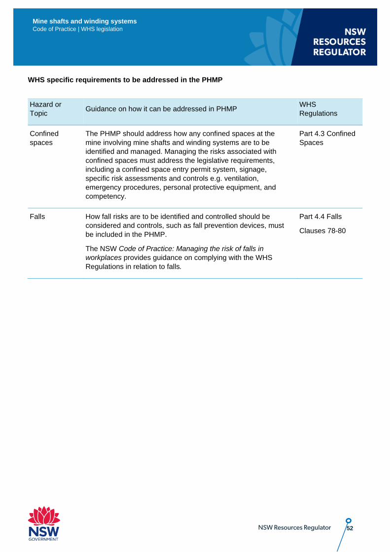
52 NSW Resources Regulator
Mine shafts and winding systems Code of Practice | WHS legislation
WHS specific requirements to be addressed in the PHMP
Hazard or Topic Guidance on how it can be addressed in PHMP WHS
Regulations
Confined spaces
The PHMP should address how any confined spaces at the mine involving mine shafts and winding systems are to be identified and managed. Managing the risks associated with confined spaces must address the legislative requirements, including a confined space entry permit system, signage, specific risk assessments and controls e.g. ventilation, emergency procedures, personal protective equipment, and competency.
Part 4.3 Confined Spaces
Falls
How fall risks are to be identified and controlled should be considered and controls, such as fall prevention devices, must be included in the PHMP.
The NSW Code of Practice: Managing the risk of falls in workplaces provides guidance on complying with the WHS Regulations in relation to falls.
Part 4.4 Falls
Clauses 78-80
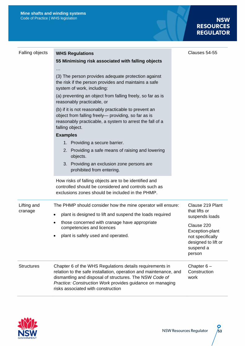
53 NSW Resources Regulator
Mine shafts and winding systems Code of Practice | WHS legislation
Falling objects WHS Regulations 55 Minimising risk associated with falling objects … (3) The person provides adequate protection against the risk if the person provides and maintains a safe system of work, including: (a) preventing an object from falling freely, so far as is reasonably practicable, or (b) if it is not reasonably practicable to prevent an object from falling freely— providing, so far as is reasonably practicable, a system to arrest the fall of a falling object. Examples
1. Providing a secure barrier. 2. Providing a safe means of raising and lowering
objects. 3. Providing an exclusion zone persons are
prohibited from entering.
How risks of falling objects are to be identified and controlled should be considered and controls such as exclusions zones should be included in the PHMP.
Clauses 54-55
Lifting and cranage
The PHMP should consider how the mine operator will ensure:
• plant is designed to lift and suspend the loads required
• those concerned with cranage have appropriate competencies and licences
• plant is safely used and operated.
Clause 219 Plant that lifts or suspends loads
Clause 220 Exception-plant not specifically designed to lift or suspend a person
Structures Chapter 6 of the WHS Regulations details requirements in relation to the safe installation, operation and maintenance, and dismantling and disposal of structures. The NSW Code of Practice: Construction Work provides guidance on managing risks associated with construction
Chapter 6 – Construction work
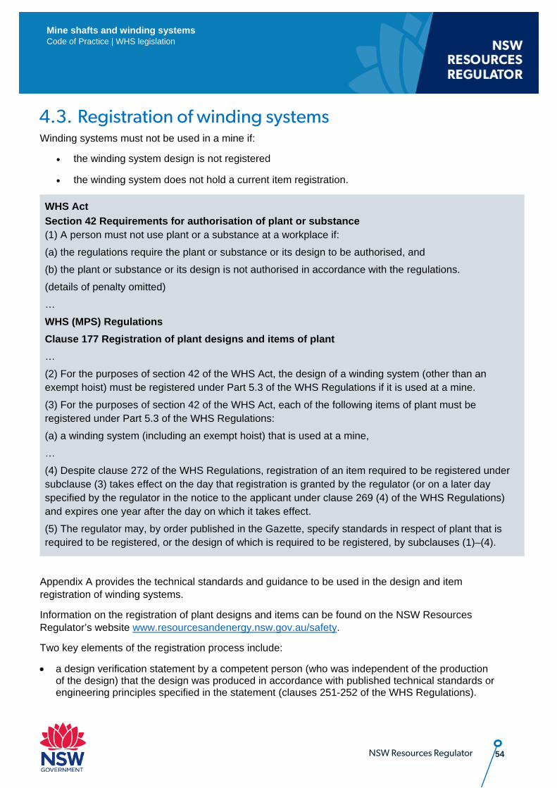
54 NSW Resources Regulator
Mine shafts and winding systems Code of Practice | WHS legislation
4.3. Registration of winding systems Winding systems must not be used in a mine if:
• the winding system design is not registered
• the winding system does not hold a current item registration.
WHS Act Section 42 Requirements for authorisation of plant or substance (1) A person must not use plant or a substance at a workplace if: (a) the regulations require the plant or substance or its design to be authorised, and (b) the plant or substance or its design is not authorised in accordance with the regulations. (details of penalty omitted) … WHS (MPS) Regulations Clause 177 Registration of plant designs and items of plant … (2) For the purposes of section 42 of the WHS Act, the design of a winding system (other than an exempt hoist) must be registered under Part 5.3 of the WHS Regulations if it is used at a mine. (3) For the purposes of section 42 of the WHS Act, each of the following items of plant must be registered under Part 5.3 of the WHS Regulations: (a) a winding system (including an exempt hoist) that is used at a mine, … (4) Despite clause 272 of the WHS Regulations, registration of an item required to be registered under subclause (3) takes effect on the day that registration is granted by the regulator (or on a later day specified by the regulator in the notice to the applicant under clause 269 (4) of the WHS Regulations) and expires one year after the day on which it takes effect. (5) The regulator may, by order published in the Gazette, specify standards in respect of plant that is required to be registered, or the design of which is required to be registered, by subclauses (1)–(4).
Appendix A provides the technical standards and guidance to be used in the design and item registration of winding systems.
Information on the registration of plant designs and items can be found on the NSW Resources Regulator’s website www.resourcesandenergy.nsw.gov.au/safety.
Two key elements of the registration process include:
• a design verification statement by a competent person (who was independent of the production of the design) that the design was produced in accordance with published technical standards or engineering principles specified in the statement (clauses 251-252 of the WHS Regulations).
55 NSW Resources Regulator
Mine shafts and winding systems Code of Practice | WHS legislation
• a statement by a competent person that the winding system has been inspected and assessed as being safe to operate (clause 266(2)(h) of the WHS Regulations).
The designer of the winding system must keep certain records:
WHS Regulations 228 Records and information If the design of plant is required to be registered under Part 5.3, the designer of that plant must make a record that contains: (a) the method used to determine the control measures for the plant and the control measures that result from that determination, and (b) a copy of the information provided to a manufacturer under section 22 of the Act in relation to that plant, and (c) a copy of the information provided to a manufacturer under clause 187 in relation to that plant, and (d) if applicable, a copy of the information provided to a manufacturer under clause 188 in relation to that plant. (details of penalty omitted)
5. Life cycle management The overall life cycle of plant and structures involves the following phases:
• design • manufacture • installation • commissioning • operation • inspection, testing and maintenance • decommissioning
The MECP and EECP address the general provisions for managing the life cycle of plant and structures at a mine. For further information refer to the NSW Code of Practice: Mechanical Engineering Control Plan and the NSW Code of Practice: Electrical Engineering Control Plan.
There are particular considerations for mine shafts and winding systems and how the mine operator may manage the winding system in compliance with the WHS legislated duties throughout the life cycle of the winding system. These considerations, together with other duty holder requirements, are covered below for each phase of the life cycle. Although the names of each life cycle phase may differ from those used in Appendix E – Function safety and its application to winding systems, the life cycle arrangements in Appendix E should apply.
56 NSW Resources Regulator
Mine shafts and winding systems Code of Practice | WHS legislation
The mine operator should conduct a risk assessment and consider the risk reduction strategy throughout the life cycle of the winding system. To develop a strategy, the mine operator should:
• consider the limits of the winding system including any foreseeable misuse • identify hazards and hazardous situations • estimate the risk for the identified hazards and hazardous situations • evaluate the risk and make the required decisions for risk reduction • eliminate the hazard or reduce the risk associated with the hazard using protective means.
5.1. Design The safe design of winding systems plays a critical role in eliminating hazards and risks before the winding system is introduced to the mine. Safe design applies to every phase in the winding system life cycle from conception to disposal. This means the hazards listed in this code should be considered and design solutions provided.
In designing the mine winding systems, consideration should be given to: • the purpose of the winding system and intended use and life (as specified by the mine operator) • the functional specification provided by the mine operator • required winding system operations, inspections, tests and maintenance • required shaft inspections, tests and maintenance • relevant technical standards • design risk assessments including:
• direct input from the mine operator to ensure any site-specific requirements are fully considered
• winding system site specific risk assessments • design operational risk assessments
• reasonably foreseeable misuse, including the use of the plant in a way not intended by the designer, but which can result from readily predictable human behaviour
• ensuring all design issues are adequately addressed, including the following: • ropes, sheaves, attachments, sheaves, drivelines, foundations, conveyances, skips • use of slope winding systems with people and materials • brakes, callipers and posts (their components and performance) • safety devices • hydraulic design • control system • application loads, power, winder drum, shaft, sheave, gearbox, couplings, foundations, drift
rails and guides • guide roller assembly • suspension • inspection of structures, foundations, winder house, headframe, landings, stages, sump
57 NSW Resources Regulator
Mine shafts and winding systems Code of Practice | WHS legislation
• safety devices generally • rails and rail maintenance issues (for drift winding systems) • relevant safety control devices are considered, with appropriate functional integrity. • brake control system
- brake wear indication - faulty or stuck valve indication - low hydraulic oil level - low system pressure - high temperature alarms including fire alarms - low level drum pit flood alarm
Further information on the design of winding systems may be found in the MDG 33 Winding System series of guidelines.
The winding system design must be independently verified by a competent person (who was not involved in the production of the design) that the design was produced in accordance with the published technical design standards as specified by the designer (clause 251 of the WHS Regulations). A copy of this design verification statement should be kept in the plant safety file at the mine (refer to 5.7 below).
5.2. Manufacture During the manufacturing process, the mine operator should conduct inspection and tests to validate the quality of the materials used and the manufacturing process. The inspections and tests should be conducted in accordance with the technical standards in Appendix A and may include:
• manufacture in accordance with the design information • material certification • material testing • destructive testing of sample processes • non-destructive testing • proof testing of components, apparatus and conveyances • independent review of test and inspections by a competent person.
5.3. Installation There should be an installation process, which includes relevant inspections and tests to validate the quality of the installation. The inspections and tests should be conducted in accordance with the technical standards in appendix A and may include:
• installation in accordance with the designers’ and manufacturers’ information • foundations and headframe structure with independent verification by a competent structural
engineer • winding systems installations • sheave

58 NSW Resources Regulator
Mine shafts and winding systems Code of Practice | WHS legislation
• rope cappings and attachments • safety devices such as jack catches, detaching hocks and bumpers • guide rails or ropes • guards and access platforms walkways.
The installation plan should also include a risk assessment on the installation. Particular consideration should be given to shaft work where people can fall. The winding system itself should not be used for installation unless it has commissioned and complies with the design.
The installation should be carried out under the direct supervision of suitably qualified mechanical and electrical engineers. Guidance in this regard is provided in 2.3.1 of the NSW Code of Practice: Electrical engineering control plan and the 4.3.3.1 of the NSW Code of Practice: Mechanical engineering control plan.
5.4. Commissioning There should be a commissioning process, which includes relevant inspections and tests to verify the winding system has been installed in accordance with the design documentation (see 5.1 above) and all safety devices are functional. The process should include:
• commissioning in accordance with the designers’ and manufacturers’ information • proof testing of the winding system • site function testing of all safety devices • static and dynamic testing of brakes to verify the full duty of the winding system • independent verification of the commissioning process by a competent person(s).
The mine operator should obtain a statement signed by a competent person (such as, mechanical and electrical engineer) that the winding system is safe to use.
5.5. Operation The winding system should be operated in accordance with the designers’ and manufacturers’ information. The PHMP should address the requirements in Chapters 1 to 3 of this code. The PHMP should be implemented before the winding system is operated for its intended use.
5.6. Installation, testing and maintenance The winding system should be inspected, tested and maintained in accordance with the designers’ and manufacturers’ information or as required by WHS laws. The shaft and winding system should be subject to a maintenance management system which includes:
• pre-operational inspections, tests and maintenance • periodic or condition based servicing or both • periodic inspections • inspection and testing of safety systems and safety equipment • isolation and energy dissipation • records • training, including knowledge of accepted designer or manufacturer requirements • compliance audition
59 NSW Resources Regulator
Mine shafts and winding systems Code of Practice | WHS legislation
• the competency of workers • change management • defect management.
The maintenance, inspection and testing (including, frequency) must be carried out in accordance with clause 213 of the WHS Regulations.
WHS Regulations 213 Maintenance and inspection of plant (1) The person with management or control of plant at a workplace must ensure that the
maintenance, inspection and, if necessary, testing of the plant is carried out by a competent person.
(details of penalty omitted) (2) The maintenance, inspection and testing must be carried out: (a) in accordance with the manufacturer’s recommendations, if any, or (b) if there are no manufacturer’s recommendations, in accordance with the recommendations of a competent person, or (c) in relation to inspection, if it is not reasonably practicable to comply with paragraph (a) or (b), annually.
There should be yearly verification by a competent person that the winding system has been maintained and is safe to use. This should be documented.
5.7. Life cycle documentation – plant safety file A plant safety file that covers the life cycle of the winding system should be kept for the life of the mine shaft and winding system.
The plant safety file should be initiated in the first stage of the life cycle (concept design) and it should be kept at the mine and maintained by the mine operator.
The safety related aspects of mine shafts and winding systems should be fully documented. A functional safety management plan may be used to assist in the management of the plant safety file. Guidance on the management of information regarding safety-related systems and functions may be found in Appendix E and the AS 61508 Functional safety of electrical/electronic/programmable electronic safety-related systems series of standards.
Part 5.3 of Chapter 5 of the WHS Regulations requires certain records to be kept for winding systems.
The following records should be maintained as part of a winding system safety file:
a) design specifications, performance, functions, condition and assumptions b) design documentation for registration c) information supplied by the designer, manufacturer and supplier d) hazard identification and risk assessment documents
60 NSW Resources Regulator
Mine shafts and winding systems Code of Practice | WHS legislation
e) risk control methods f) consultation records g) information required to enable implementation of the functional safety management plan,
including identification of all safety critical systems, and their safety category or integrity level h) component certifications and test certificates i) commissioning and test results j) maintenance records, safety inspections and test reports k) defects management system l) change of procedures, monitoring, audit and review reports m) reports of accidents, incidents and safety statistics n) training and competency records o) winding system modifications or alterations p) verification documentation q) emergency procedures.
The records should be stored and maintained in such a way that they are readily retrievable and protected against damage, deterioration or loss.
A plant safety file may not necessarily be a single document containing all records, but it may refer to different locations where the information can be obtained.
6. Monitoring, periodic review and audit 6.1. Monitoring Monitoring helps determine whether control measures are adequately designed, properly executed and effective at any given point in time. If controls are not effective for managing the risks, then the PHMP for mine shafts and winding systems should direct how they are to be corrected.
Monitoring is important to determine if there are any out of specification changes resulting in risks such as overspeed, overwind, etc.
Monitoring is also intended to avoid unwanted events by identifying potential problems, including changes to a hazard, hazard-related conditions or the effectiveness of controls.
The PHMP for mine shafts and winding systems should detail the frequency and type of monitoring such as inspections, assessments and audits. For each element of what the PHMP covers, including controls, monitoring activities should be identified and incorporated into the plan. Monitoring activities may include:
• pre-start inspections • visual inspections • internal inspections • function testing. There are different ways of monitoring PHs, including, monitoring: • the status of the hazard (for example, travel, braking, pressure, etc) • the mechanisms by which the unwanted event may occur (for example, failure of brakes or
communication systems etc) and/or • the status of key controls (for example, inspections, testing, etc).
61 NSW Resources Regulator
Mine shafts and winding systems Code of Practice | WHS legislation
Some examples of monitoring for the various types of winding system hazards include: • electronic references, for example, speed distance profile • monitoring door interlock to ensure effective guarding is in place • monitoring of ropes to ensure they are within the specification limits • monitoring shaft condition. The PHMP should identify the frequency of the different monitoring activities and incorporate these into the plan. Inspections may occur on a frequent basis, per shift, daily, weekly and so on. In contrast, a formal audit and review process is less frequent and periodic, often to a set schedule (see 6.4 below for further details). The PHMP should identify the required skills and competencies for people undertaking the different monitoring activities.
6.2. Review of control measures The mine operator must review and revise the risk control measures provided for the in PHMP for the mine shafts and winding systems in certain circumstances, as required in clause 38 of the WHS Regulations and clause 10 of the WHS (MPS) Regulations.
6.3. Periodic review The mine operator must ensure the PHMP for mine shafts and winding systems is reviewed in accordance with the WHS (MPS) Regulations.
WHS (MPS) Regulations
25 Review (cl 629 model WHS Regs)
(1) The operator of a mine or petroleum site must ensure that a principal hazard management plan is reviewed and as necessary revised if a control measure specified in the plan is revised under clause 38 of the WHS Regulations or clause 10 of this Regulation.
(details of penalty omitted) Note. A principal hazard management plan is part of the safety management system for a mine or petroleum site (see clause 14 (1) (c) (i)), which must be audited under clause 15, maintained under clause 16 and reviewed and as necessary revised under clause 17. (2) If a principal hazard management plan is revised, the operator must record the revisions, including any revision of a risk assessment, in writing in the plan. (details of penalty omitted)
The purpose of a review is to determine if the PHMP for mine shafts and winding systems is effective in managing the hazards posed by mine shafts and winding systems and not just whether the plan is being carried out. Further information on the review of risk control measures in provided in 2.6 of the code above.
The PHMP for mine shafts and winding systems must also be reviewed as part of the Safety Management System for the mine:
62 NSW Resources Regulator
Mine shafts and winding systems Code of Practice | WHS legislation
WHS (MPS) Regulations
17 Review (cl 625 model WHS Regs)
(1) The operator of a mine or petroleum site must ensure that the safety management system for the mine or petroleum site is reviewed within 12 months of the commencement of mining operations or petroleum operations at the mine or petroleum site and at least once every 3 years after that to ensure it remains effective.
(details of penalty omitted) (2) In addition, if a control measure is revised under clause 38 of the WHS Regulations or
clause 10 of this Regulation, the operator must ensure that the safety management system for the mine or petroleum site is reviewed and as necessary revised in relation to all aspects of risk control addressed by the revised control measure.
(details of penalty omitted)
In the first part of the review, the underpinning risk assessment should be reviewed to see whether it is still appropriate to the hazards at the mine.
In undertaking a review, the mine’s workers and their health and safety representatives (and mine safety and health representatives in coal mines) must be consulted, as required under the WHS laws. The following questions, during that consultation, should be considered by the mine operator and workers:
• Are all risks posed by the mine shafts and winding systems adequately managed? • Are control measures working effectively in both their design and operation? • Are the relevant workers aware of the control measures and do they understand them? • How effective is the risk assessment process? Are all hazards being identified? • Have new work methods or new plant been introduced to make the job safer? What is their
impact on existing hazards, risks and control measures? • Are safety procedures being followed? • Has instruction and training provided to workers been successful? • If new legislation or information becomes available, does it warrant a review of current controls? • What has been the industry experience with respect to shafts and winding systems since the last
review? • Have any incidents occurred in relation to the winding system and what are the outcomes or
trends identified from them? • What are the current industry best practices for compliance (and better) and whether any
activities have been benchmarked against them? • Have there been technological advances that may be of assistance in managing risks posed by
mine shafts and winding systems? • Whether there have there been any industry publications or technical reports published that may
assist in managing risks posed by mine shafts and winding systems? • Have there been any relevant incidents and what were the outcomes of investigations?
63 NSW Resources Regulator
Mine shafts and winding systems Code of Practice | WHS legislation
If problems are found, the mine operator should review current information and make further decisions about risk controls to be implemented through the PHMP.
Further information on the frequency of inspection, testing and maintenance of winding systems may can be found in 5.6 of the code above.
6.4. Audit The WHS (MPS) Regulations require the mine operator to carry out audits of the PHMP for the mine shafts and winding systems:
WHS (MPS) Regulations
15 Performance standards and audit (cl 623 model WHS Regs)
The safety management system for a mine or petroleum site must include the following: (a) performance standards for measuring the effectiveness of all aspects of the safety management system that: (i) are sufficiently detailed to show how the operator will ensure the effectiveness of the safety management system, and (ii) include steps to be taken to continually improve the safety management system, (b) the way in which the performance standards are to be met, (c) a system for auditing the effectiveness of the safety management system for the mine or petroleum site against the performance standards, including the methods, frequency and results of the audit process.
The mine operator must set performance standards and audit against them, such as whether procedures specified are in place and being followed, performance outcomes set are being achieved, and actions (for example corrective actions from an incident investigation) are being taken. Further details on auditing are contained in the NSW Code of Practice: Safety management systems in mines.
The purpose of the audit is to measure the effectiveness of the PHMP for mine shafts and winding systems against set performance standards and may include the following:
• mine workers understand their responsibilities and carry them out • training and testing has been carried out in accordance with the PHMP • plant and installations required is fit for purpose, available and maintained • inspections and tests specified have been carried out • corrective actions have been carried out, such as a predefined response to a trigger under a
TARP • required reports have been completed. Information from the audit should enable the PHMP to be improved and for it to remain effective in managing the risks posed by mine shafts and winding systems at the mine.
The mine operator should develop an audit plan for the PHMP, as part of the SMS.
64 NSW Resources Regulator
Mine shafts and winding systems Code of Practice | WHS legislation
The audit system must include the frequency, audit methodology and results. It may also include provisions for:
• scope of the audit • name(s) and competency of the auditor(s) • person responsible for ensuring the audit is conducted • reporting protocol or outcomes for the audit • person(s) responsible for acting on the audit report • corporate or PCBU requirements for auditing, such as internal versus external auditors. One performance standard that should be included in the audit plan is for the audit to find 100% compliance with legislation.
There should be safety assessments and reviews of winding systems every five years. The audit is typically known as ‘the safety audit’. The purpose is to independently verify:
• the winding system is operating within the specified design specifications and that it has not been altered
• the operation, servicing, testing and maintenance of the winding system • the PHMP for mine shaft and winding systems is adequate and is being followed.
MDG 33.1 Guidelines for the design, commissioning and maintenance of drum winders – General requirement also provides guidance on some of the items which should be covered in the safety audit.
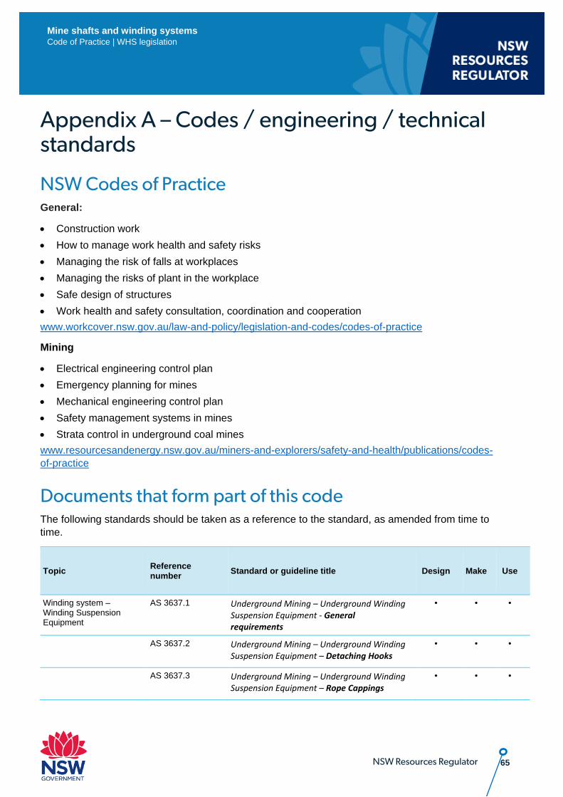
65 NSW Resources Regulator
Mine shafts and winding systems Code of Practice | WHS legislation
Appendix A – Codes / engineering / technical standards
NSW Codes of Practice General:
• Construction work • How to manage work health and safety risks • Managing the risk of falls at workplaces • Managing the risks of plant in the workplace • Safe design of structures • Work health and safety consultation, coordination and cooperation www.workcover.nsw.gov.au/law-and-policy/legislation-and-codes/codes-of-practice
Mining
• Electrical engineering control plan • Emergency planning for mines • Mechanical engineering control plan • Safety management systems in mines • Strata control in underground coal mines www.resourcesandenergy.nsw.gov.au/miners-and-explorers/safety-and-health/publications/codes-of-practice
Documents that form part of this code The following standards should be taken as a reference to the standard, as amended from time to time.
Topic Reference number Standard or guideline title Design Make Use
Winding system – Winding Suspension Equipment
AS 3637.1 Underground Mining – Underground Winding Suspension Equipment - General requirements
• • •
AS 3637.2 Underground Mining – Underground Winding Suspension Equipment – Detaching Hooks
• • •
AS 3637.3 Underground Mining – Underground Winding Suspension Equipment – Rope Cappings
• • •
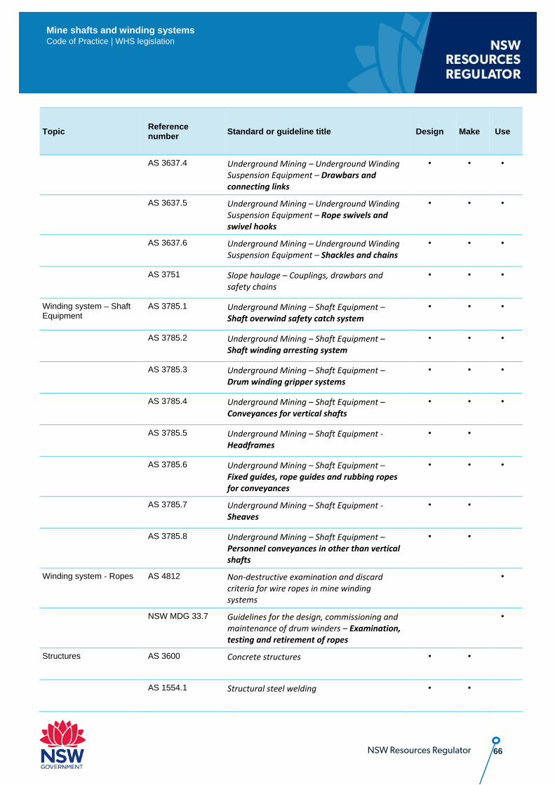
66 NSW Resources Regulator
Mine shafts and winding systems Code of Practice | WHS legislation
Topic Reference number Standard or guideline title Design Make Use
AS 3637.4 Underground Mining – Underground Winding Suspension Equipment – Drawbars and connecting links
• • •
AS 3637.5 Underground Mining – Underground Winding Suspension Equipment – Rope swivels and swivel hooks
• • •
AS 3637.6 Underground Mining – Underground Winding Suspension Equipment – Shackles and chains
• • •
AS 3751 Slope haulage – Couplings, drawbars and safety chains
• • •
Winding system – Shaft Equipment
AS 3785.1 Underground Mining – Shaft Equipment – Shaft overwind safety catch system
• • •
AS 3785.2 Underground Mining – Shaft Equipment – Shaft winding arresting system
• • •
AS 3785.3 Underground Mining – Shaft Equipment – Drum winding gripper systems
• • •
AS 3785.4 Underground Mining – Shaft Equipment – Conveyances for vertical shafts
• • •
AS 3785.5 Underground Mining – Shaft Equipment - Headframes
• •
AS 3785.6 Underground Mining – Shaft Equipment – Fixed guides, rope guides and rubbing ropes for conveyances
• • •
AS 3785.7 Underground Mining – Shaft Equipment - Sheaves
• •
AS 3785.8 Underground Mining – Shaft Equipment – Personnel conveyances in other than vertical shafts
• •
Winding system - Ropes AS 4812 Non-destructive examination and discard criteria for wire ropes in mine winding systems
•
NSW MDG 33.7 Guidelines for the design, commissioning and maintenance of drum winders – Examination, testing and retirement of ropes
•
Structures AS 3600 Concrete structures • •
AS 1554.1 Structural steel welding • •
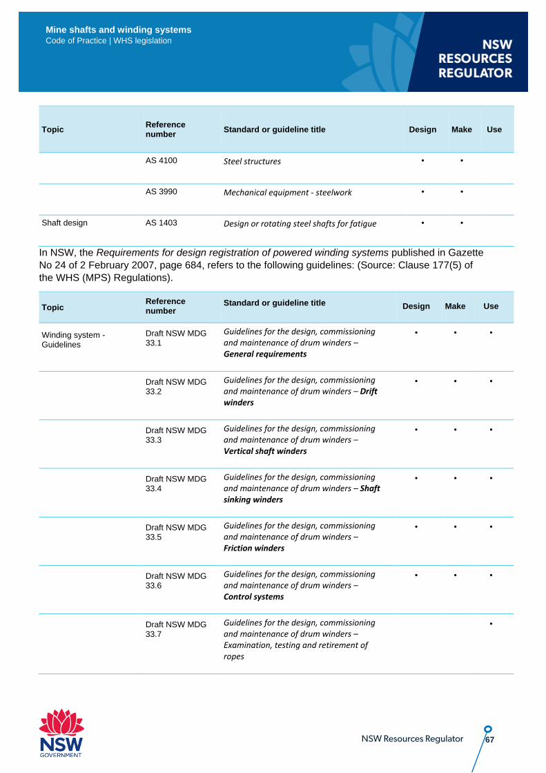
67 NSW Resources Regulator
Mine shafts and winding systems Code of Practice | WHS legislation
Topic Reference number Standard or guideline title Design Make Use
AS 4100 Steel structures • •
AS 3990 Mechanical equipment - steelwork • •
Shaft design AS 1403 Design or rotating steel shafts for fatigue • •
In NSW, the Requirements for design registration of powered winding systems published in Gazette No 24 of 2 February 2007, page 684, refers to the following guidelines: (Source: Clause 177(5) of the WHS (MPS) Regulations).
Topic Reference number
Standard or guideline title Design Make Use
Winding system - Guidelines
Draft NSW MDG 33.1
Guidelines for the design, commissioning and maintenance of drum winders – General requirements
• • •
Draft NSW MDG 33.2
Guidelines for the design, commissioning and maintenance of drum winders – Drift winders
• • •
Draft NSW MDG 33.3
Guidelines for the design, commissioning and maintenance of drum winders – Vertical shaft winders
• • •
Draft NSW MDG 33.4
Guidelines for the design, commissioning and maintenance of drum winders – Shaft sinking winders
• • •
Draft NSW MDG 33.5
Guidelines for the design, commissioning and maintenance of drum winders – Friction winders
• • •
Draft NSW MDG 33.6
Guidelines for the design, commissioning and maintenance of drum winders – Control systems
• • •
Draft NSW MDG 33.7
Guidelines for the design, commissioning and maintenance of drum winders – Examination, testing and retirement of ropes
•
68 NSW Resources Regulator
Mine shafts and winding systems Code of Practice | WHS legislation
Guidance on the registration of winding system designs and items can be found at www.resourcesandenergy.nsw.gov.au/miners-and-explorers/safety-and-health/applications/registration-and-licensing
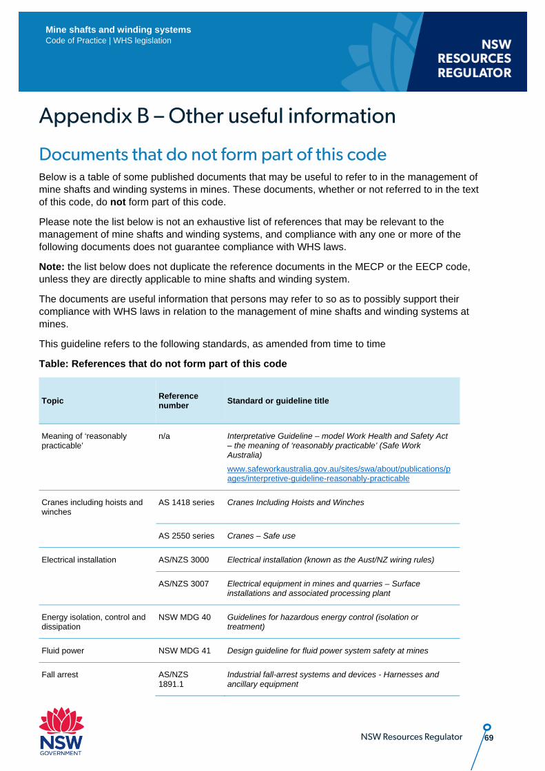
69 NSW Resources Regulator
Mine shafts and winding systems Code of Practice | WHS legislation
Appendix B – Other useful information
Documents that do not form part of this code Below is a table of some published documents that may be useful to refer to in the management of mine shafts and winding systems in mines. These documents, whether or not referred to in the text of this code, do not form part of this code.
Please note the list below is not an exhaustive list of references that may be relevant to the management of mine shafts and winding systems, and compliance with any one or more of the following documents does not guarantee compliance with WHS laws.
Note: the list below does not duplicate the reference documents in the MECP or the EECP code, unless they are directly applicable to mine shafts and winding system.
The documents are useful information that persons may refer to so as to possibly support their compliance with WHS laws in relation to the management of mine shafts and winding systems at mines.
This guideline refers to the following standards, as amended from time to time
Table: References that do not form part of this code
Topic Reference number Standard or guideline title
Meaning of ‘reasonably practicable’
n/a Interpretative Guideline – model Work Health and Safety Act – the meaning of ‘reasonably practicable’ (Safe Work Australia)
www.safeworkaustralia.gov.au/sites/swa/about/publications/pages/interpretive-guideline-reasonably-practicable
Cranes including hoists and winches
AS 1418 series Cranes Including Hoists and Winches
AS 2550 series Cranes – Safe use
Electrical installation AS/NZS 3000 Electrical installation (known as the Aust/NZ wiring rules)
AS/NZS 3007 Electrical equipment in mines and quarries – Surface installations and associated processing plant
Energy isolation, control and dissipation
NSW MDG 40 Guidelines for hazardous energy control (isolation or treatment)
Fluid power NSW MDG 41 Design guideline for fluid power system safety at mines
Fall arrest AS/NZS 1891.1
Industrial fall-arrest systems and devices - Harnesses and ancillary equipment
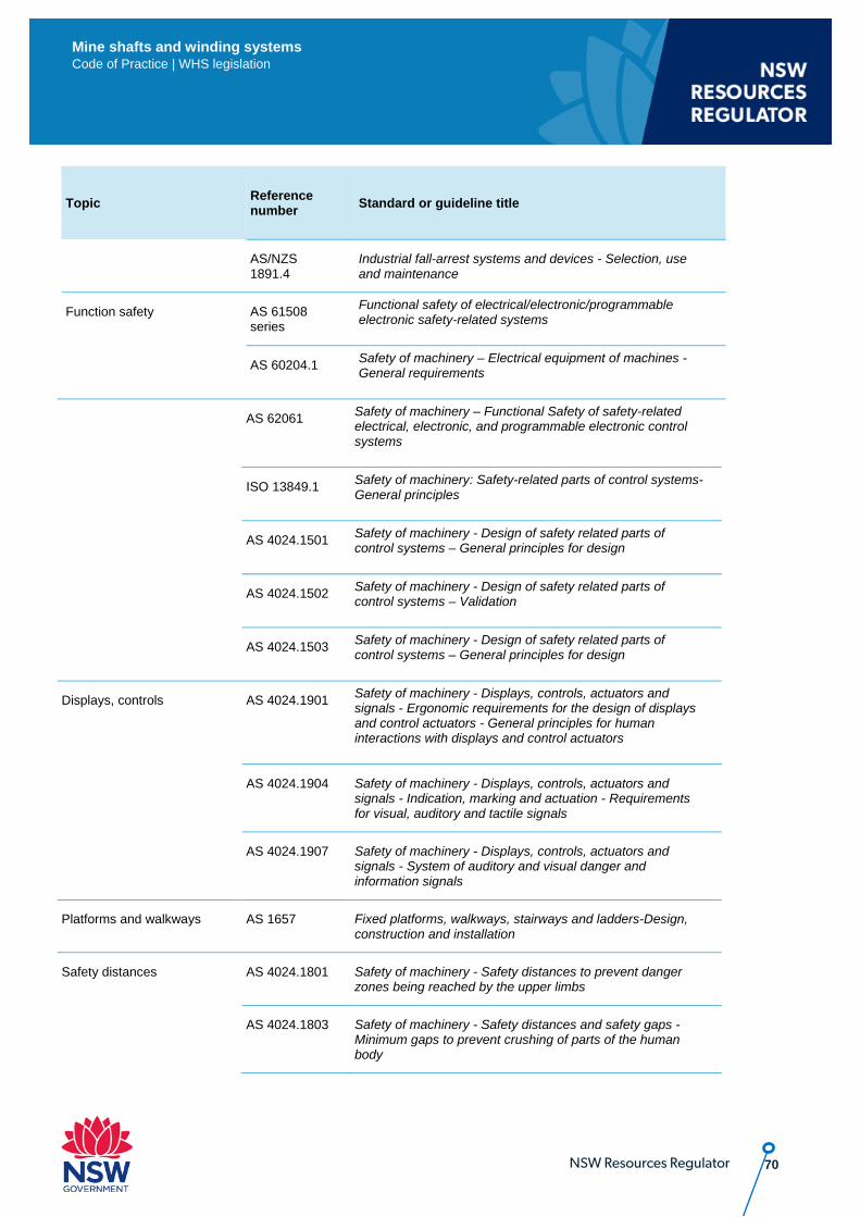
70 NSW Resources Regulator
Mine shafts and winding systems Code of Practice | WHS legislation
Topic Reference number Standard or guideline title
AS/NZS 1891.4
Industrial fall-arrest systems and devices - Selection, use and maintenance
Function safety AS 61508 series
Functional safety of electrical/electronic/programmable electronic safety-related systems
AS 60204.1 Safety of machinery – Electrical equipment of machines - General requirements
AS 62061 Safety of machinery – Functional Safety of safety-related electrical, electronic, and programmable electronic control systems
ISO 13849.1 Safety of machinery: Safety-related parts of control systems-General principles
AS 4024.1501 Safety of machinery - Design of safety related parts of control systems – General principles for design
AS 4024.1502 Safety of machinery - Design of safety related parts of control systems – Validation
AS 4024.1503 Safety of machinery - Design of safety related parts of control systems – General principles for design
Displays, controls AS 4024.1901 Safety of machinery - Displays, controls, actuators and signals - Ergonomic requirements for the design of displays and control actuators - General principles for human interactions with displays and control actuators
AS 4024.1904 Safety of machinery - Displays, controls, actuators and signals - Indication, marking and actuation - Requirements for visual, auditory and tactile signals
AS 4024.1907 Safety of machinery - Displays, controls, actuators and signals - System of auditory and visual danger and information signals
Platforms and walkways AS 1657 Fixed platforms, walkways, stairways and ladders-Design, construction and installation
Safety distances AS 4024.1801 Safety of machinery - Safety distances to prevent danger zones being reached by the upper limbs
AS 4024.1803 Safety of machinery - Safety distances and safety gaps - Minimum gaps to prevent crushing of parts of the human body
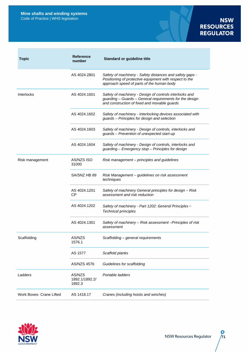
71 NSW Resources Regulator
Mine shafts and winding systems Code of Practice | WHS legislation
Topic Reference number Standard or guideline title
AS 4024.2801 Safety of machinery - Safety distances and safety gaps - Positioning of protective equipment with respect to the approach speed of parts of the human body
Interlocks AS 4024.1601 Safety of machinery - Design of controls interlocks and guarding – Guards – General requirements for the design and construction of fixed and movable guards
AS 4024.1602 Safety of machinery - Interlocking devices associated with guards – Principles for design and selection
AS 4024.1603 Safety of machinery - Design of controls, interlocks and guards – Prevention of unexpected start-up
AS 4024.1604 Safety of machinery - Design of controls, interlocks and guarding – Emergency stop – Principles for design
Risk management AS/NZS ISO 31000
Risk management – principles and guidelines
SA/SNZ HB 89 Risk Management – guidelines on risk assessment techniques
AS 4024.1201 CP
Safety of machinery General principles for design – Risk assessment and risk reduction
AS 4024.1202 Safety of machinery - Part 1202: General Principles – Technical principles
AS 4024.1301 Safety of machinery – Risk assessment –Principles of risk assessment
Scaffolding AS/NZS 1576.1
Scaffolding – general requirements
AS 1577 Scaffold planks
AS/NZS 4576 Guidelines for scaffolding
Ladders AS/NZS 1892.1/1892.2/1892.3
Portable ladders
Work Boxes- Crane Lifted AS 1418.17 Cranes (including hoists and winches)
72 NSW Resources Regulator
Mine shafts and winding systems Code of Practice | WHS legislation
Topic Reference number Standard or guideline title
Fatigue 2018 Ver 1.1 Guide – Fatigue management – Guidance for the NSW mining and petroleum Available from
https://www.resourcesandgeoscience.nsw.gov.au/__data/assets/pdf_file/0008/805688/Fatigue-Management-Guide-FINAL-for-publication.pdf
73 NSW Resources Regulator
Mine shafts and winding systems Code of Practice | WHS legislation
Appendix C – Rope factor of safety (FOS) AS 4812 Non-destructive examination and discard criteria for wire ropes in mine winding systems and MDG 33.7 Guidelines for the design, commissioning and maintenance of drum winders – Examination, testing and retirement of ropes provides further guidance on rope FOS and discard criteria.
Rope breaking force The rope breaking force is used for calculating the rope FOS for the winding system installation. It should be the lesser of either:
• the minimum design breaking force for the rope when newly installed, or • the actual breaking force of the rope when new.
Drift drum winder rope FOS – transport of people It is calculated by dividing the breaking force of the rope by the sum of the maximum load to be raised or lowered by the rope, plus the total mass of the rope acting as load due to gravity when fully let out.
The following factors of safety for drift drum winder ropes apply to the transport of people.
Ropes, when newly installed should have a FOS of not less than 10. The rope should be discarded when either:
a) the FOS falls below 8 as identified by testing; b) there is a loss of breaking strength of greater than 10% of the strength in the as-new
condition; or c) the discard criteria in AS 4812 is exceeded.
Vertical shaft drum winder rope FOS It is calculated by dividing the breaking force of the rope by the sum of the maximum load to be raised or lowered by the rope, plus the total mass of rope acting as load due to gravity when fully let out.
The factors of safety for drum winder ropes should:
a) satisfy the criteria in the table below, and
b) not be less than 6.0:1, where the safety of personnel is involved, unless justified by a detailed engineering dynamic analysis and the winder control system continuously monitors dynamic forces in the rope.
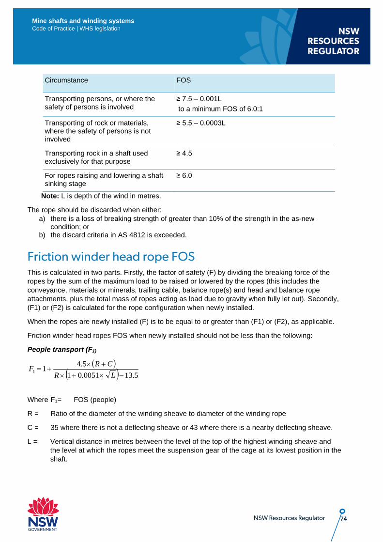
74 NSW Resources Regulator
Mine shafts and winding systems Code of Practice | WHS legislation
Circumstance FOS
Transporting persons, or where the safety of persons is involved
≥ 7.5 – 0.001L to a minimum FOS of 6.0:1
Transporting of rock or materials, where the safety of persons is not involved
≥ 5.5 – 0.0003L
Transporting rock in a shaft used exclusively for that purpose
≥ 4.5
For ropes raising and lowering a shaft sinking stage
≥ 6.0
Note: L is depth of the wind in metres.
The rope should be discarded when either: a) there is a loss of breaking strength of greater than 10% of the strength in the as-new
condition; or b) the discard criteria in AS 4812 is exceeded.
Friction winder head rope FOS This is calculated in two parts. Firstly, the factor of safety (F) by dividing the breaking force of the ropes by the sum of the maximum load to be raised or lowered by the ropes (this includes the conveyance, materials or minerals, trailing cable, balance rope(s) and head and balance rope attachments, plus the total mass of ropes acting as load due to gravity when fully let out). Secondly, (F1) or (F2) is calculated for the rope configuration when newly installed.
When the ropes are newly installed (F) is to be equal to or greater than (F1) or (F2), as applicable.
Friction winder head ropes FOS when newly installed should not be less than the following:
People transport (F1)
Where F1= FOS (people)
R = Ratio of the diameter of the winding sheave to diameter of the winding rope
C = 35 where there is not a deflecting sheave or 43 where there is a nearby deflecting sheave.
L = Vertical distance in metres between the level of the top of the highest winding sheave and the level at which the ropes meet the suspension gear of the cage at its lowest position in the shaft.
( )( ) 5.130051.01
5.411 −×+×+×
+=LR
CRF
75 NSW Resources Regulator
Mine shafts and winding systems Code of Practice | WHS legislation
Head ropes The rope should be discarded when the discard criteria in AS 4812 is exceeded.
Friction winder balance rope FOS The friction winder balance rope FOS is not to be less than 6.
The rope should be discarded when the discard criteria in AS 4812 is exceeded.
Guide ropes and rubbing ropes Every guide rope and rubbing rope used at a mine should, when newly installed, have a breaking force of not less than 5 times the heaviest static load to which the rope may be subjected. The rope should be discarded when the discard criteria in AS 4812 is exceeded.
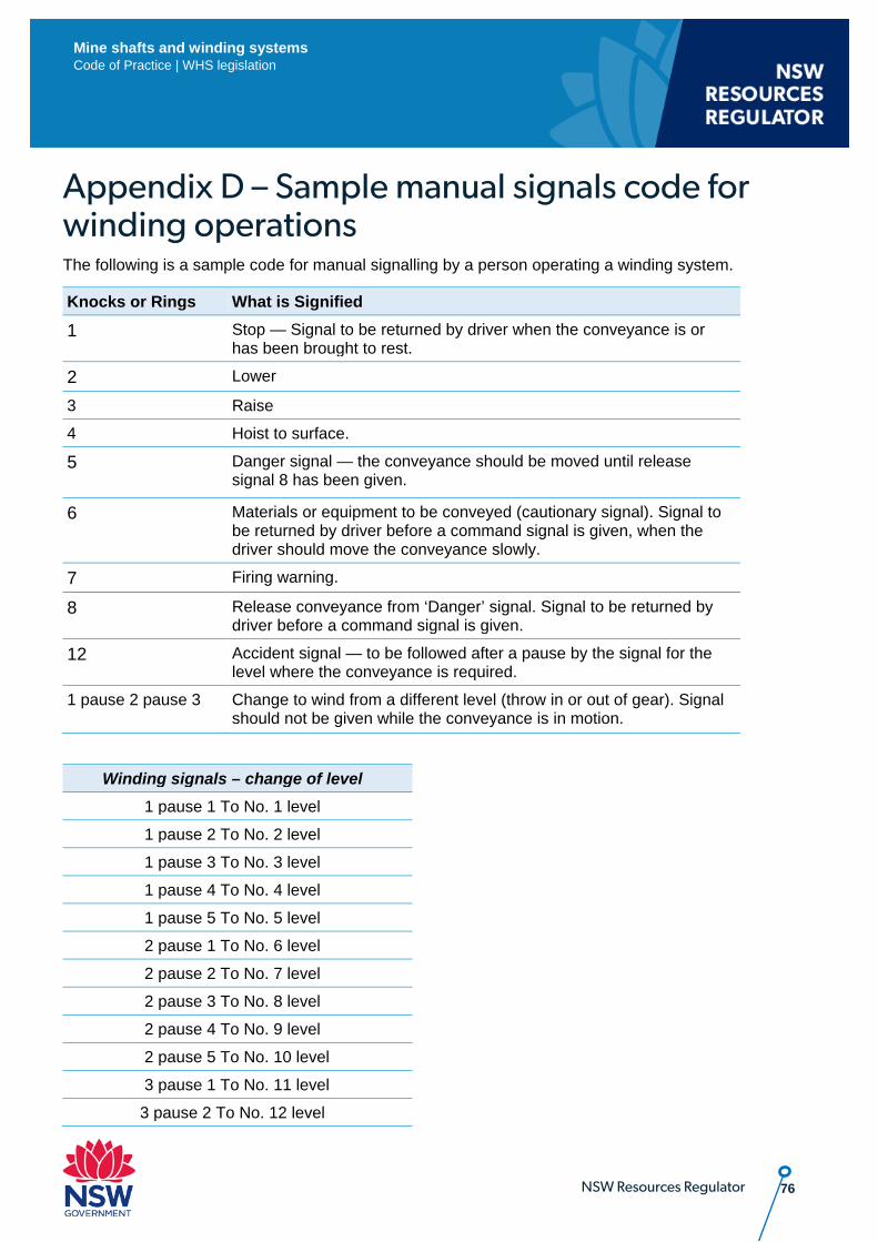
76 NSW Resources Regulator
Mine shafts and winding systems Code of Practice | WHS legislation
Appendix D – Sample manual signals code for winding operations The following is a sample code for manual signalling by a person operating a winding system.
Knocks or Rings What is Signified
1 Stop — Signal to be returned by driver when the conveyance is or has been brought to rest.
2 Lower
3 Raise
4 Hoist to surface.
5 Danger signal — the conveyance should be moved until release signal 8 has been given.
6 Materials or equipment to be conveyed (cautionary signal). Signal to be returned by driver before a command signal is given, when the driver should move the conveyance slowly.
7 Firing warning.
8 Release conveyance from ‘Danger’ signal. Signal to be returned by driver before a command signal is given.
12 Accident signal — to be followed after a pause by the signal for the level where the conveyance is required.
1 pause 2 pause 3 Change to wind from a different level (throw in or out of gear). Signal should not be given while the conveyance is in motion.
Winding signals – change of level 1 pause 1 To No. 1 level
1 pause 2 To No. 2 level
1 pause 3 To No. 3 level
1 pause 4 To No. 4 level
1 pause 5 To No. 5 level
2 pause 1 To No. 6 level
2 pause 2 To No. 7 level
2 pause 3 To No. 8 level
2 pause 4 To No. 9 level
2 pause 5 To No. 10 level
3 pause 1 To No. 11 level
3 pause 2 To No. 12 level
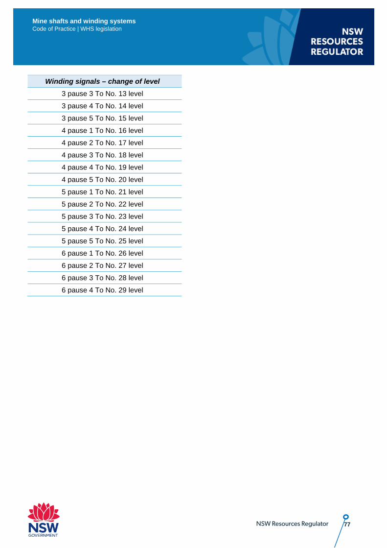
77 NSW Resources Regulator
Mine shafts and winding systems Code of Practice | WHS legislation
Winding signals – change of level 3 pause 3 To No. 13 level
3 pause 4 To No. 14 level
3 pause 5 To No. 15 level
4 pause 1 To No. 16 level
4 pause 2 To No. 17 level
4 pause 3 To No. 18 level
4 pause 4 To No. 19 level
4 pause 5 To No. 20 level
5 pause 1 To No. 21 level
5 pause 2 To No. 22 level
5 pause 3 To No. 23 level
5 pause 4 To No. 24 level
5 pause 5 To No. 25 level
6 pause 1 To No. 26 level
6 pause 2 To No. 27 level
6 pause 3 To No. 28 level
6 pause 4 To No. 29 level
78 NSW Resources Regulator
Mine shafts and winding systems Code of Practice | WHS legislation
Appendix E – Functional safety and application to winding systems
Introduction The following information covers how functional safety may be applied to the life cycle arrangements of winding systems. It is assumed that the reader has a working understanding of functional safety.
Functional safety is the part of overall plant safety that depends on safety-related systems operating correctly.
A safety-related system is designed to prevent the machine going into a dangerous state by taking action on detecting a condition that may lead to a hazardous event.
A safety-related system is comprised of a number of safety functions whose purpose is to detect potentially dangerous condition(s) through input sensors, process the event and automatically activate a protective or corrective device, thereby preventing the hazardous event.
An example of a safety function commonly seen on a winding system is over speed protection. The safety-related system would compromise all components required to enact this function, including:
• the encoder or speed sensing device • the processor monitoring the speed input for the unsafe condition and triggering a response • the emergency braking system engaged by the processor to stop the winding system. Although the electronic system is a key component of the overall winding system, the mechanical interfaces to the sensors and braking system should be considered as part of the safety-related system concept and design process.
Comprehensive guidance on the design of the safety related parts of machine control systems, (including functional safety) may be found in:
• AS 61508 Functional safety of electrical/electronic/programmable electronic safety-related systems series of standards, and
• AS 62061 Safety of machinery – Functional safety of safety-related electrical, electronic and programmable electronic control systems.
Implementation and responsibility Functional safety standards require a full life cycle approach (i.e. from concept design to disposal) and share common phases in their implementation. To accomplish implementation, a functional safety management framework should be established.
Functional safety management (FSM) defines all activities required during the safety life cycle phases of a product or machine that are necessary for the achievement of the required level of functional safety. FSM also specifies the persons, departments and organisations responsible for each safety life cycle phase or for activities within each phase.
79 NSW Resources Regulator
Mine shafts and winding systems Code of Practice | WHS legislation
The core element associated with the management of functional safety is the creation of a Functional Safety Management Plan (FMSP). This Appendix E provides a road map to the FSMP.
Essential elements, such as the management of competence and configuration management, should be included in the FSMPs.
A competency management system should be developed. The required competencies for each role should be defined. The competencies of individuals allocated to a role should be assessed to ensure they meet the defined requirements.
An effective configuration management system ensures the configuration of the system can be identified at key milestones and recreated, if required. A functioning configuration management system should be implemented as early as practicable to ensure the deployed system is known and can be recreated, if required.
In general, regardless of standards chosen, the functional safety life cycle will include the following phases:
Generate a functional safety management plan (FSMP) The FSMP defines and documents the overall plan to achieve functional safety throughout the life cycle of the machine. It should define all required activities or procedures and allocate a responsible person or organisation (for example, the supplier). Each participant in the winding system life cycle (for example, the end user, designer, and supplier) will be required to generate a FSMP for their phase of work.
Analysis phase In this phase, all hazards are identified, and associated risks assessed as per the steps outlined in the section below titled ‘Consideration of Functional Safety for a Winding System’. This task may overlap with the requirements for a PHMP by the mine operator (clauses 23 to 24 of the WHS (MPS) Regulations). The duty holder normally maintains responsibility for the analysis phase with input from suppliers or consultants, as required.
Specification phase This phase links the analysis phase to the design phase and is often used as a handover point to the supplier. The requirements for the safety-related system are clearly defined and documented, at a minimum detailing the required safety function(s) and the corresponding integrity they should achieve. The specification phase is generally driven by the end user or the mine operator, with input from suppliers or consultants, as required.
Realisation/design
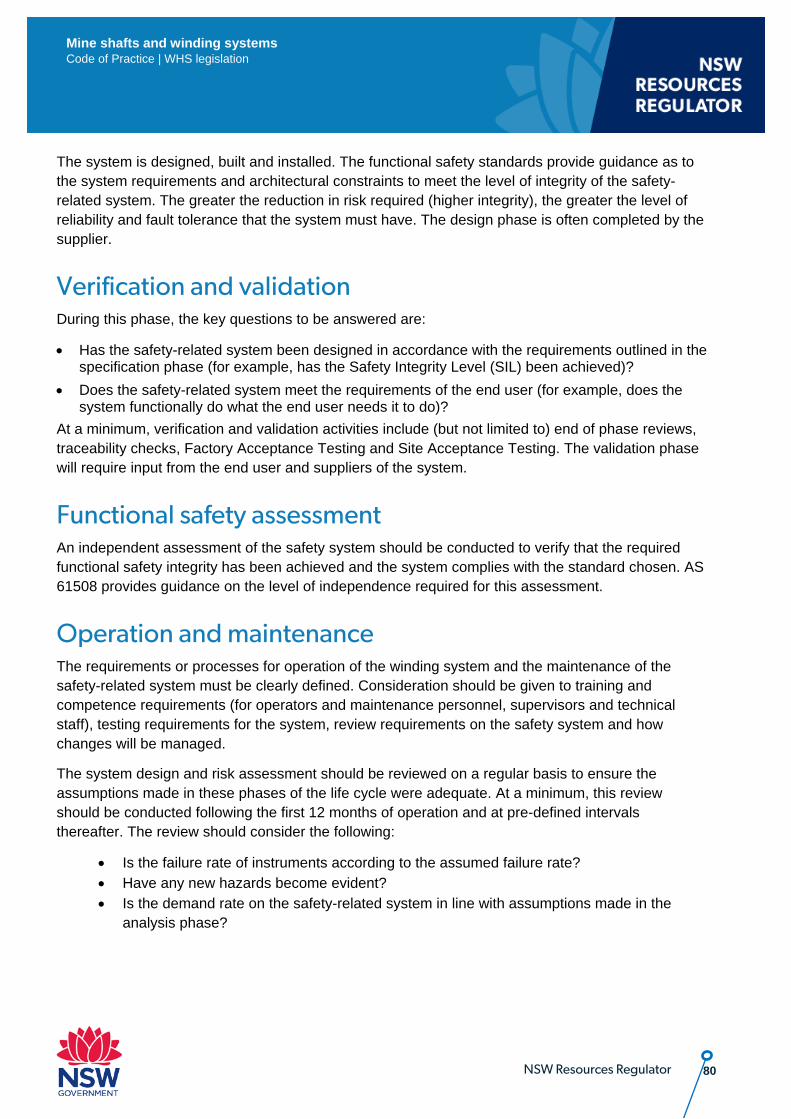
80 NSW Resources Regulator
Mine shafts and winding systems Code of Practice | WHS legislation
The system is designed, built and installed. The functional safety standards provide guidance as to the system requirements and architectural constraints to meet the level of integrity of the safety-related system. The greater the reduction in risk required (higher integrity), the greater the level of reliability and fault tolerance that the system must have. The design phase is often completed by the supplier.
Verification and validation During this phase, the key questions to be answered are:
• Has the safety-related system been designed in accordance with the requirements outlined in the specification phase (for example, has the Safety Integrity Level (SIL) been achieved)?
• Does the safety-related system meet the requirements of the end user (for example, does the system functionally do what the end user needs it to do)?
At a minimum, verification and validation activities include (but not limited to) end of phase reviews, traceability checks, Factory Acceptance Testing and Site Acceptance Testing. The validation phase will require input from the end user and suppliers of the system.
Functional safety assessment An independent assessment of the safety system should be conducted to verify that the required functional safety integrity has been achieved and the system complies with the standard chosen. AS 61508 provides guidance on the level of independence required for this assessment.
Operation and maintenance The requirements or processes for operation of the winding system and the maintenance of the safety-related system must be clearly defined. Consideration should be given to training and competence requirements (for operators and maintenance personnel, supervisors and technical staff), testing requirements for the system, review requirements on the safety system and how changes will be managed.
The system design and risk assessment should be reviewed on a regular basis to ensure the assumptions made in these phases of the life cycle were adequate. At a minimum, this review should be conducted following the first 12 months of operation and at pre-defined intervals thereafter. The review should consider the following:
• Is the failure rate of instruments according to the assumed failure rate? • Have any new hazards become evident? • Is the demand rate on the safety-related system in line with assumptions made in the
analysis phase?
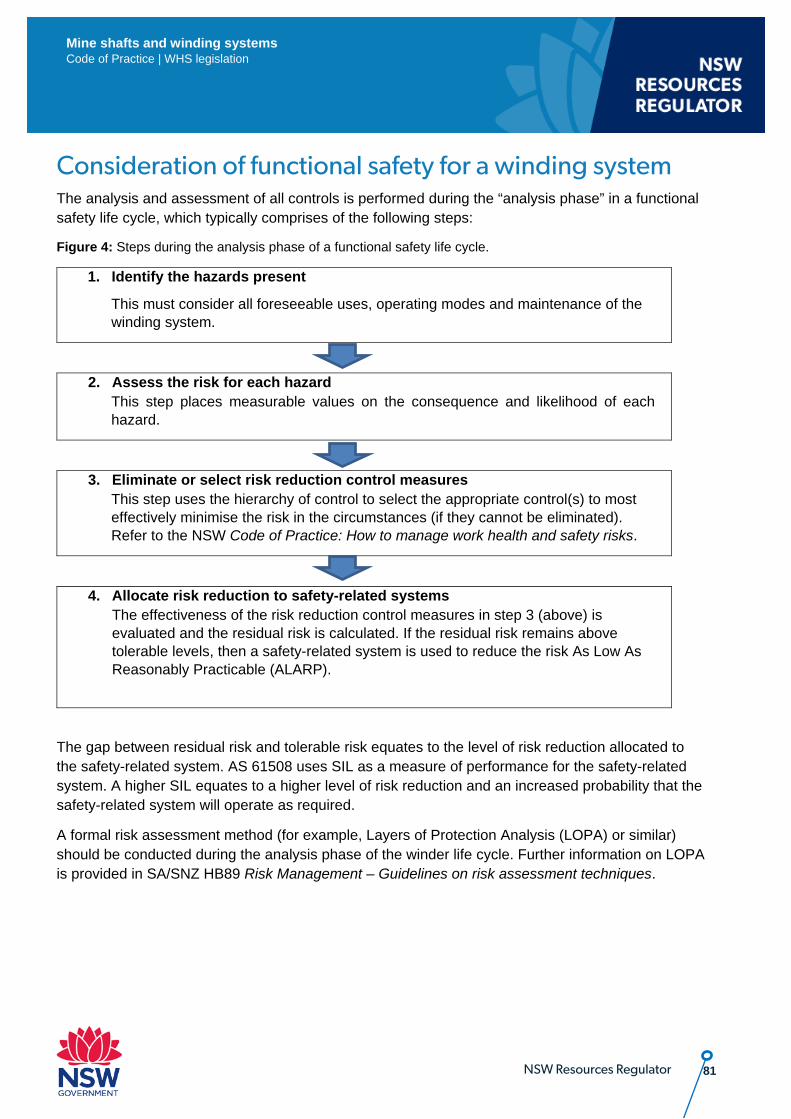
81 NSW Resources Regulator
Mine shafts and winding systems Code of Practice | WHS legislation
Consideration of functional safety for a winding system The analysis and assessment of all controls is performed during the “analysis phase” in a functional safety life cycle, which typically comprises of the following steps:
Figure 4: Steps during the analysis phase of a functional safety life cycle.
1. Identify the hazards present
This must consider all foreseeable uses, operating modes and maintenance of the winding system.
2. Assess the risk for each hazard This step places measurable values on the consequence and likelihood of each hazard.
3. Eliminate or select risk reduction control measures This step uses the hierarchy of control to select the appropriate control(s) to most effectively minimise the risk in the circumstances (if they cannot be eliminated). Refer to the NSW Code of Practice: How to manage work health and safety risks.
4. Allocate risk reduction to safety-related systems The effectiveness of the risk reduction control measures in step 3 (above) is evaluated and the residual risk is calculated. If the residual risk remains above tolerable levels, then a safety-related system is used to reduce the risk As Low As Reasonably Practicable (ALARP).
The gap between residual risk and tolerable risk equates to the level of risk reduction allocated to the safety-related system. AS 61508 uses SIL as a measure of performance for the safety-related system. A higher SIL equates to a higher level of risk reduction and an increased probability that the safety-related system will operate as required.
A formal risk assessment method (for example, Layers of Protection Analysis (LOPA) or similar) should be conducted during the analysis phase of the winder life cycle. Further information on LOPA is provided in SA/SNZ HB89 Risk Management – Guidelines on risk assessment techniques.
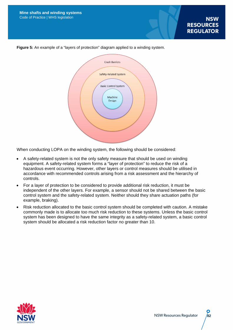
82 NSW Resources Regulator
Mine shafts and winding systems Code of Practice | WHS legislation
Figure 5: An example of a “layers of protection” diagram applied to a winding system.
When conducting LOPA on the winding system, the following should be considered:
• A safety-related system is not the only safety measure that should be used on winding equipment. A safety-related system forms a “layer of protection” to reduce the risk of a hazardous event occurring. However, other layers or control measures should be utilised in accordance with recommended controls arising from a risk assessment and the hierarchy of controls.
• For a layer of protection to be considered to provide additional risk reduction, it must be independent of the other layers. For example, a sensor should not be shared between the basic control system and the safety-related system. Neither should they share actuation paths (for example, braking).
• Risk reduction allocated to the basic control system should be completed with caution. A mistake commonly made is to allocate too much risk reduction to these systems. Unless the basic control system has been designed to have the same integrity as a safety-related system, a basic control system should be allocated a risk reduction factor no greater than 10.
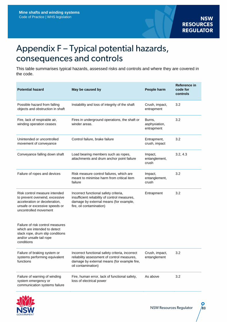
83 NSW Resources Regulator
Mine shafts and winding systems Code of Practice | WHS legislation
Appendix F – Typical potential hazards, consequences and controls This table summarises typical hazards, assessed risks and controls and where they are covered in the code.
Potential hazard May be caused by People harm Reference in code for controls
Possible hazard from falling objects and obstruction in shaft
Instability and loss of integrity of the shaft Crush, impact, entrapment
3.2
Fire, lack of respirable air, winding operation ceases
Fires in underground operations, the shaft or winder areas.
Burns, asphyxiation, entrapment
3.2
Unintended or uncontrolled movement of conveyance
Control failure, brake failure Entrapment, crush, impact
3.2
Conveyance falling down shaft Load bearing members such as ropes, attachments and drum anchor point failure
Impact, entanglement, crush
3.2, 4.3
Failure of ropes and devices
Risk measure control failures, which are meant to minimise harm from critical item failure
Impact, entanglement, crush
3.2
Risk control measure intended to prevent overwind, excessive acceleration or deceleration, unsafe or excessive speeds or uncontrolled movement
Failure of risk control measures which are intended to detect slack rope, drum slip conditions and/or unsafe tail rope conditions
Incorrect functional safety criteria, insufficient reliability of control measures, damage by external means (for example, fire, oil contamination)
Entrapment 3.2
Failure of braking system or systems performing equivalent functions
Incorrect functional safety criteria, incorrect reliability assessment of control measures, damage by external means (for example fire, oil contamination)
Crush, impact, entanglement
3.2
Failure of warning of winding system emergency or communication systems failure
Fire, human error, lack of functional safety, loss of electrical power
As above 3.2
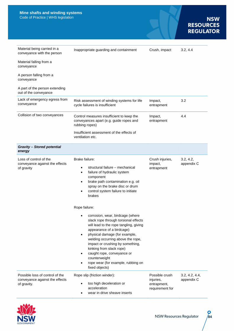
84 NSW Resources Regulator
Mine shafts and winding systems Code of Practice | WHS legislation
Material being carried in a conveyance with the person Material falling from a conveyance A person falling from a conveyance A part of the person extending out of the conveyance
Inappropriate guarding and containment Crush, impact 3.2, 4.4
Lack of emergency egress from conveyance
Risk assessment of winding systems for life cycle failures is insufficient
Impact, entrapment
3.2
Collision of two conveyances Control measures insufficient to keep the conveyances apart (e.g. guide ropes and rubbing ropes)
Insufficient assessment of the effects of ventilation etc.
Impact, entrapment
4.4
Gravity – Stored potential energy
Loss of control of the conveyance against the effects of gravity
Brake failure:
• structural failure – mechanical • failure of hydraulic system
component • brake path contamination e.g. oil
spray on the brake disc or drum • control system failure to initiate
brakes
Rope failure:
• corrosion, wear, birdcage (where slack rope through torsional effects will lead to the rope tangling, giving appearance of a birdcage)
• physical damage (for example, welding occurring above the rope, impact or crushing by something, kinking from slack rope)
• caught rope, conveyance or counterweight
• rope wear (for example, rubbing on fixed objects)
Crush injuries, impact, entrapment
3.2, 4.2, appendix C
Possible loss of control of the conveyance against the effects of gravity.
Rope slip (friction winder):
• too high deceleration or acceleration
• wear in drive sheave inserts
Possible crush injuries, entrapment, requirement for
3.2, 4.2, 4.4, appendix C
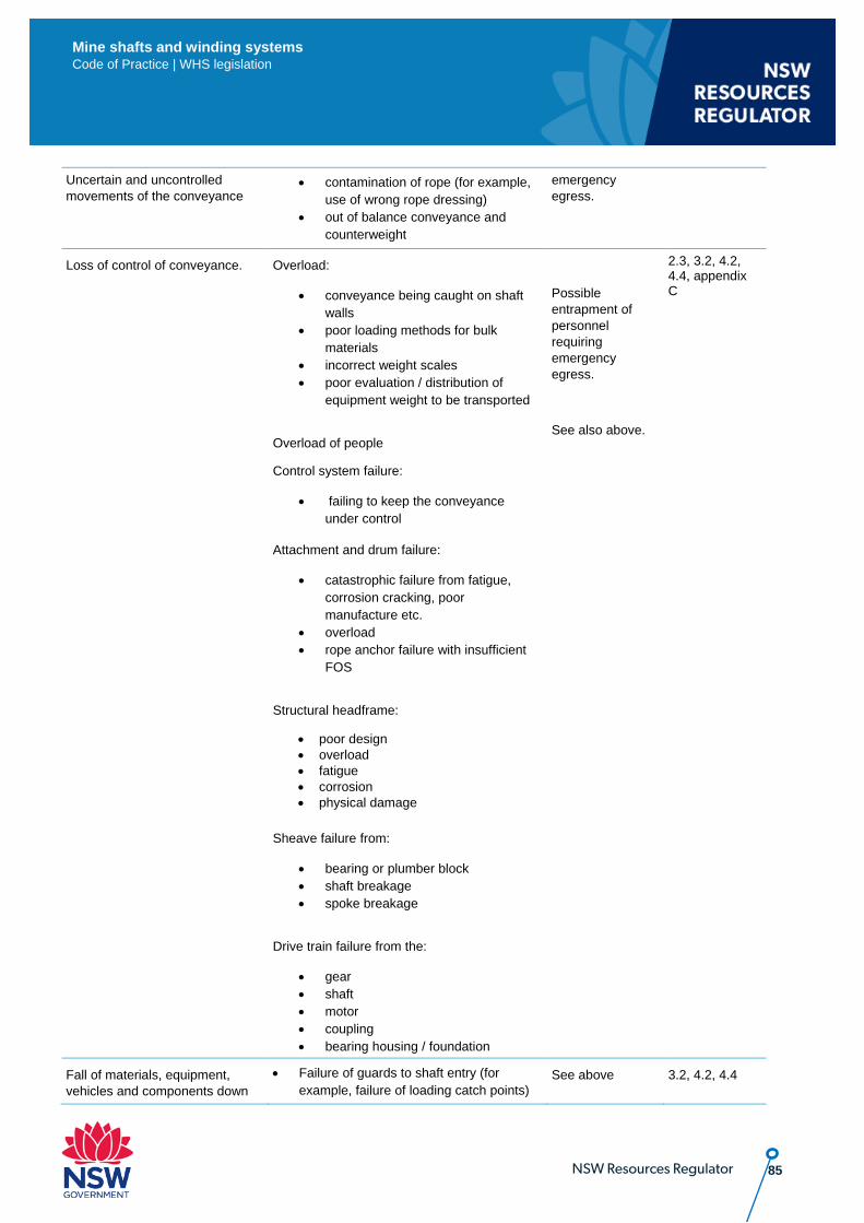
85 NSW Resources Regulator
Mine shafts and winding systems Code of Practice | WHS legislation
Uncertain and uncontrolled movements of the conveyance
• contamination of rope (for example, use of wrong rope dressing)
• out of balance conveyance and counterweight
emergency egress.
Loss of control of conveyance.
Overload:
• conveyance being caught on shaft walls
• poor loading methods for bulk materials
• incorrect weight scales • poor evaluation / distribution of
equipment weight to be transported
Overload of people
Control system failure:
• failing to keep the conveyance under control
Attachment and drum failure:
• catastrophic failure from fatigue, corrosion cracking, poor manufacture etc.
• overload • rope anchor failure with insufficient
FOS
Structural headframe:
• poor design • overload • fatigue • corrosion • physical damage
Sheave failure from:
• bearing or plumber block • shaft breakage • spoke breakage
Drive train failure from the:
• gear • shaft • motor • coupling • bearing housing / foundation
Possible entrapment of personnel requiring emergency egress.
See also above.
2.3, 3.2, 4.2, 4.4, appendix C
Fall of materials, equipment, vehicles and components down
• Failure of guards to shaft entry (for example, failure of loading catch points)
See above 3.2, 4.2, 4.4
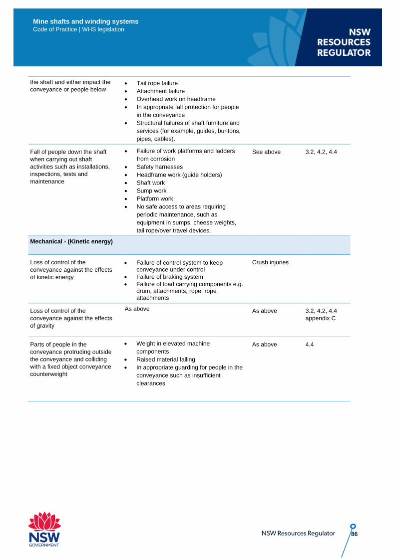
86 NSW Resources Regulator
Mine shafts and winding systems Code of Practice | WHS legislation
the shaft and either impact the conveyance or people below
• Tail rope failure • Attachment failure • Overhead work on headframe • In appropriate fall protection for people
in the conveyance • Structural failures of shaft furniture and
services (for example, guides, buntons, pipes, cables).
Fall of people down the shaft when carrying out shaft activities such as installations, inspections, tests and maintenance
• Failure of work platforms and ladders from corrosion
• Safety harnesses • Headframe work (guide holders) • Shaft work • Sump work • Platform work • No safe access to areas requiring
periodic maintenance, such as equipment in sumps, cheese weights, tail rope/over travel devices.
See above 3.2, 4.2, 4.4
Mechanical - (Kinetic energy)
Loss of control of the conveyance against the effects of kinetic energy
• Failure of control system to keep conveyance under control
• Failure of braking system • Failure of load carrying components e.g.
drum, attachments, rope, rope attachments
Crush injuries
Loss of control of the conveyance against the effects of gravity
As above As above 3.2, 4.2, 4.4 appendix C
Parts of people in the conveyance protruding outside the conveyance and colliding with a fixed object conveyance counterweight
• Weight in elevated machine components
• Raised material falling • In appropriate guarding for people in the
conveyance such as insufficient clearances
As above 4.4

87 NSW Resources Regulator
Mine shafts and winding systems Code of Practice | WHS legislation
Appendix G – Sample fault tree analysis Fault tree analysis may be used for:
• identifying the possible relationships which will result in the top event (in this case failure of brake function).
• obtaining a thorough understanding of the logic and basic causes leading to the top event and recording this analysis
• a qualitative and quantitative evaluation of the top event, to then possibly model system failures in risk analysis.
Scenario: The fault tree analysis below represents the use of this method to investigate factors causing a possible failure of a brake function. A brake function is used to slow and/or stop a winding system. In this scenario, a brake is called on to apply in a winder system and it fails to carry out its function. This failure is represented by the top event in the fault tree analysis.
Figure 6: Depicts a hypothetical shaft sinking winder system as a block diagram.
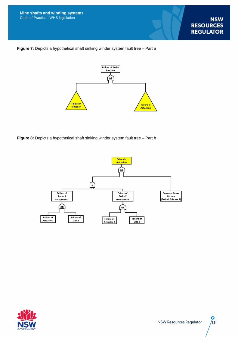
88 NSW Resources Regulator
Mine shafts and winding systems Code of Practice | WHS legislation
Figure 7: Depicts a hypothetical shaft sinking winder system fault tree – Part a
Figure 8: Depicts a hypothetical shaft sinking winder system fault tree – Part b
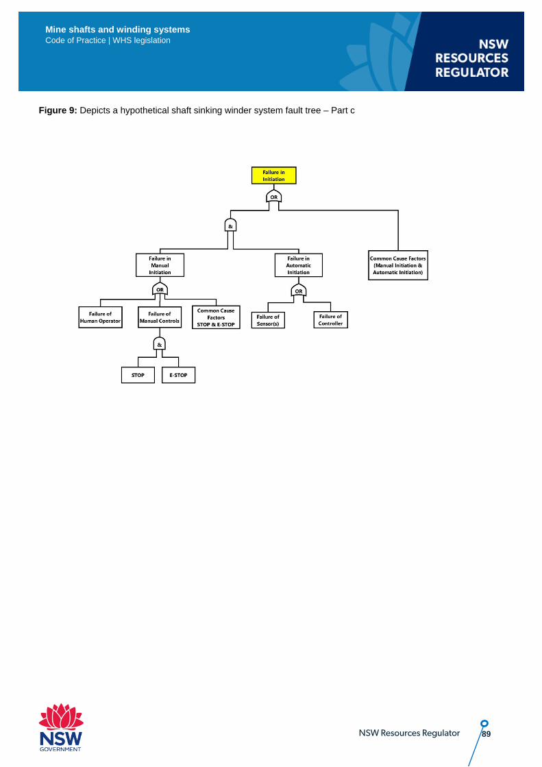
89 NSW Resources Regulator
Mine shafts and winding systems Code of Practice | WHS legislation
Figure 9: Depicts a hypothetical shaft sinking winder system fault tree – Part c