Design of Powered Winding Systems: A Functional Safety Approach · EES008-4 Design of powered...
81
TECHNICAL REFERENCE EES008-4 Electrical Engineering Safety Design of powered winding systems A Functional Safety Approach Produced by Mine Safety Operations Branch Industry and Investment NSW March 2011
Transcript of Design of Powered Winding Systems: A Functional Safety Approach · EES008-4 Design of powered...

T E C H N I C A L R E F E R E N C E
EES008-4 Electrical Engineering Safety
Design of powered winding systems A Functional Safety Approach
Produced by Mine Safety Operations Branch Industry and Investment NSW March 2011
Public comment period Please note that this technical reference is published in draft form for the purpose of obtaining public comment.
Your feedback is welcomed and will assist with reviewing and improving the document. A feedback form is provided in the appendices for your convenience.
The closing date for public comment is Friday 20 May 2011.
EES008-4 Design of powered winding systems – a functional safety approach March 2011
Page 2 of 81
D I S C L A I M E R The compilation of information contained in this document relies upon material and data derived from a number of third party sources and is intended as a guide only in devising risk and safety management systems for the working of mines and is not designed to replace or be used instead of an appropriately designed safety management plan for each individual mine. Users should rely on their own advice, skills and experience in applying risk and safety management systems in individual workplaces.
Use of this document does not relieve the user (or a person on whose behalf it is used) of any obligation or duty that might arise under any legislation (including the Occupational Health and Safety Act 2000, any other act containing requirements relating to mine safety and any regulations and rules under those acts) covering the activities to which this document has been or is to be applied.
The information in this document is provided voluntarily and for information purposes only. The New South Wales Government does not guarantee that the information is complete, current or correct and accepts no responsibility for unsuitable or inaccurate material that may be encountered.
Unless otherwise stated, the authorised version of all reports, guides, data and other information should be sourced from official printed versions of the agency directly. Neither Industry & Investment NSW, the New South Wales Government, nor any employee or agent of the Department, nor any author of or contributor to this document produced by the Department, shall be responsible or liable for any loss, damage, personal injury or death howsoever caused. A reference in this document to "the Department" or "Industry and Investment NSW" or "I&I NSW" is taken to be a reference to the Department of Industry and Investment.
Users should always verify historical material by making and relying upon their own separate enquiries prior to making any important decisions or taking any action on the basis of this information.
This publication contains information regarding occupational health, safety, injury management or workers compensation. It includes some of your obligations under the various workers compensation and occupational health and safety legislation that Industry & Investment NSW administers. To ensure you comply with your legal obligations you must refer to the appropriate legislation.
In the event of inconsistency with a provision of any relevant Act or Regulation the provision prevails over the guideline.
This publication may refer to NSW legislation that has been amended or repealed. When reading this publication you should always refer to the latest laws. Information on the latest laws can be checked at: www.legislation.nsw.gov.au Alternatively, phone (02) 4931 6666.
EES008-4 Design of powered winding systems – a functional safety approach March 2011
Page 3 of 81

Foreword Industry and Investment NSW (I&I NSW) has a vision for electrical engineering safety, which is:
“A mining and extractive industry that has eliminated death and injuries from electrically powered and electrically controlled equipment.”
Electrical engineering safety encompasses: • Prevention of electric shock and burns, (electrocution, death or injury as a result
of a shock, radiation burns, flash burns, burning particles and plasma) • Prevention of electrical arcing and surface temperatures that have sufficient
energy to ignite gas and/or dust • Prevention of fires caused by the malfunction of electrical equipment • Prevention of injury and death from unintended operation, failure to stop or
failure to operate, of electrically powered and electrically controlled equipment • Use of electrical technology to provide safe-guards and monitoring for non-
electrical hazards and electrical hazards with a safety integrity level appropriate for the risk.
Supporting this vision is a philosophy of operation outlined in the Strategic and Operational Plan for Electrical and Engineering Safety in NSW Mines, which can be viewed at www.dpi.nsw.gov.au. The philosophy of operation embraces a System Safety Approach, applying the Hierarchy of Risk Controls and the Risk Reduction Precedence, and fostering a Positive Safety Culture. Satisfactory electrical engineering safety has to be achieved in the context of the mining industry’s increasing electricity consumption and its use of electrical technology, with resulting increases in size (power rating) and complexity. With this comes a changing risk profile. To adequately manage the safety risks posed by electrical equipment and technology the hazards, risks and risk controls need to be thoroughly understood. This understanding must be at an engineering level, so electrical engineers within the management structure of coal or mining operations will be responsible for development, periodic review and day to day implementation of the Electrical Engineering Safety aspects of a powered winding system.
This document is one of a series dealing with powered winding systems. These documents are consistent with the above philosophy of operation and are a key element in realising the vision and points 4 and 5 for electrical engineering safety listed above.
The documents in the series are: EES008.1 Design of Powered Winding Systems - Electrical Engineering Safety – General Requirements & Registration EES008.2 Design of Powered Winding Systems - Electrical Engineering Safety – Definitions and types of winders EES008.3 Design of Powered Winding Systems - Electrical Engineering Safety – a prescriptive approach EES008.4 Design of Powered Winding Systems - Electrical Engineering Safety – a Functional Safety approach EES008.5 Life-Cycle Management of Powered Winding Systems - Electrical Engineering Safety Requirements
EES008-4 Design of powered winding systems – a functional safety approach March 2011
Page 4 of 81

Current legislation is consistent with this philosophy. In particular Clauses 107 and 113 of the Occupational Health and Safety Regulation 2001 recognise the high risk nature of mine winders, so legislation requires that the Director General design register and item register powered winding systems.
The purpose of this document is to facilitate, within an electrical engineering safety context, the design registration of powered winding systems and to assist coal and mine operators to maintain powered winding systems in a safe state.
Use of this document will:
• Enhance the management of safety risks associated with powered winding systems through good and safe electrical engineering practice
• Contribute significantly toward the prevention of unintended operation of mine winders and preventing any unintended operation from injuring personnel.
Use this technical reference to assess your Powered Winding Systems.
Use this technical reference as an aid to the design of Powered Winding Systems.
This technical reference will be used by Mine Safety Operations to assess powered winding systems for design registration purposes and routine assessment activities.
John Francis Waudby Senior Inspector of Electrical Engineering – Special Projects
EES008-4 Design of powered winding systems – a functional safety approach March 2011
Page 5 of 81

Table of Contents Foreword................................................................................................................................. 4
Table of Contents.................................................................................................................... 6
1. Establishment ..................................................................................................................... 8
1.1 Title................................................................................................................................ 8
1.2 Purpose ......................................................................................................................... 8
1.3 Scope ............................................................................................................................ 8
1.4 Authority ........................................................................................................................ 9
1.5 Definitions...................................................................................................................... 9
1.6 Applicable legislation..................................................................................................... 9
1.7 Referenced Gazette Notices ......................................................................................... 9
1.8 Referenced Standards and Guidelines ......................................................................... 9
1.9 Acronyms ...................................................................................................................... 9
1.10 Who is affected by this Technical Reference? ............................................................ 9
2. Powered winding system safety related circuits ............................................................... 10
2.1 Functional safety approach ......................................................................................... 10
2.2 Explanation of the Functional Safety Approach .......................................................... 11
2.3 Risk reduction.............................................................................................................. 13
2.4 Functional Safety Standards ....................................................................................... 17
3. Worked Example of the Functional Safety Approach as applied to a Powered Winding System.................................................................................................................................. 28
3.1 AS61508 Step 1 - Concept.......................................................................................... 28
3.2 AS61508 Step 2 – Overall Scope Definition................................................................ 33
3.3 AS61508 Step 3 – Hazard and Risk Analysis ............................................................. 38
AS61508 Step 4 – Overall Safety Requirements .............................................................. 41
AS62061 Step 1 – Identification of SRCFs ....................................................................... 45
AS62061 Step 2 – Initial Concept ..................................................................................... 47
AS62061 Step 3 – Detailed Safety Requirements of Functional Blocks ........................... 48
AS62061 Step 4 – Allocate Function Blocks to SRECS Sub-systems.............................. 53
AS62061 Step 5 - Verification ........................................................................................... 58
AS62061 Step 6 – Design and Develop Sub-systems ...................................................... 59
AS62061 Step 7 – Design and Develop Diagnostics ........................................................ 63
AS62061 Step 8 – Determine the Achieved SIL for each SRCF....................................... 65
AS62061 Step 9 – Document the SRECS Architecture .................................................... 68
AS62061 Step 10 – Implement the Designed SRECS...................................................... 69
EES008-4 Design of powered winding systems – a functional safety approach March 2011
Page 6 of 81
AS61508 Step 13 – Overall Safety Validation................................................................... 70
AS61508 Step 14 – Operation and Maintenance.............................................................. 72
AS61508 Step 15 – Modification and Retrofit ................................................................... 77
AS61508 Step 16 – Decommissioning and Disposal ........................................................ 78
4. Appendices ....................................................................................................................... 80
Feedback Sheet ................................................................................................................ 80
I&I NSW Contact details.................................................................................................... 81
EES008-4 Design of powered winding systems – a functional safety approach March 2011
Page 7 of 81

1. Establ ishment
1 . 1 T i t l e
This is the Mining Industry Technical reference – Electrical Technical Reference for Design of Powered Winding Systems Electrical Engineering Safety – a Functional Safety Approach.
1 . 2 P u r p o s e
This document is intended to assist designers and manufactures of powered winding systems, including shaft sinking winders, by indicating parameters which will be considered in the assessment for design registration. It will also aid operators (coal and mine) to obtaining item registration. It also provides specific information on the content of any submission for design registration. Full details of how to obtain design registration is given in Guidance Note GNC-005 NSW DPI Guidance Note – Registration of Plant Designs.
Note: Registration does not limit the responsibility of the designer, manufacturer and operator to ensure that the powered winding system is safe to operate.
This technical reference describes acceptable arrangements that can be tailored to suit the particular needs of an operation. It identifies some control measures relevant to electrical circuitry. It is intended to protect the safety of workers, others in the workplace and property.
This document will facilitate, within an electrical engineering safety context, the registration of powered winding systems and assist mine operators to maintain powered winding systems in a safe state.
The use of this document will:
• enhance the management of safety risks associated with powered winding systems through good and safe electrical engineering practice
• contribute significantly toward the prevention of unintended operation of mine winders and preventing any unintended operation from injuring personnel.
1 . 3 S c o p e
This technical reference extends to all underground operations in NSW that use a powered winding system. This technical reference is intended to provide guidance for any person designing, implementing, managing or reviewing a powered winding system installation.
EES008-4 Design of powered winding systems – a functional safety approach March 2011
Page 8 of 81
1 . 4 A u t h o r i t y
This is an Electrical Engineering Safety Technical Reference and is recommended by the Department of Industry and Investment.
1 . 5 D e f i n i t i o n s
Refer to EES008-2 Design of Powered Winding Systems Electrical Engineering Safety – Definitions and Winder Types.
1 . 6 A p p l i c a b l e l e g i s l a t i o n
Occupational Health and Safety Act 2000 Occupational Health and Safety Regulation 2001 Coal Mine Health and Safety Act 2002 Coal Mine Health and Safety Regulation 2006 Mine Health and Safety Act 2004 Mine Health and Safety Regulation 2007
1 . 7 R e f e r e n c e d G a z e t t e N o t i c e s
Gazette Notice for Powered Winding systems
1 . 8 R e f e r e n c e d S t a n d a r d s a n d G u i d e l i n e s
AS 4024.1 Series - Safety of machinery
AS61508 Series – Functional safety of electrical / electronic / programmable electronic safety-related systems
AS 62061 Safety of machinery - Functional safety of safety-related electrical, electronic and programmable electronic control systems
EES008 – 2 Design of Powered Winding Systems – Electrical Engineering Safety – definitions and types of winders
Guidance Note GNC-005 NSW DPI Guidance Note – Registration of Plant Designs.
1 . 9 A c r o n ym s
AS: Australian Standard
AS/NZS: Australian New Zealand Standard FMECA: Failure Modes and Criticality Analysis OH&S: Occupational Health and Safety
1 . 1 0 W h o i s a f f e c t e d b y t h i s T e c h n i c a l R e f e r e n c e ?
This Technical Reference is relevant for all operators of coal operations in New South Wales where there is a powered winding system.
EES008-4 Design of powered winding systems – a functional safety approach March 2011
Page 9 of 81
2. Powered winding system safety related c ircuits
With regard to Powered Winding Systems the operation’s electrical
engineering arrangements have the following objectives:
• To prevent unintended operation of plant. • To provide electrical safeguards for electrical and non-electrical
hazards with an appropriate safety integrity level. • To generally provide the means by which the safety of electrical plant
is managed including requirements of the applicable legislation. There are two approaches to achieving the above objectives and addressing electrical engineering safety aspects of powered winding systems. These are:
• The functional safety approach • The prescriptive compliance approach.
2 . 1 F u n c t i o n a l s a f e t y a p p r o a c h
Relevant standards
This approach requires that, as appropriate, AS61508, AS61511 or AS62061 is followed.
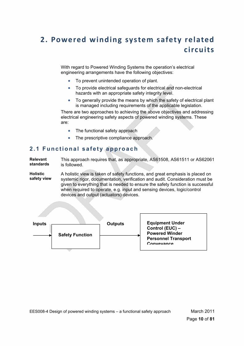
Holistic safety view
A holistic view is taken of safety functions, and great emphasis is placed on systemic rigor, documentation, verification and audit. Consideration must be given to everything that is needed to ensure the safety function is successful when required to operate, e.g. input and sensing devices, logic/control devices and output (actuators) devices.
Outputs
Safety Function
Equipment Under Control (EUC) – Powered Winder Personnel Transport Conveyance
Inputs
EES008-4 Design of powered winding systems – a functional safety approach March 2011
Page 10 of 81
A risk based approach
The approach is risk-based (consistent with AS/NZS4360 and MDG1010) and determines safety integrity requirements for risk controls; that is, it uses safety integrity levels (SILs) to specify reliability and fail-safe performance of safety functions. The SIL is a measure of risk reduction. Determining the amount of risk reduction requires that the uncontrolled risk from the EUC is determined and then compared against the tolerable risk level. The tolerable risk level must specified by the coal operator.
Specifying tolerable risk requires calibration of the corporate safety risk matrix, particularly the likelihood. If the reduction of one level of likelihood equates to an order of magnitude reduction in risk, then effectively, a reduction in one level of likelihood implies an increase in the SIL of 1.
For example: with a risk matrix that has likelihood levels of Likely, Moderate, Unlikely, Rare and Very Rare, to reduce the likelihood from Likely to Rare equates to a risk reduction factor (RRF) of 3 orders of magnitude = 1000 = SIL3.
Achieving risk reduction
When the degree of risk reduction has been determined the amount of risk reduction to each risk control must be allocated. The risk controls in combination must achieve the required risk reduction. For a risk reduction factor of 1000 we can have one risk control with a RRF of 1000, or two risk controls (arranged to give probability multiplication), one with a RRF of 10 and another risk control with an RRF of 100 or any other combination that gives a total RRF of 1000.
Safety Requirements Specification
This risk analysis leads to the development of a Safety Requirements Specification for the powered winding system. This specification shall provide for a level of risk that is less than or equal to that provided for by the prescriptive compliance approach.
Note:
For very simple winding systems the AS4024 approach may be used to determine the relevant category (CAT) and then relate that CAT to a SIL by using AS62061. If within the design a programmable system (PES) is used then it will need to conform to AS61508.
2 . 2 E x p l a n a t i o n o f t h e F u n c t i o n a l S a f e t y A p p r o a c h
2 .2 .1 Standard Def in i t ion o f Funct iona l Safe ty
Functional safety is defined in AS61508 as: That part of the overall safety of the Equipment Under Control (ie. the EUC and the EUC control system) which depends on the correct functioning of the Electrical / Electronic / Programmable Electronic (E/E/PE) safety-related systems, other technology safety-related systems and external risk reduction facilities.
EES008-4 Design of powered winding systems – a functional safety approach March 2011
Page 11 of 81
The following notes explain the philosophy and concepts embodied by this
definition and the approach taken within the various standards governing the implementation of the ‘functional safety’ approach.
2 .2 .2 Br ie f H is tory o f the Funct iona l Safe ty Approach Use of Programmable Electronic Systems (PES)
Since the 1980s there has been an increasing use of Programmable Electronic Systems in safety applications (PES). Traditionally, safety functions were accomplished by hard-wired systems that had well understood failure modes and rates. The use of electronics and software to perform safety functions has provided benefits such as flexibility, increased functionality and ease of use however the predictability of failure has been compromised. Industries recognised that it can be very difficult to demonstrate the reliability and fail-safe nature of complex software and micro-electronic hardware.
Increasing security concerns – the HSE response
Increasing use of PES gave rise to increasing concerns about the security of these systems. The Health and Safety Executive (HSE) in the UK was at the forefront of these concerns and funded research into the safety integrity of computer systems.
In 1987 the HSE issued the Guidelines for use of PES for Safety Related Applications. These guidelines highlighted the need for high levels of safety at every stage of design, installation and operation of PES. The safety lifecycle concept was formalised whereby safety was not restricted to any particular phase of a system’s design process but spanned the whole design process and continued into commissioning, operation/maintenance etc.
German standards
Similarly, in Germany, the DIN standards committee developed DIN V19250, the first edition being released in 1989. This standard introduced the concept of the qualitative ‘risk graph’ to select one of 8 levels of safety integrity – called the ‘AK’ class. DIN V19250 and DIN VDE 0801 are still used today by TÜV Industrie Service GmbH to certify PES.
The US standard
In the USA ISA developed and released the ANSI/ISA S84 standard in 1996. The concept of Safety Integrity Levels (SILs) was firmly established in this standard.
IEC standards In parallel, but taking somewhat longer, an IEC committee produced the first draft of IEC1508 in 1994. Finally, the 7 part IEC61508 standard was approved between 1998 and 2000. SILs reached the international arena with the approval of this generic standard for functional safety. The 7 parts of IEC61508 were adopted by Australia as AS61508 during 1999 to 2001.
More recently, the IEC61508 standard has been augmented by industry-specific standards for functional safety, namely:
• IEC61511 (in 3 parts): Functional Safety – Safety Instrumented Systems for the Process Industry.
• IEC62061 (in 1 part): Safety of Machinery – Functional Safety of safety-related electrical, electronic and programmable electronic control systems.
EES008-4 Design of powered winding systems – a functional safety approach March 2011
Page 12 of 81
Australian adoption
IEC61511 was adopted by Australia as AS61511 in 2004, and IEC62061 was adopted as AS62061 in 2006.
Extended scope of PES
Importantly, these standards have extended the original scope of PES to include any electrical based system performing a safety function. Terms commonly used to describe such systems are:
• Electrical/Electronic/Programmable Electronic System (E/E/PES). • Safety-related System (SRS). • Safety Instrumented System (SIS). • Safety Instrumented Function (SIF). • Instrumented Protective Function (IPF). • Safety Related Electrical Control System (SRECS).
Summary In summary, all of these standards are primarily concerned with the use of electrical / electronic / PES systems that perform safety functions and, acknowledging that no system is perfect, ensuring that an appropriate level of integrity is built into the system.
2 . 3 R i s k r e d u c t i o n
A natural survival mechanism
The Functional Safety approach is focused on risk reduction.
Risk reduction usually occurs naturally or sub-consciously as people go about their everyday lives. We put shoes on to protect our feet, look before crossing the road, clean our teeth, drive on the correct side of the road, etc. In industry risk reduction is more formalised. This is because the consequences and/or likelihood of something going wrong are usually much greater – i.e. the risk is greater.
Risk reduction by design
During the design process for example, standards and good industry practices are adhered to so that mistakes made in the past that have resulted in unwanted events are not repeated. Furthermore, safety legislation in Australia and many other places requires a risk assessment process be an inherent part of the design process.
A risk model Figure 1 shows the general risk model from AS/IEC61508 Part 5. It is used to illustrate the general principles of risk reduction and safety integrity concepts.
EES008-4 Design of powered winding systems – a functional safety approach March 2011
Page 13 of 81

Figure 1 – General Risk Model
Model assumptions
This general model assumes that:
• there is an Equipment Under Control (EUC), ie. a machine • there is a Machine Control System (MCS) • there are associated human factor issues • the safety protective features comprise:
o external risk reduction facilities
o E/E/PE Safety Related Control Functions (SRCFs)
o other technology safety related systems.
Importantly, the AS61508 standard requires that:
“The risk model for a specific application will need to be developed taking into account the specific manner in which the necessary risk reduction is actually being achieved by the E/E/PE safety systems and/or other technology safety-related systems and/or external risk reduction facilities.”
Allocation of SILs
Allocation of Safety Integrity Levels (SILs) is performed by means of defining the necessary risk reduction and apportioning it to one or more risk reduction measures.
Layers of Protection are a way of presenting multiple independent layers of safety so that a SIL may be allocated.
Figure 2 illustrates the typical way of presenting the layers of protection for a typical industrial machine.
EES008-4 Design of powered winding systems – a functional safety approach March 2011
Page 14 of 81

EES008-4 Design of powered winding systems – a functional safety approach March 2011
Page 15 of 81
Figure 2 – Layers of Protection Model
2 .3 .1 Safe ty in tegr i t y leve ls Safety Integrity Levels are used to define the necessary risk reduction
required of an E/E/PES Safety Related Control Function (SRCF).
AS/IEC61508 defines a SIL as: “A discrete level (one out of a possible four) for specifying the safety integrity requirements for the safety functions to be allocated to the E/E/PE safety-related systems, where Safety Integrity Level 4 has the highest level of safety integrity and Safety Integrity Level 1 has the lowest”.
It should be noted that the AS/IEC62061 does not cover the requirements for SIL4 Safety Related Control Functions (SRCFs).

High Demand / Continuous Mode
For industrial machinery it is typically expected that many SRCFs will be ‘demanded’ often. Generally, where demands on the SRCF occur more frequently than once per year, or more frequently than twice the frequency of functional testing, then ‘high demand’ or ‘continuous mode’ is applicable. ‘High demand’ mode can also apply inadvertently as a result of poorly tuned or defective machine controls. These may place additional demands on a ‘low demand’ SRCF and effectively place it into ‘high demand’ mode.
It is also possible for a SRCF to be operating in ‘continuous’ mode in a machinery application. Perhaps the most obvious example of a SRCF operating in this mode are machinery safeguards such as a light curtain interlock to prevent limbs being caught in moving parts of a machine in a production line.
A good measure of whether a SRCF is operating in ‘continuous’ mode is that when the SRCF itself experiences a failure then the unwanted event it was designed to prevent also occurs, either immediately, or very shortly afterwards.
Figure 3 shows the SIL targets for ‘high demand’ or ‘continuous’ mode safety functions.
Figure 3 – High demand safety targets
HIGH DEMAND & CONTINUOUS MODE OF OPERATION (more than one demand on the safety function per year or
continuous demand)
SIL Target Probability of a Dangerous Failure (per hour) (PFH)
4 PFH < 10-8
3 10-8 ≤ PFH < 10-7
2 10-7 ≤ PFH < 10-6
1 10-6 ≤ PFH < 10-5
Low Demand Mode
Alternatively, if an SRCF is demanded less than once per year and less frequently than twice the frequency of functional testing, then ‘low demand’ is applicable.
Figure 4 shows the SIL targets for ‘low demand’ mode safety functions.
EES008-4 Design of powered winding systems – a functional safety approach March 2011
Page 16 of 81

Figure 4 – Low demand safety targets
LOW DEMAND MODE OF OPERATION (less than one demand on the safety function per year)
SIL Target Probability of Failure on Demand (PFD)
Target Risk Reduction Factor (RRF)
(*Note)
4 PFD < 10-4 RRF > 10,000
3 10-4 ≤ PFD < 10-3 10,000 ≥ RRF > 1,000
2 10-3 ≤ PFD < 10-2 1,000 ≥ RRF > 100
1 10-2 ≤ PFD < 10-1 100 ≥ RRF > 10
Note: RRF = 1/PFD
2 . 4 F u n c t i o n a l S a f e t y S t a n d a r d s
AS61508 The IEC61508 standard was adopted by Standards Australia as AS61508 during 1999 and 2001. It sets out a generic approach for all safety lifecycle activities for systems comprised of electrical and/or electronic and/or programmable electronic systems. The seven parts to the standard are as follows:
Part 1 – Development of the overall safety requirements.
Part 2 – Realisation phase for Safety System hardware.
Part 3 – Realisation phase for Safety System software.
Part 4 – Definitions and abbreviations.
Part 5 – Risk based approaches to the development of SIL requirements.
Part 6 – Guidelines for Parts 2 & 3.
Part 7 – Overview of techniques and measures.
Each part is described in more detail below.
Part 1 This part provides the overall framework for the achievement of functional safety. It covers the technical requirements for:
• Development of the overall safety requirements (concept, scope, definition, hazard and risk analysis) – clause 7.1 to 7.5.
• Allocation of the safety requirements to the safety related systems – clause 7.6.
EES008-4 Design of powered winding systems – a functional safety approach March 2011
Page 17 of 81
• Installation and commissioning and safety validation of the safety
related systems – clause 7.13 to 7.14. • Operation and maintenance, modification and retrofit,
decommissioning or disposal of safety related systems – clause 7.15 to 7.17.
• Documentation of the Safety System lifecycle – clause 5 and Annex A.
• Management of functional safety for the Safety System lifecycle – clause 6.
• Functional safety assessment during the Safety System lifecycle – clause 8.
Part 2 This part covers the realisation phase for the safety related hardware – i.e. it:
• Specifies how to refine the information developed in accordance with Part 1, and specifies how the overall safety requirements are refined into the hardware safety function requirements and safety integrity requirements.
• Specifies requirements for activities that are to be applied during the design and manufacture of the Safety System hardware (i.e. establishes the hardware safety lifecycle model).
• Specifies the information necessary for carrying out the installation, commissioning and final safety validation of the Safety System hardware (but does not address operation and maintenance – see part 1- only the requirements for the preparation of information and procedures needed by the end user for operation and maintenance).
• Specifies the requirements to be met by the organisation carrying out any modifications of the safety related system - clause 7.8.2.
• Covers systematic error avoidance techniques – Annex B.
Part 3 This part covers the realisation phase for the safety related system software – i.e. it:
• Requires that the software safety functions and software integrity levels be specified.
• Establishes requirements for safety lifecycle phases and activities, which shall be applied during the design and development of the safety related software (the software safety lifecycle model).
• Provides requirements for information relating to the software validation to be passed to the organisation carrying out the Safety System integration.
• Provides requirements for the preparation of information and procedures concerning software needed by the user for the operation and maintenance of the Safety System.
• Provides requirements to be met by the organisation carrying out modifications to safety related software. – clause 7.8.2.
Part 4 This part covers definitions and abbreviations used in the other parts.
EES008-4 Design of powered winding systems – a functional safety approach March 2011
Page 18 of 81
Part 5 This part covers risk-based approaches to the development of the safety
integrity requirements. It covers:
• The underlying concepts of risk and the relationship of risk to safety integrity.
• A number of methods that enable SILs to be determined.
Part 6 This part contains guidelines for the application of Parts 2 and 3. It includes:
• A brief overview of the requirements of Parts 2 & 3 and sets out the functional steps in their application.
• An example technique (simplified equations) for calculating the probabilities of hardware failure – for both low and high demand modes.
• A worked example of calculating diagnostic coverage. • A methodology for quantifying the effect of hardware related common
cause failures on the probability of failure. • Worked examples of the application of the software safety integrity
tables specified in Part 3.
Part 7 This part presents an overview of safety techniques and measures relevant to Parts 2 and 3. For example:
• Hardware techniques such as monitoring of relay contacts, majority voting, de-energise to trip, separation of electrical and information cabling, etc.
• Systematic failure avoidance techniques such as project management, traceable documentation, skilled operators etc.
• Software techniques such as data flow diagrams, temporal logic, defensive programming, on line checking, certified tools, error seeding, Fagan inspections, process simulation etc.
AS62061 This standard is machine sector specific and is within the functional safety framework of IEC 61508. It was released in 2003 and adopted as AS62061 in 2006.
This standard is intended for use by machinery designers, control system manufacturers and integrators, and others involved in the specification, design and validation of Safety-related Electrical Control Systems (SRECS). It is intended to facilitate the specification of the performance of SRECS in relation to the significant hazards associated with machines.
It also sets out an approach and provides requirements to achieve the necessary performance. Measures are given to co-ordinate the performance of the SRECS with the intended risk reduction taking into account the probabilities and consequences of random or systematic faults within the electrical control system. A suggested methodology for Safety Integrity Level (SIL) assignment is also given and simplified calculations are provided for the determination of the achieved SIL.
Reference is made to AS/IEC61508 through-out the standard. There is only one part to this standard.
EES008-4 Design of powered winding systems – a functional safety approach March 2011
Page 19 of 81

EES008-4 Design of powered winding systems – a functional safety approach March 2011
Page 20 of 81
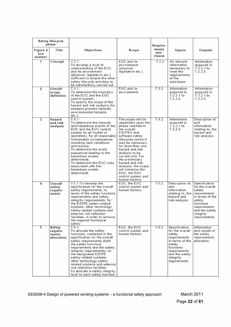
2 .4 .1 The AS61508 Safe ty l i fecyc le concept
The AS61508 standard includes a 16-phase generic lifecycle process, shown here in Figure 5.
Figure 5 – AS61508 Safety lifecycle
This safety lifecycle simply formalises the normal design process that should
be followed from concept through to de-commissioning. A rigid framework of tasks, documentation and verifications ensures that a thorough and repeatable process is followed and ensures that adequate checking and record keeping is performed. These 16 phases can generally be divided into three fundamental stages – Analysis, Realisation and Operation.

Analysis covers lifecycle phases 1 to 5 from initial concept through to the
specification of safety system requirements.
Realisation covers lifecycle phases 6 to 13 from design through to the safety verification of the commissioned system.
Operation covers lifecycle phases 14 to 16 from when the safety system becomes operational through to the time it is modified or decommissioned.
The key objectives, activities and deliverables for each phase (from AS61508-1) are shown in the following series of tables.
EES008-4 Design of powered winding systems – a functional safety approach March 2011
Page 21 of 81
EES008-4 Design of powered winding systems – a functional safety approach March 2011
Page 22 of 81
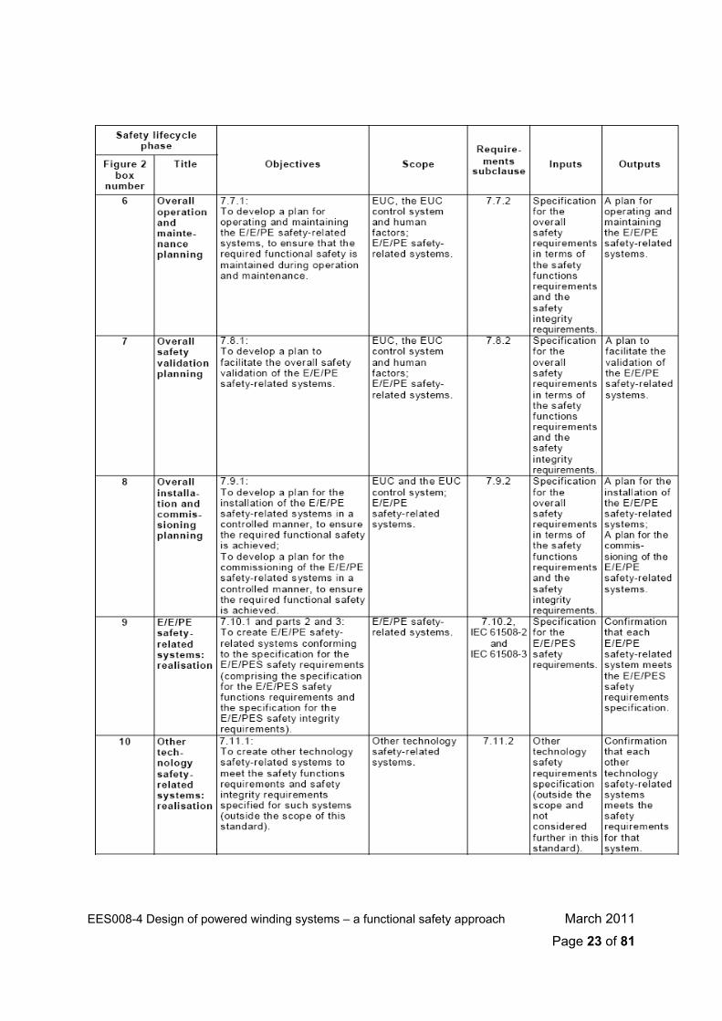
EES008-4 Design of powered winding systems – a functional safety approach March 2011
Page 23 of 81
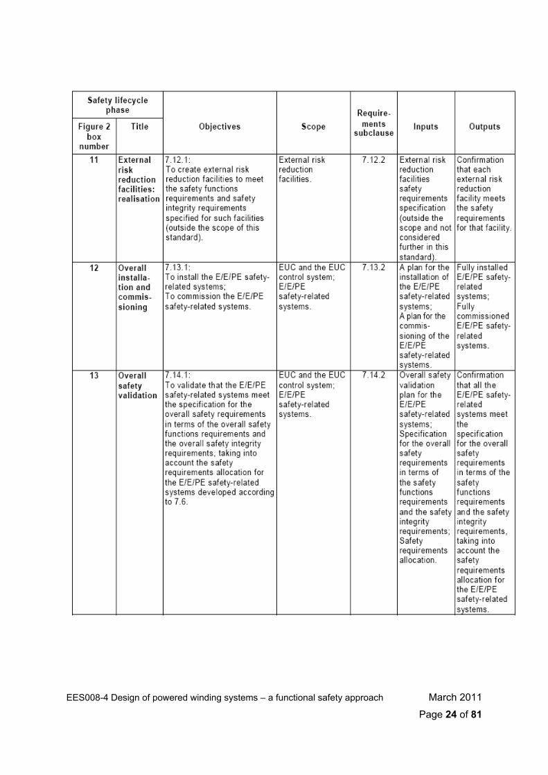
EES008-4 Design of powered winding systems – a functional safety approach March 2011
Page 24 of 81

EES008-4 Design of powered winding systems – a functional safety approach March 2011
Page 25 of 81
EES008-4 Design of powered winding systems – a functional safety approach March 2011
Page 26 of 81
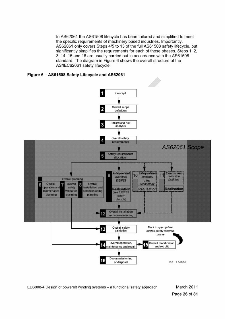
In AS62061 the AS61508 lifecycle has been tailored and simplified to meet
the specific requirements of machinery based industries. Importantly, AS62061 only covers Steps 4/5 to 13 of the full AS61508 safety lifecycle, but significantly simplifies the requirements for each of those phases. Steps 1, 2, 3, 14, 15 and 16 are usually carried out in accordance with the AS61508 standard. The diagram in Figure 6 shows the overall structure of the AS/IEC62061 safety lifecycle.
Figure 6 – AS61508 Safety Lifecycle and AS62061
AS62061 ScopeAS62061 Scope

EES008-4 Design of powered winding systems – a functional safety approach March 2011
Page 27 of 81
AS62061 substitutes its own 10 steps for Steps 4/5 to 13 of the AS61508
process. These 10 steps are shown separately in Figure 7 below.
Figure 7 – AS62061 SRECS Design Process
3. Worked Example of the Funct ional Safety Approach as appl ied to a Powered Winding
System
The requirements and processes presented here are derived from AS61508-1, but make allowance for the fact that the AS62061 lifecycle may be followed for machinery applications for part of the safety lifecycle.
3 . 1 A S 6 1 5 0 8 S t e p 1 - C o n c e p t
Objective/s Develop an understanding of the EUC and its environment (ie. physical, legislative etc.) sufficient to enable other safety lifecycle activities to be carried out.
Requirements From AS61508-1 Clause 7.2.2, the following must be achieved:
• A thorough familiarity shall be acquired of the EUC, its required control functions and its physical environment,
• The likely sources of hazard shall be determined, • Information about the hazard sources shall be obtained (eg. toxicity,
explosive conditions, corrosiveness, reactivity, flammability etc.), • Information about the current safety regulations (national and
international) shall be obtained, • Hazards due to the interaction with other EUCs (installed or to be
installed) in the proximity of the EUC shall be considered, • The information and results acquired shall be documented and
maintained throughout the overall safety lifecycle. Implementation
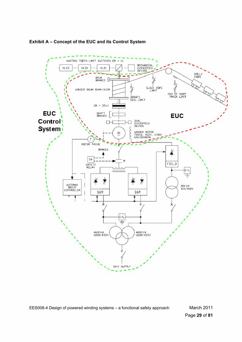
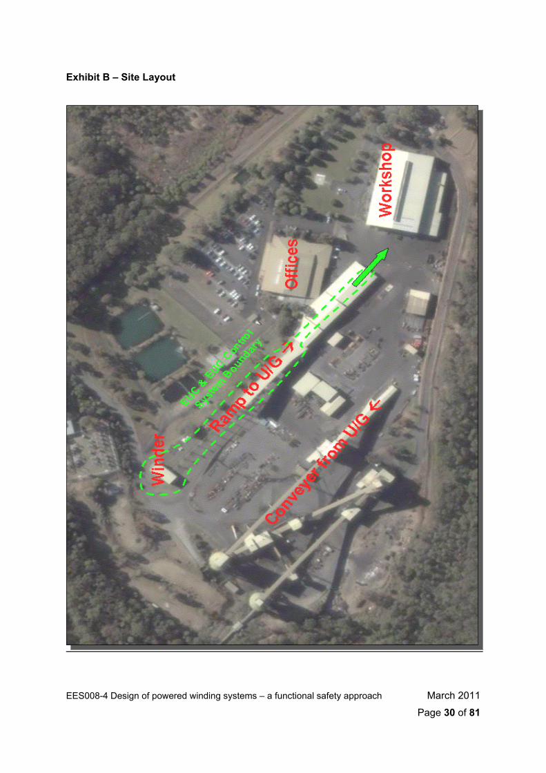
This is an important but brief step. The main outcome should be that the overall concept of the EUC, its control system and its operating environment should be understood. An overview schematic diagram should be prepared showing the boundaries of the EUC, its control system, taking into consideration the proposed site and operating environment. An example is provided in Exhibits A and B below.
EES008-4 Design of powered winding systems – a functional safety approach March 2011
Page 28 of 81
EES008-4 Design of powered winding systems – a functional safety approach March 2011
Page 29 of 81
Exhibit A – Concept of the EUC and its Control System
EES008-4 Design of powered winding systems – a functional safety approach March 2011
Page 30 of 81
Exhibit B – Site Layout

EES008-4 Design of powered winding systems – a functional safety approach March 2011
Page 31 of 81
The legislative and other requirements should also be sourced and
understood as they apply to the project. For the functional safety aspects of a mine winder project the following information provided in Exhibit C will be most relevant.
Exhibit C – Survey of Safety Regulations Excerpt from the NSW Coal Mine Health and Safety Regulation 2006:
Clause 13(1)(e)(v)…. to provide electrical safeguards for electrical and non-electrical hazards, with a probability of failure appropriate to the degree of risk posed by the hazard. Clause 13(1)(f) (viii)…. to provide electrical safeguards for electrical and non-electrical hazards with a probability of failure appropriate to the degree of risk posed
Excerpt from Legislative Update No. 5/2007:
Information on hazards and learnings on risk management from previous
safety incidents with similar EUCs should be sourced and appreciated early in the safety lifecycle. Previous risk assessments on similar EUCs will allow a greater understanding of the types of hazards likely to be encountered. The following excerpts in Exhibit D would normally be available for the manager of a winder project.

EES008-4 Design of powered winding systems – a functional safety approach March 2011
Page 32 of 81
Exhibit D – Survey of Hazards and Incident History Safety Alert 99-07
Safety Alert 00-04
The type of information indicated above should be sourced as soon as
possible after the commencement of the project and a Safety Lifecycle Dossier should be initiated. Information, analysis and results should be placed into the Safety Lifecycle Folder, which may be indexed by lifecycle step.
Verification No verification is required at this point. This step shall be verified following AS61508 Step3.
Documentation
• Functional specifications, overview drawings and concept schematics of the EUC and its control system.
• Copies of previous risk assessments conducted by the EUC supplier and/or by other users.
• Literature review of previous safety incident and accident data. • MSDS for hazardous materials. • Copies of relevant extracts from safety legislation, regulations,
codes of practice and safety alerts. • Proposed layout drawings and concept of operations for the EUC at
the site, including its interactions with other equipment and with people (including operators, workers, maintainers and the public).
3 . 2 A S 6 1 5 0 8 S t e p 2 – O v e r a l l S c o p e D e f i n i t i o n
AS61508 Steps 1 and 2 may practically be conducted together.
Objective/s 1. To determine the boundary of the EUC and the EUC control system.
2. To specify the scope of the hazard and risk analysis.
Requirements From AS61508-1 Clause 7.3.2, the following must be achieved: • The physical environment, including the EUC and EUC control
system to be included in the scope of the hazard and risk analysis, shall be specified,
• The external events to be taken into account in the hazard and risk analysis shall be specified,
• The sub-systems associated with the hazards shall be specified, • The type of accident-initiating events that need to be considered
(eg. component failures, human error, dependent failures) shall be specified,
• The information and results acquired shall be documented and maintained throughout the overall safety lifecycle.
EES008-4 Design of powered winding systems – a functional safety approach March 2011
Page 33 of 81
Implementation For machinery applications, AS62061 specifies that a Functional Safety
Plan should be drawn up early in the safety lifecycle for each design project, and updated as necessary. AS61508 Step 2 is an appropriate point for this plan to be produced.
The plan should address the requirements listed above and include procedures for control of the safety lifecycle activities. The plan should be placed in the Safety Lifecycle Dossier. The content of the Functional Safety Plan should depend upon the specific circumstances, which can include:
• Size of project; • Degree of complexity; • Degree of novelty of design and technology; • Degree of standardization of design features; • Possible consequence (s) in the event of failure.
The Functional Safety Plan must be implemented to ensure prompt follow-up and satisfactory resolution of issues arising from risk assessment, specification and design activities and the verification and validation activities.
For a mine winder project the 10-point Functional Safety Plan provided in Exhibit E on the following page should be used as a guide.
EES008-4 Design of powered winding systems – a functional safety approach March 2011
Page 34 of 81

EES008-4 Design of powered winding systems – a functional safety approach March 2011
Page 35 of 81
Exhibit E – 10 point Functional Safety Plan
In particular, at point #8, the Functional Safety Plan should detail the need
for a Configuration Management strategy to manage engineering changes to the mine winder, its control system and its safety functions. This strategy should refer to and follow established engineering change management processes where applicable, but also ensure that the following aspects are addressed, per Exhibit F.

EES008-4 Design of powered winding systems – a functional safety approach March 2011
Page 36 of 81
Exhibit F – Engineering Change Management Strategy
In a similar vein, AS62061 requires that a Verification Plan and a Validation Plan must be produced as part of the Functional Safety Plan. These may practically be produced as a combined plan, but must address the following issues, per Exhibit G and H.
For a mine winder project, three (3) verifications should be carried out at AS61508 Step 3, and AS62061 Steps 5 and 8. A final validation of the implemented safety system should be carried out during AS61508 Step 13.
Details on the specific requirements of these verification and validation activities are provided in the sections dealing with those steps of the functional safety lifecycle. These details should be included in the verification and validation plans.
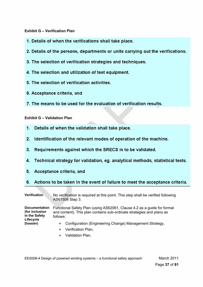
Exhibit G – Verification Plan
Exhibit G – Validation Plan
Verification No verification is required at this point. This step shall be verified following
AS61508 Step 3.
Documentation (for inclusion in the Safety Lifecycle Dossier)
Functional Safety Plan (using AS62061, Clause 4.2 as a guide for format and content). This plan contains sub-ordinate strategies and plans as follows:
• Configuration (Engineering Change) Management Strategy, • Verification Plan, • Validation Plan.
EES008-4 Design of powered winding systems – a functional safety approach March 2011
Page 37 of 81

3 . 3 A S 6 1 5 0 8 S t e p 3 – H a z a r d a n d R i s k A n a l ys i s
Objective/s 1. Determine the hazards and hazardous events of the EUC and EUC control system (in all modes of operation for all reasonably foreseeable circumstances, including fault conditions and misuse).
2. Determine the event sequences leading to the hazardous events.
3. Determine the EUC risks associated with the hazardous events.
Requirements From AS61508-1 Clause 7.4.2 the following must be achieved:
• A hazard and risk analysis shall be conducted, based on the scope specified in AS61508 Step 2.
• Consideration shall be given to the elimination of hazards. • The event sequences leading to the hazards shall be determined. • The likelihood of the hazardous events shall be evaluated. • The potential consequences associated with the hazardous events
shall be determined. • The EUC risk shall be evaluate, or estimated for each determined
hazardous event. • These requirements may be met by either a qualitative or quantitative
risk analysis technique. • The techniques applied will depend upon a number of factors,
including: o Specific hazards and the consequences, o Application sector and accepted good practices, o Legal and safety regulatory requirements, o The EUC risk, o The availability of accurate data upon which the analysis is to
be based.
• The hazard and risk analysis shall also consider the following: o The contributing components of each hazard, o The consequences and likelihood of the event sequences with
which each hazardous event is associated, o The Necessary Risk Reduction for each hazardous event
(based upon a notion of the tolerable risk), o The measures used to reduce of remove hazards and risks, o The assumptions made during the analysis of the risks.
• The information and results acquired shall be documented and maintained throughout the overall safety lifecycle.
EES008-4 Design of powered winding systems – a functional safety approach March 2011
Page 38 of 81
EES008-4 Design of powered winding systems – a functional safety approach March 2011
Page 39 of 81
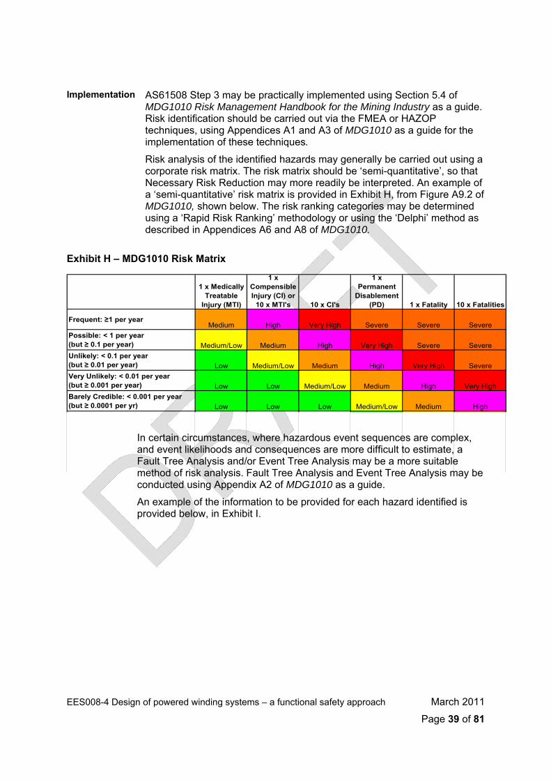
Implementation AS61508 Step 3 may be practically implemented using Section 5.4 of
MDG1010 Risk Management Handbook for the Mining Industry as a guide. Risk identification should be carried out via the FMEA or HAZOP techniques, using Appendices A1 and A3 of MDG1010 as a guide for the implementation of these techniques.
Risk analysis of the identified hazards may generally be carried out using a corporate risk matrix. The risk matrix should be ‘semi-quantitative’, so that Necessary Risk Reduction may more readily be interpreted. An example of a ‘semi-quantitative’ risk matrix is provided in Exhibit H, from Figure A9.2 of MDG1010, shown below. The risk ranking categories may be determined using a ‘Rapid Risk Ranking’ methodology or using the ‘Delphi’ method as described in Appendices A6 and A8 of MDG1010.
Exhibit H – MDG1010 Risk Matrix
1 x Medically Treatable
Injury (MTI)
1 x Compensible Injury (CI) or
10 x MTI's 10 x CI's
1 x Permanent
Disablement (PD) 1 x Fatality 10 x Fatalities
Frequent: ≥1 per yearMedium High Very High Severe Severe Severe
ssible: < 1 per year ≥ 0.1 per year) Medium/Low Medium High Very High Severe Severe
ikely: < 0.1 per year ≥ 0.01 per year) Low Medium/Low Medium High Very High Severe
Po(but Unl(but
V
ery Unlikely: < 0.01 per year ≥ 0.001 per year) Low Low Medium/Low Medium High Very High
arely Credible: < 0.001 per year (but ≥ 0.0001 per yr) Low Low Low Medium/Low Medium High
(but
In certain circumstances, where hazardous event sequences are complex, and event likelihoods and consequences are more difficult to estimate, a Fault Tree Analysis and/or Event Tree Analysis may be a more suitable method of risk analysis. Fault Tree Analysis and Event Tree Analysis may be conducted using Appendix A2 of MDG1010 as a guide.
An example of the information to be provided for each hazard identified is provided below, in Exhibit I.
B

EES008-4 Design of powered winding systems – a functional safety approach March 2011
Page 40 of 81
Exhibit I – Hazard Analysis
The risk analysis of each hazard should be based upon known safety criteria
and should endeavour to assess what the level of risk is expected to be with no risk controls in place. The concept of what is a ‘tolerable’ risk should also be established, so as to establish the Necessary Risk Reduction to be achieved by the risk controls. A pictorial example of the information to be provided for each hazard is provided below in Exhibit J, which plots the hazard already analysed in Exhibit I and relates it to a notional ‘tolerable risk’ level.
Exhibit J – Risk Analysis
1 x Medically Treatable
Injury (MTI)
1 x Compensible Injury (CI) or
10 x MTI's 10 x CI's
1 x Permanent
Disablement (PD) 1 x Fatality 10 x Fatalities
Frequent: ≥1 per yearMedium High Very High Severe Severe Severe
Possible: < 1 per year (but ≥ 0.1 per year) Medium/Low Medium High Very High Severe SevereUnlikely: < 0.1 per year (but ≥ 0.01 per year) Low Medium/Low Medium High Very High SevereVery Unlikely: < 0.01 per year (but ≥ 0.001 per year) Low Low Medium/Low Medium High Very HighBarely Credible: < 0.001 per year (but ≥ 0.0001 per yr) Low Low Low Medium/Low Medium High
Low Medium/Low Medium
Low Medium/Low
Low Tolerable risk boundary
Necessary
Risk

Verification The Functional Safety Plan developed during AS61508 Step 2 will have
included the requirement for a Verification Plan. Generally, AS61508 Steps 1, 2 and 3 should be verified at the conclusion of AS61508 Step 3. At this point, the project has been scoped, a Functional Safety Plan has been produced, and hazard and risk assessments have been carried out.
The general idea of this verification is to demonstrate that the outputs of AS61508 Steps 1-3 meet in all respects the objectives and requirements for those steps, that is:
• The requirements of each step have been technically satisfied.
• The Safety Lifecycle Dossier has the full complement of input information, analysis and documentation and results appropriate for this stage of the safety lifecycle.
• The final result, as embodied in the Hazard and Risk Analysis Report, is appropriate for use in subsequent steps of the safety lifecycle.
The general requirements for verification are that:
• The verification should be carried out according to the Verification Plan.
• The information and results acquired shall be documented and maintained throughout the overall safety lifecycle.
Verification of AS61508 Step 3 (Hazard and Risk Analysis) may be carried out in accordance with MDG1014 Guide to Reviewing a Risk Assessment of Mine Equipment and Operations, Appendix 1.
Documentation (for inclusion in the Safety Lifecycle Dossier)
• Hazard and Risk Analysis Report, using Section 7 of MDG1010 Risk Management Handbook for the Mining Industry as a guide).
• Associated information used during the hazard and risk analysis (eg. corporate risk matrix, drawings and specifications etc.).
• Verification Report for AS61508 Steps 1, 2 and 3.
• A statement of the verifier’s competence and independence.
A S 6 1 5 0 8 S t e p 4 – O v e r a l l S a f e t y R e q u i r e m e n t s
AS61508 Step 4 and AS62061 Steps 1-4 may practically be conducted together. After AS61508 Step 4, the AS62061 lifecycle may be commenced for machinery applications, so there is a transition from AS61508 requirements to AS62061 requirements at this point.
EES008-4 Design of powered winding systems – a functional safety approach March 2011
Page 41 of 81

Objective/s Develop the specification for the overall safety requirements in terms of
Safety Functions requirements and safety integrity requirements for the E/E/PE Safety-Related Systems, other technology Safety-Related Systems and external risk reduction facilities in order to achieve the required functional safety.
Requirements From AS61508-1 Clause 7.5.2, the following must be achieved:
• Safety functions necessary to ensure the required functional safety shall be specified.
• The Necessary Risk Reduction shall be determined for each determined hazardous event. The risk reduction may be determined in a quantitative or qualitative manner.
• For situations where an application sector standard exists, which includes appropriate methods for determining the Necessary Risk Reduction, then such standards may be used to meet the above requirement,
• Where failures of the EUC control system place a demand on one or more of the E/E/PE Safety-Related Systems, other technology Safety-Related Systems and/or external risk reduction facilities and where the intention is not to designate the EUC control system as a Safety-Related System, the following shall apply: o The dangerous failure rate claimed for the EUC control system
shall be supported by data acquired through operational experience, reliability analysis or industry databases,
o The dangerous failure rate that can be claimed for the EUC control system shall not be lower than 10-5 dangerous failures per hour.
o All reasonably foreseeable dangerous failure modes of the EUC control system be determined,
o The EUC control system shall be separate and independent from the E/E/PE Safety-Related Systems, other technology Safety-Related Systems and external risk reduction facilities.
• If the above requirements cannot be met, then the EUC control system shall be designated as a safety-related system and a Safety Integrity Level (SIL) shall be applied to it based on the failure rate that is claimed for it.
• The safety integrity requirements in terms of the Necessary Risk Reduction shall be specified for each safety function.
• The specification of Safety Functions and the specification of the safety integrity requirements together shall constitute the specification for the overall safety requirements.
• The information and results acquired shall be documented and maintained throughout the overall safety lifecycle.
EES008-4 Design of powered winding systems – a functional safety approach March 2011
Page 42 of 81

EES008-4 Design of powered winding systems – a functional safety approach March 2011
Page 43 of 81
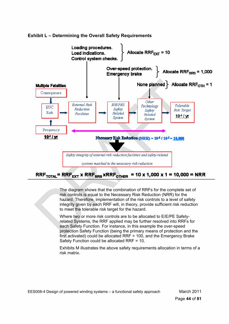
Implementation At this point the overall safety integrity requirements of the risk controls are
established and expressed as Risk Reduction Factors (RRF), ie. the factor by which the risk will be reduced by the particular risk control. Importantly, a ‘tolerable’ risk target must be established before the RRF’s for each risk control can be determined.
‘Tolerable’ risk has usually been derived from a number of sources - corporate or industry risk matrices, reference material on societal risk, or it may have been otherwise specified. Exhibit K shows a general range of values for ‘tolerable’ risk that have been used previously within the European Union. This graph is provided for information only.
Exhibit K – Tolerable Risk Frequencies
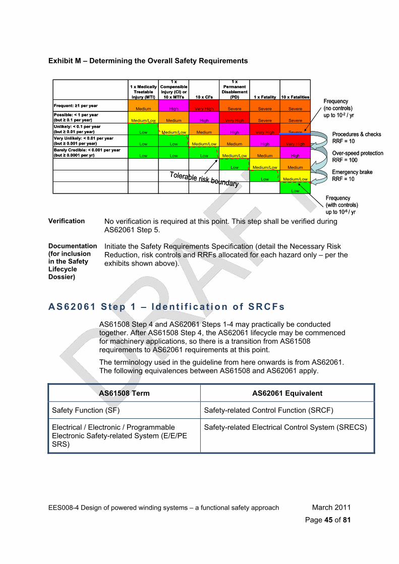
In the risk matrix given in MDG1010 Figure A9, (see Exhibit J) the
‘tolerable’ risk frequency for a single fatality is implied to be 10-5 / yr, and a multiple (~10) fatality event is implied to have a tolerable risk frequency of 10-6 / yr.
In the hazard analysis given in Exhibit I the multiple-fatality winder overspeed hazard is estimated to have a frequency of up to 10-2 / yr, with no risk controls in place. Therefore, to reduce this risk to a ‘tolerable’ level (ie. a hazard frequency of less than 10-6 / yr), the risk controls must achieve a Necessary Risk Reduction of 10-2 / 10-6, that is, 10,000. Exhibit L shows how this Necessary Risk Reduction may be apportioned among the various risk controls that were proposed for the hazard in Exhibit I.
EES008-4 Design of powered winding systems – a functional safety approach March 2011
Page 44 of 81
Exhibit L – Determining the Overall Safety Requirements
The diagram shows that the combination of RRFs for the complete set of
risk controls is equal to the Necessary Risk Reduction (NRR) for the hazard. Therefore, implementation of the risk controls to a level of safety integrity given by each RRF will, in theory, provide sufficient risk reduction to meet the tolerable risk target for the hazard.
Where two or more risk controls are to be allocated to E/E/PE Safety-related Systems, the RRF applied may be further resolved into RRFs for each Safety Function. For instance, in this example the over-speed protection Safety Function (being the primary means of protection and the first activated) could be allocated RRF = 100, and the Emergency Brake Safety Function could be allocated RRF = 10.
Exhibits M illustrates the above safety requirements allocation in terms of a risk matrix.
EES008-4 Design of powered winding systems – a functional safety approach March 2011
Page 45 of 81
Exhibit M – Determining the Overall Safety Requirements
1 x Medically Treatable
Injury (MTI)
1 x Compensible Injury (CI) or
10 x MTI's 10 x CI's
1 x Permanent
Disablement (PD) 1 x Fatality 10 x Fatalities
Frequent: ≥1 per yearMedium High Very High Severe Severe Severe
Possible: < 1 per year (but ≥ 0.1 per year) Medium/Low Medium High Very High Severe SevereUnlikely: < 0.1 per year (but ≥ 0.01 per year) Low Medium/Low Medium High Very High Severe
Verification No verification is required at this point. This step shall be verified during
AS62061 Step 5.
Documentation (for inclusion in the Safety Lifecycle Dossier)
Initiate the Safety Requirements Specification (detail the Necessary Risk Reduction, risk controls and RRFs allocated for each hazard only – per the exhibits shown above).
A S 6 2 0 6 1 S t e p 1 – I d e n t i f i c a t i o n o f S R C F s
AS61508 Step 4 and AS62061 Steps 1-4 may practically be conducted together. After AS61508 Step 4, the AS62061 lifecycle may be commenced for machinery applications, so there is a transition from AS61508 requirements to AS62061 requirements at this point.
The terminology used in the guideline from here onwards is from AS62061. The following equivalences between AS61508 and AS62061 apply.
AS61508 Term AS62061 Equivalent
Safety Function (SF) Safety-related Control Function (SRCF)
Electrical / Electronic / Programmable Electronic Safety-related System (E/E/PE SRS)
Safety-related Electrical Control System (SRECS)
Very Unlikely: < 0.01 per year (but ≥ 0.001 per year) Low Low Medium/Low Medium High Very HighBarely Credible: < 0.001 per year (but ≥ 0.0001 per yr) Low Low Low Medium/Low Medium High
Low Medium/Low Medium
Low Medium/Low
Low
Tolerable risk boundary
Procedures & checksRRF = 10
Over-speed protectionRRF = 100
Emergency brakeRRF = 10
Frequency(no controls)up to 10-2 / yr
Frequency(with controls)up to 10-6 / yr
1 x Medically Treatable
Injury (MTI)
1 x Compensible Injury (CI) or
10 x MTI's 10 x CI's
1 x Permanent
Disablement (PD) 1 x Fatality 10 x Fatalities
Frequent: ≥1 per yearMedium High Very High Severe Severe Severe
Possible: < 1 per year (but ≥ 0.1 per year) Medium/Low Medium High Very High Severe SevereUnlikely: < 0.1 per year (but ≥ 0.01 per year) Low Medium/Low Medium High Very High SevereVery Unlikely: < 0.01 per year (but ≥ 0.001 per year) Low Low Medium/Low Medium High Very HighBarely Credible: < 0.001 per year (but ≥ 0.0001 per yr) Low Low Low Medium/Low Medium High
Low Medium/Low Medium
Low Medium/Low
Low
Frequency(no controls)up to 10-2 / yr
Procedures & checksRRF = 10
Over-speed protectionRRF = 100
Emergency brakeRRF = 10
Tolerable risk boundary
Frequency(with controls)up to 10-6 / yr
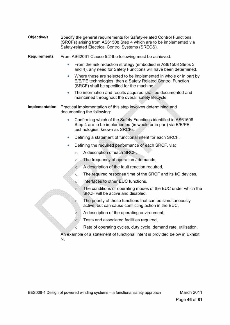
Objective/s Specify the general requirements for Safety-related Control Functions
(SRCFs) arising from AS61508 Step 4 which are to be implemented via Safety-related Electrical Control Systems (SRECS).
Requirements From AS62061 Clause 5.2 the following must be achieved:
• From the risk reduction strategy (embodied in AS61508 Steps 3 and 4), any need for Safety Functions will have been determined.
• Where these are selected to be implemented in whole or in part by E/E/PE technologies, then a Safety Related Control Function (SRCF) shall be specified for the machine.
• The information and results acquired shall be documented and maintained throughout the overall safety lifecycle.
Implementation Practical implementation of this step involves determining and documenting the following:
• Confirming which of the Safety Functions identified in AS61508 Step 4 are to be implemented (in whole or in part) via E/E/PE technologies, known as SRCFs.
• Defining a statement of functional intent for each SRCF.
• Defining the required performance of each SRCF, via:
o A description of each SRCF,
o The frequency of operation / demands,
o A description of the fault reaction required,
o The required response time of the SRCF and its I/O devices,
o Interfaces to other EUC functions,
o The conditions or operating modes of the EUC under which the SRCF will be active and disabled,
o The priority of those functions that can be simultaneously active, but can cause conflicting action in the EUC,
o A description of the operating environment,
o Tests and associated facilities required,
o Rate of operating cycles, duty cycle, demand rate, utilisation.
An example of a statement of functional intent is provided below in Exhibit N.
EES008-4 Design of powered winding systems – a functional safety approach March 2011
Page 46 of 81
EES008-4 Design of powered winding systems – a functional safety approach March 2011
Page 47 of 81
Exhibit N – Identification of SRCFs
Verification No verification required at this point. This step shall be verified during
AS62061 Step 5.
Documentation (for inclusion in the Safety Lifecycle Dossier)
List of all identified SRCFs and their statements of functional intent and performance parameters (eg. demand rates, response times, action taken when initiated, etc.). This information may be collated with the Safety Requirements Specification already initiated in AS61508 Step 4.
A S 6 2 0 6 1 S t e p 2 – I n i t i a l C o n c e p t
AS61508 Step 4 and AS62061 Steps 1- 4 may practically be conducted concurrently.
Objective/s Decompose each SRCF into function blocks to create an initial concept for how they will be implemented in the SRECS.
Requirements From AS62061 Clause 6.6.2 the following must be achieved:
• Each SRCF shall be decomposed into a structure of function blocks. • An initial concept of the SRCF architecture shall be created in
accordance with the structure of the function blocks. • The information and results acquired shall be documented and
maintained throughout the overall safety lifecycle.

Implementation The breakdown of the SRCF into function blocks creates an initial concept
for the architecture of the SRECS. The safety requirements for each of the function blocks will be based upon the overall safety requirements for the SRCF. An example of a breakdown of the over-speed protection SRCF into functional blocks is provided here in Exhibit O.
Exhibit O – Initial Concept
Verification No verification required at this point. This step shall be verified during
AS62061 Step 5.
Documentation (for inclusion in the Safety Lifecycle Dossier)
SRECS Concept Design document including SRECS decomposition diagrams into function blocks (as shown above) for each SRCF. This information may be collated with the Safety Requirements Specification initiated in AS61508 Step 4 and updated during AS62061 Step 1.
A S 6 2 0 6 1 S t e p 3 – D e t a i l e d S a f e t y R e q u i r e m e n t s o f F u n c t i o n a l B l o c k s
AS61508 Step 4 and AS62061 Steps 1- 4 may practically be conducted together.
Objective/s Specify the safety requirements of each of the functional blocks used by the SRCFs.
EES008-4 Design of powered winding systems – a functional safety approach March 2011
Page 48 of 81
Requirements From AS62061 Clause 6.6.2.1.6 (using the information sourced in
AS62061 Step 1 and 2), as follows: • The safety requirements for each function block shall be as
specified in the safety requirements specification of the corresponding SRCF. These shall comprise: o Functional requirements (eg. input information, internal
operation (logic) and output of the function block). o Safety integrity requirements.
• The information and results acquired shall be documented and maintained throughout the safety lifecycle.
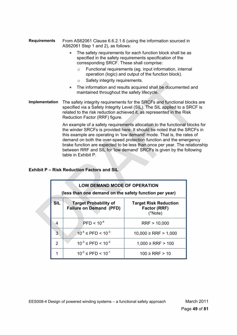
Implementation The safety integrity requirements for the SRCFs and functional blocks are specified via a Safety Integrity Level (SIL). The SIL applied to a SRCF is related to the risk reduction achieved it, as represented in the Risk Reduction Factor (RRF) figure.
An example of a safety requirements allocation to the functional blocks for the winder SRCFs is provided here. It should be noted that the SRCFs in this example are operating in ‘low demand’ mode. That is, the rates of demand on both the over-speed protection function and the emergency brake function are expected to be less than once per year. The relationship between RRF and SIL for ‘low demand’ SRCFs is given by the following table in Exhibit P.
Exhibit P – Risk Reduction Factors and SIL
LOW DEMAND MODE OF OPERATION (less than one demand on the safety function per year)
SIL Target Probability of Failure on Demand (PFD)
Target Risk Reduction Factor (RRF)
(*Note)
4 PFD < 10-4 RRF > 10,000
3 10-4 ≤ PFD < 10-3 10,000 ≥ RRF > 1,000
2 10-3 ≤ PFD < 10-2 1,000 ≥ RRF > 100
1 10-2 ≤ PFD < 10-1 100 ≥ RRF > 10
EES008-4 Design of powered winding systems – a functional safety approach March 2011
Page 49 of 81

Therefore, the SILs allocated to the SRCFs are as follows:
SRCF Description RRF Allocated SIL Target
1 Over-speed Protection 100 2
2 Emergency Brake 10 1
These following diagrams in Exhibit Q show how the SIL is allocated to the
function blocks of each SRCF. Importantly, the implementation of these SRCFs must achieve independence as they are both related to the control of the same hazard. Therefore, there can be no sharing of functional blocks between the two SRCFs. Furthermore, the SRCF’s will need to be implemented via separate SRECS hardware.
EES008-4 Design of powered winding systems – a functional safety approach March 2011
Page 50 of 81

EES008-4 Design of powered winding systems – a functional safety approach March 2011
Page 51 of 81
Exhibit Q – Safety Requirements Allocation
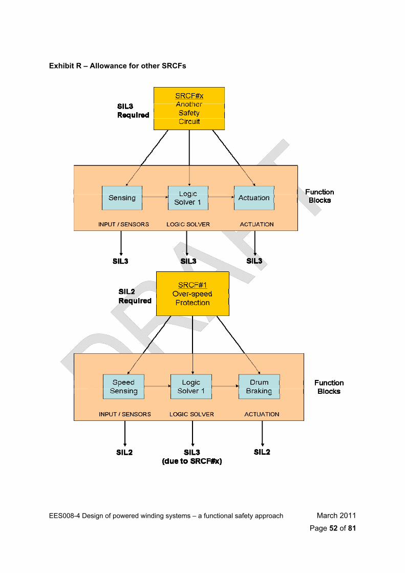
Function blocks may be shared between SRCFs used to control different
hazards. The overall SIL requirement for such function blocks must be the maximum of the SILs of the SRCFs being implemented, An example is given below in Exhibit R where an SRCF used to control a different risk is to use the same logic resolver function block. This effectively raises the SIL required for Logic Solver 1 to SIL3.
EES008-4 Design of powered winding systems – a functional safety approach March 2011
Page 52 of 81
Exhibit R – Allowance for other SRCFs
Allocating SILs to function blocks may be potentially confusing where
numerous SRCFs are to be implemented for an EUC. A master listing of the SRCFs and function blocks should be produced, showing the SIL requirements of each function block, in order to satisfy the SIL requirements of all of the SRCFs being implemented, and maintaining independence between SRCFs used as controls against the same hazard.
Verification No verification is required at this point. This step shall be verified during AS62061 Step 5.
Documentation (for inclusion in the Safety Lifecycle Dossier)
SRECS Sub–system Safety Requirements Specification, including a list of SIL allocations to each of the function blocks being utilised in SRCFs, as described above. This information may be collated with the Safety Requirements Specification initiated in AS61508 Step 4 and updated during AS62061 Steps 1 and 2.
A S 6 2 0 6 1 S t e p 4 – A l l o c a t e F u n c t i o n B l o c k s t o S R E C S S u b - s ys t e m s
AS61508 Step 4 and AS62061 Steps 1- 4 may practically be conducted together.
Objective/s Create an initial concept for the physical implementation of the SRCFs with SRECS sub-systems.
Requirements From AS62061 Clause 6.6.2 the following must be achieved:
• Each function block shall be allocated to a sub-system within the architecture of the SRECS.
• More than one function block may be allocated to one sub-system. • The safety requirements for SRCF sub-systems shall be those of
the function blocks allocated. • If more than one functional block is allocated to a sub-system, then
the highest integrity requirement applies. • Where software is to be utilised by SRECS sub-systems which
implement the function blocks, a Software Safety Requirements Specification shall also be produced.
• The information and results acquired shall be documented and maintained throughout the overall safety lifecycle.
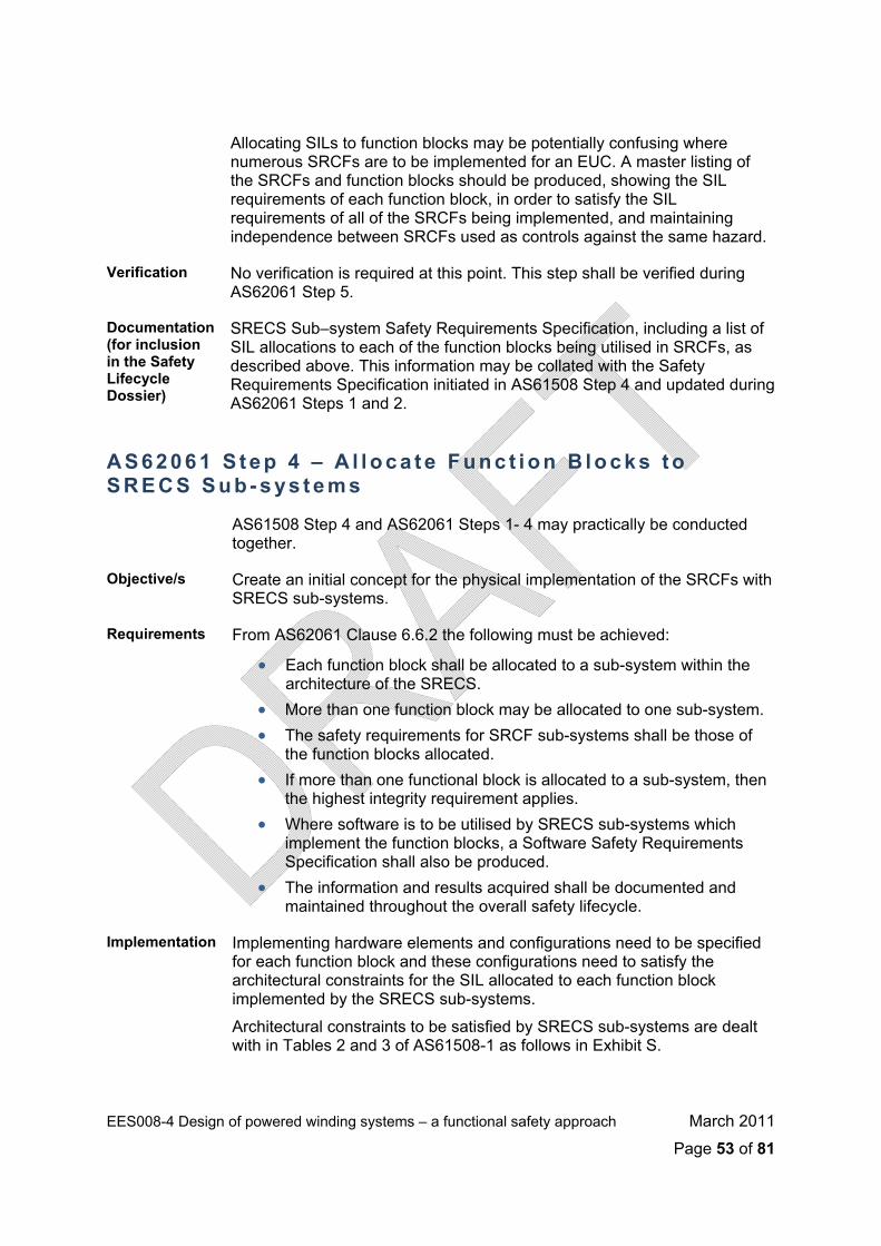
Implementation Implementing hardware elements and configurations need to be specified for each function block and these configurations need to satisfy the architectural constraints for the SIL allocated to each function block implemented by the SRECS sub-systems.
Architectural constraints to be satisfied by SRECS sub-systems are dealt with in Tables 2 and 3 of AS61508-1 as follows in Exhibit S.
EES008-4 Design of powered winding systems – a functional safety approach March 2011
Page 53 of 81
Exhibit S – Architectural Constraints
A sub-system can be regarded as Type A if, for the components required
to achieve the safety function:
1. The failure modes of all constituent components are well defined; and
2. The behaviour of the subsystem under fault conditions can be completely determined; and
3. There is sufficient dependable failure data from field experience to show that the claimed rates of failure for detected and undetected dangerous failures are met.
A sub-system can be regarded as Type B if, for the components required to achieve the safety function:
1. The failure mode of at least one constituent component is not well defined; or
2. The behaviour of the sub-system under fault cannot be completely determined; or
3. There is insufficient dependable failure data from field experience to support claims for rates of failure for detected and undetected dangerous failures.
EES008-4 Design of powered winding systems – a functional safety approach March 2011
Page 54 of 81
A hardware fault tolerance, HWFT, of N means that N+1 faults would be
needed to cause a loss of the safety function. In determining the hardware fault tolerance no account can be taken of other measures that may control the effects of faults, such as diagnostics. Also, where one fault directly leads to the occurrence of one or more subsequent faults, these are considered as a single fault.
The Safe Failure Fraction, SFF, of a sub-system is defined as the ratio of the rates of safe failures and dangerous detected failures of the sub-system to the total failure rate of the sub-system. SFF of a component or equipment is usually determined via a reliability prediction.
An example of a function block allocation to SRECS sub-systems for SRCF#1 (Winder Over-speed Protection) and consideration of SRECS sub-system architecture is provided below in Exhibits T and U. In this example, the Logic Solver function is to be implemented via a Safety PLC, the speed sensing function is implemented via a set of dual redundant speed sensors and actuation via dual redundant contactors controlling the braking action. It is also important to allocate diagnostic capabilities to the SRECS sub-systems where applicable. Diagnostics may be implemented within the hardware elements in each sub-system, or may be solely-based within the Logic Solver function.
EES008-4 Design of powered winding systems – a functional safety approach March 2011
Page 55 of 81

EES008-4 Design of powered winding systems – a functional safety approach March 2011
Page 56 of 81
Exhibit T – Allocation of Function Blocks to SRECS sub-systems
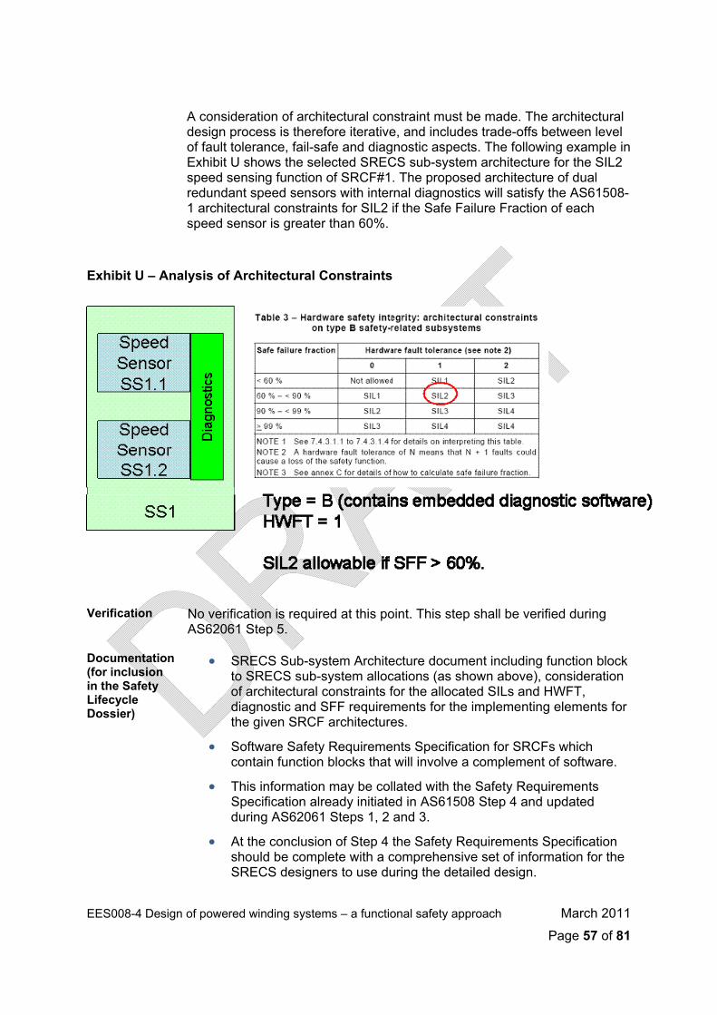
EES008-4 Design of powered winding systems – a functional safety approach March 2011
Page 57 of 81
A consideration of architectural constraint must be made. The architectural
design process is therefore iterative, and includes trade-offs between level of fault tolerance, fail-safe and diagnostic aspects. The following example in Exhibit U shows the selected SRECS sub-system architecture for the SIL2 speed sensing function of SRCF#1. The proposed architecture of dual redundant speed sensors with internal diagnostics will satisfy the AS61508-1 architectural constraints for SIL2 if the Safe Failure Fraction of each speed sensor is greater than 60%.
Exhibit U – Analysis of Architectural Constraints
Verification No verification is required at this point. This step shall be verified during
AS62061 Step 5.
Documentation (for inclusion in the Safety Lifecycle Dossier)
• SRECS Sub-system Architecture document including function block to SRECS sub-system allocations (as shown above), consideration of architectural constraints for the allocated SILs and HWFT, diagnostic and SFF requirements for the implementing elements for the given SRCF architectures.
• Software Safety Requirements Specification for SRCFs which contain function blocks that will involve a complement of software.
• This information may be collated with the Safety Requirements Specification already initiated in AS61508 Step 4 and updated during AS62061 Steps 1, 2 and 3.
• At the conclusion of Step 4 the Safety Requirements Specification should be complete with a comprehensive set of information for the SRECS designers to use during the detailed design.
A S 6 2 0 6 1 S t e p 5 - V e r i f i c a t i o n
Objective/s To demonstrate that the outputs of the AS61508 Step 4 and AS62061 Steps 1 to 4 meet in all respects the objectives and requirements for those steps.
Requirements The general requirements are therefore, that:
• The verification should be carried out according to the verification plan.
• The information and results acquired shall be documented and maintained throughout the overall safety lifecycle.
Implementation The Functional Safety Plan developed during AS61508 Step 2 should have included a Verification Plan with the stipulation that verification be carried out at this step.
This verification should ensure that: • The steps as described in this guideline for AS61508 Step 4 and
AS62061 Steps 1- 4 have been followed and that the requirements of each step have been technically satisfied.
• The Safety Lifecycle Dossier has the full complement of input information, analysis and design documentation and results for this stage of the safety lifecycle.
• The results of the steps, as embodied in the Safety Requirements Specification produced at the end of AS62061 Step 4 are consistent with the inputs to the process and the methodologies applied.
The verification should be carried out by persons will an appropriate degree of independence and competence. Guidance on the level of competence of verifiers is given in AS61508-1 Annex B, which includes consideration of the following:
• Engineering knowledge appropriate to the application areas, • Engineering knowledge appropriate to the technology, • Safety engineering knowledge appropriate to the technology, • Knowledge of legal and regulatory framework, • Consequences of the failure of the SRECS – the higher the
consequences, the more rigorous should be the assessment of competence,
• SIL target of the SRECS – the higher the SIL, the more rigorous should be the assessment of competence,
• Novelty of the design, procedures or application – the newer or more untried the design, the more rigorous should be the assessment of competence,
• Consequences of the failure of the SRECS – the higher the consequences, the more rigorous should be the assessment of competence,
EES008-4 Design of powered winding systems – a functional safety approach March 2011
Page 58 of 81

• SIL target of the SRECS – the higher the SIL, the more rigorous
should be the assessment of competence,
• Novelty of the design, procedures or application – the newer or more untried the design, the more rigorous should be the assessment of competence,
• Previous experience and relevant to the specific duties to be performed,
• Relevance of qualifications to the specific duties to be performed.
Guidance on the appropriate level of independence of verifiers is provided in AS61508-1 Clause 8.2.14. Generally, a SIL1 SCRF may be verified by a suitably competent person within the same department who was not involved in the design. SIL2 requires a suitably competent person from a different department who was not involved in the design. SIL3 requires verification by an independent organisation which was not involved in the design.
Verification This step itself comprises a verification of AS61508 Step 4 and AS62061 Steps 1-4.
Documentation (for inclusion in the Safety Lifecycle Dossier)
• Verification document for AS61508 Step 4 and AS62061 Steps 1, 2, 3 and 4. This should comprise an audit checklist based on the objectives and requirements of each step, including observations made and corrective actions required.
• A statement of the verifier’s competence and independence.
A S 6 2 0 6 1 S t e p 6 – D e s i g n a n d D e v e l o p S u b - s y s t e m s
AS62061 Steps 6-9 may practically be conducted together.
Objective/s To realise SRECS sub-systems that fulfil all of the safety requirements of the allocated function blocks of the SRCFs.
Requirements From AS62061 Clause 6.7.3 and 6.7.4 the following must be achieved:
• The Hazard and Risk Analysis, SIL Allocation and the complete complement of Safety Requirements Specification information and any other informative documents shall be provided to the designers,
• The design of each SRECS sub-system shall comply with the Safety Requirements Specification,
EES008-4 Design of powered winding systems – a functional safety approach March 2011
Page 59 of 81
• Each sub-system shall be realised in order to fulfil the functional
and safety integrity requirements of all function blocks allocated to it. Two approaches may be considered: o Selection of devices that, alone, are sufficient to fulfil the
requirements of each of the SRECS sub-systems, and/or, o Design and development of the SRECS sub-systems by
combining function block elements and specifying how they are to be arranged and interact with each other.
• If software is to be incorporated into a SRECS sub-system, then the requirements of AS62061 Clause 11 and Annex C and AS61508-3 should be followed, as applicable to the SIL allocated to the SRECS sub-system.
Implementation An iterative design process is suggested for the design of each SRECS sub-system. The requirements for the design and development of hardware and software used in SRECS sub-systems are covered in AS62061 Clauses 6.7, 6.9 and 6.11. The key focus of the design must be to the following aspects:
• Satisfaction of the architectural constraints for the applicable SIL for each SRECS sub-system involved in performing the SRCFs. This will usually involve the calculation or sourcing of SFF and failure rate values for the components / modules to be used,
• Achieving either a total Probability of Failure on Demand (PFD) or Probability of Failure per Hour (PFH) value for each SRCF, as applicable, that complies with the target failure values for the SIL that was allocated to the SCRF. This may involve an iterative reliability analysis to ensure that the detailed design and component selections are sufficient to achieve the target SIL.
• Achieving the requirements for avoidance of systematic failures and for the control of systematic failures, for both hardware and software used in the SRECS. These requirements are detailed in AS62061 Clause 6.7.9 and AS61508-2 and AS61508-3. This will involve the gathering of evidence of activities undertaken during the specification, design and implementation steps in order to make a deterministic argument that the systematic failure requirements of the target SIL have been met.
A recommended technique for calculation of the sub-system SFF, fault tolerance and failure rates from component values is a Failure Modes and Effects and Diagnostics Analysis (FMEDA). This technique investigates the various failure modes of the SRECS sub-system, whether those failures are potentially dangerous or safe, and whether they are detected or undetected. If component failure rates are introduced to the analysis, a figure for Diagnostic Coverage (DC) and Safe Failure Fraction (SFF) can be calculated, as well as a judgement on the fault tolerance of the sub-system. These sub-system figures can then be used in the overall PFH or PFD calculation for the SRCFs.
EES008-4 Design of powered winding systems – a functional safety approach March 2011
Page 60 of 81
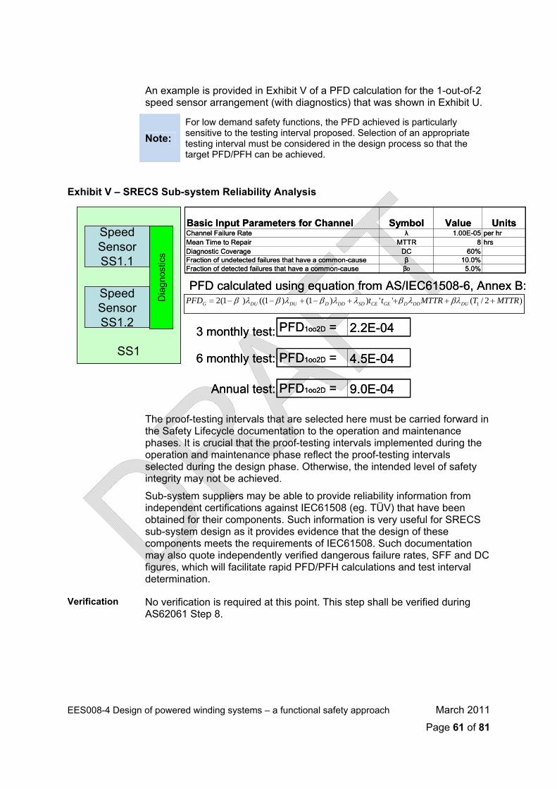
EES008-4 Design of powered winding systems – a functional safety approach March 2011
Page 61 of 81
An example is provided in Exhibit V of a PFD calculation for the 1-out-of-2
speed sensor arrangement (with diagnostics) that was shown in Exhibit U.
Note:
For low demand safety functions, the PFD achieved is particularly sensitive to the testing interval proposed. Selection of an appropriate testing interval must be considered in the design process so that the target PFD/PFH can be achieved.
Exhibit V – SRECS Sub-system Reliability Analysis
The proof-testing intervals that are selected here must be carried forward in
the Safety Lifecycle documentation to the operation and maintenance phases. It is crucial that the proof-testing intervals implemented during the operation and maintenance phase reflect the proof-testing intervals selected during the design phase. Otherwise, the intended level of safety integrity may not be achieved.
Sub-system suppliers may be able to provide reliability information from independent certifications against IEC61508 (eg. TÜV) that have been obtained for their components. Such information is very useful for SRECS sub-system design as it provides evidence that the design of these components meets the requirements of IEC61508. Such documentation may also quote independently verified dangerous failure rates, SFF and DC figures, which will facilitate rapid PFD/PFH calculations and test interval determination.
Verification No verification is required at this point. This step shall be verified during AS62061 Step 8.
SS1
SpeedSensorSS1.1
SpeedSensorSS1.2
Dia
gnos
tics
)2/(''))1()1(()1(2 1 MTTRTMTTRttPFD DUDDDGECESDDDDDUDUG ++++−+−−= βλλβλλβλβλβPFD calculated using equation from AS/IEC61508-6, Annex B:
PFD1oo2D = 2.2E-043 monthly test:
Annual test: PFD1oo2D = 9.0E-04
Basic Input Parameters for Channel Symbol Value UnitsChannel Failure Rate λ 1.00E-05 per hrMean Time to Repair MTTR 8 hrsDiagnostic Coverage DC 60%Fraction of undetected failures that have a common-cause β 10.0%Fraction of detected failures that have a common-cause βD 5.0%
6 monthly test: PFD1oo2D = 4.5E-04SS1
SpeedSensorSS1.1
SpeedSensorSS1.2
Dia
gnos
tics
Basic Input Parameters for Channel Symbol Value UnitsChannel Failure Rate λ 1.00E-05 per hrMean Time to Repair MTTR 8 hrsDiagnostic Coverage DC 60%Fraction of undetected failures that have a common-cause β 10.0%Fraction of detected failures that have a common-cause βD 5.0%
SpeedSensorSS1.1
SS1
Dia
gnos
tics
SpeedSensorSS1.2
)2/(''))1()1(()1(2 1 MTTRTMTTRttPFD DUDDDGECESDDDDDUDUG −= β λ − β λ + − β λ + λ +β λ + βλ +
PFD calculated using equation from AS/IEC61508-6, Annex B:
PFD1oo2D = 2.2E-043 monthly test:
Annual test: PFD1oo2D = 9.0E-04
6 monthly test: PFD1oo2D = 4.5E-04
Documentation (for inclusion in the Safety Lifecycle Dossier)
A dossier of documentation associated with the design of each SRECS sub-system is detailed in AS62061 Clause 6.7 and this should be added to the Safety Lifecycle Dossier. The following information should be provided by the designer/s, as applicable:
• Sub-system functional specifications for the functions and interfaces which will be used by the SRCFs,
• Sub-system realisation (actual design drawings, assemblies and component selections),
• Component data sheets, • The results of Factory Acceptance Testing, • Component safety certifications and other certifications, such as
EMI compliance, Ex-ratings etc., • Calculations of Fault Tolerance, Safe Failure Fraction (SFF) and
either PFD or PFH values for each SRECS sub-system, as appropriate to the demand mode.
• Component / module reliability data to support the above calculations, including estimated rates of failure of any failure modes that would cause a dangerous failure of the SRECS sub-systems,
• A statement of the fault exclusions claimed when estimating the fault tolerance and SFF figures,
• Probability of dangerous transmission errors for digital data communication processes, where applicable.
• Constraints due to environmental or operating conditions and the lifetime of the sub-system which should not be exceeded,
• Test and maintenance requirements, • Diagnostic coverage and diagnostic testing interval, • Information to allow the calculation of a Mean Time to Repair
(MTTR),
• System ‘Type’ (A or B – see AS62061 Step4) and SIL claim limit of the sub-system due to architectural constraints,
• Limits on the application of the sub-system,
• The highest SIL that can be claimed by a SRCF which uses the sub-system, on the basis:
o Measures taken against the introduction of systematic faults being during design and implementation of hard ware and software,
o Design features which make the sub-system tolerant against systematic faults,
• Information to enable hardware and software configuration management.
EES008-4 Design of powered winding systems – a functional safety approach March 2011
Page 62 of 81

A S 6 2 0 6 1 S t e p 7 – D e s i g n a n d D e v e l o p D i a g n o s t i c s
AS62061 Steps 6-9 may practically be conducted together.
Objective/s To realise the associated SRECS diagnostic functions that are necessary to fulfil the requirements of the architectural constraints and safety integrity requirements of the allocated function blocks of the SRCFs.
Requirements From AS62061 Clause 6.8 the following must be achieved:
• The diagnostic functions should be considered as separate functions that may have a different structure to the SRCFs and may be performed by:
o The same sub-system which requires the diagnostics (ie. embedded diagnostics in the sensor devices),
o Other sub-systems of the SRECS (eg. PLC-based diagnostics of the sensors),
o Sub-systems of the SRECS not performing the SRCF’s.
• Diagnostics shall also satisfy certain requirements that are also applicable to the SRCFs, namely:
o Requirements for avoidance of systematic failure,
o Requirements for control of systematic failures.
• The probability of dangerous failure of the SRECS diagnostic functions shall be taken into account when estimating the probability of dangerous failure of the SRCFs.
• A clear description of the SRECS diagnostic functions, their failure detection and an analysis of their contribution to the safety integrity of the SRCFs (ie. probability of dangerous failure) shall be provided.
Implementation An iterative design process is suggested for the design of each SRECS sub-system diagnostics. The requirements for the design and development of diagnostics utilised in SRECS sub-systems are covered in AS62061 Clauses 6.8. The requirements for the design and development of software used in SRECS sub-systems are covered by AS62061 Clause 6.11.The key focus of the design of diagnostics must be to maximise the proportion of safe and dangerous failure modes that are detectible, as this will have the following effect upon the safety integrity of the SRECS sub-systems:
• It will increase the Diagnostic Coverage (DC) of the devices / modules utilised in the SRECS sub-system,
• It will increase the Safe Failure Fraction (SFF) of the devices / modules utilised in the SRECS sub-systems, allowing a higher architectural SIL claim limit for a given system type and fault tolerance / redundancy configuration,
EES008-4 Design of powered winding systems – a functional safety approach March 2011
Page 63 of 81

EES008-4 Design of powered winding systems – a functional safety approach March 2011
Page 64 of 81
• It will decrease the proportion of SRECS sub-system failure modes
that are dangerous and undetected, which will reduce the predicted PFH and PFD values of the SRECS sub-systems.
Design of diagnostics should be steered by the FMEDA conducted during AS62061 Step 6. Guidance for the calculation of SFF, PFD and PFH values is provided in AS62061 Clause 67.7 and 6.7.8 and AS61508-6 Annex B and C.
An example of the effect of good diagnostics on safety system design is provided below in Exhibit W. These calculations, which are based upon AS/IEC61508-6 Annex B, show that a single speed sensor with very good diagnostics (ie. ~90.2%) can achieve the same PFD as a redundant pair of speed sensors with no diagnostics.
Exhibit W – SRECS Sub-system Diagnostics
Sub-system suppliers may be able to provide information on diagnostic
coverage from independent certifications against IEC61508 (eg. TÜV) that have been obtained for their components. Such information should be obtained where possible as it may allow the selection of simpler SRECS sub-system architectures.
Verification No verification is required at this point. This step shall be verified during AS62061 Step 8.
Documentation (for inclusion in the Safety Lifecycle Dossier)
• SRECS Diagnostics Concept which apportions diagnostic functions to each of the SRECS sub-systems.
• SRECS Diagnostics Specification for each SRECS sub-system (this may be included with the SRECS sub-system design documentation provided in AS62061 Step 6), including: o Clear description of the diagnostic functions, o Failure modes covered,
SS1
SpeedSensorSS1.1
SpeedSensorSS1.2
Dia
gnos
tics
PFD1oo2D = 2.2E-04
Basic Input Parameters for Channel Symbol Value UnitsChannel Failure Rate λ 1.00E-05 per hrMean Time to Repair MTTR 8 hrsTest Interval T1 2190 hrsFraction of undetected failures that have a common-cause β 10.0%Fraction of detected failures that have a common-cause βD 5.0%
Diagnostic Coverage of 0% : PFD1oo2 = 5.8E-04
Diagnostic Coverage of 60% :
Diagnostic Coverage of 90.2% : PFD1oo2D = 5.6E-05
PFD1oo1D = 5.8E-04Diagnostic Coverage of 90.2% :SS1
SpeedSensorSS1.1
SpeedSensorSS1.2
Dia
gnos
tics
SS1
SpeedSensorSS1.1
SpeedSensorSS1.2
Dia
gnos
tics
PFD1oo2D = 2.2E-04
Basic Input Parameters for Channel Symbol Value UnitsChannel Failure Rate λ 1.00E-05 per hrMean Time to Repair MTTR 8 hrsTest Interval T1 2190 hrsFraction of undetected failures that have a common-cause β 10.0%Fraction of detected failures that have a common-cause βD 5.0%
Diagnostic Coverage of 0% : PFD1oo2 = 5.8E-04
Diagnostic Coverage of 60% :
Diagnostic Coverage of 90.2% : PFD1oo2D = 5.6E-05Diagnostic Coverage of 90.2% : PFD1oo1D = 5.8E-04

o Method of detection of failures,
o Diagnostic coverage expected to be achieved,
o Reaction of the diagnostics upon detection of a failure,
o Probability of failure of the diagnostic function (so that its contribution to the overall safety integrity of the associated SRCFs can be ascertained).
A S 6 2 0 6 1 S t e p 8 – D e t e r m i n e t h e A c h i e v e d S I L f o r e a c h S R C F
AS62061 Steps 6-8 may practically be conducted together.
Objective/s • To determine, via a reliability analysis, that the target failure measures for the allocated SIL for each SRCF have been met by the SRECS.
• To confirm that the architectural constraints applicable to the allocated SIL for each SRCF have been met by the SRECS.
Requirements From AS62061 Clause 6.6.3 (using the information sourced in AS62061 Steps 4, 6 and 7), as follows:
• The SIL that can be achieved by the SRECS shall be considered separately for each SRCF to be performed by the SRECS,
• The probability of dangerous failure of each SRCF shall be calculated and shown to be equal to or less that the target failure value as specified in the Safety Requirements Specification.
• The probability of dangerous failure shall be estimated taking into account the architecture of the SRECS as it relates to the SRCF under consideration and the estimated rate of failure of each SRECS sub-system to perform its allocated function.
• The SIL achieved by the SRECS according to the architectural constraints is to be less than or equal to the lowest SIL claim limit of any SRECS sub-system involved in the performance of the SRCF.
• The SIL achieved by the SRECS is less than or equal to the lowest SIL claim limit of any SRECS sub-system involved in the performance of the SRCF.
Implementation Determination of the achieved SIL of an SRCF provides an excellent opportunity for verification of the design process undertaken during AS62061 Steps 6-7. The Functional Safety Plan developed during AS61508 Step 2 will have included a Verification Plan and this should include an allowance for AS62061 Step 8 to be undertaken as a verification activity. Verification may be carried out iteratively as the design proceeds.
EES008-4 Design of powered winding systems – a functional safety approach March 2011
Page 65 of 81

Verification of the SIL of each SRCF should be carried out by persons will
an appropriate degree of independence and competence. Guidance on the level of competence of verifiers is given in AS61508-1 Annex B, which includes consideration of the following:
• Engineering knowledge appropriate to the application areas, • Engineering knowledge appropriate to the technology, • Safety engineering knowledge appropriate to the technology, • Knowledge of legal and regulatory framework, • Consequences of the failure of the SRECS – the higher the
consequences, the more rigorous should be the assessment of competence,
• SIL target of the SRECS – the higher the SIL, the more rigorous should be the assessment of competence,
• Novelty of the design, procedures or application – the newer or more untried the design, the more rigorous should be the assessment of competence,
• Previous experience and relevant to the specific duties to be performed,
• Relevance of qualifications to the specific duties to be performed.
Guidance on the appropriate level of independence of verifiers is provided in AS61508-1 Clause 8.2.14. Generally, a SIL1 SCRF may be verified by a suitably competent person within the same department who was not involved in the design. SIL2 requires a suitably competent person from a different department who was not involved in the design. SIL3 requires verification by an independent organisation which was not involved in the design.
The verification process, regardless of SIL, must include a confirmation of the following features of each SRCF:
• Satisfaction of the architectural constraints for the applicable SIL for each SRECS sub-system involved in performing the SRCFs.
• Achieving either a total Probability of Failure on Demand (PFD) or Probability of Failure per Hour (PFH) value for each SRCF, as applicable, that complies with the target failure values for the SIL that was allocated to the SCRF and its function blocks.
• Achieving the requirements for avoidance of systematic failures and for the control of systematic failures, for both hardware and software used in the SRECS, per the requirements of AS62061 Clause 6.7.9 and AS61508-2 and AS61508-3.
Exhibit X shows a how the architectural and reliability analysis results that may be presented for a mine winder’s SRCFs such as the Over-speed Protection safety function.
EES008-4 Design of powered winding systems – a functional safety approach March 2011
Page 66 of 81
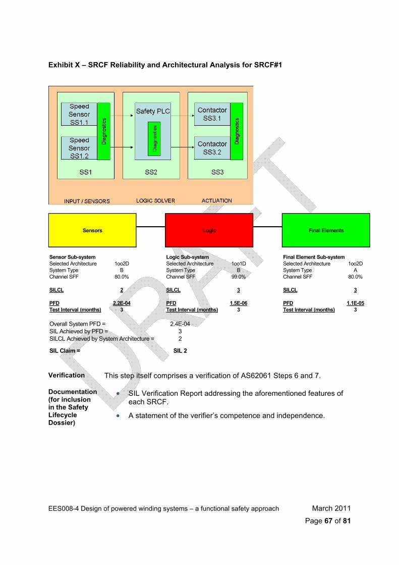
EES008-4 Design of powered winding systems – a functional safety approach March 2011
Page 67 of 81
Exhibit X – SRCF Reliability and Architectural Analysis for SRCF#1
Sensors Logic Final Elements
Sensor Sub-system Logic Sub-system Final Element Sub-systemSelected Architecture 1oo2D Selected Architecture 1oo1D Selected Architecture 1oo2DSystem Type B System Type B System Type AChannel SFF 80.0% Channel SFF 99.0% Channel SFF 80.0%
SILCL 2 SILCL 3 SILCL 3
PFD 2.2E-04 PFD 1.5E-06 PFD 1.1E-05Test Interval (months) 3 Test Interval (months) 3 Test Interval (months) 3
Overall System PFD = 2.4E-04SIL Achieved by PFD = 3SILCL Achieved by System Architecture = 2
SIL Claim = SIL 2 Verification This step itself comprises a verification of AS62061 Steps 6 and 7.
Documentation (for inclusion in the Safety Lifecycle Dossier)
• SIL Verification Report addressing the aforementioned features of each SRCF.
• A statement of the verifier’s competence and independence.

A S 6 2 0 6 1 S t e p 9 – D o c u m e n t t h e S R E C S A r c h i t e c t u r e
Objective/s Provide a comprehensive overview of all SRCF’s associated with the EUC, their contributing function blocks, and the corresponding implementing sub-systems within the SRECS.
Requirements From AS62061 Clause 6.6.2.1.5 as follows:
• The architecture of the SRCFs function blocks and SRECS sub-systems shall be documented describing the overall allocations and the functional and physical inter-relationships.
Implementation This step is more important for complex EUCs that require numerous SRCFs to be implemented via many function blocks and SRECS sub-systems. The following diagram in Exhibit Y shows how this requirement may be achieved using the example of a mine winder SRECS.
Exhibit Y – SRECS Architecture
EES008-4 Design of powered winding systems – a functional safety approach March 2011
Page 68 of 81
Verification No verification is required at this point.
Documentation (for inclusion in the Safety Lifecycle Dossier)
Overall SRECS Architecture Diagram (as shown above).
A S 6 2 0 6 1 S t e p 1 0 – I m p l e m e n t t h e D e s i g n e d S R E C S
This is point at which the application of the AS62061 lifecycle ends for machinery applications so there is a transition from AS62061 requirements to AS61508 requirements at this point.
Objective/s To integrate, test, install and commission the SRECS so that it is ready for intended use and for safety validation.
Requirements From AS62061 Clause 6.12 and 6.13 as follows:
• The SRECS shall be implemented according to the specified design,
• Testing shall be carried out to verify that modules behave and interact correctly to perform their intended function and not perform unintended functions,
• The integration of application software shall include tests specified during the design and development to ensure its compatibility with the SRECS hardware and its embedded software platform,
• Testing to reveal faults and avoid failures due to integration of hardware and software shall be carried out,
• The SRECS shall be installed in accordance with the functional Safety Plan for the final safety validation,
• The information and results acquired shall be documented and maintained throughout the overall safety lifecycle.
Implementation Implementation of the SRECS should follow established management processes as far as possible for the organisation in question, providing that the essential requirements are being met. Any special requirements for functional safety that are not achieved by the standard operation and maintenance management processes should be dealt with in the Functional Safety Plan.
Verification No verification is required at this point. This step shall be verified during the overall safety validation during AS61508 Step 13.
EES008-4 Design of powered winding systems – a functional safety approach March 2011
Page 69 of 81

Documentation (for inclusion in the Safety Lifecycle Dossier)
• Results of SRECS Sub-system Hardware Testing, • Documentation of SRECS Hardware Integration Testing, • Results of Application Software Module Testing, • Results of Application Software Integration Testing, • Documentation of SRECS Installation and Commissioning.
A S 6 1 5 0 8 S t e p 1 3 – O v e r a l l S a f e t y V a l i d a t i o n
This is point at which the application of the AS62061 lifecycle ends for machinery applications so there is a transition from AS62061 requirements to AS61508 requirements at this point. For overall validation of the safety lifecycle, the requirements of AS61508 Step 13 are used.
Objective/s To validate that the SRECS meets the specification for the overall safety requirements in terms of the overall safety functions requirements and the overall safety integrity requirements, taking into account the safety requirements allocation for the SRECS developed according to AS61508 Step 4 and AS62061 Steps 1- 4.
Note:
Validation is different in nature to verification. AS61508-4 describes the difference. Validation – confirmation by examination and provision of objective evidence that the particular requirements for the specific intended use are fulfilled. Verification – confirmation by examination and provision of objective evidence that the requirements have been fulfilled.
Requirements From AS61508-1 Clause 7.14 (using the information sourced in AS61508 Step 4 and AS62061 Steps 1- 4), as follows:
• Validation shall be carried out in accordance with the overall Validation Plan that should have been prepared in accordance with the Functional Safety Plan, developed during AS61508 Step 2,
• All equipment used for quantitative measurements as part of the validation activities shall be calibrated against a specification traceable to a national standard or to a vendor specification,
• When discrepancies occur between actual and expected results, the analysis made and the decisions taken on whether to continue the validation or issue a change request and return to an earlier part of the validation shall be documented.
Implementation Validation should be carried out in accordance with the Validation Plan contained within the Functional Safety Plan which was compiled in AS61508 Step 2.
EES008-4 Design of powered winding systems – a functional safety approach March 2011
Page 70 of 81
EES008-4 Design of powered winding systems – a functional safety approach March 2011
Page 71 of 81
Whilst functional safety validation is covered in principle by AS61508,
AS62061 also provides guidance for machinery sector applications in Clause 8 of that standard.
This step will be critical for the successful registration of plant. At the conclusion of this step there must be sign-off by the designer and the EUC owner that the SRECS, comprising all of its sub-systems and hardware and software, meets all of the functional and safety integrity requirements for all of the SRCFs allocated to it, as specified in the Safety Requirements Specification produced in AS62061 Step 4. This step also ensures that the SRECS is installed and operating correctly, and that all the necessary procedures and arrangements are in place to ensure the SIL allocated to each SRCF can be maintained through-life.
Therefore, the following aspects should be determined and documented before validation of the SRECS, per Exhibit G.
(Exhibit G – Validation Plan)
Verification This step itself comprises an overall validation of the installed SRECS
before hand-over to the EUC owner.
Documentation (for inclusion in the Safety Lifecycle Dossier)
• Documentation of the SRECS Validation shall include: • Documentation of the validation activities, • The version of the specification of the overall safety requirements
being used, • The safety function being validated (by test or analysis), • Tools and equipment used with calibration data, • The results of the validation activities, including recorded
discrepancies between expected and actual results, • Configuration identification of the item under test, the procedures
applied and the test environment, • A statement of the valuator’s competence and independence.

A S 6 1 5 0 8 S t e p 1 4 – O p e r a t i o n a n d M a i n t e n a n c e
Specific requirements are provided in AS61508-1 for this step, however AS62061 also provides some guidance for application to the machinery sector. This section blends both sets of requirements.
Objective/s • To operate, maintain and repair the SRECS in order that the required level of functional safety is maintained through-life.
• Information on the SRECS shall be provided to enable the user to develop procedures to ensure that the required functional safety of the SRECS is maintained during use and maintenance of the EUC.
Requirements From AS61508-1 Clause 7.15:
• The following shall be implemented: o A plan for maintaining the SRECS, o Operation, maintenance and repair procedures for the SRECs, o Operation and maintenance procedures for software.
• The following actions shall occur: o Implementation of procedures, o Compliance to maintenance schedules, o Maintenance of documentation, o Periodic functional safety audits, o Documenting modifications that are made to the SRECS (see
Step 15 for details). • The information and results acquired shall be documented and
maintained throughout the overall safety lifecycle.
Implementation This is the potentially the longest step within the functional safety lifecycle. During this step there will potentially be changes in staffing, management and ownership of the EUC. Technology will change, as will the availability of EUC, EUC control system and SRECS spare parts for maintenance and repair. Changes may also be made to the design of the EUC or its control system, which may also necessitate changes to the SRECS. Operations and maintenance practices may change, as may staff experience and knowledge levels.
Functional safety during this step of the lifecycle must be seen as a ‘legacy’ process, whereby the verified requirements arising from all the previous steps in the lifecycle continue to be satisfied and the validated SRECS performance continues to be attained. This approach is very much aligned with the ‘Treat Risk’, ‘Monitor / Review’ and ‘Communicate / Consult’ steps of the MDG1010 and AS/NZS4360 risk management processes.
EES008-4 Design of powered winding systems – a functional safety approach March 2011
Page 72 of 81

All of the procedures, training and arrangements necessary to ensure that
the functional and safety integrity requirements of the SRECS will continue to be met must be documented, communicated, implemented, monitored, regularly reviewed and continuously improved. Compliance to procedures, maintenance schedules and the effective management of the configuration of the EUC, its control system and the SRECS will be paramount to the continued achievement of the functional and safety integrity requirements of the EUC, its control system and the SRECS.
Operation and maintenance activities for a winder, its control system and its SRECS should follow established management processes as far as possible for the mine in question, providing that the essential requirements listed above are being met. Any special requirements for functional safety that are not achieved by the standard operation and maintenance management processes should be dealt with in the Functional Safety Plan.
Exhibit Z shows a suggested flow-chart for activities to be undertaken on the winder SRECS during this step, derived from AS61508-1 Figures 7 and 8. This flow-chart is primarily focussed on the resolution of detected and undetected faults in the winder SRECS through-out its life, in order to assure its reliability. Importantly, the actual reliability performance of the SRECS is able to be determined and compared with earlier predictions so that prompt action make be taken to alleviate any discrepancy. The flow-chart also takes account of maintenance compliance to the specified SRECS proof-testing intervals, as this is usually a key determinant of SRECS reliability.
If the specified PFH / PFD targets are not achieved in operation, or the actual SRECS demand rate increases beyond that expected, there are potential ramifications for the SRECS. These factors may impact on the ability of the installed risk controls to achieve the Necessary Risk Reduction for a tolerable level of risk. So, there may be a need for system modifications, which may include the EUC, EUC control system, SRECS or the other non-SRECS risk controls. This event leads to the initiation of AS61508 Step 15.
EES008-4 Design of powered winding systems – a functional safety approach March 2011
Page 73 of 81
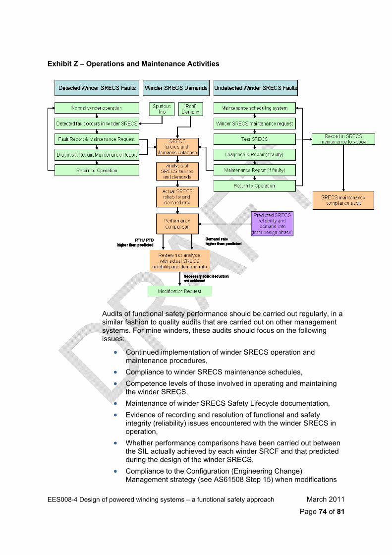
EES008-4 Design of powered winding systems – a functional safety approach March 2011
Page 74 of 81
Exhibit Z – Operations and Maintenance Activities
Audits of functional safety performance should be carried out regularly, in a
similar fashion to quality audits that are carried out on other management systems. For mine winders, these audits should focus on the following issues:
• Continued implementation of winder SRECS operation and maintenance procedures,
• Compliance to winder SRECS maintenance schedules, • Competence levels of those involved in operating and maintaining
the winder SRECS, • Maintenance of winder SRECS Safety Lifecycle documentation, • Evidence of recording and resolution of functional and safety
integrity (reliability) issues encountered with the winder SRECS in operation,
• Whether performance comparisons have been carried out between the SIL actually achieved by each winder SRCF and that predicted during the design of the winder SRECS,
• Compliance to the Configuration (Engineering Change) Management strategy (see AS61508 Step 15) when modifications

EES008-4 Design of powered winding systems – a functional safety approach March 2011
Page 75 of 81
its are carried out on the winder, winder control system or SRECS. and retrof
There is a requirement for re-registration of plant every five (5) years. This
is an appropriate time to perform a functional safety audit, however it is strongly recommended that functional safety audits should be carried out more often than once every five years.
Verification Auditing against the requirements for operation and maintenance of the SRECS against its functional safety requirements should be carried out at regular intervals and corrective action taken, where appropriate.
Documentation (for inclusion in the Safety Lifecycle Dossier)
This following information for installation, use and maintenance should be provided by the SRECS designer in accordance with AS62061 Clause 7:
• Comprehensive description of the SRECS equipment, installation and mounting,
• A statement of intended use and any measures required to prevent misuse,
• Information about the physical environment (ie. lighting, vibration, noise, atmosphere) where appropriate,
• Overview block diagram, • Circuit diagrams, • Proof test interval, • Expected useable lifetime, • A description of the interaction between the SRECS and the EUC
control system, • A description of safeguarding and of the means provided to
maintain safety where it is necessary to suspend the SRCF’s (eg. for software upgrades, maintenance etc.)
• Programming information, where appropriate, • A description of the maintenance requirements applicable to the
SRECS, including: o A log for recording maintenance history of the machine, o Routine actions necessary to maintain functional safety (eg.
fixed time replacement of components), o Maintenance procedures to be followed when faults or failures
occur in the SRECS, including – fault diagnosis and repair, confirmation of correct operation post-repair, maintenance recording requirements,
o Tools and equipment necessary for maintenance and the procedures for maintaining the tools and equipment,
o A specification for periodic testing, preventive maintenance and corrective maintenance.
EES008-4 Design of powered winding systems – a functional safety approach March 2011
Page 76 of 81
In addition, the following information generated during this step should be
compiled in the Safety Lifecycle Dossier:
• Operation & Maintenance manuals, • Register of engineering changes made to hardware and software, • Register of changes to technical documentation, • The results of any functional safety audits, • SRECS failures and incidents, • Root Cause Analysis investigations into failures and incidents, • Evidence of regular checking of maintenance compliance, • Evidence of compliance to the Functional Safety Plan, Configuration
Management Plan and other associated plans and procedures via Quality Management audits.
A S 6 1 5 0 8 S t e p 1 5 – M o d i f i c a t i o n a n d R e t r o f i t
Objective/s To ensure that the functional safety of the SRECS is appropriate, both during and after a modification or retrofit.
Requirements From AS61508-1 Clause 7.16:
• A configuration management plan should have been implemented in accordance with the Functional Safety Plan developed during AS61508 Step 2,
• The modification or retrofit shall only be initiated by the issue of an authorised request, under procedures provided in the Functional Safety Plan, which shall be dependent on the results of an impact analysis,
• The reason for the modification shall be documented as well as the hazards affected and the details of the proposed change,
• An impact analysis of the modification shall be analysed to establish the effect on functional safety of the SRECS,
• The assessment shall include a hazard and risk analysis sufficient to determine the necessary breadth and depth of subsequent activities,
• All accepted modifications that have an effect on the SRECS shall initiate a return to an appropriate design phase for hardware and/or software. All subsequent phases shall then be carried out,
• A complete action plan shall be prepared and documented before carrying out any modifications,
• The information and results acquired shall be documented and maintained throughout the overall safety lifecycle.
EES008-4 Design of powered winding systems – a functional safety approach March 2011
Page 77 of 81
Implementation Modification and retrofit activities for a SRECS as far as is possible should
follow established engineering change management processes for the organisation in question, providing that the essential requirements are being met. Any special requirements for functional safety that are not achieved by the standard engineering change management process should be dealt with in the Functional Safety Plan.
Verification Verification of the modified SRECS shall be conducted to ensure that the required safety integrity is still achieved after the modification has been carried out.
Documentation (for inclusion in the Safety Lifecycle Dossier)
Documentation for SRECS configuration management collected during this step in accordance with AS62061 should include:
• Configuration Management Plan, • Engineering Change Proposals, • Details of the analysis of the changes, • Documentation generated by the return to the appropriate design
phase and all subsequent steps, • Modification Action Plans, • Verification report of the modifications.
A S 6 1 5 0 8 S t e p 1 6 – D e c o m m i s s i o n i n g a n d D i s p o s a l
Objective/s To ensure that the functional safety of the SRECS is appropriate for the circumstances during and after the activities of decommissioning or disposal of the EUC.
Requirements From AS61508-1 Clause 7.17 as follows:
• Before decommissioning / disposal an impact analysis shall be carried out and shall include an assessment of the impact of the proposed activity on the functional safety of the SRECS associated with the EUC,
• The impact analysis shall also consider adjacent EUC’s and the impact on their SRECS,
• The assessment shall include a hazard and risk analysis sufficient to determine the necessary breadth and depth of subsequent activities,
• Decommissioning / disposal shall only be initiated by the issue of an authorised request, which shall be dependent on the results of the impact analysis,
• Before decommissioning / disposal takes place a plan shall be prepared which shall include procedures for the closing down of the SRECS and its dismantling,
EES008-4 Design of powered winding systems – a functional safety approach March 2011
Page 78 of 81
• If decommissioning / disposal has an impact on the functional
safety of the SRECS, it shall initiate a return to the appropriate lifecycle phase in order to address those inadequacies identified,
• The information and results acquired shall be documented and maintained throughout the overall safety lifecycle.
Implementation Decommissioning and disposal may generally be practically treated in the same way as a modification / retrofit phase, recognising the special nature of the decommissioning / disposal activity.
Verification Verification requirements should be determined on the basis of:
• The expected impact of the decommissioning / disposal activity on the functional safety achieved by the SRECS,
• If a return to earlier lifecycle steps is necessary.
Documentation (for inclusion in the Safety Lifecycle Dossier)
Documentation of this step should include:
• Decommissioning / Disposal Request, • Impact analysis of decommissioning / disposal upon the functional
safety of the SRECS,
• Documentation generated by the return to the appropriate design phase and all subsequent steps,
• Decommissioning Plans.
EES008-4 Design of powered winding systems – a functional safety approach March 2011
Page 79 of 81

4. Appendices
F e e d b a c k S h e e t Your comment on this Technical Reference is essential for its review and improvement.
Please make a copy of this Feedback Sheet and send your comments to: The Senior Inspector of Electrical Engineering Mine Safety Operations Industry and Investment NSW PO Box 344 Hunter Region Mail Centre NSW 2310 Phone: (02) 4931 6641 Fax: (02) 4931 6790
How did you use (or intend to use) this Technical Reference?
What did you find most useful about the Technical Reference?
What did you find least useful about the Technical Reference?
Do you have any suggestions to improve the Technical Reference?
Thank you for completing and returning the Feedback Sheet.
EES008-4 Design of powered winding systems – a functional safety approach March 2011
Page 80 of 81

EES008-4 Design of powered winding systems – a functional safety approach March 2011
Page 81 of 81
I & I N S W C o n t a c t d e t a i l s I&I NSW offices located in coal mining regions.
North East Area South East Area
Maitland Lithgow
516 High Street
Maitland NSW 2320
PO Box 344
Hunter Regional Mail Centre NSW 2310
Phone: (02) 4931 6666 Fax: (02) 4931 6790
Suite 1, 1st Floor,
184 Mort Street
Lithgow NSW 2790
Phone: (02) 6350 7888 Fax: (02) 6352 3876
Singleton Wollongong
Level 1, 1 Civic Avenue
Singleton NSW 2330
PO Box 51
Singleton NSW 2330
Phone: 02 6572 1899 Fax: 02 6572 1201
Level 3, Block F,
84 Crown Street
Wollongong NSW 2500
PO Box 674
Wollongong NSW 2520
Phone: (02) 4222 8333 Fax: (02) 4226 3851