Part 4 Ropes - technical reference guide powered winding ...
69
TECHNICAL REFERENCE GUIDE POWERED WINDING SYSTEMS Part 4: Ropes
Transcript of Part 4 Ropes - technical reference guide powered winding ...

TECHNICAL REFERENCE GUIDE
POWERED WINDING SYSTEMS Part 4: Ropes

Technical reference guide: Powered winding systems
Part 4: Ropes
1
Document control
Published by NSW Resources Regulator
Title: Technical reference guide: Powered winding systems – Part 4: Ropes (replaces draft MDG 33.7)
First published: January 2020
Authorised by: Chief Inspector, NSW Resources Regulator
CM9 reference: DOC19/508956
AMENDMENT SCHEDULE
Date Version Amendment
January 2020 1 Original version
Supersedes MDG 33 (1998), MDG 12 (1992), MDG 26 (1999) and MDG 2005 (2003). Reflects 2020 NSW WHS legislative framework. Developed in consideration of current Australian standards, international standards, the EES008 series and industry feedback from the 2011 consultation process for draft MDG 33 (1-7) series.
© State of New South Wales through Department of Planning, Industry and Environment 2020. You may copy, distribute, display, download and otherwise freely deal with this publication for any purpose, provided that you attribute the Department of Planning, Industry and Environment as the owner. However, you must obtain permission if you wish to charge others for access to the publication (other than at cost); include the publication in advertising or a product for sale; modify the publication; or republish the publication on a website. You may freely link to the publication on a departmental website.
Disclaimer: The information contained in this publication is based on knowledge and understanding at the time of writing (September 2019) and may not be accurate, current or complete. The State of New South Wales (including the NSW Department of Planning, Industry and Environment), the author and the publisher take no responsibility, and will accept no liability, for the accuracy, currency, reliability or correctness of any information included in the document (including material provided by third parties). Readers should make their own inquiries and rely on their own advice when making decisions related to material contained in this publication.
DOC19/508956

Technical reference guide: Powered winding systems
Part 4: Ropes
2
Contents 1. Introduction ............................................................................................................................................... 5
1.1. Scope and application ......................................................................................................................... 5
1.2. Abbreviations and definitions ............................................................................................................. 6
1.3. References ........................................................................................................................................... 6
2. Rope design and construction ................................................................................................................... 7
2.1. Manufacturer’s certificate .................................................................................................................. 7
2.2. Rope torque and stability .................................................................................................................... 7
2.3. Rope lubrication and corrosion protection ......................................................................................... 8
2.4. Drift winder ropes ............................................................................................................................... 9
Rope factor of safety – drift winders ......................................................................................... 12
2.5. Vertical shaft winder ropes (drum, friction, shaft sinking and emergency winders) ....................... 13
General ....................................................................................................................................... 13
Rope factors of safety – vertical shaft winders .......................................................................... 14
Vertical shaft drum winder rope installation ............................................................................. 17
Guide/s and rubbing ropes ......................................................................................................... 17
3. Testing ...................................................................................................................................................... 24
3.1. Testing authority ............................................................................................................................... 24
3.2. General .............................................................................................................................................. 24
3.3. NDT equipment ................................................................................................................................. 25
3.4. Friction winder rope testing requirements ....................................................................................... 26
Frequency of NDT ....................................................................................................................... 26
Destructive testing frequency .................................................................................................... 26
3.5. Drum winder haulage rope testing requirements ............................................................................ 26
3.6. Further recommended tests ............................................................................................................. 27
Frequency of NDT ....................................................................................................................... 27
Reference values of new rope .................................................................................................... 27
Increased frequency of NDT ....................................................................................................... 27

Technical reference guide: Powered winding systems
Part 4: Ropes
3
Guide and rubbing ropes ............................................................................................................ 28
X-ray testing of areas not suitable for NDT ................................................................................ 30
4. Examination ............................................................................................................................................. 31
4.1. General requirements ....................................................................................................................... 31
4.2. Guide rope inspection and rotation .................................................................................................. 32
4.3. Visual examinations – guidance notes .............................................................................................. 32
4.4. Records of visual examinations ......................................................................................................... 33
4.5. Wire rope diameter measurement ................................................................................................... 34
4.6. Corrosion ........................................................................................................................................... 35
4.7. Non-destructive tests and examinations (NDT and NDE) – guidance notes .................................... 35
Length of wire rope to be NDT examined .................................................................................. 35
Limitations of NDT ...................................................................................................................... 36
Records of NDT ........................................................................................................................... 36
Actions following a NDT examination ........................................................................................ 38
4.8. Further guidance notes ..................................................................................................................... 38
5. Discard criteria ......................................................................................................................................... 39
5.1. General .............................................................................................................................................. 39
5.2. Requirements .................................................................................................................................... 39
5.3. Further discard information .............................................................................................................. 42
General ....................................................................................................................................... 42
Fatigue fractures ........................................................................................................................ 42
Surface embrittlement ............................................................................................................... 42
Further resources ....................................................................................................................... 43
6. Records .................................................................................................................................................... 44
Appendices .................................................................................................................................................. 45
Appendix A – References ......................................................................................................................... 45
Relevant Australian Standards ............................................................................................................. 45
International standards ........................................................................................................................ 49
Appendix B – Example: Effect of external wear on rope strength .......................................................... 50

Technical reference guide: Powered winding systems
Part 4: Ropes
4
Appendix C – Comparison between loss of metallic area and strength as measured by non-destructive and destructive testing ............................................................................................................................ 51
Appendix D – Rope life predictions based on correlations between non-destructive and destructive testing methods ....................................................................................................................................... 53
Appendix E - Graphs showing area loss and local faults various rope installations ................................ 54
Appendix F - Diagrams of winding ropes examined by non-destructive testing ..................................... 60
Appendix G – Limitations of NDT ............................................................................................................. 67
Technical reference guide: Powered winding systems
Part 4: Ropes
5
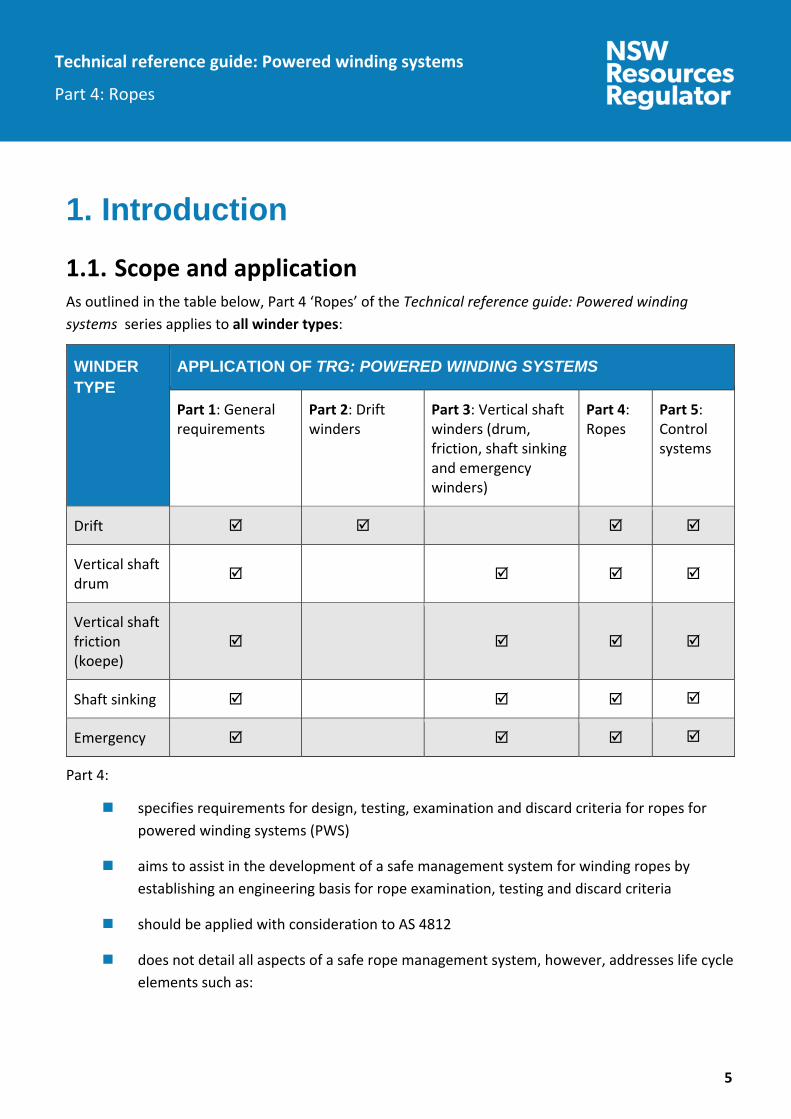
1. Introduction 1.1. Scope and application As outlined in the table below, Part 4 ‘Ropes’ of the Technical reference guide: Powered winding systems series applies to all winder types:
WINDER TYPE
APPLICATION OF TRG: POWERED WINDING SYSTEMS
Part 1: General requirements
Part 2: Drift winders
Part 3: Vertical shaft winders (drum, friction, shaft sinking and emergency winders)
Part 4: Ropes
Part 5: Control systems
Drift
Vertical shaft drum
Vertical shaft friction (koepe)
Shaft sinking
Emergency
Part 4:
specifies requirements for design, testing, examination and discard criteria for ropes for powered winding systems (PWS)
aims to assist in the development of a safe management system for winding ropes by establishing an engineering basis for rope examination, testing and discard criteria
should be applied with consideration to AS 4812
does not detail all aspects of a safe rope management system, however, addresses life cycle elements such as:

Technical reference guide: Powered winding systems
Part 4: Ropes
6
the competence of people to identify defects and assess the cumulative effects of the various contributions to rope deterioration.
a consistent, staged, conservative and documented approach to ensure rope deterioration does not result in the use of ropes without an adequate factor of safety.
the considerations needed to cover specific site conditions.
altering, maintaining or repairing PWS.
Should be used by designers, manufacturers, owners and end users with consideration to:
designing new PWS
verifying new PWS
applying for design registration of PWS
altering existing PWS
carrying out five yearly audits of PWS
reviewing PWS designs following an incident
altering, maintaining or repairing PWS.
In addition to Part 4, appropriate risk management technique and risk assessment process should be used to ensure the safe operation of wire ropes including development of the rope maintenance strategy required for that particular application.
1.2. Abbreviations and definitions For the purposes of this guide, the abbreviations and definitions in Technical reference guide: Powered winding systems – part 1: General requirements apply. 1.3. References Refer to the Appendix for a list of:
Australian and international Standards referenced in this series
All standards referred to in this series relate to the 2019 revision of the standard, as amended from time to time.

Technical reference guide: Powered winding systems
Part 4: Ropes
7
2. Rope design and construction 2.1. Manufacturer’s certificate All new rope must not be used unless the mine holds a manufacturer’s certificate containing the following for the rope:
manufacturer
date of manufacture
diameter
circumference
actual and minimum breaking force
length
mass per metre.
2.2. Rope torque and stability Rope torque factors should be provided and considered wherever there is likelihood of rope torque generation within itself as a result of applied loads during use. This can occur on all winder types.
To calculate the torque value for a particular rope size, multiply the nominal rope diameter by the torque factor.
Example 1:
For 20 mm dia. with torque factor 1.8%:
Torque value = torque factor x rope dia = 1.8% x 20 mm = 0.36 mm
To calculate the torque generated in this rope when subjected to a tensile load, multiply the load by the torque value and combine the units.

Technical reference guide: Powered winding systems
Part 4: Ropes
8
Example 2:
For 20 mm dia. at 75kN tensile load:
Torque generated = torque value x load = 0.36 x 75 = 27Nm
A used rope should not be installed and used unless it can be proven through non-destructive testing (NDT), destructive testing and a written report from a person competent in the design, selection, testing and maintenance of winding ropes that it is safe to use.
Ropes must be attached to conveyances with attachments complying with AS 3637.3.
When attaching the winding rope to the winder drum:
a minimum of three complete dead coils must be retained on the drum at all times
the rope must be anchored to the drum with a suitable clamping device or system. The factor of safety of the clamping device or system must be not less than the rope factor of safety. Spare rope stored on the drum must not be considered as reducing the load on the anchorage.
Sufficient allowance on the total length of winding rope must be made for cutting rope samples for destructive testing and for rope removal subsequent to any damages and defects over its operating life. Consider cross over coil damages and possible needs to end for end ropes, crop drum end of rope etc.
In all cases, the rope construction for the particular application should be referred to the rope manufacturer or their local representative for final recommendation.
PWS operating depths greater than 1000 metres must be provided with detailed industry technical supportive evidence and rationale for all proposed ropes including sizes, specifications and factors of safety.
2.3. Rope lubrication and corrosion protection A wire rope needs lubrication both during manufacture and throughout its working life. It also often needs a preservative, and the grease and oil used serves both of these purposes.
Once the rope has been made, it is extremely difficult to lubricate the interior. Therefore, it is important that:
the lubrication or greasing carried out during manufacture is discussed
the environment and operating conditions are understood, and

Technical reference guide: Powered winding systems
Part 4: Ropes
9
appropriate lubrication is carried out at the manufacturing stage.
Rope wear can and should be reduced to a minimum by using anti-wear materials for guide slippers and other rubbing components within the PWS.
Effective corrosion protection via ongoing lubrication is paramount to extend the life of the rope.
Corrosion can be kept to a minimum by efficient lubrication. The most susceptible being the fixing points at top and bottom.
The use of galvanised wires should be considered where possible to overcome corrosion problems.
Using lubricating tapes at fixing joints to seal out moisture is advantageous, however it should be periodically replaced and checked that there is no entrapment of moisture causing corrosion. This should be done in conjunction with the rope examinations in this area.
Rope lubrication systems should be nominated and provided by the rope designer and manufacturer or their representative. In pre-existing installations, a competent person should be involved with all of the selection processes involving lubrication and the rope.
Permanent installations should provide the lubricator adjacent to the head sheave wheel. Sections of the rope that cannot be lubricated with these permanent lubricators should be identified and hand lubricated as required.
Where corrosion in a shaft is considered to be a problem, the use of half-locked coil ropes have advantages in that the resistance to corrosion is greater since the clearances where moisture can penetrate are smaller.
Consideration should be given to the most susceptible areas such as water migration from gravity and air flows to lower extremities or ropes and their attachments such as guide and tail ropes.
2.4. Drift winder ropes Drift haulage rope construction should be preformed triangular (flattened) strand rope, right hand, langs lay, of grade 1770 MPa wire. Other variations specified must be shown considered and acceptable by a competent person or accredited authority for such a specialised undertaking.
To maintain correct scrolling of the rope for automatic drift haulages, a maximum of three layers of rope must be used.
When attaching the winding rope to the winder drum, the rope must be anchored to the drum with a suitable clamping device or system. The factor of safety of the clamping device or system must be not less than the rope factor of safety. Spare rope stored on the drum must not be considered as reducing the load on the anchorage.

Technical reference guide: Powered winding systems
Part 4: Ropes
10
Sufficient allowance on the total length of winding rope must be made for cutting rope samples for destructive testing and for rope removal subsequent to any damages and defects over its operating life.
The method of attaching the conveyances to the rope for drift haulages must be either with a white metal or resin-filled rope socket and pin, or a precast, fluted, white metal or resin plug and tail-type socket in accordance with AS 3637.3.
Rope inspections and capping changes should be carried out in accordance with AS 4812.
The design of attachments between the control car and the haulage rope must be in accordance with:
AS/NZS 3785.8
AS 3637.1
AS 3637.3
AS 3637.4
AS 3751.
Safety chains must be designed in accordance with the design criteria of AS 3751 and be fitted between:
each conveyance
the haulage rope and the control car.
A rope lubricator should be provided to externally lubricate the rope. The lubricator should be adjacent to the headsheave wheel. Sections of the rope that cannot be lubricated with the lubricator should be hand lubricated as required. The lubrication used should be specified by the rope manufacturer or suitably qualified people.
For a new rope, or after any recapping of the rope, and before winding with people, the haulage must make at least five winds with a load equivalent to the maximum load, or such equivalent load applied, followed by examination for any visible defects and/or deterioration of the connection.

Technical reference guide: Powered winding systems
Part 4: Ropes
11
Figure 1 Typical drift winding ropes – Right hand langs lay
Figure 2 Rope socket bridle and safety chains (for a drift winder)

Technical reference guide: Powered winding systems
Part 4: Ropes
12
Figure 3 Couplings, drawbar and safety chains (for a drift winder)
Rope factor of safety – drift winders The rope breaking force used for calculating the rope factor of safety for the winding installation must be the lesser of either the minimum breaking force for the rope when new or the actual breaking force as tested.
This is divided by the maximum load to be raised or lowered by the rope plus the total mass of the rope acting as load due to gravity when fully let out.
The following factors of safety for drift drum winder ropes must be used:
2.4.1.1. Transport of personnel Ropes, when newly installed must have a factor of safety of not less than 10.
The rope should be discarded when:
the factor of safety falls below 8 via test, or
one of the conditions in clause 5.2 ‘Requirements’ is met.

Technical reference guide: Powered winding systems
Part 4: Ropes
13
2.4.1.2. Transport of other-than-people Ropes, when newly installed must have a factor of safety of not less than 8.
The rope should be discarded when:
there is a loss of breaking strength of greater than 10% of the actual new rope breaking strength
Rope deterioration significantly accelerates as 10% of loss of strength due to wear is approached.
the factor of safety falls below 6, or
one of the conditions in clause 5.2 ‘Requirements’ is met.
The above does not allow for any person riding with the load.
2.5. Vertical shaft winder ropes (drum, friction, shaft sinking and emergency winders)
General For design purposes, selection of rope diameters and strengths should be consistent with recommendations set out in AS 3569. The final selection and recommendation should be made in co-operation with the wire rope manufacturer.
For automatic vertical shaft drum winders, a maximum of five layers of rope on the drum must be used to maintain correct scrolling of the rope.
All rope attachments must comply with AS 3637.3.
Allow for adequate access to working platforms to enable the safe non-destructive examination of winding ropes. Access should be such as to allow maximum coverage of the rope.
The rope construction should be based on the type of conveyance guides.
Technical reference guide: Powered winding systems
Part 4: Ropes
14
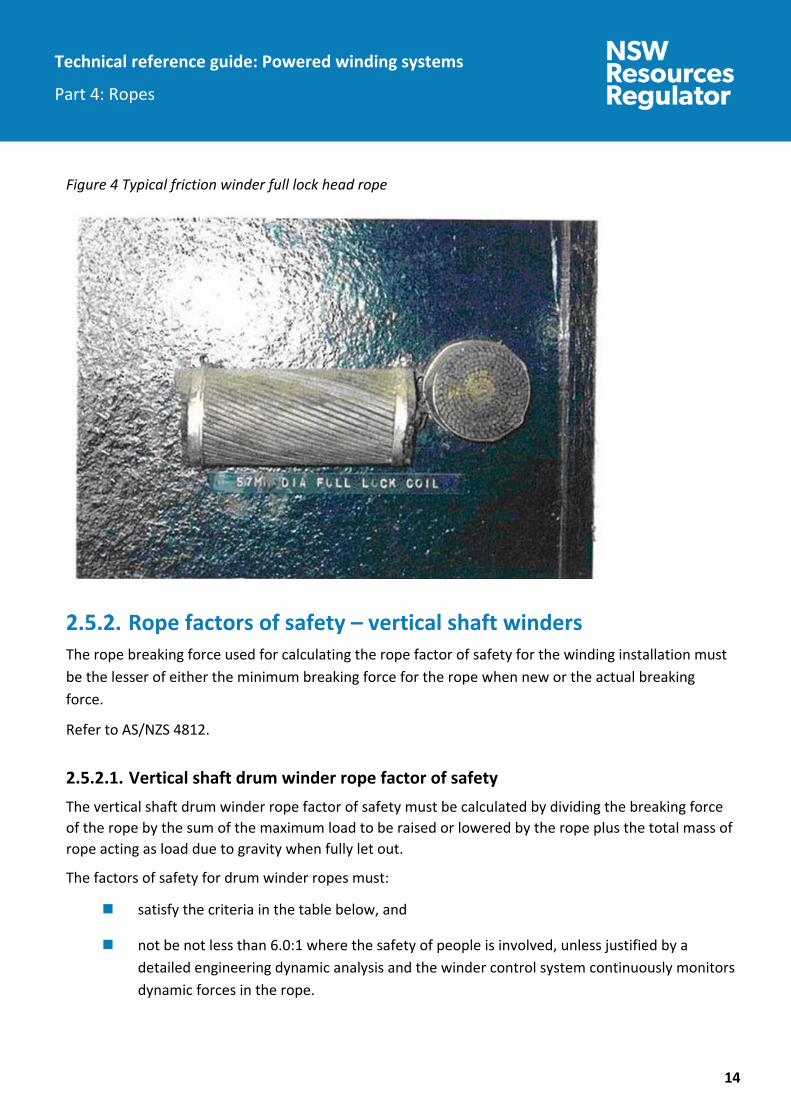
Figure 4 Typical friction winder full lock head rope
Rope factors of safety – vertical shaft winders The rope breaking force used for calculating the rope factor of safety for the winding installation must be the lesser of either the minimum breaking force for the rope when new or the actual breaking force.
Refer to AS/NZS 4812.
2.5.2.1. Vertical shaft drum winder rope factor of safety The vertical shaft drum winder rope factor of safety must be calculated by dividing the breaking force of the rope by the sum of the maximum load to be raised or lowered by the rope plus the total mass of rope acting as load due to gravity when fully let out.
The factors of safety for drum winder ropes must:
satisfy the criteria in the table below, and
not be not less than 6.0:1 where the safety of people is involved, unless justified by a detailed engineering dynamic analysis and the winder control system continuously monitors dynamic forces in the rope.

Technical reference guide: Powered winding systems
Part 4: Ropes
15
CIRCUMSTANCE FACTOR OF SAFETY
Transporting people, or where the safety of people is involved
≥ 7.5 – 0.001L to a minimum FOS of 6.0:1
Transporting of rock or materials, where the safety of people is not involved
≥ 5.5 – 0.0003L
For ropes raising and lowering a shaft sinking stage
≥ 6.0
L is depth of wind in metres
2.5.2.2. Friction winder head rope factor of safety The friction winder head rope factor of safety can be calculated by using either:
the vertical shaft drum winder rope factor calculations (refer clause 2.5.2.1 ‘Vertical shaft drum winder rope factor of safety’).
If these are used, they must be subject to the designer recommendation and in conjunction with the rope manufacturer. Information must be provided from an engineered and safety performance basis.
OR
The friction winder head rope factor of safety calculations below:
The factor of safety (F1 or F2) can be calculated by dividing the breaking force of the ropes by the sum of the maximum load to be raised or lowered by the ropes (this includes the conveyance, materials or minerals, trailing cable, balance rope/s and head and balance rope attachments’ plus the total mass of ropes acting as load due to gravity when fully let out). Secondly, (F1) or (F2) must be calculated for the rope configuration when newly installed.
F1 factor of safety (people) and F2 factor of safety (materials) when newly installed must not be less than the following:

Technical reference guide: Powered winding systems
Part 4: Ropes
16
1. People transport F1
( )( ) 5.130051.01
5.411 −×+×+×
+=LR
CRF
Where F1= minimum factor of safety (people)
F2= minimum Factor of safety (mineral or material)
R = Ratio of the diameter of the winding sheave to diameter of the winding rope
C = 35 where there is not a deflecting sheave or 43 where there is a nearby deflecting sheave.
L = Vertical distance in metres between the level of the top of the highest winding sheave and the level at which the ropes meet the suspension gear of the cage at its lowest position in the shaft.
2. Mineral or Material Transport F2
For the purpose of the above the factor F2 is defined as
F2 = F1 - 1.0
Example An example of a friction winder head rope factor of safety calculation is detailed below. This example applies to a friction winder with four head ropes and two balance ropes. The actual factor of safety needs to be greater than F1.
Step 1 Find the actual factor of safety for the worst load condition:
The worst load condition occurs when the cage is located at the surface. Thus, the following applies:
Cage plus trailing cable 9550 kg Head rope attachments 544 kg Balance rope attachments 149 kg Balance rope (480 x 88 2 ropes) 6374 kg 58 people (58 x 120) 6960 kg TOTAL 23577 kg Load per head rope (23577 / 4) 5894.25 kg Force per head rope 57.82 kN Minimum breaking force (from the test certificate) 536 kN
So the actual factor of safety, F, is given by 536 / 57.82 so it is 9.27:1
Step 2

Technical reference guide: Powered winding systems
Part 4: Ropes
17
To calculate F1:
( )( ) 5.130051.01
5.411 −×+×+×
+=LR
CRF
Where: R = (Winder sheave diameter / rope diameter) = 2240/28 = 80 C = 35 L = 477.63
Therefore,
( )( ) 5.1363.4770051.01
35805.411 −×+×+×
+=R
F
F1 = 7.86
The actual factor of safety (9.27) is greater than F1 (7.86), so this winder is okay.
2.5.2.2.1. Friction winder head ropes For friction winder head ropes the rope should not be used if the loss of rope breaking force (strength) exceeds 10% of the actual new rope breaking force.
Rope deterioration speeds up after 10% of loss of strength due to wear.
2.5.2.2.2. Friction winder balance rope factor of safety The friction winder balance rope factor of safety must not be less than six.
Vertical shaft drum winder rope installation When installing new rope on the drum, the dead coils on the drum should be tensioned to at least 50% of the working rope tension.
The maximum number of rope layers should be limited to five layers.
Guide/s and rubbing ropes

Technical reference guide: Powered winding systems
Part 4: Ropes
18
2.5.4.1. General For vertical shaft winders with fixed wooden or steel guides guiding the conveyance for the complete depth of the shaft, the winding rope should be a preformed triangular strand or compacted round strand rope with plastic infill.
For vertical shaft winders with rope guides, the winding rope should be of a non-rotating construction. Variations to this are to be supported with technical reference provided by relevant competent people in mine winding ropes and the mine winder designer.
In vertical shafts, guide ropes must be anchored at one end and tensioned by a suitable means at the other. The tensioning device must be capable of exerting a constant tension to the rope due to variations of rope stretch, temperature variations and ground movements.
Guides and rubbing ropes must comply with AS 3785.6.
Every guide rope and rubbing rope used at a mine must, when newly installed, have a breaking force at the point of suspension of not less than five times the heaviest static load to which the rope may be subjected.
The ropes should not be used if the factor of safety falls below 90% of that required when the rope is new.
The function of rope guides is to control the motion of the conveyances so as to prevent conveyances from colliding with one another or with the shaft walls and fixtures during hoisting.
Historically, rubbing ropes have sometimes been installed between conveyances with the objective of preventing a collision between conveyances or minimising the magnitude of a collision in the event that the rope guides did not prevent a collision. Rubbing ropes are rarely used in modern practice and should not be relied on in design.
Rope guides are not stiff enough to provide adequate restraint of conveyances during conveyance loading and unloading. Short lengths of conventional fixed steel guides should be provided for this purpose.
2.5.4.2. Guide rope tensioning Guide rope tension significantly effects the stability and operating clearances of conveyances in a shaft.
The tension in the ropes must be capable of being measured and adjusted to maintain the correct tension. Mechanical adjustable connections for rope tensions are not recommended, while spring arrangements may also be limited due to the operating environment.

Technical reference guide: Powered winding systems
Part 4: Ropes
19
Static weights applying constant load on guide ropes is most commonly used, being reliable, simple and unchanging, however other tension systems utilising constant hydraulic pressures can be used when the operating environment dictates.
The geotechnical conditions of the shaft should be investigated before the selection of the tensioning device is finalised.
In general, the selection of guide ropes is based on experience. If guide ropes are not correctly positioned and tensioned, high frequency forces of low magnitude are imparted to the winding rope. The smoothest running conditions are obtained with four guide ropes fitted to one side of the conveyance with staggered tension weights.
Base and harmonic frequencies regarding oscillation of guide and rubbing ropes should have values remote to any possible excitation frequency. To reduce this risk, the guide ropes within any vertical shaft system should be set for each conveyance in a range of ±5% of the nominal design tension at the bottom of the guide rope.
Technical reference guide: Powered winding systems
Part 4: Ropes
20
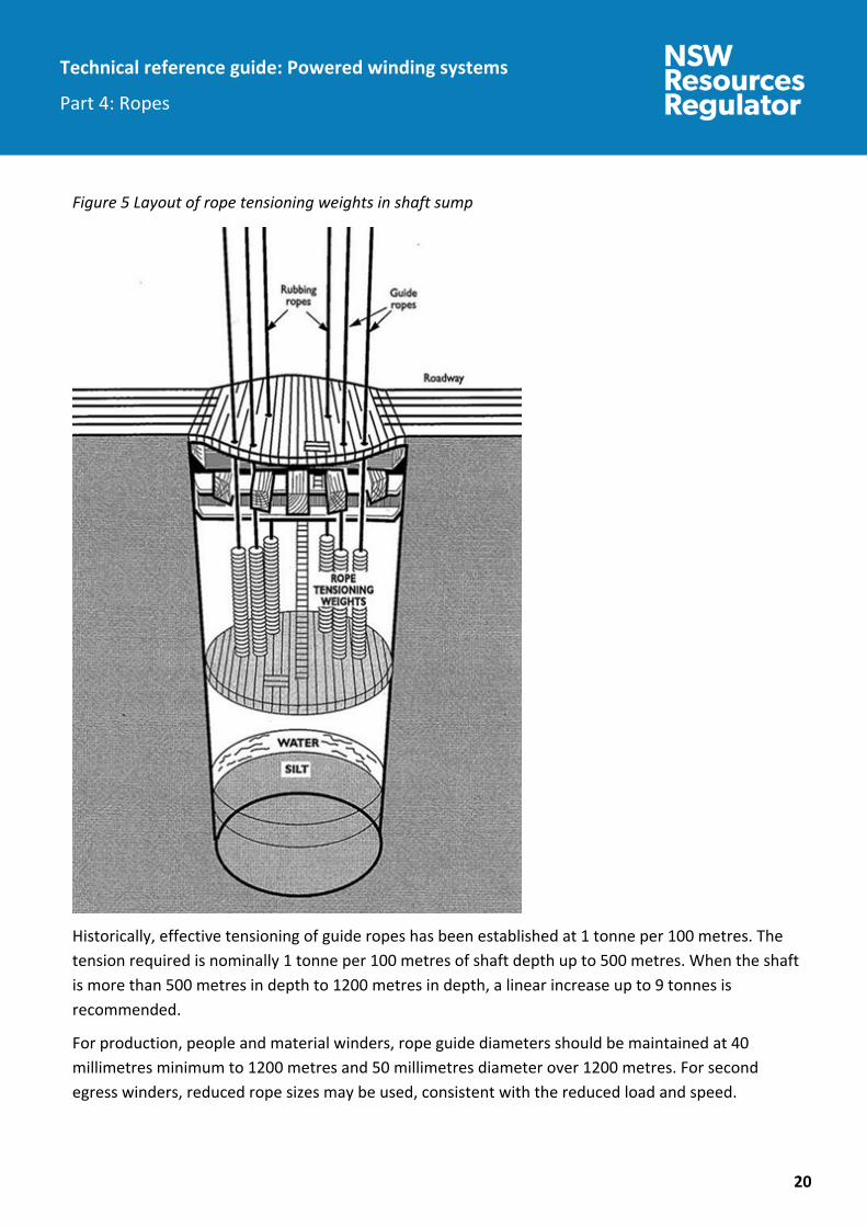
Figure 5 Layout of rope tensioning weights in shaft sump
Historically, effective tensioning of guide ropes has been established at 1 tonne per 100 metres. The tension required is nominally 1 tonne per 100 metres of shaft depth up to 500 metres. When the shaft is more than 500 metres in depth to 1200 metres in depth, a linear increase up to 9 tonnes is recommended.
For production, people and material winders, rope guide diameters should be maintained at 40 millimetres minimum to 1200 metres and 50 millimetres diameter over 1200 metres. For second egress winders, reduced rope sizes may be used, consistent with the reduced load and speed.

Technical reference guide: Powered winding systems
Part 4: Ropes
21
Figure 6 Guide methods used for conveyances

Technical reference guide: Powered winding systems
Part 4: Ropes
22
Figure 7 Typical guide rope layouts
2.5.4.2.1. Guide weight recommendations
DEPTH OF SHAFT (METRES)
MINIMUM SIZE OF GUIDE ROPES (MM)
MINIMUM GUIDE WEIGHT (TONNES)
A B C
0-200 30 3.0 2.5 2.0
200-400 34 4.0 3.5 3.0
400-600 38 5.0 4.5 4.0
600-800 42 6.0 5.5 5.0
800-1000 44 7.0 6.5 6.0
Operating depths greater than 1000 metres should be provided with detailed industry technical supportive evidence and rationale for all proposed ropes including sizes, specifications and factors of safety. The Swedish code of practice is one such example where operating parameters may be outside of the TRG: Powered winding systems series.
Technical reference guide: Powered winding systems
Part 4: Ropes
23
2.5.4.3. Suspension method Guides and rubbing ropes other than for shaft sinking should be suspended using spherically seated suspension glands. Guide and rubbing ropes must be restrained laterally at their lower extremities.
Consideration should be given to the design of the suspension system to allow for the following maintenance operations during the life of the system:
turning of guide ropes periodically to distribute wear evenly around the circumference of the rope
periodical movement of the guide ropes through the suspension gland.
2.5.4.4. Number of guide ropes The number of guide ropes has been found to depend on the depth of the shaft. The following minimum number of guide ropes should be used:
DEPTH NUMBER OF GUIDE ROPES
0 – 200 metres 2 guide ropes per conveyance
200 – 500 metres 3 guide ropes per conveyance
>500 metres 4 guide ropes per conveyance
2.5.4.5. Type of guide rope Guide and rubbing ropes should be half locked or locked coil construction rope. The outer wires should be sufficiently large to avoid frequent replacement due to wear. All wires should be rust resistant.
2.5.4.6. Guide rope clearances The clearance between conveyances and the conveyances and shaft walls should be no less than 500 millimetres.
Should lesser clearance be required, rubbing ropes should be used between conveyances when the clearance is between 100 metres to 300 metres.
Some mine shaft wall clearances to conveyance of nominal 300 millimetres have been shown inadequate and resultant in collision and impact scenarios. Where dimensions are nominally 300 millimetres and below, dynamic analysis is required. Factors such as guide and head rope layout and tensions, ventilation, shaft alignments, hoisting speeds and loads including Coriolis forces all affect

Technical reference guide: Powered winding systems
Part 4: Ropes
24
final operating clearances. Such analysis should be continued throughout the winder life to ensure stability and intended operating clearances are maintained.
3. Testing 3.1. Testing authority All destructive testing should be carried out by a testing authority certified in accordance with AS/NZS ISO 9001 and accredited by the National Association of Testing Authorities, Australia (NATA).
3.2. General The continued use of wire rope should not be based on any single test but rather, a combination of tests. Mines should not rely on non-destructive testing (NDT) alone.
The most definitive way of identifying the strength of the rope and therefore verifying the factor of safety is through destructive testing of a representative section of the rope. However, the factor of safety calculation as defined using the destructive test result is in reality only applicable for that end section of the rope that was destructively tested. Other areas along the rope may well have less or greater strength.
Destructive testing should be used in conjunction with NDT. This is because the sample of rope used for destructive testing may not be representative of the weakest section of the rope subsequent to damage or deterioration. In this case, the NDT will give a holistic indication of the condition of the rope.
All newly fitted ropes must have a sample taken for testing to validate the actual breaking force when new. This is used as a reference for future rope discard criteria.
Spare ropes that have been in storage for long periods of time can ‘age harden’ or be subject to corrosion through condensation etc. Any potential for these conditions to have occurred should cause a new test to be performed prior to the rope being placed into service.
The following provisions should apply to haulage ropes used in or about a mine:
the conveyance end of all drum winding ropes should be subject to a destructive test carried out by a certified NATA approved testing authority at intervals of not more than 12 months.
additional consideration and testing is required regarding the need for cropping the drum anchor end of the rope i.e. moving damage caused by the crossover point. This should be

Technical reference guide: Powered winding systems
Part 4: Ropes
25
based on NDT and include specific examination tests in these areas that may not normally be tested by the authority.
areas identified with potential problems of wear, damage, fatigue, corrosion, stress and vibration concentration and any other area that provides abnormal operating conditions, must be monitored appropriately with advice given by the authorised test authority.
destructive and NDT must not exceed 12 month intervals. A combination of testing using destructive and NDT methods is recommended. This provides detail for not only the end of rope but also over the rope length over any given period.
Rope management must be incorporated into the mechanical engineering control plan and include an appropriate audit/review component.
3.3. NDT equipment NDT or examinations should be conducted by a competent person using appropriately calibrated equipment. Adequate lighting and safe access to the wire rope should be provided.
The NDT instrument and associated accessories should comply with the following:
Be suitable for the environmental conditions in which it is to be used.
Be capable of operating in either direction.
sufficiently sensitive to detect a change in metallic cross-sectional area of the rope of 0.5%.
The instrument should produce a signal with an amplitude that is readily discernible from the background noise, while it is passed over a broken outer wire having a gap between the ends of 1 millimetre, in any rope construction and size in the range that is specified by the manufacturer.
The detection of the signal produced by the 1 millimetre gap in an outer wire should not be dependent on the location of the gap with respect to the sensing medium in the sensing head.
The test equipment should be positioned to maximise the amount of rope to be tested.
Discerning broken wire from background noise may not be possible where heavy corrosion is present.
Technical reference guide: Powered winding systems
Part 4: Ropes
26
3.4. Friction winder rope testing requirements
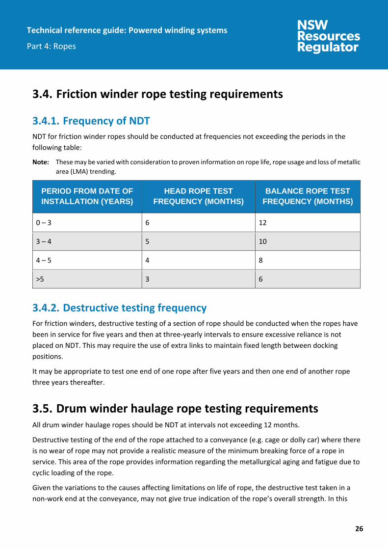
Frequency of NDT NDT for friction winder ropes should be conducted at frequencies not exceeding the periods in the following table:
These may be varied with consideration to proven information on rope life, rope usage and loss of metallic area (LMA) trending.
PERIOD FROM DATE OF INSTALLATION (YEARS)
HEAD ROPE TEST FREQUENCY (MONTHS)
BALANCE ROPE TEST FREQUENCY (MONTHS)
0 – 3 6 12
3 – 4 5 10
4 – 5 4 8
>5 3 6
Destructive testing frequency For friction winders, destructive testing of a section of rope should be conducted when the ropes have been in service for five years and then at three-yearly intervals to ensure excessive reliance is not placed on NDT. This may require the use of extra links to maintain fixed length between docking positions.
It may be appropriate to test one end of one rope after five years and then one end of another rope three years thereafter.
3.5. Drum winder haulage rope testing requirements All drum winder haulage ropes should be NDT at intervals not exceeding 12 months.
Destructive testing of the end of the rope attached to a conveyance (e.g. cage or dolly car) where there is no wear of rope may not provide a realistic measure of the minimum breaking force of a rope in service. This area of the rope provides information regarding the metallurgical aging and fatigue due to cyclic loading of the rope.
Given the variations to the causes affecting limitations on life of rope, the destructive test taken in a non-work end at the conveyance, may not give true indication of the rope’s overall strength. In this

Technical reference guide: Powered winding systems
Part 4: Ropes
27
case, a competent person may provide assessment through examination and report, outlining the details necessary relating the rope integrity and its ongoing use.
3.6. Further recommended tests
Frequency of NDT The frequency of NDT of all ropes used in any part of a PWS should be based on:
AS 4812
consideration of historical data, including variation to operational and maintenance details
a maximum period of 12 months unless otherwise stated in this document (head ropes being six months)
the degree of rope deterioration as further detailed in clause 3.6.3 ‘Increased frequency of NDT’
the further considerations as detailed in section 3 ‘Testing’
the maintenance strategy developed, including its periodic review.
Reference values of new rope All new ropes used in a PWS should undergo NDT within four weeks of being placed into service. This should take place after initial rope stretch but before any rope wear is likely to occur. The rope should be NDT by a NATA-recognised test authority and the rope diameter and the rope lay measured at nominated locations for use in determining future deterioration from the established datum points. This is to obtain a reference record, or a base line diameter and base line NDT report, for future comparison purposes. This will establish and identify the extent of any anomalies in the rope that may have resulted during manufacture, installation or storage.
It may not always be possible to perform the full rope length NDT on a project that requires progressively increasing depth such as a shaft sinking stage. An assessment should be made regarding project duration. A project extending greater than six months should warrant the rope length throughout the project to be tested and evaluated.
Increased frequency of NDT NDT should be more frequent than specified in clause 3.6.1 ‘Frequency of NDT’ where the following conditions apply:
Technical reference guide: Powered winding systems
Part 4: Ropes
28
The system uses a single rope for the haulage of people (as opposed to multiple ropes) or hauling material.
The minimum permissible factor of safety is being approached.
LMA exceeds a predetermined figure for the type of rope construction and duty.
An anomaly or deterioration is identified or suspected as follows:
significant corrosion relevant to the diameter of the individual wires
presence of broken wires that have not been identified as being insignificant
noticeable wear of the outer wires
loss of rope diameter since the original settling in period
increasing number of broken wires
fatigue failures of wires are indicated
a kink is or has been present
increase in rope diameter
large amounts of corrosion in a small area
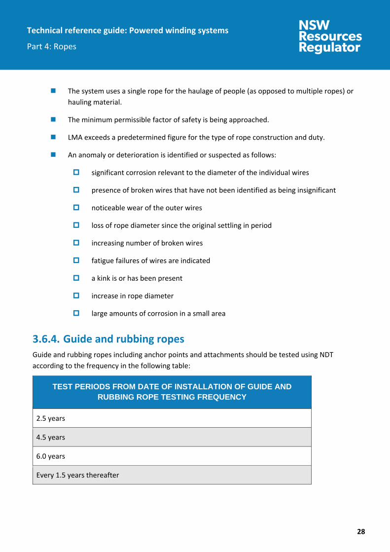
Guide and rubbing ropes Guide and rubbing ropes including anchor points and attachments should be tested using NDT according to the frequency in the following table:
TEST PERIODS FROM DATE OF INSTALLATION OF GUIDE AND RUBBING ROPE TESTING FREQUENCY
2.5 years
4.5 years
6.0 years
Every 1.5 years thereafter

Technical reference guide: Powered winding systems
Part 4: Ropes
29
Figure 8 Vertical shaft friction winder head and guide ropes
Figure 9 Vertical shaft friction winder balance and guide ropes
Technical reference guide: Powered winding systems
Part 4: Ropes
30
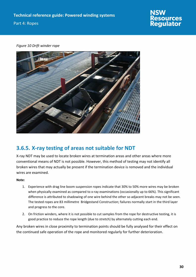
Figure 10 Drift winder rope
X-ray testing of areas not suitable for NDT X-ray NDT may be used to locate broken wires at termination areas and other areas where more conventional means of NDT is not possible. However, this method of testing may not identify all broken wires that may actually be present if the termination device is removed and the individual wires are examined.
1. Experience with drag line boom suspension ropes indicate that 30% to 50% more wires may be broken when physically examined as compared to x-ray examinations (occasionally up to 66%). This significant difference is attributed to shadowing of one wire behind the other so adjacent breaks may not be seen. The tested ropes are 83 millimetre Bridgestand Construction; failures normally start in the third layer and progress to the core.
2. On friction winders, where it is not possible to cut samples from the rope for destructive testing, it is good practice to reduce the rope length (due to stretch) by alternately cutting each end.
Any broken wires in close proximity to termination points should be fully analysed for their effect on the continued safe operation of the rope and monitored regularly for further deterioration.
Technical reference guide: Powered winding systems
Part 4: Ropes
31
4. Examination 4.1. General requirements General rope examination requirements are as follows:
Visual examination by a competent person at intervals not exceeding 24 hours. This examination should be carried out at a winding speed (typically at 1 m/s minimum) to enable visual clarity of any abnormalities that may arise.
Every rope used in a PWS should be examined and measured at intervals not exceeding 28 days.
In the course of an examination referred to in item 2 above, every rope should be thoroughly cleaned at the following places:
at all places liable to deterioration
in the case of shaft winding ropes – at places not more than 100 metres apart.
in the case of any other rope – should not be more than 300 metres apart.
During the cleaning of a rope as referred to in item 3 above, the circumference, diameter and lay length should be measured and the surface condition of the rope, any wire fractures and wear should be examined.
Other ropes used in winding or haulage apparatus should be regularly inspected at such places and frequencies nominated by the mine. These should be included in the mine maintenance schedules.
The lubrication or dressing of ropes used in PWS should be maintained.
Areas identified with potential problems subsequent from destructive and NDT should have causes, inclusive of their examination frequency and details reviewed with the authorised test authority. Recommendations should be applied such that rope integrity and compliance with associated discard criteria is adhered.

Technical reference guide: Powered winding systems
Part 4: Ropes
32
4.2. Guide rope inspection and rotation Guide and rubbing ropes for shaft winders should be periodically examined for wear and general condition. They should be cleaned, examined and measured at all points prone to deterioration, and other selected positions along their length, including those sections above and below the top and bottom landings or the middle of the shaft.
The interval between these examinations should not exceed 12 months. A record should be maintained of all measurements as well as the inspection and assessment comments.
Guide ropes tend to wear unevenly because of the rubbing action of conveyance shoes at positions where the lateral movement is greatest (e.g. entrances to the fixed guides, top and bottom landings). Where uneven wear occurs, it is usual practice to rotate the guide ropes at time intervals in order to equalise wear.
To minimise the effect of fatigue at a point where vibration is arrested (at the gland), the ropes should be lifted at appropriate intervals (through a distance of not less than 1.5 times the length within the capping or gland) and the termination remade.
Any rotation or lifting of the guide or rubbing ropes should be recorded in the guide rope documentation.
4.3. Visual examinations – guidance notes The mechanical engineering control plan should include identification of the requirements for all examinations. This should include details for the examination, frequency and documentation requirements.
Visual inspections should be conducted by a person having the appropriate experience, knowledge and information for the type of the examination to be conducted.
People conducting visual examinations should be shown capable and competent in the areas nominated within the rope’s examination criteria.
Safe access to the wire rope for cleaning, close examination and measurement should be provided.
Adequate lighting should be provided. A cap lamp may not be suitable for some examinations.
The entire length of the rope should be visually examined. Particular attention should be given to the following areas:
All areas not examined by NDT.
All areas having visual anomalies such as kinks, concentrated wear, damage ,corrosion or wire separation etc.

Technical reference guide: Powered winding systems
Part 4: Ropes
33
All areas having anomalies, including those previously detected by NDT methods.
Areas in close proximity to anchor points and attachments.
Where the rope rests on the sheaves.
Corrosion-prone areas. This may be dependent on:
ventilation flow direction
water ingress
location in the shaft
the difference in the strata composition which may affect the water chemistry locally.
On all winding drums where:
a rope cross over point occurs
a change in rope lay occurs
the rope leaves the drum at the conveyance park/docking positions.
On friction winders where the:
rope leaves the drum at docking positions
loop formed at the bottom of the balance ropes for the docking positions.
On drift winders where the rope:
length moves sideways when the conveyance goes around a rail turn
from the rope attachment to the conveyance for a distance of a hundred metres from the conveyance.
Localised wear locations have been previously identified.
4.4. Records of visual examinations Details and records of visual examinations should include:
1. Detail of examination: date, time, person etc.

Technical reference guide: Powered winding systems
Part 4: Ropes
34
2. Broken wires: Record sufficient details to identify compliance with discard criteria as detailed in section 5 ‘Discard criteria’ including:
a. the number of wire breaks per lay length that occurs in a strand
b. the location of the lay length with the greatest number of wire breaks
c. the total number of wire breaks in the rope
d. details of broken wires near to any termination point
e. the rate of increase of broken wires.
3. Wear: Note the location and extent of wear over the circumference of the rope and measure the remaining wire width of individual wires at the point of heaviest wear, using a monocular microscope with graduations or a similar device capable of measuring linear and depth dimensions. Use calculation to determine the wire diameter and the degree of wear of the individual wires.
4. Corrosion: As far as possible, locate any corrosion on the surface or in the rope valleys, ascertain the extent of any corrosion on the surface of the rope and record the degree of pitting on the wire surface as compared to its diameter. In particular, any corrosion that has resulted in loosening of the outer wires should be recorded.
5. Change in rope diameter: Measure the rope diameter and, where possible, identify the cause of any change as compared to a reference position.
6. Change in lay length: Measure the lay length and, where possible, identify the cause of the change as compared to a reference position.
7. Distortion: Identify the type of distortion (e.g. bird cage, kink, severe bend, strand or core protrusion, slack strands, waviness) and describe its severity.
8. Miscellaneous: Miscellaneous anomalies include core splices, result of lightning strikes and combinations of the above anomalies that result in damage or change to the rope structure.
9. Identification and signature of examiner.
10. Sign off and action of supervisor
4.5. Wire rope diameter measurement The diameter of wire rope should be measured by a suitable device such as vernier or rope callipers with measurements made on a straight portion of the rope over the crowns of the strands.
Each measured diameter should be the average of four readings. These readings should be in two pairs with the pairs separated by a distance of one to two metres along the length of the rope. The two
Technical reference guide: Powered winding systems
Part 4: Ropes
35
readings in each pair should be at the same position along the rope but at not less than 60° to each other. If there is a clear line of rope wear, the rope diameter over this wear should be measured.
Variation to the foregoing may be warranted for some installation but this should be justified and documented by appropriate risk assessment and risk management processes. The location and cleaning of diameter measurements should be in accordance with clause 4.1 ‘General requirements’ as well as include all other areas where significant deterioration has occurred or is likely to occur.
4.6. Corrosion Corrosion is easily recognised when it occurs on the outside of a rope but when it occurs internally it poses additional risk because its extent cannot be identified and it can result in:
tension failure that occurs when corrosion is severe and the remaining metal area is insufficient to support the load
corrosion fatigue that is the most common cause of rope failure and it occurs readily once corrosion is present. Even slight corrosion can lead to fatigue, particularly if regular total loading is in the vicinity of one-quarter of the original breaking force of the rope. Where corrosion is well defined, fatigue failure can occur at one-tenth of the original breaking force.
High tensile wires are more prone to failure by corrosion fatigue.
Severe corrosion may cause decreased elasticity of the rope.
In cases of severe corrosion, loss in rope breaking force could exceed three times the proportion of loss in metallic area (this has been shown by both Canadian research and NSW mine evidence).
It should be noted that small wire diameters are significantly more reduced in strength as a result of corrosion. This is because the outer wire proportion of cross section are the most effected by corrosion.
4.7. Non-destructive tests and examinations (NDT and NDE) – guidance notes
Length of wire rope to be NDT examined The choice of positions for the test equipment should allow as much as possible of the rope to be tested. More than one location may be needed, so that the full length of the rope may be covered. The rope between the following relevant positions should be tested (as much of the rope as possible):

Technical reference guide: Powered winding systems
Part 4: Ropes
36
1. For friction winder head and balance ropes: between attachment of the conveyance and attachment of the counterweight, as close as practicable to each one.
2. For drift and vertical shaft drum winders: between as close as practicable to the attachment and the rope’s contact with the drum while the rope is fully extended down the shaft.
Periodically at less frequency to normal NDT examination it may be appropriate to remove further layers from the drift and vertical shaft drum for NDT examination to determine corrosion, fretting and cross over point deterioration, particularly for a rope that has been turned end for end or that is infrequently double reeved for heavy lifts.
3. For static ropes such as guide and rubbing ropes; over the full length.
Limitations of NDT Appendix G ‘Limitations of NDT’ lists the many items that limit the ability and accuracy of NDT to measure and detect defects that may be present in a wire rope. Therefore, NDT should not be the only means used to determine the suitability of wire ropes to remain in service.
Records of NDT Details and records of NDT should include:
1. original test device trace records
2. registration details
3. customer name
4. location
5. date of testing
6. date of issue of the report
7. details and identification of the rope tested, including reference to the original test certificate
8. date of the rope installation
9. test report number
10. test method used
11. test equipment used
12. NDT and visual inspection results. Refer to clause 4.4 ‘Records of visual examinations’ for records of visual inspection results and the following for NDT examinations:
a. Appendix D ‘Rope life predictions based on correlations between non-destructive testing and destructive testing methods’.

Technical reference guide: Powered winding systems
Part 4: Ropes
37
b. Appendix E ‘Graphs showing area loss and local faults various rope installations’.
c. Appendix F ‘Diagrams of winding ropes examined by non-destructive testing’.
13. identification of the examiner, examiner’s signature on the report or that of an authorised signatory from their organisation on the report and their employer
14. statement on the rope condition with respect to the discard criteria given in this guideline, point by point.
The method of classifying anomalies should be identified or alternately sufficient details of the anomalies should be provided.
15. the rate of deterioration of the rope, incorporating the results of any previous relevant tests, in graphical form. A typical graphical report is shown in Appendix E ‘Graphs showing area loss and local faults various rope installations’.
16. reference and statement for compliance or otherwise to this guide.
17. a recommendation by the competent person that the period before the next examination be reduced if the historical analysis of records indicate that the discard criteria condition may occur before the next normally scheduled NDT examination.
18. a clear statement including a diagrammatic layout as detailed in Appendix F ‘Diagrams of winding ropes examined by NDT’ to identify the extent of the rope examined and not examined. This should include locations of the NDT instruments, sheaves, drums and conveyance.
19. maximum loss of magnetic area relevant to the least deteriorated section of rope (the area used should be identified on the report). Any limitation or reason why NDT result may be unreliable, e.g. severe corrosion masking local faults.
20. Results of visual examinations as detailed in:
a. clause 4.1 ‘General requirements’
b. clause 4.3 ‘Visual examinations – guidance notes’
c. clause 4.4 ‘Records of visual examinations’
d. clause 4.5 ‘Wire rope diameter measurement’.
21. The test reports of any examination should be retained.
Information gathered during the lifetime of the rope may be useful and could help identify trends if there is a common fault in the system.

Technical reference guide: Powered winding systems
Part 4: Ropes
38
Actions following a NDT examination The person who conducts the NDT should follow up the tests by conducting a visual examination of appropriate sections of the ropes that include in particular the areas identified by the NDT where deterioration may be present.
If the NDT-competent person has any doubt or concern following from inspection or tests relating to compliance with this guide then this concern should be documented and followed up by a dedicated specialist and competent person for inspection, testing and evaluation of wire ropes. A detailed examination should be provided following such concern and a statement about the suitability of the wire rope provided for the rope’s continued use.
If anything is identified during inspection by a competent person that in the opinion of that person requires urgent corrective action, then this should be communicated in writing to the most senior official at the mine before the competent person leaves the mine. It is the responsibility of the mine management to decide the appropriate course of action.
4.8. Further guidance notes If a rope exhibits any abnormal or unusually accelerated deterioration of LMA, strength, diameter change, cracked wires, etc relating to areas of discard criteria, previous tests should be used in conjunction with testing of individual wires from a variety of previous rope samples as applicable.
Tests should be considered with the recognised authority and may include torsion, wrap or bend and weight of zinc loss tests to assist in establishing any necessary resolution or plans to maintain required compliance and safety.
Consideration should be given to the following factors:
1. Any changes in winding cycle, tonnes raised or load per cycle
2. Rope life
3. Any destructive test results for previous ropes
4. NDE test result data for the rope
5. Breaking force as determined by destructive testing compared with indicated LMA
6. Maintenance on rope drum and sheave groove profile/tread diameter
7. Records of monitoring of individual rope loads (multi-rope friction winders).

Technical reference guide: Powered winding systems
Part 4: Ropes
39
5. Discard criteria 5.1. General Ropes can deteriorate due to the cumulative effects of the following:
wear
corrosion
fatigue
physical damage such as kinks, impact, pinching etc.
broken wires
fretting
overheating
localised overheating
lightning.
All of the discard criteria should be complied with from sections 5.2 ‘Requirements’ and 5.3 ‘Further discard information’ .
5.2. Requirements The discard criteria requirements can be generally stated as necessary to ensure the rope factor of safety does not fall below the relevant rope factor of safety requirements for the winder type.
The rope (being head, balance, guide and rubbing ropes used in all drum and friction winders) should be discarded if any of the following occur:
1. Broken wires within one rope lay length visibly identified and or identified by NDT for:
a. non-uniformly distributed broken wires causing a loss of rope metallic area of more than 5%
b. uniformly distributed broken wires causing a loss of rope metallic area of more than 8%.
2. Broken wires within any one strand lay length as visibly identified and or identified by NDT resulting in:
a. excess of 15% of the total numbers of wires within any strand

Technical reference guide: Powered winding systems
Part 4: Ropes
40
b. the total number of broken wires in any strand being more than 40% of the total number of outer wires in the strand.
Filler wires are excluded from the latter because of the minimal contribution to breaking force.
3. Broken wires in adjacent lay lengths: the number of broken wires in five adjacent rope lay lengths is more than double that permitted for one rope lay length.
4. Broken wires in valleys: there is more than one visible broken wire within a rope lay due to in-service effects between strand to strand contact points in a rope valley.
5. Valley wire breaks are generally an indication of serious rope deterioration at strand-to-strand contact points and do not generally occur in isolation.
6. More than one broken wire is within one metre of any termination point as determined by visual or x-ray examination (NDT is often not suitable for examinations within one metre).
7. The projected rate of deterioration due to the number of broken wires is such that excess loss of breaking force may occur before the next scheduled test.
8. Outer wire wear: uniform rope wear of the outer wires over at least two rope lays has reduced the outer wire diameter by more than one third. Appendix B ‘Example: Effect of external wear on rope strength’ shows the effect on one type of rope construction.
9. Rope diameter: the rope diameter as determined in accordance with clause 4.5 ‘Wire rope diameter measurement’ has been reduced by more than 6%, due to wear, core diameter reduction or core deterioration or corrosion.
10. LMA: the LMA exceeds 6% unless a competent person recommends its continued use in writing. The LMA for ropes used should never exceed 10%. The maximum LMA for guide ropes may exceed 12% if recommended by a competent person and due consideration has been given to:
a. area of individual wires
b. potential for broken wires to catch at the guide contact point of the conveyance or counterweight
c. other discard criteria in this guideline.
11. Distortion: if there is distortion of the rope structure, such as waviness or kinks, the rope should be replaced unless a competent person has advised that it is satisfactory for continued service. If efforts are made to straighten and continue use of the rope, specific examinations at this point are to be included thereafter consistent with the NDT and examination requirements.
12. Heat damage: the damage due to heat effects has resulted in pitting, distortion or any other signs of damage.
Technical reference guide: Powered winding systems
Part 4: Ropes
41
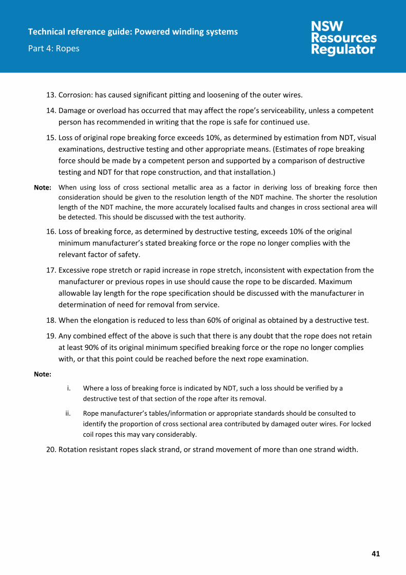
13. Corrosion: has caused significant pitting and loosening of the outer wires.
14. Damage or overload has occurred that may affect the rope’s serviceability, unless a competent person has recommended in writing that the rope is safe for continued use.
15. Loss of original rope breaking force exceeds 10%, as determined by estimation from NDT, visual examinations, destructive testing and other appropriate means. (Estimates of rope breaking force should be made by a competent person and supported by a comparison of destructive testing and NDT for that rope construction, and that installation.)
When using loss of cross sectional metallic area as a factor in deriving loss of breaking force then consideration should be given to the resolution length of the NDT machine. The shorter the resolution length of the NDT machine, the more accurately localised faults and changes in cross sectional area will be detected. This should be discussed with the test authority.
16. Loss of breaking force, as determined by destructive testing, exceeds 10% of the original minimum manufacturer’s stated breaking force or the rope no longer complies with the relevant factor of safety.
17. Excessive rope stretch or rapid increase in rope stretch, inconsistent with expectation from the manufacturer or previous ropes in use should cause the rope to be discarded. Maximum allowable lay length for the rope specification should be discussed with the manufacturer in determination of need for removal from service.
18. When the elongation is reduced to less than 60% of original as obtained by a destructive test.
19. Any combined effect of the above is such that there is any doubt that the rope does not retain at least 90% of its original minimum specified breaking force or the rope no longer complies with, or that this point could be reached before the next rope examination.
i. Where a loss of breaking force is indicated by NDT, such a loss should be verified by a destructive test of that section of the rope after its removal.
ii. Rope manufacturer’s tables/information or appropriate standards should be consulted to identify the proportion of cross sectional area contributed by damaged outer wires. For locked coil ropes this may vary considerably.
20. Rotation resistant ropes slack strand, or strand movement of more than one strand width.

Technical reference guide: Powered winding systems
Part 4: Ropes
42
5.3. Further discard information
General Discard may be deferred if adequate information is available to ensure the rope factors of safety requirements are complied with and continued use is recommended by a competent person.
Information should include comparison between destructive testing and NDT for the particular rope construction and installation characteristics. Appendix C ‘Comparison between the loss of metallic area and strength as measured by non-destructive testing and destructive testing’ and Appendix D ‘Rope life predictions based on correlations between non-destructive testing and destructive testing’ list such a comparison between loss of area and rope strength for ropes used at several NSW coal mines.
Where, for example, the original factor of safety is 15, and at the time of deciding whether to discard the rope the factor of safety is 10, this would indicate excessive wear and a rope in poor condition deteriorating faster than a new rope with a factor of safety of 10.
A good guideline would be for a rope to be discarded when it has lost 10% of its original breaking strength or 10% of its original metallic area.
Fatigue fractures When a wire is deteriorating due to fatigue, it will show no visible signs of fatigue until it has undergone more than 90% of the loading necessary to break it, then a small crack will appear on the surface of the wire.
The crack will likely extend only part of the way across before the weakened wire snaps by bending.
If the fatigue fractures only occur on worn crowns, then the fatigue may be due to surface embrittlement.
Surface embrittlement When rope steel is heated above 700o C and is then suddenly cooled or quenched, the steel becomes very hard and brittle because it has changed to a ‘martensite’ structure.
This can readily occur when the outer wires of the rope rub heavily on another surface causing the localised temperature to rise, which will suddenly cool as soon as the rubbing stops. The remainder of the wire below the rubbing surface takes the heat away. The martensite may only be 0.08 millimetres and is not detectable by eye.
Martensite can be suspected when wires break at crowns and at no other places and when wear is insufficient for the fractures to be explained by loss of metal and breaking force.

Technical reference guide: Powered winding systems
Part 4: Ropes
43
It should also be noted that if wire rope becomes heated to a lesser temperature as low as 300o C, annealing or softening of the steel will occur. This also contributes to a loss of wire tensile strength and ultimate rope breaking force. The actual temperature and the time for which the sections of rope have been exposed to this temperature will determine the amount of loss of breaking force.
Powered winder operators should ensure there are no rubbing points along the entire length of rope travel. Guiding rollers and sheaves should be inspected for freedom of movement and within tolerances for allowable wear.
Further resources The following Australian Standards are useful for gaining an understanding of rope construction and deterioration:
Although these Standards include information regarding rope discard criteria, it is not intended that this is used for PWS ropes.
AS 2759
AS 1735.2
AS 3569
ISO 4309
The following may be suitable for PWS ropes:
The Ropeman’s Handbook (National Coal Board London)
SABS 0293.

Technical reference guide: Powered winding systems
Part 4: Ropes
44
6. Records The following records relating to each rope installation should be retained at the mine:
rope specifications, rope load calculations and date of installation
reports of all examinations and inspections
historical data for previously installed ropes with comparisons to destructive testing of sections where NDT methods have identified anomalies or areas of significant deterioration
maintenance records for monitoring of rope drum/sheave groove or tread diameter, relocation of rope on the drift and vertical shaft drum (putting spare rope into service to shift cross over points) rotation of guide or rubbing ropes to expose fresh rope surface to guides, and similar
dates on which ropes were recapped
copies of all NDT reports
copies of all detailed visible examinations for the ropes in service. Winding cycles achieved for each rope in the winding system and tonnage conveyed in the case of production winders.
original rope manufacturer data sheet
initial NDT tests
all records of defects identified

Technical reference guide: Powered winding systems
Part 4: Ropes
45
Appendices
Appendix A – References
Relevant Australian Standards AS 1065 AS 1065 Non-destructive testing - Ultrasonic testing of carbon and low
alloy steel forgings
AS 1085.1 AS 1085.1 Railway track material – Steel rails
AS 1085.2 AS 1085.2 Railway track material - Fishplates
AS 1085.3 AS 1085.3 Railway track material - Sleeper plates
AS 1085.4 AS 1085.4 Railway track material - Fishbolts and nuts
AS 1085.7 AS 1085.7 Railway track material - Spring washers
AS 1085.8 AS 1085.8 Railway track material - Dogspikes
AS 1085.10 AS 1085.10 Railway track material - Rail anchors
AS 1085.12 AS 1085.12 Railway track material - Insulated joint assemblies
AS 1085.13 AS 1085.13 Railway track material - Spring fastening spikes for sleeper plates
AS 1085.14 AS 1085.14 Railway track material - Prestressed concrete sleepers
AS 1085.17 AS 1085.17 Railway track material - Steel sleepers
AS 1085.18 AS 1085.18 Railway track material - Screw spikes and threaded inserts
AS 1085.19 AS 1085.19 Railway track material - Resilient fastening assemblies
AS 1085.20 AS 1085.20 Railway track material - Welding of steel rail
AS 1085.21 AS 1085.21 Railway track material - Turnouts, switches and crossings
AS/NZS 1170.0 AS/NZS 1170.0 Structural design actions - General principles
AS 1171-1998 AS 1171 Non-destructive testing - Magnetic particle testing of ferromagnetic products, components and structures
AS 1210-2010 AS 1210 Pressure vessels

Technical reference guide: Powered winding systems
Part 4: Ropes
46
AS 1403 AS 1403 Design of rotating steel shafts
AS 1554.1 AS 1554.1 Structural steel welding –Welding of steel structures
AS/NZS 1554.4 AS/NZS 1554.4 Structural steel welding - Welding of high strength quenched and tempered steels
AS/NZS 1554.5 AS/NZS 1554.5 Structural steel welding - Welding of steel structures subject to high levels of fatigue loading
AS 1657 AS 1657 Fixed platforms, walkways, stairways and ladders - Design, construction and installation
AS 1670.1 AS 1670.1 Fire detection, warning, control and intercom systems - System design, installation and commissioning - Fire
AS 1710 AS 1710 Non-destructive testing - Ultrasonic testing of carbon and low alloy steel plate and universal sections - Test methods and quality classification
AS 1735.2 AS 1735.2 Lifts, escalators and moving walks - Passenger and goods lifts – Electric
AS 2574 AS 2574 Non-destructive testing - Ultrasonic testing of ferritic steel castings
AS 2671 AS 2671 Hydraulic fluid power - General requirements for systems (ISO 4413, MOD)
AS 2759 AS 2759 Steel wire rope - Use, operation and maintenance
AS 2788 AS 2788 Pneumatic fluid power - General requirements for systems (ISO 4414, MOD)
AS 3507.2 AS 3507.2 Non-destructive testing - Radiographic determination of quality of ferrous castings
AS 3569 AS 3569 Steel wire ropes - Product specification
AS 3600 AS 3600 Concrete structures

Technical reference guide: Powered winding systems
Part 4: Ropes
47
AS 3637.1 AS 3637.1 Underground mining - Winding suspension equipment - General requirements
AS 3637.2 AS 3637.2 Underground mining - Winding suspension equipment - Detaching hooks
AS 3637.3 AS 3637.3 Underground mining - Winding suspension equipment - Rope cappings
AS 3637.4 AS 3637.4 Underground mining - Winding suspension equipment - Drawbars and connecting links
AS 3637.5 AS 3637.5 Underground mining - Winding suspension equipment - Rope swivels and swivel hooks
AS 3637.6 AS 3637.6 Underground mining - Winding suspension equipment - Shackles and chains
AS 3751 AS 3751 Underground mining - Slope haulage - Couplings, drawbars, and safety chains
AS 3785.1 AS 3785.1 Underground mining - Shaft equipment - Shaft overwind safety catch system
AS 3785.2 AS 3785.2 Underground mining - Shaft equipment - Shaft winding arresting systems
AS 3785.3 AS 3785.3 Underground mining - Shaft equipment - Drum winding gripper systems
AS/NZS 3785.4 AS/NZS 3785.4 Underground mining - Shaft equipment - Conveyances for vertical shafts
AS 3785.5 AS 3785.5 Underground mining - Shaft equipment - Headframes
AS/NZS 3785.6 AS/NZS 3785.6 Underground mining - Shaft equipment - Fixed guides, rope guides and rubbing ropes for conveyances
AS 3785.7 AS 3785.7 Underground mining - Shaft equipment - Sheaves

Technical reference guide: Powered winding systems
Part 4: Ropes
48
AS/NZS 3785.8 AS/NZS 3785.8 Underground mining - Shaft equipment - Conveyances for inclined shafts
AS 3990 AS 3990 Mechanical equipment - Steelwork
AS 4024 AS 4024 safety of machinery series of standards
AS 4024.1 AS 4024.1 Series Safety of Machinery (all sub-Parts as applicable)
AS/NZS 4024.1204
Safety of machinery – Electrical equipment of machines - General requirements (IEC 60204-1:2016 (ED. 6.0) MOD)
AS 4024.1503 Safety of machinery- Safety-related parts of control systems—General principles for design’
AS 4024.1604 Safety of machinery - Design of controls, interlocks and guarding—Emergency stop—Principles for design
AS 4100 AS 4100 Steel structures
AS 4730.2 AS 4730.2 Mining - Winding equipment - Braking systems
AS/NZS 4812 AS/NZS 4812 Non-destructive examination and discard criteria for wire ropes in mine winding systems
AS 60529 Degrees of protection provided by enclosures (IP Code)
AS 61508 Series Functional safety of electrical/electronic/programmable electronic safety-related systems
AS 61511 AS 61511 series of standards ‘Functional safety – Safety instrumented systems for the process industry sector’
AS 62061 Safety of machinery – Functional safety of safety-related electrical, electronic and programmable electronic control systems
AS/NZS ISO 9001 AS/NZS ISO 9001 Quality Management Systems - Requirements
AS ISO 31000 AS ISO 31000 Risk management - Guidelines

Technical reference guide: Powered winding systems
Part 4: Ropes
49
International standards ISO 286-1 ISO 286-1 : Geometrical product specifications (GPS) - ISO code system for
tolerances on linear sizes - Part 1: Basis of tolerances, deviations and fits
BS 7608 BS 7608 Guide to fatigue design and assessment of steel products
ISO Guide 73 ISO Guide 73 Risk management - Vocabulary
ISO 4309 ISO 4309 Cranes - Wire ropes - Care and maintenance, inspection and discard
ISO 4413 ISO 4413 Hydraulic fluid power - General rules and safety requirements for systems and their components
ISO 4414 ISO 4414 Pneumatic fluid power - General rules and safety requirements for systems and their components
IEC 31010 IEC 31010 Ed. 2.0 (Bilingual 2009) Risk management - Risk assessment techniques
ISO 12100 ISO 12100 Safety of machinery – General principles for design – Risk assessment and risk reduction
Other Reference
Safe man riding in Mines parts 1A and 1B, parts 2A and 2B, being the first and second report of the National Committee for Safety of man riding in shafts and unwalkable Outlets.
SABS 0293 Condition assessment of steel wire ropes on mine winders code of practice
ASTM E1571 – 11(2016)e1
Standard Practice for Electromagnetic Examination of Ferromagnetic Steel Wire Rope

Technical reference guide: Powered winding systems
Part 4: Ropes
50
Appendix B – Example: Effect of external wear on rope strength The following is an extract from ‘Quantitative in service inspection of wire rope’ by Herbert R. Weischedel as printed in Materials evaluation/46/March 1988.
A rope of 6 x 7 fibre core with external abrasion results in the loss of one third of the diameter of the outer wires, which translates into a 30% loss of metallic area (LMA) or a breaking strength loss of the outer wires. The wear equated to a 43% LMA of the entire rope.
The surface wires form a helix. As we proceed along the rope in the longitudinal direction, each surface wire of the strand will consecutively assume the position of the rope surface wires. Hence within a short distance, well within the recovery distance, each strand surface wire will consequently suffer a 30% loss of cross section. Therefore, all 36 surface wires to the 6 strands contribute equally to the overall strength loss, not just the rope surface wires. Thus, the total strength loss for this rope is 25.7%, and the rope should not be in service.
However, consideration should take into account the fact that most ropes, when surface wear is present, are shown by experience to be predominantly worn in “patches” and on one side of the rope rather than uniformly around the circumference or periphery. It is not the intention of the guideline to force any rope into discard as a result of a few outer wires which may be worn such that the wire diameter is less than one third of the original and possibly offering no great loss to the rope than a few broken wires. Hence a pragmatic approach is necessary when considering wear on the outer wires.

Technical reference guide: Powered winding systems
Part 4: Ropes
51
Appendix C – Comparison between loss of metallic area and strength as measured by non-destructive and destructive testing E1 EXAMPLE 1
WINDER vertical friction winder
ROPE LOCATION head rope
ROPE CONSTRUCTION 28mm 6x12/12/9 fibre core, triangular strand, galvanised
ROPE SERVICE 5 years
ROPE CONDITION Some corrosion and pitting of surface wires evident at several sections of the rope, including within one metre of counterweight
MAXIMUM AREA LOSS 6.4% as measured by non-destructive testing
MAXIMUM STRENGTH LOSS 20% as measured by destructive testing
E2 EXAMPLE 2
WINDER vertical friction winder
ROPE head rope
ROPE CONSTRUCTION 30mm 6x12/12/9 pre post formed RHLL
ROPE SERVICE 4 years
ROPE CONDITION Some wear and indentations evident
MAXIMUM AREA LOSS 16.5% as measured by non-destructive testing
MAXIMUM STRENGTH LOSS 15.5% as measured by destructive testing

Technical reference guide: Powered winding systems
Part 4: Ropes
52
E3 EXAMPLE 3
WINDER Drift
ROPE Haulage
ROPE CONSTRUCTION 27mm 6x7/3 FS B1770 RHLL
ROPE SERVICE 10 months
ROPE CONDITION Medium external wear and corrosion and light internal wear and corrosion in inbye end, with the worst area stated to be at a kink
MAXIMUM AREA LOSS 7.2% as measured by non-destructive testing
MAXIMUM STRENGTH LOSS 37% as measured by destructive testing 2 months after the above NDT was carried out
E4 EXAMPLE 4 (SEE ROPE NO. E IN APPENDIX D)
WINDER Drift
ROPE Haulage
ROPE CONSTRUCTION 38mm 6x23 (10/12/39) RHLL
ROPE SERVICE 2.5 years
ROPE CONDITION Moderate wear with 28.5% wire diameter loss observed
MAXIMUM AREA LOSS 18.5% as measured by non-destructive testing
MAXIMUM STRENGTH LOSS 37.4% as measured by destructive testing 2 months after the above NDT was carried out

Technical reference guide: Powered winding systems
Part 4: Ropes
53
Appendix D – Rope life predictions based on correlations between non-destructive and destructive testing methods

Technical reference guide: Powered winding systems
Part 4: Ropes
54
Appendix E - Graphs showing area loss and local faults various rope installations

Technical reference guide: Powered winding systems
Part 4: Ropes
55

Technical reference guide: Powered winding systems
Part 4: Ropes
56

Technical reference guide: Powered winding systems
Part 4: Ropes
57

Technical reference guide: Powered winding systems
Part 4: Ropes
58

Technical reference guide: Powered winding systems
Part 4: Ropes
59
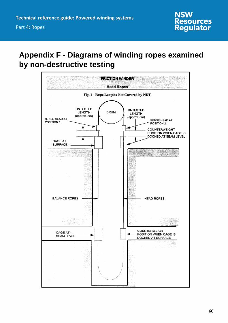
Technical reference guide: Powered winding systems
Part 4: Ropes
60
Appendix F - Diagrams of winding ropes examined by non-destructive testing

Technical reference guide: Powered winding systems
Part 4: Ropes
61

Technical reference guide: Powered winding systems
Part 4: Ropes
62
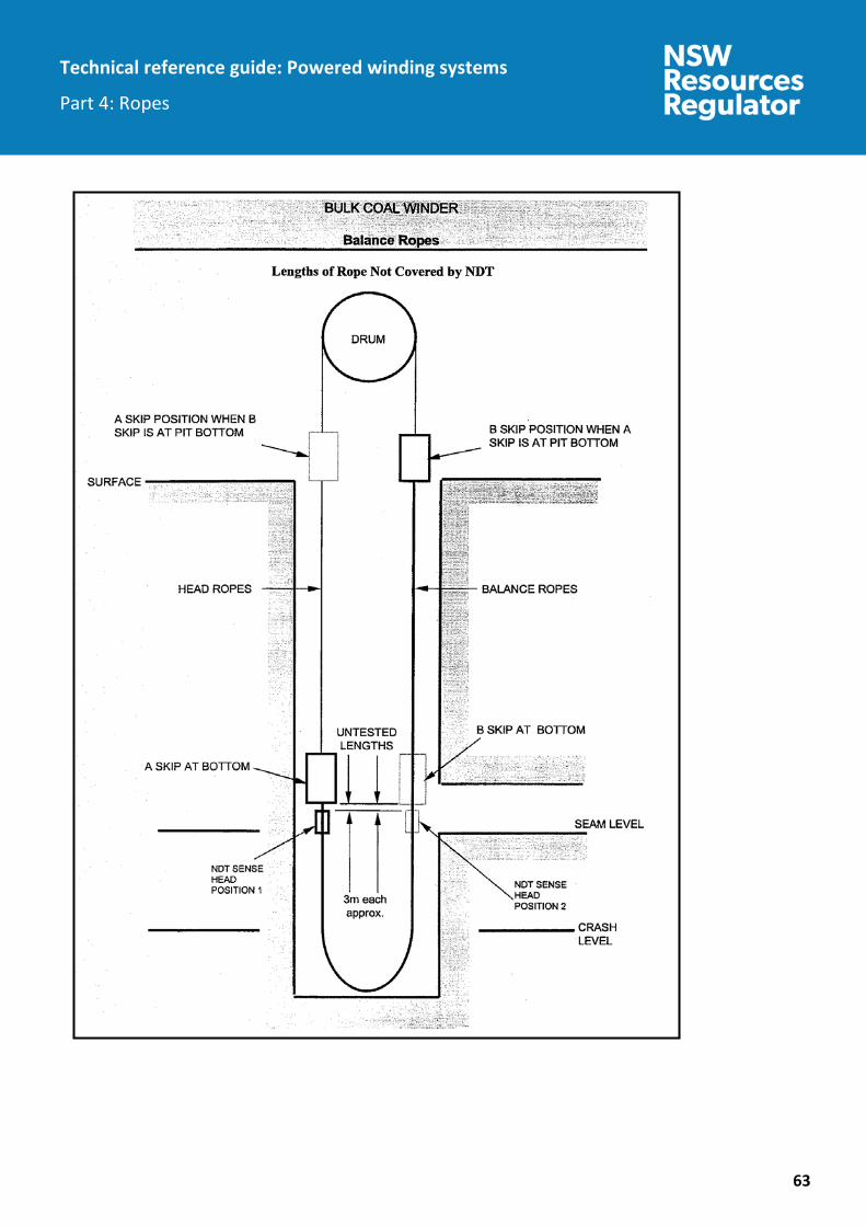
Technical reference guide: Powered winding systems
Part 4: Ropes
63

Technical reference guide: Powered winding systems
Part 4: Ropes
64

Technical reference guide: Powered winding systems
Part 4: Ropes
65

Technical reference guide: Powered winding systems
Part 4: Ropes
66
Technical reference guide: Powered winding systems
Part 4: Ropes
67
Appendix G – Limitations of NDT The limitations of NDT instruments to detect defects in wire ropes include the following:
1. It can only be used for ferromagnetic ropes.
2. It is difficult, if not impossible, to detect flaws at or near rope terminations and ferromagnetic steel connections.
3. Deterioration of a metallurgical nature (e.g. embrittlement, plastic deformation or fatigue) is not detectable until wires break.
4. The instrument is limited to rope speeds specified by the manufacturer.
5. The sensitivity of NDT method decreases with the depth of flaw from the surface.
6. Signals due to the presence of corrosion in a rope may make individual anomalies / local faults indistinguishable.
7. Internal broken wires may not be detected, as an air gap is needed before NDT will indicate a break.
8. Measurements of change in metallic cross-sectional area may be limited to showing comparative changes at various positions along the rope rather than the deterioration from the new rope.
9. Some rope constructions (e.g. full locked coil) may not be magnetically saturated by the NDT machine, especially if the diameter is near to the upper limit of the sensor range. In such cases, the ability of the NDT machine to detect LMA and local faults (LF) may be seriously impaired.
10. The site location of the NDT equipment which may result in interference from:
a. adjacent steel structure
b. other wire ropes
c. hand held radios, other electronic communication / devices including any rope for transmitting communications in the shaft.
d. external electrical sources or magnetic fields may cause interference and hence affect the results
11. The % loss of area as measured by NDT does not necessarily indicate % loss of rope breaking force.
12. Any relationship established between rope breaking force as established by destructive testing and NDT LMA may vary considerably so it should not be totally relied on for identifying the

Technical reference guide: Powered winding systems
Part 4: Ropes
68
remaining strength of a rope still in service. Extensive comparisons between NDT LMA and destructive testing can at least give some guidance.
13. Lack of experience / care / knowledge by the operator.
14. Accuracy of the NDT equipment.
15. Type and size of faults in the rope.