Harsh Saini , Abhinav Bhatia, , Hemant Kr. Soni …Fig-4: Field winding of DC motor 2.4 Winding...
7
International Research Journal of Engineering and Technology (IRJET) e-ISSN: 2395 -0056 Volume: 04 Issue: 03 | Mar -2017 www.irjet.net p-ISSN: 2395-0072 © 2017, IRJET | Impact Factor value: 5.181 | ISO 9001:2008 Certified Journal | Page 1855 DESIGN OF 1 KW DC MOTOR Harsh Saini , Abhinav Bhatia, , Hemant Kr. Soni, Himanshu Sharma Student, Electrical Engineering, Poornima College Of Engineering, Rajasthan, India Student, Electrical Engineering, Poornima College Of Engineering, Rajasthan, India Student, Electrical Engineering, Poornima College Of Engineering, Rajasthan, India Student, Electrical Engineering, Poornima College Of Engineering, Rajasthan, India ---------------------------------------------------------------------***--------------------------------------------------------------------- Abstract: The theoretical knowledge about the motor deigning is not enough to construct the motor in practical world. This paper consists the full process to design the 1 KW dc motor. In this paper the design of a 1KW dc motor with its all specific parts are done. What consists stator part like yoke, pole shoe, pole core, brushes, commutator, field winding etc. The design of rotating part like armature, armature winding, no of slots in armature windings are also explained in this paper for 1 KW dc motor. It also includes specific parameters used for designing 1KW dc motor like stator length, no of poles, no of turns in field winding. Copper Material with its mechanical strength is explained for making the field winding and armature winding. The cast iron is used as the protecting material for motor. Output questions like maximum speed of motor, torque generated for the motor are also calculated on the basis of these parameters. Keywords: Stator, rotor, commutator, pole, field windings, armature windings 1. INTRODUCTION A DC motor is an internally commutated electric motor designed to be run from a direct current power source. Brushed motors were the first commercially significant application of electric power to pouring mechanical energy and DC distribution systems were used for more than 100 years to work motors in commercial and manufacturing buildings. Brushed DC motors can be different in speed by changing the operating voltage or the strength of the magnetic field. Depending on the connections of the field to the power supply, the speed and torque characteristics of a brushed motor can be different to provide steady speed or speed inversely proportional to the mechanical load. Fig-1: 1 KW DC motor Brushed motors remain to be used for electrical propulsion, cranes, paper machines and steel rolling mills. Since the brushes wear down and need replacement. The dc motors are also used in Lathes machine, Drills, Boring mills, Shaper, Revolving and weaving machines etc. 2. STATOR PART OF DC MOTOR 2.1 Yoke of DC motor Fig-2: Yoke of DC motor
Transcript of Harsh Saini , Abhinav Bhatia, , Hemant Kr. Soni …Fig-4: Field winding of DC motor 2.4 Winding...
International Research Journal of Engineering and Technology (IRJET) e-ISSN: 2395 -0056
Volume: 04 Issue: 03 | Mar -2017 www.irjet.net p-ISSN: 2395-0072
© 2017, IRJET | Impact Factor value: 5.181 | ISO 9001:2008 Certified Journal | Page 1855
DESIGN OF 1 KW DC MOTOR
Harsh Saini , Abhinav Bhatia, , Hemant Kr. Soni, Himanshu Sharma
Student, Electrical Engineering, Poornima College Of Engineering, Rajasthan, India Student, Electrical Engineering, Poornima College Of Engineering, Rajasthan, India
Student, Electrical Engineering, Poornima College Of Engineering, Rajasthan, India Student, Electrical Engineering, Poornima College Of Engineering, Rajasthan, India
---------------------------------------------------------------------***---------------------------------------------------------------------
Abstract: The theoretical knowledge about the motor
deigning is not enough to construct the motor in practical world. This paper consists the full process to design the 1 KW dc motor. In this paper the design of a 1KW dc motor with its all specific parts are done. What consists stator part like yoke, pole shoe, pole core, brushes, commutator, field winding etc. The design of rotating part like armature, armature winding, no of slots in armature windings are also explained in this paper for 1 KW dc motor. It also includes specific parameters used for designing 1KW dc motor like stator length, no of poles, no of turns in field winding. Copper Material with its mechanical strength is explained for making the field winding and armature winding. The cast iron is used as the protecting material for motor. Output questions like maximum speed of motor, torque generated for the motor are also calculated on the basis of these parameters.
Keywords: Stator, rotor, commutator, pole, field windings,
armature windings
1. INTRODUCTION
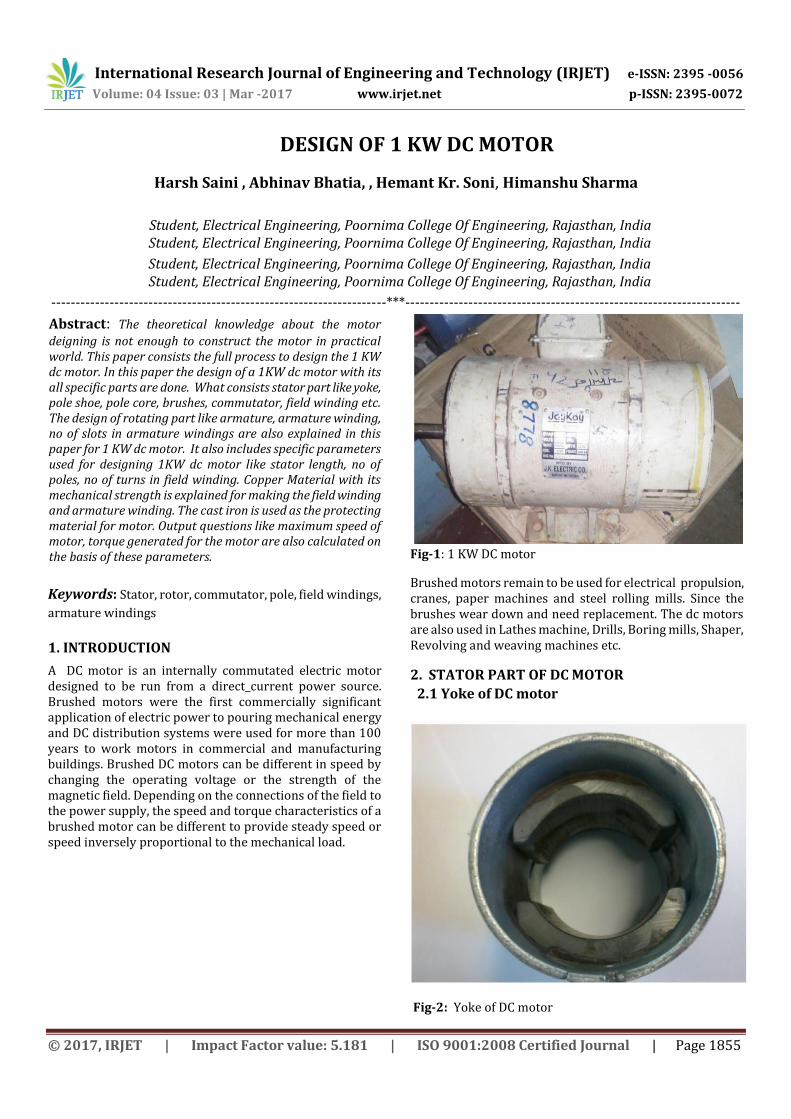
A DC motor is an internally commutated electric motor designed to be run from a direct current power source. Brushed motors were the first commercially significant application of electric power to pouring mechanical energy and DC distribution systems were used for more than 100 years to work motors in commercial and manufacturing buildings. Brushed DC motors can be different in speed by changing the operating voltage or the strength of the magnetic field. Depending on the connections of the field to the power supply, the speed and torque characteristics of a brushed motor can be different to provide steady speed or speed inversely proportional to the mechanical load.
Fig-1: 1 KW DC motor
Brushed motors remain to be used for electrical propulsion, cranes, paper machines and steel rolling mills. Since the brushes wear down and need replacement. The dc motors are also used in Lathes machine, Drills, Boring mills, Shaper, Revolving and weaving machines etc.
2. STATOR PART OF DC MOTOR
2.1 Yoke of DC motor
Fig-2: Yoke of DC motor
International Research Journal of Engineering and Technology (IRJET) e-ISSN: 2395 -0056
Volume: 04 Issue: 03 | Mar -2017 www.irjet.net p-ISSN: 2395-0072
© 2017, IRJET | Impact Factor value: 5.181 | ISO 9001:2008 Certified Journal | Page 1856
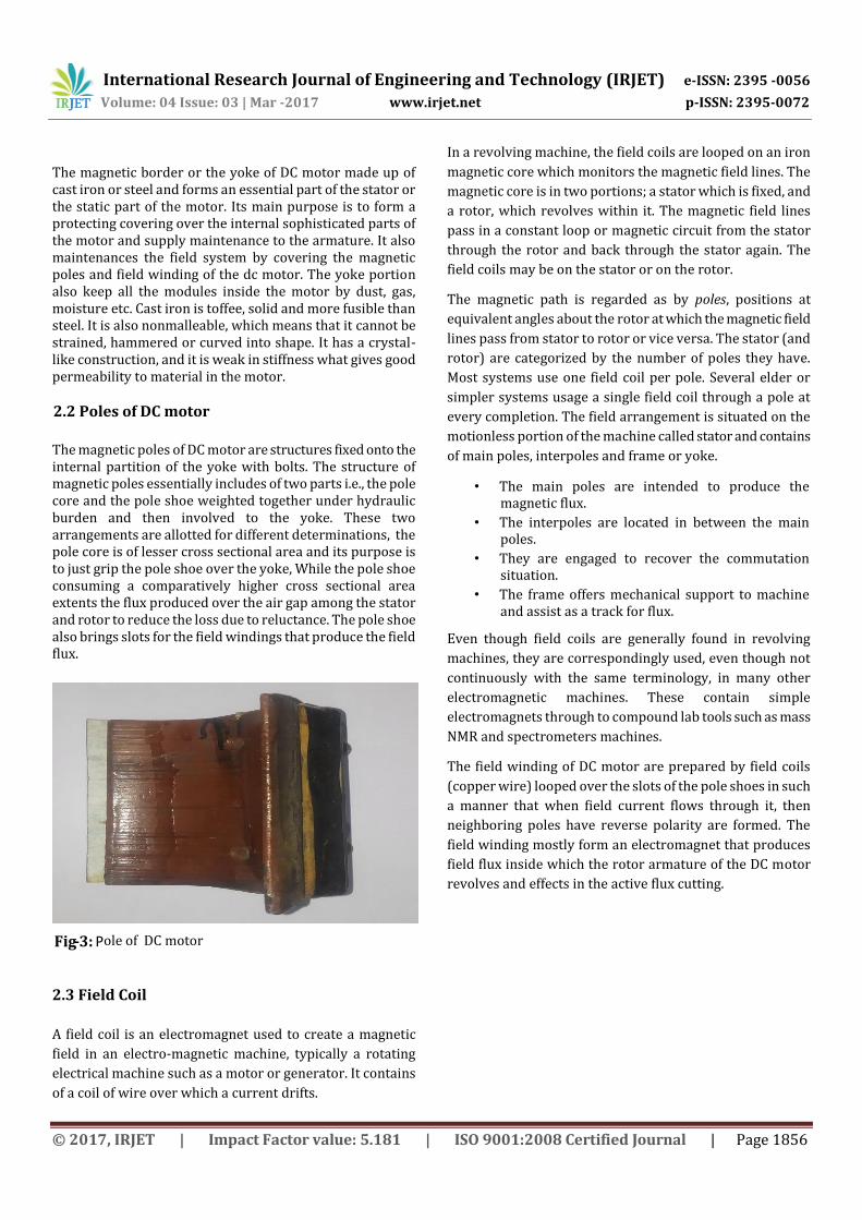
The magnetic border or the yoke of DC motor made up of cast iron or steel and forms an essential part of the stator or the static part of the motor. Its main purpose is to form a protecting covering over the internal sophisticated parts of the motor and supply maintenance to the armature. It also maintenances the field system by covering the magnetic poles and field winding of the dc motor. The yoke portion also keep all the modules inside the motor by dust, gas, moisture etc. Cast iron is toffee, solid and more fusible than steel. It is also nonmalleable, which means that it cannot be strained, hammered or curved into shape. It has a crystal-like construction, and it is weak in stiffness what gives good permeability to material in the motor.
2.2 Poles of DC motor
The magnetic poles of DC motor are structures fixed onto the internal partition of the yoke with bolts. The structure of magnetic poles essentially includes of two parts i.e., the pole core and the pole shoe weighted together under hydraulic burden and then involved to the yoke. These two arrangements are allotted for different determinations, the pole core is of lesser cross sectional area and its purpose is to just grip the pole shoe over the yoke, While the pole shoe consuming a comparatively higher cross sectional area extents the flux produced over the air gap among the stator and rotor to reduce the loss due to reluctance. The pole shoe also brings slots for the field windings that produce the field flux.
2.3 Field Coil
A field coil is an electromagnet used to create a magnetic
field in an electro-magnetic machine, typically a rotating
electrical machine such as a motor or generator. It contains
of a coil of wire over which a current drifts.
In a revolving machine, the field coils are looped on an iron
magnetic core which monitors the magnetic field lines. The
magnetic core is in two portions; a stator which is fixed, and
a rotor, which revolves within it. The magnetic field lines
pass in a constant loop or magnetic circuit from the stator
through the rotor and back through the stator again. The
field coils may be on the stator or on the rotor.
The magnetic path is regarded as by poles, positions at
equivalent angles about the rotor at which the magnetic field
lines pass from stator to rotor or vice versa. The stator (and
rotor) are categorized by the number of poles they have.
Most systems use one field coil per pole. Several elder or
simpler systems usage a single field coil through a pole at
every completion. The field arrangement is situated on the
motionless portion of the machine called stator and contains
of main poles, interpoles and frame or yoke.
• The main poles are intended to produce the magnetic flux.
• The interpoles are located in between the main poles.
• They are engaged to recover the commutation situation.
• The frame offers mechanical support to machine and assist as a track for flux.
Even though field coils are generally found in revolving
machines, they are correspondingly used, even though not
continuously with the same terminology, in many other
electromagnetic machines. These contain simple
electromagnets through to compound lab tools such as mass
NMR and spectrometers machines.
The field winding of DC motor are prepared by field coils
(copper wire) looped over the slots of the pole shoes in such
a manner that when field current flows through it, then
neighboring poles have reverse polarity are formed. The
field winding mostly form an electromagnet that produces
field flux inside which the rotor armature of the DC motor
revolves and effects in the active flux cutting.
Fig - 3: P ole of DC motor

International Research Journal of Engineering and Technology (IRJET) e-ISSN: 2395 -0056
Volume: 04 Issue: 03 | Mar -2017 www.irjet.net p-ISSN: 2395-0072
© 2017, IRJET | Impact Factor value: 5.181 | ISO 9001:2008 Certified Journal | Page 1857
Fig-4: Field winding of DC motor
2.4 Winding Material Used for Field Winding
Coils are naturally looped with coated copper wire, sometimes called magnet wire. The winding substantial must have a low resistance to decrease the power expended through the field coil but more essentially to decrease the unwanted heat formed by ohmic heating. Excess heat in the windings is a common reason of failure. Owing to the increasing price of copper, aluminium windings are gradually used.
An even well material than copper, except for its high cost, would be silver as this has even lower resistivity. Silver has been used in infrequent cases.
3. ROTOR PART OF DC MOTOR
3.1 Armature of dc motor
The armature is the revolving part of a dc machine
• It consists of armature core with slots and armature winding housed in slots.
• The conversion of energy from mechanical to electrical or vice-versa proceeds place in armature.
The armature winding of DC motor is devoted to the rotor or the revolving portion of the machine and thus it is exposed to changing magnetic field in the path of its revolution which straight effects in magnetic losses. For this purpose the rotor is prepared of armature core, that’s made with some low-hysteresis silicon steel lamination, to decrease the magnetic losses alike hysteresis and eddy current loss correspondingly. These laminated steel sheets are arranged together to form the cylinder-shaped construction of the armature core.
Fig-5: Rotor of DC motor The armature core are provided with slots prepared of the
similar material as the core to which the armature winding
prepared with some turns of copper wire scattered
consistently over the whole border of the core. The slot
beginnings a shut with fibrous wedges to inhibit the
conductor from plying out because of the great centrifugal
force formed throughout the revolution of the armature, in
occurrence of supply current and field.
3.2 Armature windings used in motor
DC machines have two general types of double layer
windings. They are
1. Simplex lap winding
2. Simplex wave winding
These two types of windings mostly change from each other
in the following two aspects.
• The number of circuits among the positive and negative brushes, i.e., number of parallel paths.
• The way in which the coil ends are attached to the commutator segments.
In simplex lap winding the amount of parallel paths is equivalent to number of poles, whereas in simplex wave winding the number of parallel paths is two.
In simplex lap winding the finish of a coil is linked to start of
next coil. In simplex wave winding the finish of a coil is
linked to start of a coil which is lying one pitch away from
the finish.
The simplex lap or wave windings are appropriate for most
of the dc machines used for numerous uses. But irregularly
the number of parallel paths has to be better to a worth
International Research Journal of Engineering and Technology (IRJET) e-ISSN: 2395 -0056
Volume: 04 Issue: 03 | Mar -2017 www.irjet.net p-ISSN: 2395-0072
© 2017, IRJET | Impact Factor value: 5.181 | ISO 9001:2008 Certified Journal | Page 1858
more than that delivered by simplex windings. In such cases
the multiplex windings are worked.
When the number of parallel paths in a multiplex winding is
double that of simplex winding it is named duplex winding.
When the number of parallel paths in a multiplex winding is
thrice that of simplex winding it is called triplex winding and
so on.
In common the lap winding and wave winding states to
simplex windings.
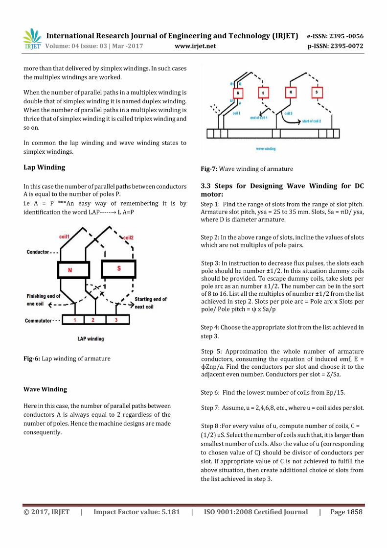
Lap Winding
In this case the number of parallel paths between conductors A is equal to the number of poles P.
i.e A = P ***An easy way of remembering it is by
identification the word LAP-----→ L A=P
Fig-6: Lap winding of armature
Wave Winding
Here in this case, the number of parallel paths between
conductors A is always equal to 2 regardless of the
number of poles. Hence the machine designs are made
consequently.
Fig-7: Wave winding of armature
3.3 Steps for Designing Wave Winding for DC motor:
Step 1: Find the range of slots from the range of slot pitch. Armature slot pitch, ysa = 25 to 35 mm. Slots, Sa = πD/ ysa, where D is diameter armature.
Step 2: In the above range of slots, incline the values of slots which are not multiples of pole pairs.
Step 3: In instruction to decrease flux pulses, the slots each pole should be number ±1/2. In this situation dummy coils should be provided. To escape dummy coils, take slots per pole arc as an number ±1/2. The number can be in the sort of 8 to 16. List all the multiples of number ±1/2 from the list achieved in step 2. Slots per pole arc = Pole arc x Slots per pole/ Pole pitch = ψ x Sa/p
Step 4: Choose the appropriate slot from the list achieved in
step 3.
Step 5: Approximation the whole number of armature conductors, consuming the equation of induced emf, E = ɸZnp/a. Find the conductors per slot and choose it to the adjacent even number. Conductors per slot = Z/Sa.
Step 6: Find the lowest number of coils from Ep/15.
Step 7: Assume, u = 2,4,6,8, etc., where u = coil sides per slot.
Step 8 :For every value of u, compute number of coils, C =
(1/2) uS. Select the number of coils such that, it is larger than
smallest number of coils. Also the value of u (corresponding
to chosen value of C) should be divisor of conductors per
slot. If appropriate value of C is not achieved to fulfill the
above situation, then create additional choice of slots from
the list achieved in step 3.

International Research Journal of Engineering and Technology (IRJET) e-ISSN: 2395 -0056
Volume: 04 Issue: 03 | Mar -2017 www.irjet.net p-ISSN: 2395-0072
© 2017, IRJET | Impact Factor value: 5.181 | ISO 9001:2008 Certified Journal | Page 1859
Step 9: Once the number of coils and slots are confirmed. Approximation the new value of total number of conductors and number of turns per coil. Total armature conductors, Z = Slots x Conductors per slot. Number of turns per coil = Z/2C.
4. COMMUTATOR OF DC MOTOR
The commutator of DC motor is a cylinder-shaped structure
made up of copper sections arranged together, but insulated
from every one through mica. Its foremost purpose as far as
the DC motor is worried is to commute or relay the supply
current from the mains to the armature winding contained
over a rotating structure through the brushes of DC motor.
The commutator is attached on the rotor of a dc machine.
• The commutator and brush arrangement works similar a mechanical dual converter.
• In situation of generator it rectifies the encouraged ac to dc.
• In case of motor it reverses the dc supply to ac. (In motor, the commutator opposites the current through the armature conductors to get unidirectional torque).
Fig-8: Commutator of dc motor
4.1 Brushes of DC motor
Brushes in a dc motor support to join the armature and the
field to the peripheral source. They are mostly manufactured
from graphite, an allotrope of carbon. The most
contemporary motors made today scarcely have brushes.
The main work of brushes to supply current to the coil
through brushes marginally pushed against the commutator.
Fig-9: Brushes used in motor
5. EQUATIONS OF DC MOTOR
5.1 Length of air-gap
• In revolving electrical machines a minor gap is delivered between the rotor and stator to elude the friction between the stationary and rotating portions.
• A greater value of air-gap effects in smaller noise, well cooling, reduced pole face losses, reduced flowing currents and less distortion of field form.
• Also greater air-gap results in greater field mmf which decreases armature reaction.
• In general, mmf essential for air-gap
ATg = 800, 000 Bg Kg lg
. where Kg = 1.15 = gap contraction factor.
• In dc machines the mmf essential for air-
gap is generally taken as 0.5 to 0.7 times the
armature mmf per pole.
• Armature mmf per pole = Iz(Z/2)/p =
IzZ/2p = ac.πD/2p = ac.τ/2
• mmf essential for air-gap in dc machine, ATg = (0.5 to 0.7) x ac. τ/2
International Research Journal of Engineering and Technology (IRJET) e-ISSN: 2395 -0056
Volume: 04 Issue: 03 | Mar -2017 www.irjet.net p-ISSN: 2395-0072
© 2017, IRJET | Impact Factor value: 5.181 | ISO 9001:2008 Certified Journal | Page 1860
• On linking the above calculations we get,
800,000 BgKglg = (0.5 to 0.7) x ac. τ /2
Air - gap length, lg = (0.5 to 0.7) x ac. τ/1600000BgKg = (0.5 to 0.7) x ac. τ /1.6 x 106 BgKg
The usual values of air-gap lies between 0.01 to 0.015
times of pole pitch
5.2 Armature Core Design
• The armature of a dc machine consists of core and winding.
• The armature core is cylindrical in shape with slots on the outer periphery of the armature.
• The core is formed with circular laminations of thickness 0.5 mm.
• The winding is placed on the slots in the armature core.
• The design of armature core involves the design of main dimensions D & L, number of slots, slot dimensions and depth of core.
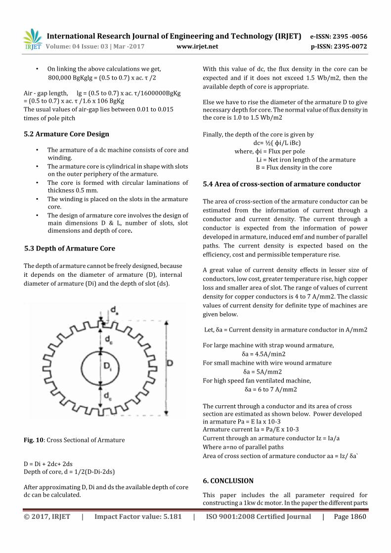
5.3 Depth of Armature Core
The depth of armature cannot be freely designed, because
it depends on the diameter of armature (D), internal
diameter of armature (Di) and the depth of slot (ds).
Fig. 10: Cross Sectional of Armature
D = Di + 2dc+ 2ds Depth of core, d = 1/2(D-Di-2ds)
After approximating D, Di and ds the available depth of core dc can be calculated.
With this value of dc, the flux density in the core can be
expected and if it does not exceed 1.5 Wb/m2, then the
available depth of core is appropriate.
Else we have to rise the diameter of the armature D to give necessary depth for core. The normal value of flux density in the core is 1.0 to 1.5 Wb/m2
Finally, the depth of the core is given by
dc= ½( ɸi/L iBc)
where, ɸi = Flux per pole
Li = Net iron length of the armature B = Flux density in the core
5.4 Area of cross-section of armature conductor
The area of cross-section of the armature conductor can be
estimated from the information of current through a
conductor and current density. The current through a
conductor is expected from the information of power
developed in armature, induced emf and number of parallel
paths. The current density is expected based on the
efficiency, cost and permissible temperature rise.
A great value of current density effects in lesser size of
conductors, low cost, greater temperature rise, high copper
loss and smaller area of slot. The range of values of current
density for copper conductors is 4 to 7 A/mm2. The classic
values of current density for definite type of machines are
given below.
Let, δa = Current density in armature conductor in A/mm2
For large machine with strap wound armature,
δa = 4.5A/min2
For small machine with wire wound armature
δa = 5A/mm2
For high speed fan ventilated machine,
δa = 6 to 7 A/mm2
The current through a conductor and its area of cross section are estimated as shown below. Power developed in armature Pa = E Ia x 10-3 Armature current Ia = Pa/E x 10-3
Current through an armature conductor Iz = Ia/a
Where a=no of parallel paths
Area of cross section of armature conductor aa = Iz/ δa`
6. CONCLUSION
This paper includes the all parameter required for constructing a 1kw dc motor. In the paper the different parts
International Research Journal of Engineering and Technology (IRJET) e-ISSN: 2395 -0056
Volume: 04 Issue: 03 | Mar -2017 www.irjet.net p-ISSN: 2395-0072
© 2017, IRJET | Impact Factor value: 5.181 | ISO 9001:2008 Certified Journal | Page 1861
of motor is explained for design consideration and the materials used for its parts. In this paper the different output equations are also added to make the motor with a specified calculations.
7. REFERENCES 1. L. R. Moskowitz, Permanent Magnet Design and
Application Handbook. Melbourne, FL: Krieger, 1995.
2. P. Beckley, Electrical Steels for Rotating Machines. London, U.K.: IEE, 2002.
3. P. Beckley, Electrical Steels. Newport, U.K.: Eur. Elect. Steels, 2000.
4. K. Yamazaki and H. Ishigami, “Rotor-shape optimization of interiorpermanent-magnet motors to reduce harmonic iron losses,” IEEE Trans.
5. Ind. Electron., vol. 57, no. 1, pp. 61–69, Jan. 2010.
6. J. Pyrhonen, T. Jokinen, and V. Hrabovcova, Design of Rotating Electrical Machines. Chichester, U.K.:
Wiley, 2007