Methods of Dewatering
25
1 CHAPTER ONE INTRODUCTION 1.1 GENERAL Ground water conditions play an important part in the stability of foundations. If the water table lies very close to the base of footings, the bearing capacity and settlement characteristics of the soil would be affected. The level of the water table fluctuates with season. During the end of monsoons, the water table level will be closer to the ground surface as compared to the period just before the monsoons. The difference in levels between the maximum and the minimum may fluctuate from year to year. In many big projects, it is sometimes very essential to know these fluctuations. Piezometers are therefore required to be installed in such areas for measuring the level of water table for one or more years. In some cases clients may demand the depth of water table during the period of site investigation. The depth can be measured fairly accurately during boring operation.. In a fairly draining material such as sand and gravel, the water level returns to its original position in a matter of few minutes or hours, whereas, in soils of low permeability it may take several days. Insuch cases, the water table level has to be located by some reliable method. In some cases, the ground water flows under pressure through a pervious layer of soil confined from its top and bottom between impermeable geological formations. If the water flows from a higher elevation to a lower level, an artesian pressures created and such a ground water is termed as artesian water. It is essential to investigate the possibility of existence of artesian water in a project area. Permeability of soils is another important factor, which needs to be known in many of the major projects. Selection of pumps for pumping out water from excavated trenches or pits depends on the permeability of soils. The settlement and stability of foundations also depend on the permeability of soils. Construction of buildings, powerhouses, dams, locks and many other structures requires excavation below the water table into water-bearing soils. Such excavations require lowering the water table below the slopes and bottom of the excavation to prevent raveling or sloughing of the slope and to ensure dry, firm working conditions for construction operations.Groundwater can be controlled by means of one or more types of dewatering
-
Upload
ajinkya-gaikwad -
Category
Engineering
-
view
1.759 -
download
2
Transcript of Methods of Dewatering
1
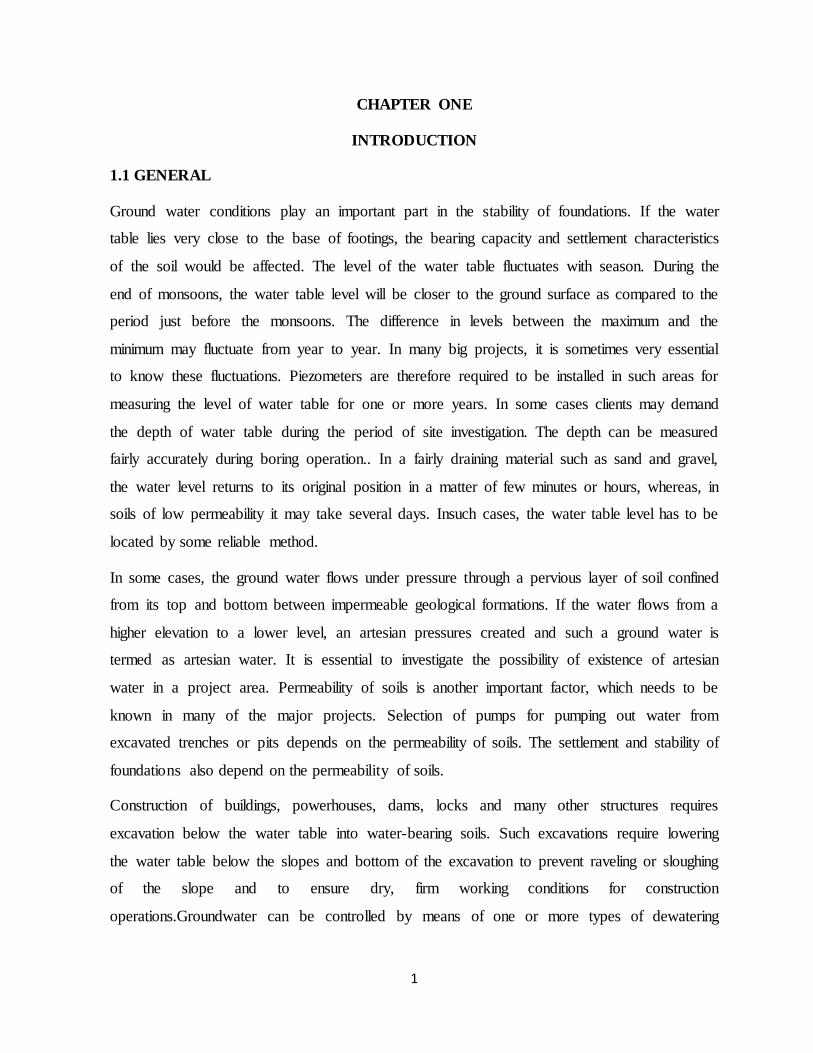
CHAPTER ONE
INTRODUCTION
1.1 GENERAL
Ground water conditions play an important part in the stability of foundations. If the water
table lies very close to the base of footings, the bearing capacity and settlement characteristics
of the soil would be affected. The level of the water table fluctuates with season. During the
end of monsoons, the water table level will be closer to the ground surface as compared to the
period just before the monsoons. The difference in levels between the maximum and the
minimum may fluctuate from year to year. In many big projects, it is sometimes very essential
to know these fluctuations. Piezometers are therefore required to be installed in such areas for
measuring the level of water table for one or more years. In some cases clients may demand
the depth of water table during the period of site investigation. The depth can be measured
fairly accurately during boring operation.. In a fairly draining material such as sand and gravel,
the water level returns to its original position in a matter of few minutes or hours, whereas, in
soils of low permeability it may take several days. Insuch cases, the water table level has to be
located by some reliable method.
In some cases, the ground water flows under pressure through a pervious layer of soil confined
from its top and bottom between impermeable geological formations. If the water flows from a
higher elevation to a lower level, an artesian pressures created and such a ground water is
termed as artesian water. It is essential to investigate the possibility of existence of artesian
water in a project area. Permeability of soils is another important factor, which needs to be
known in many of the major projects. Selection of pumps for pumping out water from
excavated trenches or pits depends on the permeability of soils. The settlement and stability of
foundations also depend on the permeability of soils.
Construction of buildings, powerhouses, dams, locks and many other structures requires
excavation below the water table into water-bearing soils. Such excavations require lowering
the water table below the slopes and bottom of the excavation to prevent raveling or sloughing
of the slope and to ensure dry, firm working conditions for construction
operations.Groundwater can be controlled by means of one or more types of dewatering

2
systems appropriate to the size and depth of the excavation, geological conditions, and
characteristics of the soil.
1.2 OBJECTIVES OF STUDY
1) To know the concept of Dewatering
2) To know the dewatering methods available for construction of dewatering
3) To know which type of dewatering methods are appropriate for various soil conditions.
1.3 DEFINITION
Dewatering means “the separation of water from the soil,” or perhaps “taking the water out of
a particular construction problem completely.” Many excavations are carried below
groundwater level. Techniques for dealing with the problems that result depend on
theexcavation dimensions, the soil type, and the groundwater control requirements, among
otherfactors. The simplest dewatering operations are carried out with little planning Major
operations in difficult conditions require advanced engineering and construction methods.
1.4 GROUND WATER TABLE
Ground water is sub-surface water, but not all sub-surface water is ground water. The upper
surface of ground water is the water table. Below this surface, all the pore spaces and cracks in
sediments and rocks are completely filled (saturated) with water. These saturated layers,
known as the saturated zone (or the phreatic zone), are where ground water occurs. Strictly
speaking only water found in the saturated zone is ground water.
1.5 WATER TABLE LOCATION
Borehole observation is the simplest technique. Boreholes drilled during a subsurface
investigation can be kept open for 24 hours. The level of water is normally determined by
lowering a tape with a float or by an electrical switching device, which is, actuated on contact
with water. In a cohesive soil stratum, the stabilization of water table may take time. In such
situations, the location may be ascertained by adopting the extrapolation method. In this case,
a plot of water level versus time is made and the groundwater level is estimated by
extrapolating the curve until it becomes parallel to the time axis. If several levels are noted at
equal time intervals the following computational method is used.

3
1.6 PURPOSES FOR DEWATERING
1.6.1 During Construction Stage
1) Provide a dry excavation and permit construction to proceed efficiently.
2) Reduce lateral loads on sheeting and bracing in excavations.
3) Stabilize “quick” bottom conditions and prevent heaving and piping.
4) Improve supporting characteristics of foundation materials.
5) Increase stability of excavation slopes and side-hill fills.
6) Cut off capillary rise and prevent piping and frost heaving in pavements.
7) Reduce air pressure in tunneling operations.
1.6.2 Post Construction Stage
1) Reduce or eliminate uplift pressures on bottom slabs and permit economics from the
reduction of slab thicknesses fro basements, buried structures, canal linings, spillways, dry
docks, etc.
2) Provide for dry basements.
3) Reduce lateral pressures on retaining structures.
4) Control embankment seepage in all dams.
5) Control seepage and pore pressures beneath pavements, side-hill fills, and cut slopes.
1.7 PERMEABILITY OF SOIL
The ability of soil to allow the water to flow through it is called Permeability. It is very
important for the structures which are in contact with water e.g. Dams, Bridge, and Canals etc.
Soils have interconnected voids through which water can flow from points of high energy to
points of low energy. It is necessary to estimate the quantity of underground seepage for
investigating problems involving the pumping of water for underground construction, and
making stability analysis of earth dams and earth-retaining structures that are subjected to
seepage forces. Range of permeability for various soils is shown in Table1.1 and fig. 1.1

4
Table 1.1 Range Of Permeability for Various Type of Soil.
Type of Soil Permeability
Coefficient(k)(cm/sec)
Relative Permeability
Coarse gravel Exceeds 10^-1 High
Clean sand 10^-1 to 10^-3 Medium
Dirty sand 10^-3 to 10^-5 Low
Silt 10^-5 to 10^-7 Very low
Clay Less than 10^-7 Impervious
Figure 1.1 Range of Permeability for Various Dewatering Methods

5
CHAPTER TWO
METHODS OF DEWATERING
2.1 INTRODUCTION
Construction dewatering has existed as a specialty industry for a long time. Consequently,
anumber of well established techniques have been developed to lower the ground water table
during excavation. The geology, ground water conditions, and type of excavation all influence
the selection of dewatering technology. The most common methods for dewatering include
sumps, wells and well-points.
1) Sumps provide localized, very shallow dewatering (less than 3 feet) and consist of pumping
from perforated drums or casings in a gravel-filled backhoe pit. Sumps work best in tight,
fine grained soils, or very coarse, boulder deposits.
2) Wells are large-diameter (greater than 6 inches) holes, drilled relatively deep (greater than
10 feet), and contain slotted casings and down hole pumps. Wells work best in soils
consisting of sand, or sand and gravel mixtures and can dewater large areas to great depths.
3) Well-points are small-diameter (less than 6 inches), shallow wells, and are closely spaced
(2 to 10 feet apart). Well-points effectively dewater coarse sands and gravels, or silts and
clays. They have a wide range of applications. However, well-points use a vacuum system
and their depth is limited to about 25 feet. Well-point systems generally cost more than
either sumps or wells, and require near-continual maintenance. A number of other
dewatering techniques are available including ground freezing and electro osmosis.
However, such techniques are very costly and used only for particularly difficult
dewatering applications.
The Available Methods of Groundwater Control Fall into the Following Basic Groups:
1. Surface water control like ditches, training walls, embankments. Simple methods of
diverting surface water, open excavations. Simple pumping equipment.
2. Gravity drainage. Relatively impermeable soils. Open excavations especially on sloping
sites. Simple pumping equipment.
3. Sump pumping
4. Well-point systems with suction pumps.

6
5. Shallow (bored) wells with pumps.
6. Deep (bored) wells with pumps.
7. Eductor system.
8. Drainage galleries. Removal of large quantities of water for dam abutments, cut-offs
landslides etc. Large quantities of water can be drained into gallery (small diameter tunnel)
and disposed of by conventional large – scale pumps.
9. Electro-osmosis. Used in low permeability soils (silts, silty clays, some peats) when no
other method is suitable. Direct current electricity is applied from anodes (steel rods) to
cathodes (well-points, i.e. small diameter filter wells)
Exclusion Methods
1. Ground freezing (ammonium brine refrigeration or liquid nitrogen refrigeration). All types
of saturated soils.
2. Slurry trench cut-off walls with betonies or native clay and Diaphragm concrete walls. All
soils. Curtain walls around excavations with flat buckets.
3. Impervious soil barrier. All soils.Relatively shallow applications (5-6m max.). Backhoes
form the clay filled barriers some distance from the excavation boundaries.
4. Sheet piling. All soils except soils with large boulders.
5. Secant (interlocked) piling or tangent piling with grouting in between. All soils except
boulders.
6. Compressed air. All types of saturated soils and rock. Applications in tunnels, shafts and
caissons.
7. Grouted cut-offs (jet grouting, cementations grouts, chemical grouts etc.)

7
2.2 SUMPS AND SUMP PUMPING
A sump is merely a hole in the ground from which water is being pumped for the purpose of
removing water from the adjoining area as shown in fig.2.1. They are used with ditches
leading to them in large excavations. Up to maximum of 8m below pump installation level; for
greater depths a submersible pump is required. Shallow slopes may be required for
unsupported excavations in silts and fine sands. Gravels and coarse sands are more suitable.
Fines may be easily removed from ground and soils containing large percent of fines are not
suitable. If there are existing foundations in the vicinity pumping may cause settlement of
these foundations. Subsidence of adjacent ground and sloughing of the lower part of a slope
(sloped pits) may occur. The sump should be preferably lined with a filter material which has
grain size gradations in compatible with the filter rules. For prolonged pumping the sump
should be prepared by first driving sheeting around the sump area for the full depth of the
sump and installing a cage inside the sump made of wire mesh with internal strutting or a
perforating pipe filling the filter material in the space outside the cage and at the bottom of the
cage and withdrawing the sheeting. Two simple sumping.
Fig.2.1 Sump Well Method OfDewatering.

8
2.2.1 Advantages of Open Sump and Ditches
1. Widely used method.
2. Most economical method for installation and maintenance.
3. Can be applied for most soil and rock conditions.
4. Most appropriate method in situation where boulders or massive obstructions are met
Within the ground. Greatest depth to which the water table can be lowered by this method
isabout 8 m below the pump.
2.2.2 Disadvantages of Open Sump and Ditches
1. Ground water flows towards the excavation with high head or a steep slope and hence
there is a risk of collapse of sides.
2. In open or timbered excavations there is risk of instability of the base due to upward.
2.3 WELLPOINT SYSTEMS
A well-point is 5.0-7.5 cm diameter metal or plastic pipe 60 cm – 120 cm long which is
perforated and covered with a screen. The lower end of the pipe has a driving head with water
holes for jetting as shown in fig.2.2. Well-points are connected to 5.0-7.5 cm diameter pipes
known as riser pipes and are inserted into the ground by driving or jetting. The upper ends of
the riser pipes lead to a header pipe which, in turn, connected to a pump. The ground water is
drawn by the pump into the well-points through the header pipe and discharged as shown in
fig. 2.3. The well-points are usually installed with 0.75m – 3m spacing. This type of
dewatering system is effective in soils constituted primarily of sand fraction or other soil
containing seams of such materials. In gravels spacing required may be too close and
impracticable. In clays it is also not used because it is too slow. In silts and silt – clay mixtures
the use of well points are aided by upper (0.60m – 0.90m long) compacted clay seals and sand-
filtered boreholes (20cm – 60cm diameter). Upper clay seals help to maintain higher suction
(vacuum) pressures and sand filters increase the amount of discharge.
Filtered boreholes are also functional in layered soil profiles approximate time required for
effective drawdown The header pipe (15-30 cm diameter, connecting all well-points) is
connected to a vacuum (Suction assisted self – priming centrifugal or piston) pump. The well-
points can lower a water level to a maximum of 5.5 m below the centerline of the header pipe.
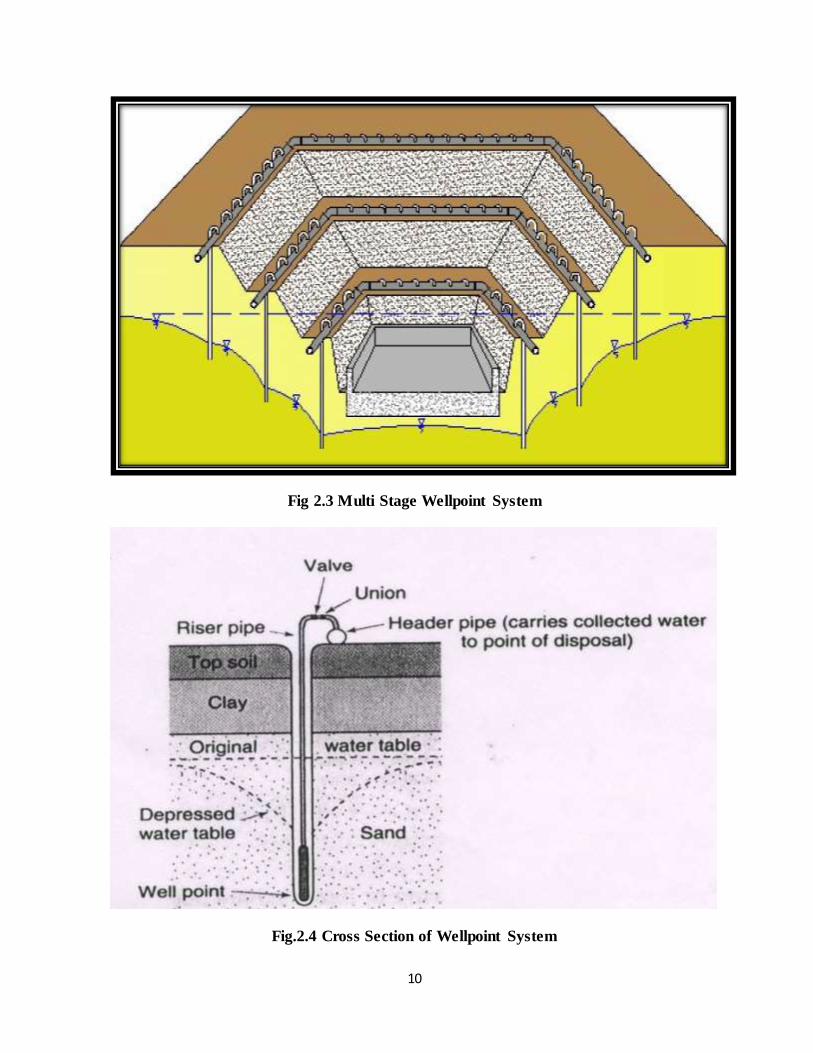
In silty fine sands this limit is 3-4 m. Multiple stage system of well-points are used for

9
lowering water level to a greater depth. Two or more tiers (stages) are used as shown in
fig.2.4. More pumps are needed and due to the berms required the excavation width becomes
wider. A single well-point handles between 4 and 0.6 m3/hr depending on soil type. For a 120
m length (40 at 3 m centers) flowis therefore between 160 and 24 m3/hr. Nomograms for
selecting preliminary wellpoint spacing in clean uniform sand and gravel, and stratified clean
sand and gravel are shown in horizontal well-points are used mainly for pipeline water. They
consist of perforated pipes laid horizontally in a trench and connected to a suitable pump.
Fig 2.2 Single Stage Wellpoint System
10
Fig 2.3 Multi Stage Wellpoint System
Fig.2.4 Cross Section of Wellpoint System

11
2.3.1 Design Considerations of Well-Point System of Dewatering
When designing a well point system, it is necessary to give first consideration tothe physical
conditions of the site to be dewatered.
Following is the list of information to be collected:
a) The physical layout
b) Adjacent areas
c) Soil conditions
d) Permeability of the soil
e) The amount of water to be pumped
f) Depth to imperviousness
g) Stratification
2.3.2 Advantages of Well Point System
a) Installation is very rapid
b) Requires reasonably simple and less costly equipment
c) Water is filtered and carries little or no soil particles.
d) There is less danger of subsidence of the surrounding ground than with open-sump
pumping
2.3.3 Limitations of Well Point System
1) A lowering of about 6 m (20 ft) below pump level is generally possible beyondwhich
excessive air shall be drawn into the system through the joints in the pipes,valves, etc.,
resulting in the loss of pumping efficiency.
2) If the ground is consisting mainly of large gravel, stiff clay or soil containingcobbles or
boulders it is not possible to install well points.

12
Table 2.1 Spacing of Well-points According To Type of Soil
Soil Type Spacing of well-points (in m)
Silty sand 1.5-2.0
Sandy gravel 1.0-1.5
Fine to coarse gravel 0.5-1.0
2.4 EDUCTOR SYSTEM
This system also known as the ‘jet eductor system’ or ‘ejector system’ or ‘eductor wellpoint
system’ is similar to the wellpoint system. Instead of employing a vacuum to draw water to the
well-points, the eductor system uses high pressure water and riser units, each about 30-40mm
in diameter. A high pressure supply main feeds water through a venturi tube immediately
above the perforated well screen, creating a reduction in pressure which draws water through
the large diameter rise pipe. The high pressure main feeds off the return water. The advantage
of the eductor system is that in operating many wellpointsfrom a single pump station, the
water table can be lowered in one stage from depths of 10-45 m. This method becomes
economically competitive at depth in soils of low permeability.
Fig 2.5 Installed EductorWell Point System

13
2.4.1 Working of Eductor Dewatering System
Supply pumps at ground level feed high-pressure water to each Eductor well head via a supply
main. The supply flow passes down the well and through a nozzle and venturi in the Eductor.
The flow of water through the nozzle generates a vacuum in the well and draws in
groundwater. The supply flow and extracted groundwater mix, return to the surface and feed
back to the pumping station via a return main. The return flow is used to prime the supply
pumps and the excess water extracted is discharged by overflow from the priming tank. A
single pumping station can be used to operate up to about 75 Eductor wells installed in an
appropriate array around the works.
2.4.2 Advantages of Eductor Dewatering System
1) They are flexible in level and layout
2) Stable in operation
3) Able to run dry without damage
4) Not limited by depth. Also effective to greater depths
5) Best in low-yielding wells
6) Energy intensive
7) Venturi in base of well creates vacuum
2.5 GROUND FREEZING
The principle of ground freezing is to change the water in the soil into a solid wall of ice. This
wall of ice is completely impermeable. The chemical used for freezing of ground is
ammonium brine refrigeration or liquid nitrogen refrigeration.Ground freezing is used for
groundwater cutoff, for earth support, for temporary underpinning, for stabilization of earth for
tunnel excavation, to arrest landslides and to stabilize abandoned mineshafts. The principals of
ground freezing are analogous to pumping groundwater from wells. To freeze the ground, a
row of freeze pipes are placed vertically in the soil and heat energy is removed through these
pipes. Isotherms (an isotherm is a line connecting locations with equal temperature) move out
from the freeze pipes with time similar to groundwater contours around a well.Once the earth
temperature reaches 32 °F (0 °C), water in the soil pores turns to ice. Then further cooling
proceeds. The groundwater in the pores readily freezes in granular soils, such as sands.

14
For instance, saturated sand achieves excellent strength at only a few degrees below the
freezing point. If the temperature is lowered further, the strength increases marginally. In
cohesive soils, such as clays, the ground water is molecularly bonded at least in part to the soil
particles. If soft clay is cooled down to freezing temperature, some portions of its pore water to
begin to freeze and it causes the clay to stiffen. With further reduction in temperature, more
pore water freezes and consequently more strength gain is achieved. When designing for
frozen earth structures in cohesive soils, it may be necessary to specify substantially lower
temperatures to achieve the required strength, than in cohesion less soils. A temperature of +20
°F may be sufficient in sands, whereas temperatures as low as –20 °F may be required in soft
clays.
The design of a frozen earth barrier is governed by the thermal properties of the underlying
soils and related response to the freezing system. Formation of frozen earth barrier developsat
different rates depending on the thermal and hydraulic properties of each stratum.Typically,
rock and coarse-grained soils freeze faster than clays and silts as shown in fig.2.6.
Fig. 2.6– Formation Of Frozen Earth Barrier In Different Soils

15
Fig. 2.7– Freeze Pipes
When soft clay is cooled to the freezing point, some portion of its pore water begins to freeze
and clay begins to stiffen. If the temperature is further reduced, more of the pore water freezes
and the strength of the clay markedly increases. When designing frozen earth structures in clay
it may be necessary to provide for substantially lower temperatures to achieve the required
strengths. A temperature of +20 °F may be adequate in sands, whereas temperatures as low as
–20 °F may be required in soft clay.
If the heat extraction is continued at a high rate, the thickness of the frozen wall will
expandwith time. Once the wall has achieved its design thickness, the freeze plant is operated
at a reduced rate to remove the heat flowing toward the wall, to maintain the condition as
shown in fig.2.7.
2.5.1 Freezing Applications
The freezing method is remarkably versatile, and with ingenuity it can be adapted to a great
many project conditions. The penetration of a freeze does not vary greatly with permeability,
so it is much more effective as a cutoff than grout. In stratified soils, cutoff by freezing

16
encounters fewer problems than drainage by dewatering. Freezing can perform the dual
function of water cutoff and earth support, eliminating sheeting and bracing.
2.6 DEEP-WELL DEWATERING
Deep well systems consist of one or more individual wells, each of which has its own
Submersible pump at the bottom of the well shaft. Such systems are particularly suitable.
Where large volumes of water in highly permeable sand and gravel areas permitting Rapid
recharging of ground water from surrounding areas exist. The Range of permeability under
which the deep well system is applicable.
2.6.1 Deep Well System
A typical deep well consists of a drilled hole within which is a lower screened casing which
admits water to the pump; an upper casing which prevents soil from reaching the pump and,
within the casing, the pump and its discharge pipe. The discharge pipe supports the pump to
which it is attached. Electrical wiring for the pump motor runs between the discharge pipe and
the casing. The space between the drilled hole and the casing is normally packed with filter
material (for example, coarse sand and/or gravel) to minimize the pumping of solid material
from the soil surrounding the well.
2.6.2 Spacing of deep well point system
Normally, individual wells are spaced at an approximate distance of 15 m (50 feet) apart.
However, depending upon soil conditions and the dewatering plan the spacing may need to be
just a few meters apart.
2.6.3 Dewatering Capacity of Deep Well Point System
Individual well capacities are from 21 to 3000 gallons per minute and with total systems the
capacities can be as high as 60 000 gallons per minute. Deep well pumps can lift water 30 m
(100 feet) or more in a single stage and the variation of the typical deep well system is a
pressure within an aquifer. Deep well points require no pump as the water is forced to the
surface by its own pressure. To boost the water flow a vacuum pump is frequently used.

17
Fig. 2.8 Details of A Deep Well
Fig 2.9 Installed Deep Well Point

18
2.6.4 Design Considerations of Deep Well-Point System of Dewatering
When designing a deep well point system, it is necessary to take into consideration the
Following:
1) The soil investigation report
2) The grain size analysis and permeability tests
3) The hydrology of the area
4) The topography
5) The space limitations of the site and surrounding structure.
6) The projected method of excavation and shoring if any
7) The construction schedule

19
CHAPTER THREE
SELECTION OF DEWATERING SYSTEM.
3.1 INTRODUCTION
The method most suitable for dewatering an excavation depends upon the location, type size,
and depth of the excavation; thickness, stratification, and permeability of the foundation soils
below methods the water table into which the excavation extends or is underlain; potential
damage resulting from failure of the dewatering system; and the cost of installation and of the
system. The cost of a dewatering method or system will depend upon:
(1) Type, size, and pumping requirements of project.
(2) Type and availability of power.
(3) Labor requirements.
(4) Duration of required
The rapid development of slurry cutoff walls has made this method of groundwater control,
combined with a certain amount of pumping, a practical and economical alternative for some
projects, especially those where pumping costs would otherwise be great.
3.2 FACTORS CONTROLLING SELECTION
Where foundations must be constructed on soils below the groundwater level, it will generally
be necessary to dewater the excavation by means of a deep well or Well-point system rather
than trenching and sump pumping, Dewatering is usually essential to prevent damage to
foundation soils caused by equipment operations and sloughing or sliding in of the side slopes.
Conventional deep-well and Well-point systems designed and installed by companies
specializing in this work are generally satisfactory, and detailed designs need not be prepared
by the engineer. However, where unusual pressure relief or dewatering requirements must be
achieved, the engineer should make detailed analyses and specify the dewatering system or
detailed results to be achieved in the contract documents. Where unusual equipment and
procedures are required to achieve desired results, they should be described in detail in the
contract documents.

20
3.2.1 Type of Excavation
Small open excavations, or excavations where the depth of water table lowering is small, can
generally be dewatering most economically and safely by means of a conventional wellpoint
system. If the excavation requires that the water table or artesian pressure be lowered more
than 20 or 30 feet, a system of jet eductor type well-points or deep wells may be more suitable.
Either well-points, deep wells, or a combination thereof can be used to dewater an excavation
surrounded by a cofferdam. Excavations for deep shafts, caissons, or tunnels that penetrate
stratified pervious soil or rock can generally best be dewatered with either a deep-well system
(with or without an auxiliary vacuum) or a jet eductor wellpoint system depending on the soil
formation and required rate of pumping, but slurry cutoff walls and freezing should be
evaluated as alternative procedures. Other factors relating to selection of a dewatering system
are interference of the system with construction operations, space available for the system,
sequence of construction operations, durations of dewatering, and cost of the installation and
its operation. Where groundwater lowering is expensive and where cofferdams are required,
caisson construction may be more economical. Caissons are being used more frequently, even
for small structures.
3.2.2 Geological and Soil Conditions
The geologic and soil formations at a site may dictate the type of dewatering or drainage
system. If the soil below the water table is a deep, more or less homogeneous, free-draining
sand, it can be effectively dewatered with either a conventional well or wellpoint system. If, on
the other hand, the formation is highly stratified, or the saturated soil to be dewatered is
underlain by an impervious stratum of clay, shale, or rock, well-points or wells on relatively
close centers may be required. Where soil and groundwater conditions require only the relief
of artesian pressure beneath an excavation, this pressure relief can be accomplished by means
of relatively few deep wells or jet eductor well-points installed around and at the top of the
excavation. (a) If an aquifer is thick so that the penetration of a system of well-points is small,
the small ratio of screen length to aquifer thickness may result in relatively little drawdown
within the excavation, even though the water table is lowered 15 to 20 feet at the line of well-
points. For deep aquifers, a deep-well system will generally be more applicable, or the length

21
of the well-points should be increased and the well-points set deep and surrounded with a
high-capacity filter. On the other hand, if the aquifer is relatively thin or stratified well-points
may be best suited to the situation. (b) The perviousness and drainability of a soil or rock may
dictate the general type of a dewatering system to be used for a project. A guide for the
selection of a dewatering system related to the grain size of soils is presented in figure 2-12.
Some gravels and rock formations may be so permeable that a barrier to flow, such as a slurry
trench, grout curtain, sheet pile cutoff, or freezing, may be necessary to reduce the quantity of
flow to the dewatering system to reasonable proportions. Clean, free draining sands can be
effectively dewatered by wells or well-points. Drainage of sandy silts and silts will usually
require the application of additional vacuum to well or wellpoint dewatering systems, or
possibly the use of the electroosmotic method of dewatering where soils are silty or clayey.
However, where thin sand layers are present, special requirements may be unnecessary.
Electroosmosis should never be used until a test of a conventional system of well- points,
wells with vacuum or jet eductor well-points has been attempted.
3.2.3 Depth of Groundwater Lowering
The magnitude of the drawdown required is an important consideration in selecting a
dewatering system. If the drawdown required is large, deep wells or jet eductor well-points
may be the best because of their ability to achieve large drawdowns from the top of an
excavation, whereas many stages of well-points would be required to accomplish the same
drawdown. Deep wells can be used for a wide range of flows by selecting pumps of
appropriate size, but jet eductor well-points are not as flexible. Since jet eductor pumps are
relatively inefficient, they are most applicable where well flows are small as in silty to fine
sand formations.
3.2.4 Reliability Requirements
The reliability of groundwater control required for a project will have a significant bearing on
the design of the dewatering pumps, power supply, and standby power and equipment. If the
dewatering problem is one involving the relief of artesian pressure to prevent a “blowup” of
the bottom of an excavation, the rate of water table rebound, in event of failure of the system,
may be extremely rapid. Such a situation may influence the type of pressure relief system

22
selected and require inclusion of standby equipment with automatic power transfer and starting
equipment.
3.2.5 Required Rate of Pumping
The rate of pumping required to dewater an excavation may vary from 5 to 50,000 gallons per
minute or more. Thus, flow to a drainage system will have an important effect on the design
and selection of the wells, pumps, and piping system. Turbine or submersible pumps for
pumping deep wells are available in sizes from 3 to 14 inches with capacities ranging from 5
to 5000 gallons per minute at heads up to 500 feet. Wellpoint pumps are available in sizes
from 6 to 12 inches with capacities ranging from 500 to 5000 gallons per minute depending
upon vacuum and discharge heads. Jet eductor pumps are available that will pump from 3 to
20 gallons per minute for lift up to 100 feet. Where soil conditions dictate the use of vacuum
or electroosmotic wellpoint systems, the rate of pumpage will be very small. The rate of
pumpage will depend largely on the distance to the effective source of seepage, amount of
drawdown or pressure relief required, and thickness and perviousness of the aquifer through
which the flow is occurring.
3.2.6 Intermittent Pumping
Pumping labor costs can occasionally be materially reduced by pumping a dewatering system
only one or two shifts per day. While this operation is not generally possible, nor
advantageous, it can be economical where the dewatered area is large; subsoils below subgrade
elevation are deep, pervious, and homogeneous; and the pumping plant is oversize. Where
these conditions exist, the pumping system can be operated to produce an abnormally large
drawdown during one or two shifts. The recovery during nonpumping shifts raises the ground
water level, but not sufficiently to approach subgrade elevation. This type of pumping plant
operation should be permitted only where adequate piezometers have been installed and are
read frequently.
3.2.7 Effect of Ground Water Lowering on Adjacent Structures and Wells
Lowering the groundwater table increases the load on foundation soils below the original
groundwater table. As most soils consolidate upon application of additional load, structures
located within the radius of influence of a dewatering system may settle. The possibility of

23
such settlement should be investigated before a dewatering system is designed. Establishing
reference hubs on adjacent structures prior to the start of dewatering operations will permit
measuring any settlement that occurs during dewatering, and provides a warning of possible
distress or failure of a structure that might be affected. Recharge of the groundwater, as
illustrated in figure 2-13, may be necessary to reduce or eliminate distress to adjacent
structures, or it may be necessary to use positive cutoffs to avoid lowering the groundwater
level outside of an excavation. Positive cutoffs include soil freezing and slurry cutoff
techniques. Observations should be made of the water level in nearby wells before and during
dewatering to determine any effect of dewatering. This information will provide a basis for
evaluating any claims that may be made.
3.2.8 Dewatering Cutoffs and Other Procedures
While dewatering is generally the most expeditious and economical procedure for controlling
water, it is sometimes possible to excavate more economically in the wet inside of a cofferdam
or caisson and then seal the bottom of the excavation with a tremie seal, or use a combination
of slurry wall or other type of cutoff and dewatering. Where subsurface construction extends to
a considerable depth or where high uplift pressures or large flows are anticipated, it may
occasionally be advantageous to: substitute a caisson for a conventional foundation and sink it
to the design elevation without lowering the groundwater level; use a combination of’concrete
cutoff walls constructed in slurry-supported trenches, and a tremied concrete foundation slab,
in which case the cutoff walls may serve also as part of the completed structure; use large
rotary drilling machines for excavating purposes, without lowering the groundwater level; or
use freezing techniques. Cofferdams, caissons, and cutoff walls may have difficulty
penetrating formations containing numerous boulders. Foundation designs requiring
compressed air will rarely be needed, although compressed air may be economical or
necessary for some tunnel construction work.

24
CHAPTER FOUR
CONCLUSION
The concept of dewatering, purpose of dewatering, various methods of dewatering
andselection of method of dewatering for various types of soil strata and according to
permeability of soil are studied.The selection of method of dewatering according to suitability
of ground is as shown in Table 3.1.
Table 3.1 Various Methods with Their Suitability
Method of Dewatering Suitability of Soil
Sump pumping
Gravel or well graded sandy gravel, partially
cemented material , porous rock formation etc
Well point systems Sandy soilDrawdown limit 15 ft
Ejector system
Fine sand conditionDewater up to depth of
100 ft
Ground freezing
groundwater cutoff, stabilization of earth for
tunnel excavation,arrest landslides and to
stabilize mineshafts
Deep (bored) wells
Artesian waterPumping capacity (3000 to
60,000 gallons/min)Dewater up to depth of
300 ft
25
REFERENCES
1) Mansur, C.I. and Kaufman R.I. (1962),” Dewatering, in Foundation Engineering”, pp.241-
350.
2) Powers, J.P. (1992), “Construction Dewatering”, 2nd ed. John Wiley and Sons Inc., pp 1-
17.
3) Quinion, D.W. and Quinion, G.R.(1987), “Control of Groundwater”, ICE Works
Construction Guides, Thomas Telford Pub.Co., London., pp 113-129
4) Teng, V.C.(1962) “Foundation Design”,Prentice-Hall, IAC,Englewood Cliffs, N.J., pp 318-
332