MedelecSynergy - Shopify...SYNERGY USER MANUAL viii Using this Manual This user manual is intended...
230
MedelecSynergy Multimedia EMG Notebook, Tower and Suite User Manual 035W001B Vs8.0
Transcript of MedelecSynergy - Shopify...SYNERGY USER MANUAL viii Using this Manual This user manual is intended...

MedelecSynergyMultimedia EMG
Notebook, Tower and SuiteUser Manual
035W001B Vs8.0


Oxford Instruments Medical LtdManor Way, Old WokingSurrey, GU22 9JU, UKTel: +44 (0)1483 770331Fax: +44 (0)1483 727193E-Mail: [email protected]
www.oxford-instruments.com
!
CopyrightAll rights reserved. This manual contains proprietary information, which is protected by copyrightand may not be copied in whole or in part except with the prior written permission of OxfordInstruments Medical Ltd. The copyright and the foregoing restrictions on the copyright use extendto all media in which this information may be preserved.
This copy of the User Manual shall be used only in accordance with the conditions of sale of OxfordInstruments Medical Ltd or its distributors.
Oxford Instruments Medical Ltd makes no representations or warranties of any kind whatsoeverwith respect to this document. Oxford Instruments Medical Ltd disclaims all liabilities for loss ordamage arising out of the possession, sale or use of this document.
Medelec and TECA are registered trademarks of Oxford Instruments Medical Ltd in the UK andother countries.
This product complies with the provisions of the Medical Device Directive (93/42/EEC)
FRANCE ITALYOxford Instruments SARLDomaine Technologique de SaclayBátiment Ariane4 rue René Razel91892 SACLAY CedexTel: +33 (1) 69 85 25 00Fax:+33 (1) 69 85 25 09E-Mail: [email protected]
Oxford Instruments Medical SpaVia Leone Tolstoi, 8620098 San Giuliano MilaneseMilanoTel: +39 (0)2 982 531Fax:+39 (0)2 982 41407E-Mail: [email protected]
GERMANY SPAINOxford Instruments Medical GmbHOtto-von-Guericke-Ring 1065205 WiesbadenPostfach 4509, D-65035 WiesbadenTel: +49 (0)6122 937-0Fax: +49 (0)6122 937-100E-Mail: [email protected]
Oxford Instruments Medical SAAvda. Mata Pinõnera 228700 San Sebastian de los ReyesMadridTel: +34 (91) 653 8198/ 8387/ 8398Fax: +34 (91) 654 6794E-Mail: [email protected]
NETHERLANDS BELGIUMOxford Instruments Medical NVAvelingen West 14202 MS GorinchemTel: + 31 (0) 183 692111Fax: + 31 (0) 183 6 92119E-Mail: [email protected]
Oxford Instruments Medical NVMolenberglei 21B-2627 SchelleTel: + 32 (0) 3 880 82 80Fax: + 32 (0) 3 844 78 42E-Mail: [email protected]


TECASynergyMultimedia EMG
Notebook, Tower and SuiteUser Manual
035W001B Vs8.0


Oxford Instruments Medical Inc.12 Skyline Drive, Hawthorne,New York 10532-2133, USA
Oxford Instruments Medical LtdManor Way, Old Woking,Surrey, GU22 9JU, UK
Tel: +1 914 593 71001-800 438-8322
Fax: +1 914 593 7290E-Mail: [email protected]
Tel: +44 (0)1483 770331Fax: +44 (0)1483 727193E-Mail: [email protected]
www.oxford-instruments.com
Copyright
All rights reserved. This manual contains proprietary information, which is protected bycopyright and may not be copied in whole or in part except with the prior written permissionof Oxford Instruments Medical Ltd. The copyright and the foregoing restrictions on thecopyright use extend to all media in which this information may be preserved.
This copy of the User Manual shall be used only in accordance with the conditions of sale ofOxford Instruments Medical Ltd or its distributors.
Oxford Instruments Medical Ltd makes no representations or warranties of any kindwhatsoever with respect to this document. Oxford Instruments Medical Ltd disclaims allliabilities for loss or damage arising out of the possession, sale or use of this document.
Medelec and TECA are registered trademarks of Oxford Instruments Medical Ltd in the USA.
Caution:Federal law restricts this device to sale by, or on the order of a physician

SYNERGY USER MANUAL
ii
ContentsUsing this Manual ...................................................................viiiSafety and symbols.................................................................... ixSafety considerations...........................................................................ix
Caution and warnings....................................................................................xResponsibility of the manufacturer ...............................................................xDisposal of equipment..................................................................................xiElectrical interference suppression...............................................................xiSources of artefact.......................................................................................xii
Symbols and their definition ............................................................ xiiiInformation.................................................................................................xiiiConnections.................................................................................................xvSwitches ....................................................................................................xviiWarning Symbols......................................................................................xvii
1: Overview of the system.......................................................... 1The System and its parts.......................................................................1
Components of the Synergy Notebook .........................................................4Components of the Synergy Tower...............................................................6Components of the Synergy Suite .................................................................8The Patient Interface Unit .............................................................................9Footswitch...................................................................................................11Deluxe Stimulator Probe.............................................................................12
Using Synergy.....................................................................................14Logging onto the system .............................................................................14Components of the GUI ..............................................................................15Opening and closing folders........................................................................16Using Electronic Mail .................................................................................16Getting support............................................................................................16
Synergy Reader Software ...................................................................17
Configuring the System......................................................................18
The Patient Database .........................................................................19
The Tests .............................................................................................20
Generating Reports.............................................................................21
2: Handling Patient Information ............................................ 23Entering and saving patient information...........................................23
Entering and saving a new patient...............................................................24Entering and saving visit details..................................................................25
Retrieving existing patient information .............................................27

INTRODUCTION
iii
Recalling a patient.......................................................................................27Deleting a patient ........................................................................................27
Transferring patient information between Synergy systems.............28Transferring patient data between host and satellite....................................28Using Transfer to transfer patient data between systems ............................28Using Copy to transfer patient data between systems .................................29Completing the Transfer..............................................................................30
Reviewing results and reports for an existing patient .......................31Recalling an existing patient .......................................................................31Opening the Test Catalog............................................................................31Recalling results using the Test Catalog .....................................................33Viewing results in the Test Catalog.............................................................33Deleting results............................................................................................33
Searching for patient information .....................................................35Searching on patient details.........................................................................35Clearing the Search Criteria dialog box ......................................................35Cancelling a search......................................................................................35
Saving and loading patient and report data to file ............................36Saving patient and report data to file...........................................................36Loading patient and report data from File ...................................................37
3: Generating reports .............................................................. 39Overview..............................................................................................39
Obtaining a report online ...................................................................40Selecting an online report............................................................................41Viewing a report..........................................................................................41Adding comments .......................................................................................41Recompiling a report...................................................................................41
Recalling a report ...............................................................................43Opening a report in Microsoft Word...........................................................43Opening a report in MedPad .......................................................................43Editing and saving a report using MedPad..................................................43
Customising the report layout ............................................................44Selecting and defining a header file ............................................................45Selecting and defining a signature file ........................................................46Defining the report sequence and inserting page breaks .............................47Defining Test Report settings......................................................................47
Printing a report .................................................................................48
4: Configuring the system ....................................................... 49System configuration..........................................................................49
Defining the host and satellite............................................................50Defining a system as a host .........................................................................50

SYNERGY USER MANUAL
iv
Defining a system as a satellite ...................................................................50Configuring an E-mail program ..................................................................51Selecting a Notch Filter Setting ..................................................................51Configuring Patient Demographics.............................................................52Setting up a new user ..................................................................................52Editing a user's set-up .................................................................................53Deleting a user ............................................................................................54
User Configuration.............................................................................55Changing your User Set-up.........................................................................55Changing a password ..................................................................................56Changing paths............................................................................................56Defining a muscle list..................................................................................57
Network Configuration ......................................................................58Setting up a shared network database..........................................................59Setting up configuration information ..........................................................59Setting up users to share data ......................................................................59Sharing existing data on a local drive .........................................................60
5: Configuring protocols.......................................................... 61Introduction ........................................................................................61
On-line configuration.........................................................................61Change trace sensitivity ..............................................................................62Change trace duration .................................................................................62
Protocol Configuration Wizard..........................................................63Entering the Protocol Configuration Wizard...............................................63Editing an existing protocol ........................................................................64Creating a new protocol ..............................................................................64Acquisition set-up .......................................................................................65Electrical Stimulator Set-up ........................................................................69Protocol Table set-up ..................................................................................70Channel Mapping and Trace Depth set-up..................................................71
6: The tests ................................................................................ 73Using the tests .....................................................................................73
The typical test procedure ...........................................................................74
Selecting the test .................................................................................75
Selecting a protocol ............................................................................75
Motor NCS Test ..................................................................................76Clinical Overview .......................................................................................76Running the Motor NCS test.......................................................................76
Sensory NCS Test ...............................................................................83Clinical Overview .......................................................................................83Running the Sensory NCS test ....................................................................83

INTRODUCTION
v
F-Wave Test ........................................................................................89Clinical Overview .......................................................................................89Running the F-Wave test.............................................................................89
H-Reflex Test ......................................................................................94Clinical Overview .......................................................................................94Running the H-Reflex test...........................................................................94
Needle EMG Test................................................................................97Clinical Overview .......................................................................................97Running the Needle EMG test.....................................................................97
Repetitive Nerve Stimulation Test ....................................................104Clinical Overview .....................................................................................104Running the Repetitive Nerve Stim test ....................................................104
Blink Reflex Test ..............................................................................110Clinical Overview .....................................................................................110Running the Blink Reflex test ...................................................................110
Sympathetic Skin Response Test ......................................................114Running the Sympathetic Skin Response Test ..........................................114
Interference Pattern Analysis Test...................................................115Clinical Overview .....................................................................................115Running the Interference Pattern Analysis test .........................................117
Multi-MUP Analysis Test .................................................................120Clinical Overview .....................................................................................120Running the Multi-MUP Analysis Test.....................................................122
Single Fibre Jitter Test .....................................................................126Clinical Overview .....................................................................................126Running the SFJ Test (Volitional).............................................................126Running the SFJ Test (Stimulated) ...........................................................131
Fibre Density Analysis Test..............................................................137Clinical Overview .....................................................................................137Running the Fibre Density Analysis Test..................................................137
Macro EMG Test ..............................................................................140Clinical Overview .....................................................................................140Running the Macro EMG Test ..................................................................140
Trace analysis and display................................................................144Selecting traces..........................................................................................144Moving traces............................................................................................145Superimposing traces ................................................................................145Automatic marker placement ....................................................................145Manual marking of traces..........................................................................146Change trace sensitivity.............................................................................147Change trace duration................................................................................147Compare ....................................................................................................147

SYNERGY USER MANUAL
vi
Trace arithmetic ........................................................................................148Split sensitivity..........................................................................................149Using the full trace area ............................................................................149Trace area setup ........................................................................................149
Configuring and displaying results..................................................151Results Table.............................................................................................151Result Mode ..............................................................................................151Reference Values ......................................................................................152Configuring the Results Table ..................................................................153Setting up custom results ..........................................................................155Temperature probe ....................................................................................156Displaying the full Results Screen ............................................................156
Appendix A Installation & Maintenance ................................ 1Installation............................................................................................1
WARNING ...................................................................................................1Checks...........................................................................................................1Environment..................................................................................................1Power supply connections.............................................................................2Connecting the equipment.............................................................................7Cables............................................................................................................7Connecting other electrical equipment..........................................................8Switching on ...............................................................................................19Switching off...............................................................................................19Special instructions for use .........................................................................20Electrical stimulating electrodes .................................................................21Stimulators ..................................................................................................22Footswitch...................................................................................................23Printer..........................................................................................................23
Maintenance .......................................................................................24After-sales service support ..........................................................................24Maintenance of the instrument....................................................................24Cleaning ......................................................................................................24
Electrodes............................................................................................25Electrode kit supplied by the Synergy manufacturer ..................................25
Appendix B Interface Connections........................................... 1Signal Cable ..................................................................................................1Connectors on Notebook PC and PC Tower .................................................1Connectors on PIU ........................................................................................1
Appendix C Technical Specifications....................................... 1Amplifiers and Filters ...................................................................................1Data Acquisition and Display .......................................................................1Electrical Stimulator .....................................................................................1Dimensions (Patient Interface Unit)..............................................................2Power Requirements .....................................................................................2

INTRODUCTION
vii
ISO800 Mains Isolating Transformer............................................................2Safety Standards............................................................................................3EMC Standard...............................................................................................3Quality Standards ..........................................................................................3
Appendix D Assembling the Notebook Stand ......................... 1Assembly instructions ...........................................................................1
Appendix E Cable management for the Tower....................... 1

SYNERGY USER MANUAL
viii
Using this ManualThis user manual is intended to be read by anyone who is to useSynergy Notebook, Synergy Tower or Synergy Suite.
Immediately after this section are notes on safety considerationsand a list of the symbols used in Synergy. Then the manual isstructured in chapters as follows:
Chapter 1 Overview of the system illustrates and describes theSynergy and its parts; explains briefly how basically to use thesystem; outlines the basic features of the system.
Chapter 2 Handling patient information describes how toenter, save and retrieve patient details, review patient results andreports and search for patient information, and how to transferpatient information between the Synergy systems
Chapter 3 Generating reports describes how to obtain reportson-line, recall reports and print them, and customising the reportlayout.
Chapter 4 Configuring the system describes how to configuresuch elements as database paths, user set-up and muscle lists.Some information in this chapter is for administrators only.
Chapter 5 Configuring protocols describes how to configureon-line, and how to use the Protocol Configuration Wizard.
Chapter 6 The tests describes all the tests in detail and how torun them; selecting and marking traces; configuring anddisplaying results.
The Appendices cover installation and maintenance of thesystem; interface connections and full technical specification ofthe system.

INTRODUCTION
ix
Safety and symbols
Safety considerationsSynergy complies with EN 60601-1, the European standard forsafety for medical electrical equipment:
For type of protection against electrical shock: Class 1
For degree of protection against electrical shock: Type BF
For degree of protection against harmful ingress of liquid:Ordinary (no protection)
For the mode of operation: Continuous
For the degree of safety of application in the presence of aflammable anaesthetic mixture with air or with oxygen or nitrousoxide: Not suitable
Synergy also complies with:
UL2601-1, the American standard for safety for medicalelectrical equipment
CAN/CSA22.2 No.601.1, the Canadian standard for safety formedical electrical equipment
EN60601-1-1, the European standard for safety for medicalelectrical systems
EN 60601-1-2, the European standard for electromagneticcompatibility requirements for medical electrical equipment
EN60601-2-40, the European standard specifying particularsafety requirements for electromyographs and evoked responseequipment
_____________________
Synergy bears the CE Mark - to show compliance with theEuropean Medical Device Directive (93/42/EEC).
Synergy is designed and manufactured under approved QualityManagement Systems:
EN 29001/ISO 9001:1994, Quality System Standard

SYNERGY USER MANUAL
x
EN 46001:1994, Quality System Standard application tomanufacture medical devices
Caution and warnings1. U.S. Federal law restricts this device to sale by or on the
order of a physician, or other licensed practitioner.
2. It should be noted that it is the responsibility of the user toensure that conformance to the Type BF patient isolationrequirements of EN60601-1, UL2601-1 and CAN/CSA22.2No.601.1 is maintained when patient connected equipment oraccessories not supplied by Oxford Instruments Medical Ltdare used with Oxford Instruments Medical Ltd equipment.
3. If any mains powered equipment, for example printers, videomonitors or other medical equipment, is to be connected toSynergy to form a medical electrical system then therequirements of standard EN60601-1-1 (Medical ElectricalEquipment, Part 1. General requirements for safety, Section1.1 Collateral standard: Safety requirements for medicalelectrical systems) must be complied with to ensure patientand operator safety is maintained.
4. There are no user serviceable parts inside the instrument.Only appropriately trained and qualified personnel shouldadjust, maintain or repair the instrument when it is connectedto the electricity supply. The instrument must bedisconnected from the electricity supply first, before anycover is removed.
Responsibility of the manufacturerOxford Instruments Medical Ltd and our distributors considerthemselves responsible for the effects on safety, reliability andperformance of the equipment only if:
• assembly operations, extensions, readjustments,modifications, or repairs are carried out by personsauthorised by them
• the electrical installation of the relevant room complies withthe appropriate requirements
• the equipment is used in accordance with the instructions foruse
Full compliance of this product cannot be ensured unless allcomponents (leads etc.) are provided by Oxford InstrumentsMedical Limited.

INTRODUCTION
xi
Disposal of equipment When the equipment comes to the end of its operating life, itshould be disposed of in accordance with local waste disposalregulations. Advice on this can usually be obtained from the localwaste regulation authority which is typically to be found withinthe local government office.
Electrical interference suppression These notes are intended as a guide to the location andsuppression of electrical interference. This may affect apparatusinvolving the detection and analysis of signals of a few microvoltsin the frequency range DC to 20kHz, such as forElectroencephalographs (EEG) or Electromyographs (EMG) andEvoked Potential (EP) Recording Systems.
1. 50Hz/60Hz magnetic field from power transformers,induction motors etc.
The only practical protection from this type of interference is theavoidance of loops in the pick-up circuits of the EEG or EMG/EP,since the magnitude of the interfering voltages is directlyproportional to the area enclosed by any such loop.
2. Magnetic field from staff location systems using inductiveloops
This type of interference is of an intermittent character and maybe serious where the inductive loop runs alongside the wall of theexamination room and where the transmitted frequencies fallwithin the pass band of the EEG or EMG/EP.
Most modern staff location systems now use frequencies above20kHz and should, therefore, cause minimum interference unlessthe loop is very close to the EEG or EMG/EP.
3. 50Hz/60Hz electrostatic field from unshielded conductors,lamps etc.
This type of interference is possibly the simplest to locate andcorrect. Any conductor of supply frequency not covered by anearthed metal screen is a potential source of interference. Obvioussources are flexible cables to desk lamps and X-ray viewingboxes, unshielded fluorescent tubes and filament lamps.
It is important that all encasing metalwork of electrical equipmentbe securely bonded electrically to the local circuit earth.

SYNERGY USER MANUAL
xii
4. HF interference from short-wave diathermy, radioambulances, television and sound broadcasting
This class of interference is the most difficult to track down to itssource and by far the most difficult to eliminate.
Short-wave diathermy is easily the most frequent source of HFinterference, particularly in or near a physical medicinedepartment or operating theatre.
The interference may reach the EEG or EMG/EP via a number ofpaths falling into two main categories: (1) Conducted and (2)Radiated.
Conducted HF interference is found on the mains supply. Thiskind of interference on modern equipment is eliminated byefficient mains filtering.
Radiated interference is transmitted through the air and emittedeither from poorly screened electrical equipment or other sourcessuch as radio and TV transmitters and hospital paging systems.In severe cases of this kind, a screened enclosure is essential.
Sources of artefact The following list shows some of the more usual causes ofcorruption of the signal that Synergy has to process.Audio feedbackBroken electrode lead wire including ground electrode wireDiathermyDirty electrodesElectrode lead wire movementElectronic dimmersExcessive low or high power-line voltageFluorescent lightsIgnition noiseIncorrect electrode connection to apparatusIntermittent power-line loadMicrophonyMultiple grounds in the screened roomPick-up from monitor screensPoor apparatus groundPoor ground electrode locationPoorly shielded printersPower cables near patient not unplugged at wall socketRadio and TVUngrounded observersUngrounded wheelchair or table

INTRODUCTION
xiii
Symbols and their definitionNote: Some symbols are used only on Synergy Tower or only onSynergy Notebook. Some symbols will not appear on your unit if they arereplaced by text in your own language.
Information
! Refer to the appropriate pages of this manual forinformation
! Warning that the unit contains high voltage partsinside
" Preamplifier
# Stimulus
$$$$ Stimulus duration
#/s Stimulus repetition rate
% Audio signal
& Display Sensitivity
' Sweep Duration
Fn Function

SYNERGY USER MANUAL
xiv
+ Trigger - rising edge
-
Trigger - falling edge
"""" Equipotential earth terminal
# Isolating transformer
M( Next store
M+ Acquire
" Double arrow head – continuous (Acquire)
# Single arrow head – momentary (Acquire)
M- Erase stores
) Direct current (dc)
*+ Alternating current (ac)
$ Risk of explosion – do not use in the presence ofinflammable anaesthetics
" Stimulus duration increase/decrease
" Rotate clockwise to increase

INTRODUCTION
xv
Connections
,+ The Type BF symbol is placed adjacent toconnectors used for Type BF floating patientapplied parts
- Input
. Output
$$$$
External printer interface
%
Footswitch
&/!
External keyboard / Mouse
'
Patient ground
(
Stimulus Probe
)
Universal Serial Bus
*
Communications Port

SYNERGY USER MANUAL
xvi
+
Temperature Probe
, External Monitor

INTRODUCTION
xvii
Switches
/ OFF (Mains supply)
0 ON (Mains supply)
-
Amplifier OFF
.
Amplifier ON
Warning Symbols
The symbol ! with a letter adjacent to it is used to refer to
one of the specific warnings listed below. These symbols willnot appear on your unit if the warning is written in full in yourown language.
"CAUTION: TO REDUCE THE RISK OFELECTRIC SHOCK DO NOT REMOVECOVER. REFER SERVICING TOQUALIFIED SERVICE PERSONNEL.
"BEFORE CONNECTING REFER TOSYNERGY USER MANUAL.
"CAUTION: DO NOT OBSTRUCTCOOLING VENTS.
"NO USER SERVICEABLE PARTS INSIDE.

SYNERGY USER MANUAL
xviii
"REFER TO CAUTIONS AND WARNINGSON THE USE OF STIMULATORS.
"BEFORE CONNECTING ENSURE THATMAINS VOLTAGES AND FUSE RATINGSARE CORRECT.
"THE PATIENT INTERFACE UNIT MUSTONLY BE POWERED FROM THESYNERGY POWER SUPPLY - 035C005

1: OVERVIEW OF THE SYSTEM
1
1: Overview of the system
The System and its parts Synergy Notebook and Synergy Tower are 2-channelelectromyographs which provide facilities for EMG testing for arange of clinical applications.
Synergy Suite is a 2 channel electromyograph which providesfacilities for EMG testing for a range of clinical applications.This system comprises a single Patient Interface Unit with both aTower PC and a Notebook PC. The PIU may be used with eitherPC for acquiring raw patient data. Network cards are fitted toboth the Tower PC and the Notebook PC and a cable supplied toallow direct transfer of patient data between them.
Synergy is designed to enable reliable recording, display anddocumentation of electrophysiological information from thehuman nervous and muscular system in a clinical environment.
The Synergy Notebook comprises the following main items:
" Multimedia Notebook PC
" Patient Interface Unit with integral 2-channel amplifier andelectrical stimulator
" Power supply module, medical grade
" Footswitch
" Desk mount for PIU
Optional items for Notebook include:
" Deluxe Stimulator Probe
" Temperature probe
" Arm and Stand
" Arm and Clamp
" Printer
" External loudspeakers
" Network card

SYNERGY USER MANUAL
2
" Network cable
" Mouse
The Synergy Tower comprises the following main items:
" Multimedia Tower PC
" Keyboard and mouse
" CRT monitor or LCD monitor
" Patient Interface Unit with integral 2-channel amplifier andelectrical stimulator
" Deluxe Stimulator Probe
" Power supply module, medical grade
" Footswitch
" Mains isolating transformer module
" Trolley and Arm
" Desk mount for PIU
Optional items for Tower include:
" Temperature probe
" Printer
" Network card
" Network cable
The Synergy Suite comprises the following main items:
" Multimedia Notebook PC including network card
" Multimedia Tower PC including network card
" Keyboard and mouse
" CRT monitor or LCD monitor
" Patient Interface Unit with integral 2-channel amplifier andelectrical stimulator
" Deluxe Stimulator Probe
" Power supply module, medical grade
" Footswitch
" Mains isolating transformer module
" Network cable to link Tower PC and Notebook PC
" Trolley and Arm
" Desk mount for PIU

1: OVERVIEW OF THE SYSTEM
3
Optional items for Suite include:
" Temperature probe
" Printer
" Arm and Stand (Notebook)
MS Office is supplied as standard.
As an option to the Synergy application software and thestandard range of tests, EMG analysis software and SFJ tests canalso be supplied under special licence.
Oxford Instruments Medical Ltd has a policy of continualproduct improvement; hence, the specifications of instruments inthe range are subject to change without notice.Note:
A full range of electrodes and accessories is available. Contactthe manufacturer or your local distributor for details.

SYNERGY USER MANUAL
4
Components of the Synergy Notebook
Multimedia Notebook PC
The Synergy Notebook has an internal flat panel, multi-synccolour SVGA monitor. Synergy supports an additional standardmulti-synch colour SVGA or higher monitor and can drive twodisplays simultaneously.
Patient Interface Unit (see page 9)
Power supplies
Footswitch (see page 11)
Desk mount for PIU
The desk mount provides flexible mounting for the PIU andelectrical stimulator. Optionally, a mounting can be fitted at thePIU end for a Deluxe Stimulator probe.
PatientInterfaceUnit
Footswitch
Arm
Printer
Stand
DeluxeStimulator Probe
PatientInterface Unit

1: OVERVIEW OF THE SYSTEM
5
Deluxe Stimulator Probe (see page 12)
Temperature Probe
When supplied, the thermistor probe for monitoring temperatureis plugged into the PIU. Notes
" The test Toolbar may include a temperature display. Press theicon alongside the display to attach the temperature to theresult table.
" If you have configured Reference Values, they may becorrected for temperature.
Stand
An optional accessory with mounting or storage provided for thesystem and its components and accessories.
Arm
An optional accessory that provides flexible and height-adjustable mounting for the PIU and electrical stimulator.Optionally, a mounting can be fitted at the PIU end for a DeluxeStimulator Probe. The arm can be mounted on either side of astand.
Clamp
An optional accessory that provides flexible mounting for thePIU and electrical stimulator. Optionally, a mounting can befitted at the PIU end for a Deluxe Stimulator Probe.
Printer
Synergy supports a recommended range of printers. Ask OxfordInstruments for information.
External loudspeakers
If used, these must be powered by battery, and must not be usedwith an external mains adapter.
When not in use, switch off these speakers to maximise the lifeof their batteries.
Network card and cables
This is a compatible PCMCIA network card with a foil shieldedcrossover network cable CAT5.

SYNERGY USER MANUAL
6
Components of the Synergy Tower
Multimedia Tower PC
The Tower PC has CDROM and floppy disk drives, and issupplied with a CRT or LCD monitor, keyboard and mouse.
Patient Interface Unit (see page 9)
Isolated power supply
Footswitch (see page 11)
Trolley and arm with clamp(see page 7)
Desk mount for PIU (see page 7)
The desk mount provides flexible mounting for the PIU andelectrical stimulator. Optionally, a mounting can be fitted at thePIU end for a Deluxe Stimulator probe.
Deluxe Stimulator Probe (see page 12)
Temperature Probe
When supplied, the thermistor probe for monitoring temperatureis plugged into the PIU.
PatientinterfaceUnit

1: OVERVIEW OF THE SYSTEM
7
Notes
" The test Toolbar may include a temperature display. Press theicon alongside the display to attach the temperature to theresult table.
" Results in the result table may be corrected for temperature
" If you have configured Reference Values, these may also becorrected for temperature.
Trolley
A standard accessory with mounting or storage provided for thesystem and its components and accessories.
Arm
A standard accessory that provides flexible and height-adjustablemounting for the PIU and electrical stimulator. Optionally, amounting can be fitted at the PIU end for a Deluxe StimulatorProbe. The arm can be mounted on either side of a trolley.
Desk Mount
An optional accessory that provides flexible mounting for thePIU and electrical stimulator. Optionally, a mounting can befitted at the PIU end for a Deluxe Stimulator Probe.
Printer
Synergy supports a recommended range of printers. Ask OxfordInstruments for information.
Network card and cables
When supplied, the network card for the Synergy Tower is a PCIor ISA card with a UTP connector. The cable is a foil shieldedcrossover network cable CAT5.

SYNERGY USER MANUAL
8
Components of the Synergy Suite
The Synergy Suite combines the components of the Notebookand Tower systems. A Suite system typically comprises aTower PC and one or more Notebooks, all of which includenetwork cards as standard, to enable them to be networkedtogether and to allow direct transfer of data between systems.

1: OVERVIEW OF THE SYSTEM
9
The Patient Interface UnitThe Patient Interface Unit (PIU) provides single controloperation for setting essential parameters during a patientexamination. There may be one or two PIUs, depending on theSynergy system combination being used.
List of controls
Acquire ON switch Press this switch to set acquire ON.Press it again to set Acquire OFF.
Acquire Single switch Press once to deliver a stimulus andacquire a response. If you hold downthis switch for more than 1 second,Acquisition is locked on. Press againto stop Acquisition.
Erase switch Press this switch to erase the selectedtrace or traces. This enables you tocollect a fresh set of data in the same
+ / -
Acquire ON
AcquireSingle
StimDuration
Stim Intensity
Socket for DeluxeStimulator Probe
Socket forFootswitch
On/Off switch
Stim
Volume
Sensitivity
Next
SweepDuration
Fn
Erase

SYNERGY USER MANUAL
10
store.Fn Programmable via the Display menu
to control Marker,Trigger or Cursor.Next switch Press this switch to move to the next
site in NCS and EMG tests. Sensitivity switch Rotate this switch to adjust the
display sensitivity of the selectedtrace or traces. If no trace is selected(to deselect a trace click away fromit), the sensitivity of all the traces inthe current test is changed.
Stim switch This switch toggles Stimulus ON andOFF. If Acquire is ON, pressing thisswitch has no effect.
Stim Duration switch Rotate this switch to adjust theduration (pulse width) of the stimulus.
Stim Intensity switch Use this switch to adjust theamplitude of the stimulus. StimIntensity is displayed in the Toolbar.
Sweep Duration switch Rotate this switch to adjust theacquisition sweep duration for theactive trace(s). Once data has beenacquired you can also increase ordecrease the sweep duration forselected traces.
Volume switch Rotate this switch to change the levelof the audio output of the input signal.Set it to zero for no audio output.
+ / - switch (TriggerRising / Falling Edge)
The +/- switch is associated with theTrigger switch. It toggles the triggeredge polarity between positive andnegative. The setting takes effectwhen you select trigger signal mode.

1: OVERVIEW OF THE SYSTEM
11
Patient Interface Unit End Panels
Footswitch Press once to deliver a stimulus and acquire a response. If youhold down this switch for more than one second Acquisition islocked on. Press again to stop acquisition.
Ground
DIN 1 DIN 2
Inputs
Footswitch Cable
DeluxeStimulatorProbe
Ventilation grille

SYNERGY USER MANUAL
12
Deluxe Stimulator Probe
Your system will have one or two stimulators. One stimulator isinternal with an output on the PIU. The optional secondstimulator is the Deluxe Stimulator Probe.
The Deluxe Stimulator Probe enables you to control thefollowing: Stim ON / OFF Press this switch to deliver a stimulus
without acquiring data. This switch turnsthe stimulus ON and OFF. If all stimuliare OFF when you press the switch,stimulus is set ON. If Acquire is ON,pressing this switch has no effect.
Next switch Press to move to the next site and start anew acquisition.
StimulusPolarity
Press this switch to change the polarity ofthe stimulus: the positive probe tipchanges to negative and the negativeprobe tip changes to positive. Note thatthe positive probe tip has its LED lit.
Stim Intensity /Acquire
Rotate this switch to adjust the amplitudeof the stimulus. Stim Intensity is displayedin the Toolbar.Push this switch to deliver the stimulusand acquire the data.
Stim DurationUp / Down
Press the up or down button to increase ordecrease the duration (pulse width) of thestimulus.
The head of the Deluxe Stimulator Probe may be removedallowing access to 2 x 1.5mm Touchproof connectors.
You can also modify the head of the Deluxe Stimulator Probe forpaediatric use:
1. Unscrew the probe tip T (next to the locking button).
2. Check that there is no grub screw in position P
3. If a grub screw is present, remove it using an allen key

1: OVERVIEW OF THE SYSTEM
13
4. Screw the probe tip into position P.
Note:
Do not force the probe tips when you move them. Always slidedown on the locking button before you attempt to release them.
Position P
Tip TLockingbutton

SYNERGY USER MANUAL
14
Using Synergy Synergy has a fast, intuitive and flexible graphical user interface(GUI) that conforms to Windows 98. The GUI provides:
" A means of adjusting or activating all the Synergy settingsand controls.
" Multiple ways in which you can carry out a task. Forexample you can select an item from a menu using the mouseor the keyboard or open an item by double-clicking on anicon.
" Single-stroke keyboard function keys for key tasks carriedout during a patient examination.
" Alternative methods of control for novice and experiencedusers.
In addition to using the GUI, key tasks can be carried out viacontrol switches on the Patient Interface Unit, Deluxe StimulatorProbe and Footswitch.
See also
⇒ Logging onto the system
⇒ The System and its parts
⇒ Components of the GUI
⇒ Opening and closing folders
⇒ Using Electronic Mail
⇒ Getting support
Logging onto the systemThe Synergy program starts automatically when you switch onthe notebook. If your system is not a single user system, you willbe prompted for a login name and password. If you exit fromSynergy at any time, you can restart it by double-clicking on theSynergy icon.

1: OVERVIEW OF THE SYSTEM
15
Components of the GUI
The Title Bar
The Title Bar is displayed at the top of the screen and containsthe name of the current application.
The Menu Bar
The Menu Bar is displayed across the top of the screen directlybelow the Title Bar. It provides access to all of Synergy’sfunctionality, depending on the screen that is displayed. EachMenu Bar title provides access to a drop-down list of menuitems. These items are accessed using either the mouse orkeyboard in the standard Windows way. Keyboard shortcuts formenu items are displayed alongside the menu items, whereavailable.
The Function Key Bar
The Function Key Bar appears at the bottom of the Test screen.It contains ten softkeys, F1 to F10, for tasks or parameters thatyou need to access or adjust quickly. These can be activatedusing the mouse or keyboard function keys F1 to F10.
The Toolbar
The Toolbar appears under the Menu Bar and contains icons forfrequently used commands. The name of each Toolbar icon isdisplayed by pointing to an icon with the mouse. To open anicon, click on it with the mouse.

SYNERGY USER MANUAL
16
Opening and closing folders The Test Navigator and Test History screens contain folders thatyou can use to recall a test or test result:
" In Test Navigator, clicking on a folder takes you to the test.The Test Navigator on-screen window displays and allowsyou to select all the tests in the currently selected folder.
" In Test History, clicking on a folder displays the result of thetest. The Test History on-screen window displays all the teststhat have been performed on the current patient.
Using Electronic MailSelect E-Mail from the System menu to start the electronic mailprogram.
Getting supportThe manufacturers of the Synergy and the distributors provide acomprehensive after-sales service support. For details, pleasecontact the manufacturers or your local distributor.

1: OVERVIEW OF THE SYSTEM
17
Synergy Reader SoftwareThe optional Synergy Reader software allows you to analyse andreview data, and recompile reports, away from the acquisitionsystem. This means that you can prepare reports in your ownoffice, using data acquired on a Synergy machine.
The Synergy Reader looks identical to the Synergy program usedon an acquisition system. However, since the Synergy Readerdoes not have the dedicated electronics that are available on anacquisition system, you cannot use it to stimulate or acquire data.You may use the EMG LivePlay feature, which means that yournotebook is perfect as a demonstration tool in lectures,conferences and classroom situations.
The Synergy Reader is usually connected to an acquisitionsystem via a network. This allows you to access data on othermachines as if it were on the Synergy Reader system. (Note,however, that it is not possible to access data remotely on anacquisition system until that data has been saved, so you cannotaccess information about the current patient until the visit iscomplete).
A special version of Synergy Reader software starts upautomatically if, when you start up your Notebook or Tower, thePIU is not connected. This may be only used to review the teststhat are licensed on the system.
If a fully licensed version of Reader software has been purchasedthis may be opened from the Notebook desktop screen. This willgive you the full facilities of Reader software.
If you do not have a network connection, it is still possible to usethe Save and Load from File options to exchange data via floppydisk (or other transportable medium). You Save to File data fromthe acquisition system, and then Load from File onto theSynergy Reader system.
See Also
⇒ Exporting and importing patient and report data in chapter2
⇒ Transferring patient information between Synergy systemsin chapter 2
⇒ Configuring Synergy on a Network, in chapter 4

SYNERGY USER MANUAL
18
Configuring the SystemA key feature of Synergy is its high degree of configurability.This enables you to configure many settings to suit your ownrequirements. Settings can be configured at a system level or atuser level. System settings apply to a whole system or to anumber of systems across a network. User-level settings can beeither global settings that affect a user’s set-up or settings thatapply to a particular test. User level settings are invoked when auser logs onto Synergy.
All configuration options are accessed from the System menu,depending on your level of access.
Users with the default User level access can configure:
" Muscle lists
" Report Set-up
" User Set-up
" Protocol SettingsNote
Test Protocol Specific Settings can also be changed and savedfrom within a test by using the Save Settings option in theSystem menu.
Users with Administrator access can:
" Configure Patient Demographics
" Create, modify and delete users
" Configure their own muscle lists
" Edit database paths
See also
⇒ System Configuration, in chapter 4
⇒ User Configuration, in chapter 4

1: OVERVIEW OF THE SYSTEM
19
The Patient DatabaseThe Patient Database is central to the entire Synergy system. Itcontains Patient Demographics and links to Test Catalogs thatcontain a patient’s results, reports and visit information. Eachpatient in the database is uniquely identified by a Patient ID.
Using the Patient Database you can:
" Enter and save new patients
" Retrieve results and reports for existing patients
" Search for a patient or a group of patients
This functionality applies to both standalone and networkedsystems.
A large degree of flexibility is built into the database. Forexample you can:
" Configure the fields in Patient Demographics to meet yourlocal requirements.
" Access the Test Catalogs in different ways and obtaindifferent views of them.
You can also transfer patient details in both directions betweenthe Tower and Notebook systems, giving you flexibility inhandling data both in the office and on patient visits.
Access to the database is restricted to authorised users therebysafeguarding security.
See also
⇒ Handling Patient Information, chapter 2

SYNERGY USER MANUAL
20
The Tests You can configure new tests from a set of default Test Types.These provide shortcuts to defining complex sets of results andgraphs. Utilities are also provided for setting protocols andoptimising results.
Online test configuration enables you to select settings for resultstables and graphs.
See also
⇒ Configuring protocols, chapter 5
⇒ The tests, chapter 6

1: OVERVIEW OF THE SYSTEM
21
Generating ReportsSynergy provides a comprehensive reporting facility whichenables you to compile a report as you carry out a patientexamination. With Synergy you can:
" Optionally include tables, graphs and traces in your reports.
" Define the structure of your report tables specifically for usein your reports.
" Optionally indicate results that are outside reference ranges.
" Enter comments in the report as you carry out theexamination.
" Configure custom headers and signature files for yourreports.
" Generate a Microsoft Word compatible report.
If you decide to modify the test results after you have finishedthe examination, for example you may want to move anincorrectly placed marker or review and analyse traces andresults, you can recall the results and recompile a report.
See also
⇒ Generating reports, chapter 3


2. HANDLING PATIENT INFORMATION
23
2: Handling PatientInformation
Entering and saving patient information For each patient you can enter the following information:
" Patient demographics the personal details about a patientsuch as their Family Name, First Name, Patient ID, Date ofBirth and Address.
" Visit details the details relating to each patient's visit such asthe Name of the Referring Physician, the Name of theExamining Physician, the Date of the Visit and any clinicalnotes about the patient.
Patient details are entered in the Current Patient dialog box andvisit details are entered in the Visit Details dialog box. Visitdetails are specific to each visit made by a patient. Both dialogboxes are accessed from the main Synergy screen.
The Test Menu screen displays all the folders of tests for thecurrent user. You can open folders and select tests by eitherdouble-clicking a folder or test with the mouse or using functionkeys.
You can use the function keys F1 to F8 to access the first eighttests in a folder.
" F1 to F8 open the first eight tests in a folder.
" F9 displays any additional tests in the folder.
" F10 selects the next folder.Notes
" Since Synergy offers a high degree of flexibility and can beconfigured to meet local requirements, some of the fieldnames in the Current Patient dialog box in your system maybe re-configured or switched off. For more information seeConfiguring Patient Demographics, in chapter 4.
SYNERGY USER MANUAL
24
" None of these fields are mandatory. However, you must entera Family Name and Patient ID fields in the Current Patientdialog box if you intend saving patient information.
See also
⇒ Entering and saving a new patient
⇒ Entering and saving visit details
⇒ Configuring Patient Demographics, chapter 4
Entering and saving a new patient1. Start up Synergy. The main Synergy application window
appears on the screen.
2. Click the New Patient button or select New Patient in theFile menu. If a patient already exists this clears the CurrentPatient dialog box ready for you to enter information for anew patient. Also, if Patient Results have not been saved youare prompted to save them before you can proceed.
3. Enter patient demographics in the fields in the CurrentPatient dialog box. Press Enter or Tab to move between thefields. Use the scroll bar on the right-hand side of the dialogbox to scroll down. You must enter a Patient ID and FamilyName. The other fields are optional. Note: The field namesmay be different in your system.
Patient ID Enter a unique identifier for the patientusing a maximum of 25 characters.
FamilyName
Enter the patient’s family name using amaximum of 25 characters.
First Name Enter the patient’s first name using amaximum of 25 characters.
Initial Enter the patient’s initials using amaximum of 3 characters.
Address 1 toAddress 4
Enter the patient’s address using amaximum of 25 characters in each line.
Phone Enter the patient’s telephone numberusing a maximum of 50 characters.
Sex Select either Male or Female from thedrop-down list box.
Height Enter the patient’s height in the formatshown in the field using a maximum of 20characters. You should enter a patient’sheight if you intend using height

2. HANDLING PATIENT INFORMATION
25
correction for your Reference Values.NoteHeight format is defined under the optionUser Set-up in the System menu.
Weight Enter the patient’s weight in kilograms(Kg) in the field using a maximum of 20characters.
Date of Birth Enter the patient's date of birth in theformat shown in the field. You shouldenter a patient’s date of birth if you intendusing age correction for any of yourReference Values.
User 1 toUser 4.
These fields may be defined to meet localrequirements using the SystemConfiguration option in the Systemmenu.
Notes Enter any additional notes about thepatient.
4. Now either click the Save button or select Save Patient inthe File menu to save the patient or proceed to the TestNavigator.
Note
" It is not mandatory to enter any patient information toperform a test. However, you must enter a Family Name andPatient ID if you intend saving patient information.
" You can proceed to the Test Menu without saving patientinformation. The patient details are saved automatically whenany Test data is saved either manually or using AutomaticSave. Alternatively, you are prompted to save patient detailseither when you click the New Patient button again or youclose Synergy.
Entering and saving visit details1. Start up Synergy. The main Synergy application window
appears on the screen.
2. Click on the Visit Details button to display the Visit Detailsdialog box.
3. Enter information in the following fields:ExaminingPhysician
Enter the name of the physiciancarrying out the test(s) using amaximum of 50 characters.

SYNERGY USER MANUAL
26
ReferringPhysician
Enter the name of the physician whoreferred the patient for testing using amaximum of 50 characters.
ReferralDiagnostic Code
Enter the appropriate referraldiagnostic code using a maximum of50 characters.
Diagnostic Code Enter the appropriate diagnostic codeusing a maximum of 50 characters.
Referral Letter Enter the full pathname for the letter ofreferral or click the Browse button andselect the pathname. The View Letterbutton is enabled; Click the ViewLetter button to view the letter in MSWord.
Current Height Enter the current height of the patientin the format shown in the field usinga maximum of 20 characters. Thismust be entered if reference valuesinclude a height factor.NoteHeight format is defined under theoption User Set-up in the Systemmenu.
Note 1 Enter any additional information aboutthe patient, for example the patient’sclinical history or notes arising from aphysical examination.
Note 2 Enter any additional information aboutthe patient, for example the patient’sclinical history or notes arising from aphysical examination.
NoteIf you entered the patient’s date of birth in the CurrentPatient dialog box, the age of the patient in years isdisplayed automatically in the Patient Age On Visit Datefield.
4. Click Done to save the visit details for this patient. You arereturned to the main Synergy window.
Note
Visit information is specific to each visit made by the patient.

2. HANDLING PATIENT INFORMATION
27
Retrieving existing patient informationYou can recall an existing patient from the Patient Database tochange their details and review test results and reports. You canalso delete a patient from the Patient Database.
The Patient List is a list of all the patients in the PatientDatabase. There are columns for the Family Name, First Name,Initial, Patient ID and Date of Birth for each patient. Use thevertical and horizontal scroll bars or the Tab key to view all thecolumns.
See also
⇒ Reviewing results and reports for an existing patient
⇒ Searching for patient information
⇒ Transferring patient information between Synergy systems
Recalling a patient1. Click the Patient List button or press Alt + T in the main
Synergy screen to list all the patients in the Patient Databaseor use the Search utility to find a patient.
2. Use the vertical scroll bar or up/down arrow keys to scrolldown the fields to the patient you want. To load the patienthighlight the patient name and click the Load Patient buttonor press Enter.
Note
Loading a patient replaces the current patient and you may beprompted to save the current patient before you can proceed.
See also
⇒ Searching for patient information
Deleting a patient1. Highlight the patient you want to delete in the Patient List.
2. Select Delete Patient in the File menu. You are prompted toconfirm the deletion. The patient is deleted from the PatientDatabase.

SYNERGY USER MANUAL
28
Transferring patient informationbetween Synergy systems
One of the principal features of the Synergy Suite system is theability to transfer patient data between systems, giving you theflexibility to handle the data both in the office and out on patientvisits.
The system used to hold the main patient database is defined asthe host system. The host may be connected via a direct networkconnection to up to ten other systems that are defined assatellites. The host is typically a Synergy Tower and thesatellites are typically Synergy Notebooks, but any combinationof systems loaded with Synergy Application or Reader softwaremay be used.
You define the host and satellite set up as part of machineconfiguration.
See also
⇒ Defining the host and satellite in chapter 4
Transferring patient data between host andsatellite
There are two methods of transferring data between host andsatellite:
" Transfer removes all data, results and reports from onedatabase and transfers the information to the other database.The data on the original database is erased.
" Copy makes a copy of all the data, results and reports fromone database and transfers the copy to the other database. Thedata in the original database is not erased and so allinformation is retained.
These methods can be used for transferring data in eitherdirection, host to satellite or satellite to host. In either case, ifyou use Transfer, the data in the database you transfer from,whether host or satellite, will be erased.
Patient files can be transferred singly or several at a time.
Using Transfer to transfer patient data betweensystems

2. HANDLING PATIENT INFORMATION
29
1. Click the Patient List button or press Alt + T in the mainSynergy screen to list all the patients in the Patient Databaseor use the Search utility to find a patient.
2. Highlight the patient or patients whose details you want totransfer.
3. Select Save Patient for Transfer in the File menu, or right-click and select Save Patient for Transfer from the drop-down menu.
Notes
" To highlight a block of several patients from the list, holddown the Shift key and click on the top and bottom names inthe list.
" To highlight selected patients from the list, hold down theCtrl key and click on the names required.
The selected patients will be erased from the patient list andsaved in an export file. The export file is located in C:\ProgramFiles\Medelec\Synergy\Transfer Data.
Using Copy to transfer patient data betweensystems
1. Click the Patient List button or press Alt + T in the mainSynergy screen to list all the patients in the Patient Databaseor use the Search utility to find a patient.
2. Highlight the patient or patients whose details you want totransfer.
3. Select Save Patient for Copy in the File menu, or right-clickand select Save Patient for Copy from the drop-down menu.

SYNERGY USER MANUAL
30
Note
" To highlight a block of several patients from the list, holddown the Shift key and click on the top and bottom names inthe list.
" To highlight selected patients from the list, hold down theCtrl key and click on the names required.
The selected patients are saved in an export file ready fortransfer to the other system. The export file is located inC:\Program Files\Medelec\Synergy\Transfer Data.
Completing the TransferTo complete the transfer, the host and satellite systems must beconnected using the network connection and both systems mustbe running. Using the destination system, transfer the data asfollows:
1. Open the Patient List.
2. Select Complete Transfer in the File menu. A dialog box isdisplayed with a message that there is data available fortransfer.
3. Click Yes to display a dialog box listing the patients that areavailable for transfer in the export file.
4. Select those patients whose files you want to import. If thepatient data is already on the database, you are prompted toreplace the file or add new visit details to it. The options are:
" Append New Visits is the default and adds any newvisits details to the existing patient data without changingthe existing details.

2. HANDLING PATIENT INFORMATION
31
" Replace overwrites the existing file with the new one.
" Apply to all replaces all existing files with new ones.
5. The selected data is imported into the database.
Reviewing results and reports for anexisting patient
You can recall and review the test results and reports for anexisting patient via the Test Catalog.
Recalling an existing patientAn existing patient is a patient that has been entered in thePatient Database. The Patient List is a list of all the patients inthe Patient Database. To recall a patient from the Patient List,see Recalling a patient.
Opening the Test CatalogThe Test Catalog contains the results, reports and visitinformation for each visit for a patient, including the currentvisit. The most recent visit is listed at the top of the Catalog.
A result entry in the Test Catalog is composed of a Test Nameand Anatomy and depends on the type of test as follows:
" For NCS tests the test result entry is composed of Test Name+ Nerve + Side
" For EMG tests the test result entry is composed of Test Name+ Muscle

SYNERGY USER MANUAL
32
Results are grouped either by Test Name or by Anatomy. Youcan switch between these two views. See Viewing results in theTest Catalog.Notes
" The Test Catalog also allows you to view the tests performedon the current patient during the current visit.
You can open the Test Catalog from a number of locations andin a number of ways:
" By clicking the Catalog button on the left hand side of thescreen when patient demographics are displayed in theCurrent Patient dialog box for the currently loaded patient.This allows you to review the results from a previous visitand to redisplay and review the results during the currentvisit.See Opening the Test Catalog from the Current Patientdialog box.
" From the Patient List for a patient that you have highlightedin the Patient List. This allows you to review the Catalog forany patient in the Patient List without recalling the patient. Ifyou recall any results to display, review or analyse, thepatient is loaded and overwrites any existing patient. Youwill be prompted to save any changes for an existing patientbefore you can proceed.See Opening the Test Catalog from the Patient List.
" From the File menu. This is useful if you are in the TestMenu screen.See Opening the Test Catalog from the File menu.
" From the Catalog menu item. This allows you to quickly re-display the results for the current patient during anexamination.See Opening the Test Catalog from the menu bar.
Opening the Test Catalog from the CurrentPatient dialog box
" Click the Catalog button below the Current Patient dialogbox in the main Synergy screen or press Alt + C. The TestCatalog for the currently loaded patient appears in the right-hand side of the screen.
Opening the Test Catalog from the Patient List
1. Click the Patient List button in the main Synergy screen.The Patient List appears in the right-hand side of the screen.

2. HANDLING PATIENT INFORMATION
33
2. Highlight the patient you want in the Patient List.
3. Click the Catalog button below the Patient List or press Alt+ C. The Test Catalog appears in the right-hand side of thescreen.
Opening the Test Catalog from the File menu
" Select Catalog in the File menu.
Opening the Test Catalog from the menu bar
" Select the menu item Catalog from the menu bar. The TestCatalog for the current patient is displayed in the middle ofthe main Synergy screen.
Note
This selection is only available when you are performing a test.
See also
⇒ Deleting results
Recalling results using the Test Catalog" Double-click a Result folder in the Test Catalog. The test
results are displayed in the Test Screen.
" Double-click a Visit Information folder to display visitdetails. The Visit Details are displayed.
" Double-click a Report folder to display the report generatedfor the patient’s test(s).
Viewing results in the Test CatalogResults can be grouped by test name or by anatomy. You canview the results in either view. The default is by test name.
" Click the Order by Anatomy button to view the results byanatomy.
" Click the Order by Test Name button to view the results bytest name.
Deleting results

SYNERGY USER MANUAL
34
Test results and associated data are deleted from the PatientDatabase via the Test Catalog. Note that you must haveAdministrator rights to delete any data from the Test Catalog.
1. Highlight either a single Result entry to delete a single result,or a Visit Date and Time entry to delete all results for thatvisit, in the Test Catalog.
2. Click Delete Result in the File menu. You are prompted toconfirm the deletion.

2. HANDLING PATIENT INFORMATION
35
Searching for patient informationYou can use the Search utility to search for a single existingpatient using criteria such as Family Name or Patient ID.
Searching on patient details1. Click the Search button in the Synergy screen to display the
Search Criteria dialog box.
2. Edit the fields in the dialog box to specify your searchcriteria. Use the vertical scroll bar to scroll down the fields.
3. Click the Search button below the dialog box to activate thesearch.
4. The Patient List is updated with the patient(s) that match thesearch criteria. The number is shown in the Patients Foundfield.
Clearing the Search Criteria dialog boxClick the Clear button below the Search Criteria dialog box toclear the search fields.
Cancelling a searchClick the Cancel button below the Search Criteria dialog boxto cancel a search.

SYNERGY USER MANUAL
36
Saving and loading patient and reportdata to file
Saving patient and report data to file1. From the Patient List, select one or more patients whose data
you want to Save to File
2. From the File menu, choose Save Patient to File
3. Specify where you want to save the data, the type of data youwant to save, and the file name to save it under:
By default, the file includes patient demographics, visits and testresults. You also have the option to include reports or LivePlaydata - since they take up a lot of disk space, they may be toolarge to fit on a floppy disk. However, you should include themif you intend to import the patient's data back on to this machineat a later date (see the Tips, below)
If you have the WinZip utility installed and configured on yoursystem, then you have the option of compressing the file beforeit is saved, so that the file takes up less disk space. The WinZippath must be setup in Machine Configuration under the systemmenu. If you have WinZip installed, the Compress output fileoption is available; if WinZip is not installed, the option isgreyed out. If you choose to compress a file, you should save itwith the file extension .zip.
Note:
You cannot Save to File the patient you are currently working onuntil all the data has been saved. Choose New Patient beforetrying to Save to File the current patient's data.
Saving patient information always includes the patientdemographics, visits and test results. It is not possible to Savepartial information (such as a single visit).
If you intend to import a patient's data back on to this machine ata later date, you must include all data that you want to retain.This is because importing data onto a system overwrites the dataon the system with the data that is imported. For example, youmay want to Save to File a patient's data from an acquisitionsystem so that you can perform analysis on a Synergy Readersystem. If you do not Save the patient's reports, then if youimport the data back onto this system after analysing the data on

2. HANDLING PATIENT INFORMATION
37
the Synergy Reader system, the reports on this system will beoverwritten.
See also
⇒ Synergy Reader Software in chapter 1
Loading patient and report data from FileIf you Load data from File for a patient who is currently on thesystem, the imported data overwrites the data on the system.
1. Display the Patient List
2. From the File menu, choose Load Patients from File
3. Select the file containing the data to import (by default, thesystem displays files with the extension .mps)
4. A list of the patient details in the file is displayed. Select thepatient file to be loaded, and click on the Load button. Notethat you can import more than one patient at once, by usingmultiple select
5. The patient details are imported onto the system. If a patientalready exists on the system, Synergy asks if you want toreplace the data on the system with the imported data.


3. GENERATING REPORTS
39
3: Generating reports
OverviewSynergy provides a comprehensive reporting facility whichenables you to compile a report as you carry out a patientexamination. With Synergy you can:
" Optionally include tables, graphs and traces in your reports.
" Define the structure of your report tables specifically for usein your reports.
" Optionally indicate results that are outside reference ranges.
" Enter comments in the report as you carry out theexamination.
" Configure custom headers and signature files for yourreports.
" Generate a Microsoft Word compatible report.
If you decide to modify the test results after you have finishedthe examination, for example you may want to move anincorrectly placed marker or review and analyse traces andresults, you can recall the test data and recompile the report.
See also
⇒ Obtaining a report online
⇒ Recompiling a report
⇒ Recalling a report
⇒ Customising the report layout
⇒ Printing a report

SYNERGY USER MANUAL
40
Obtaining a report onlineSynergy enables you to compile a Word-compatible reportonline whilst you carry out a patient examination.
The report is updated automatically when you select a newnerve, new muscle or a new test. The results are appended to thereport in the following way:
" Results from the same test are appended to the same resultstable in the report.
" Results from a new test are appended to a new results table inthe report.
You can also enter comments in the report during theexamination. You can enter comments either directly in thereport or you can configure them using the Comments utility sothat they appear in a report after the relevant results table.
You can quickly view the report during an examination with asingle keystroke using the Report function key or via the resultsmenu.
Result data is transferred automatically, depending on the reportconfiguration, until you select a New Patient.
If you later modify the traces and results you can recompile thereport to ensure that it is up to date before you review the resultsor print the report.
See also
⇒ Selecting an online report
⇒ Viewing a report
⇒ Adding comments
⇒ Recompiling a report
⇒ Editing and saving a report using MedPad
⇒ Recalling a report
⇒ Customising the report layout
⇒ Printing a report

3. GENERATING REPORTS
41
Selecting an online report1. Select Report Set-up from the System menu.
2. Click the General tab in the Report Set-up dialog box.
3. Click the Generate Report On-line checkbox.Note
This selection will generate reports online for all patients. If youdo not want to use the online report facility, set GenerateReport On-line to off.
Viewing a report1. Click the function key to view the report online in the
MedPad application. The report will contain the latest testresults.
2. Click the icon in the MedPad toolbar or select MainApplication from the MedPad View menu to return to theTest Screen.
Adding comments1. Select Comments from the Results menu. A blank
Comments text box is displayed.
2. Enter your comments.
3. Click on OK.
Recompiling a report1. Display the Patient Catalogue.
2. Select Report One.
3. Select Re-compile Report from the File menu. There is ashort pause and you are returned to the main Synergy screen.
Notes
" You cannot recompile Report One during a patientexamination, since it is automatically compiled by Synergyduring the examination.
" You can click on Report One with the right mouse button todisplay a menu where you can choose to re-compile the

SYNERGY USER MANUAL
42
report. You may find this quicker than selecting Re-compileReport from the File menu.
1. Display the Test Catalog.
2. Highlight either a Report entry or a Visit Information entry.
3. Select either the Recall Report or Re-compile Report. Ifyou have highlighted a Visit Information entry, you canselect either Recall Visit or Recompile Report. If you recalla report it is displayed on screen. If you recompile a reportthere is a short pause and you are returned to the mainSynergy screen.
Note
You cannot make these selections during a patient examination.

3. GENERATING REPORTS
43
Recalling a reportYou can open a report on screen after a patient’s visit to edit itand add any comments or conclusions, using either MicrosoftWord or Medpad. If you have modified the result data since thepatient’s visit, the results will not be updated automatically in thereport. In this case, use the Re-compile Report option to updatethe report before you open it.
See also
⇒ Recompiling a report
Opening a report in Microsoft Word1. Run the Microsoft Word program.
2. Open the report from the File menu.
Opening a report in MedPad1. Click the Patient List button in the main Synergy screen to
display a list of all the patients.
2. Highlight the patient whose report you want to view.
3. Click the Catalog button to display the patient’s TestCatalog.
4. Double-click the Report Information folder for theappropriate visit date to open the patient’s report in theMedPad application.
Editing and saving a report using MedPadA report is edited and saved using the standard functionality ofMedpad which is a WordPad derivative.
" To edit a table in MedPad, double-click on the table.
" To add text, click and type anywhere in the report.
" To save your work, select Save from the File menu or pressCTRL + S.
Note: It is not possible to edit graphs and traces. However, thesecan be moved or deleted.

SYNERGY USER MANUAL
44
Customising the report layoutA Report can be made up of some or all of the followingcomponents:
" Header file This file typically contains a letterhead, perhapsincluding a graphic. For example, the file may contain thename, address and logo of a hospital.
" Signature file This file typically contains the name andqualifications of the examining physician.
" Patient Table This contains patient demographics and visitinformation retrieved from the Patient Database.
" Result Tables
" Graphs
" Waveforms
" Comments Text entered into a report either directly or viathe Comment utility. This enables you to configure yourcomments and have them placed automatically after therelevant results table in a report.
The first two components are defined using the Report Set-uputility. This enables you to retrieve existing header and signaturefiles for use in your reports or define new ones. You can alsodefine the sequence of the components within your report,including the results sequence. Results from the same test areappended to the same result table. Tables of results fromdifferent tests of the same Test Type are grouped together. Theorder in which these are placed is defined in Report Set-up. Youcan also specify where you want page breaks. Nerve protocolsare reported in the order they are defined in the protocol list foreach Test. This may be modified using the Test Configurationdialog from the System menu. Finally, you can select to generatereports online. Once you have defined a report layout, it can beused for all your reports.
The remaining components are test-specific and settings forthese are accessed via Test Report Settings in the Resultsmenu.
See also
⇒ Configuring patient demographics, chapter 4
⇒ Adding comments⇒ Selecting an online report

3. GENERATING REPORTS
45
Selecting and defining a header file1. Select Report Set-up from the System menu.
2. Click the Header tab in the Report Set-up dialog box.
3. You can either use an existing header file that has beencreated using WordPad or Word and saved with a .rtfextension or you can define a simple header file. Click one ofthe following options and follow the steps:
Use an existing header fileDefine a header file
Note
You can only make changes using Report Set-up when there isno report currently active.
Use an existing header file
1. Click the Browse button.
2. Using the drive and directory folders, navigate to the file youwant to use and click Open.Note: The file must have been created using WordPad andmust have a .rtf extension. If you have graphics in your file,check that they are inserted using Insert/Picture, notInsert/Object, otherwise they will not be visible in MedPad.
3. Click OK
Define a header file
1. Click the Define button.
2. Enter the text for the header using a maximum of 5 lines.
3. Position the text using the Right, Left or Centre buttons.
4. Click Save.
5. In File name type the name of the header file. Save it as typeRTF and either use the default path (C:\Synergy\Reports\Headers)or choose a folder in which to save it.
6. Click Save.
7. Click OK.

SYNERGY USER MANUAL
46
Selecting and defining a signature file1. Select Report Set-up from the System menu.
2. Click the Signature tab in the Report Set-up dialog box.
3. You can either use an existing signature file that has beencreated using WordPad and saved with a .rtf extension or youcan define a simple signature file. Click one of the followingoptions and follow the steps:
Use an existing signature fileDefine a signature file
Note
You can only make changes using Report Set-up when there isno report currently active.
Use an existing signature file
1. Click the Browse button.
2. Using the drive and directory folders, navigate to the file youwant to use and click on Open.Note: The file must have been created using WordPad andmust have a .rtf extension. If you have graphics in your file,check that they are inserted using Insert/Picture, notInsert/Object, otherwise they will not be visible in MedPad.
3. Click OK
Define a signature file
1. Click the Define button.
2. Enter the text for the signature using a maximum of 5 lines.
3. Position the text using the Right, Left or Centre buttons.
4. Click Save.
5. In File name type the name of the signature file. Save it astype RTF and either use the default path(C:\Synergy\Reports\Signats) or choose a folder in which to saveit.
6. Click Save.
7. Click OK.

3. GENERATING REPORTS
47
Defining the report sequence and insertingpage breaks
1. Select Report Set-up from the System menu.
2. Click the Sequence tab in the Report Set-up dialog box. Alist of icons, each of which represents a report component,appears. Use the scroll bar to scroll up and down.
3. Use the mouse to re-order the sequence of the components.Click on a component and drag it to a new location in the listbox.
4. Click in the tick box to the left of a component to insert apage break in the report AFTER the component.
5. Click OK.
Defining Test Report settings1. Select Test Report Options from the Results menu from
within a test. The Report Settings dialog box appears.
2. Choose the type of tables to use in the report. Click one ofthe following options and follow the steps:
Use Tables As Test ScreenDefine Custom Tables
3. Click the Graph check box to display results in a graphicalform in the report.
4. Click the Display reference check box to include ReferenceValues in the report. These are values that are in the normalrange for a test. You can choose to have results that areoutside the range of reference values flagged in your reports.
5. Click the Check reference values check box to highlightresults that are outside the normal range.
6. Optionally select trace format(s) (Stores and/or Cascades) toinclude in the report.
7. Click OK
Tables as Test Screen
1. Click As Test Screen to use the same table contents for thereport as defined for the test. All the result columns that havebeen selected to appear in the test screen will appear in the

SYNERGY USER MANUAL
48
report. If you want a different set of results to appear in thereport use the option Define Custom Tables.
2. Click OK.
Define Custom Tables
1. Click Custom Tables to use table contents for the report thatare different to those defined for the test.
2. Click the Define custom tables button. The Result Optionsdialog box appears.
3. Click the buttons to select the result options you want in yourreport. You can set up to fifteen columns on. Smaller fontsare used in the report if you use a large number of columns.
4. Click OK.
Printing a reportYou can print a report from within MedPad (a WordPadderivative) using the Print function.

4. CONFIGURING THE SYSTEM
49
4: Configuring the system
System configurationSystem configuration covers the following activities:
" Defining the set up of the system with host and satellite(s)
" Defining a path for the electronic mail program.
" Defining the Notch Filter Setting.
" Configuring Patient Demographics.
" Adding, modifying and deleting users.
Synergy has three levels of access: User, Administrator andService Engineer. These confer different rights to access parts ofthe system to users. Access levels are defined by a user withAdministrator rights. New systems are pre-configured with adefault Administrator user.
Only users with Administrator level of access can carry outsystem configuration activities.Note
A system delivered from the factory is pre-configured with adefault Administrator user. This user name cannot be renamed ordeleted, though the associated full name can be. However, a userwith Administrator access can change the password.
See also
⇒ Defining the host and satellite
⇒ Configuring an E-mail program
⇒ Selecting a Notch Filter setting
⇒ Configuring Patient Demographics
⇒ Setting up a new user
⇒ Editing a user’s set-up
⇒ Deleting a user

SYNERGY USER MANUAL
50
Defining the host and satelliteIn the Synergy Suite, the system used to hold the main patientdatabase is defined as the host system, and the other (one ormore, up to ten) systems to which it may be connected aredefined as satellites. The host is typically a Synergy Tower andthe satellites are typically Synergy Notebooks, but anycombination of systems may be used.
Defining a system as a host1. Logon as Administrator.
2. Select Machine Configuration from the System menu. TheMachine Configuration dialog box is displayed.
3. Click the Configure button. The Suite Configuration dialogbox is displayed.
4. Select Host and then click the Add button to add the networkpath name for each satellite system that is to be connected toit.
5. Click OK and then tick the Use as part of a Suite check box.
Defining a system as a satellite1. Logon as Administrator.
2. Select Machine Configuration from the System menu. TheMachine Configuration dialog box is displayed.
Click the Configure button. The Suite Configuration dialog boxis displayed.

4. CONFIGURING THE SYSTEM
51
3. Select Satellite and then click the Add button to add thenetwork path name for the host system that it is to beconnected to.
4. Click OK and then tick the Use as part of a Suite check box.
Configuring an E-mail program1. Logon as Administrator.
2. Select System Configuration from the System menu. TheSystem Configuration dialog box is displayed.
3. To change the default E-mail program(c:\windows\winpopup.exe) either type the new path andprogram directly in the E-mail Program field or click theBrowse button to display the Select E-mail program to launchscreen. Select the program you want and double-click on it toload it.
4. Click OK to save your changes and close the SystemConfiguration dialog box.
Selecting a Notch Filter Setting1. Logon as Administrator.
2. Select System Configuration from the System menu. TheSystem Configuration dialog box is displayed.
3. To select a Notch Filter Setting click on either the 50Hz or60Hz button.

SYNERGY USER MANUAL
52
4. Click OK to save your changes and close the SystemConfiguration dialog box.
Configuring Patient Demographics1. Logon as Administrator.
2. Select System Configuration from the System menu. TheSystem Configuration dialog box is displayed.
3. Click the Patient Demographics button to display thePatient Demographics Configuration dialog box. This showsthe current and default settings for each patient demographicfield. The dialog box allows you to modify the fields andselect fields on and off for entering patient demographics anddisplaying patient demographics in reports. Press Enter orTab to scroll down the fields.
4. You can enter a maximum of 16 characters in each field orleave a field blank.NoteYou can edit any of the fields but you must not change themeaning of the following fields since they each have aspecific role in Synergy: Patient ID, Family Name, FirstName, Initial, Sex, Date of Birth, Age, Height, Weight.
5. If you de-select a Show check box, the corresponding currentand default fields and the Report check box are disabled andthe field will not be displayed in the Patient Demographicsdialog box.
6. De-select the Report check box if you do not want a field toappear as a column in the Patient Table in a report.
7. Click OK when you have finished configuring PatientDemographics.
Setting up a new user1. Logon as Administrator.
2. Select Set-up User from the System menu in the mainSynergy screen. The User Manager screen is displayedshowing all the known users.
3. Click the New User button. The User Set-up dialog box isdisplayed.
4. Complete the following fields:
User Name This field is mandatory. Enter a logonname for the user using a maximum of

4. CONFIGURING THE SYSTEM
53
14 characters.Full Name Enter the user's full name using a
maximum of 40 characters. This is thename that will be used for display andreport purposes.
Clinic Name Enter the name of the user's clinic usinga maximum of 40 characters.
Password Enter a password for the user using amaximum of 14 characters.NoteThe password is not displayed on screen.
ConfirmPassword
Re-type the user's password.NoteThe password is not displayed on screen.
Access Level Select an access level for the user fromthe drop-down list box.
5. Select the Temperature Scale, either Celsius or Fahrenheit.
6. Select the Height Format, either Metric or Imperial.
7. To change the user’s default paths for storing results andpaths or to define the user’s muscle list, click one of thefollowing options and follow the instructions:
Changing PathsDefining a Muscle List
8. When you have completed all the fields, click OK to saveyour changes and close the dialog box.
⇒ Changing paths
⇒ Defining a muscle list
Editing a user's set-up1. Logon as Administrator.
2. Select Set-up User from the System menu in the mainSynergy screen. The User Manager screen is displayedshowing all the known users.
3. Highlight the user whose set-up you want to change and clickthe Edit User button. The User Set-up dialog box is displayedshowing the information for the user. Note that the user’spassword is not displayed.

SYNERGY USER MANUAL
54
4. You can edit the following fields:User NameFull NameClinic NamePasswordAccess Level
5. You can also change the user’s paths and muscle list. Clickone of the following options and follow the instructions:
Changing PathsDefining a Muscle List
6. When you have finished editing the user’s set-up, click OK tosave your changes and close the dialog box.
Notes
" If the User Name is Administrator this field will be greyedout and you cannot edit it.
" If you change the user’s password, you must retype it in theConfirm Password field.
⇒ Changing paths
⇒ Defining a muscle list
Deleting a user1. Logon as Administrator.
2. Select Set-up User from the System menu in the mainSynergy screen. The User Manager screen is displayedshowing all the known users.
3. Highlight the user that you want to delete and click theDelete User button.NoteYou cannot delete the built-in Administrator user.
4. A warning is given that all configuration information for thatuser will be deleted. Click Yes to confirm that you wish todelete the user.
5. Click the Exit button to leave the User Manager screen.

4. CONFIGURING THE SYSTEM
55
User ConfigurationUsers with the default user level of access can configure thefollowing aspects of Synergy:
User Set-up
Users can change their User Set-up with the exception ofchanging their logon name, full name and access rights. Theseare set by the Administrator. Aspects of User Set-up that userscan change include their password, clinic name, defaulttemperature display scale, default height format and paths whereresults and reports are stored.
Muscle Lists
Users can define their own muscle lists from a Master MuscleList.
Report Set-up
Users define the components and layout of their online reports.
Tests
Users can configure test and protocol settings.
See also
⇒ Customising the report layout, chapter 3
⇒ Configuring protocols, chapter 5
Changing your User Set-up1. Select Set-up User from the System menu. The User Set-up
dialog is displayed. The User Name and Full Name dialogboxes are for display only. You cannot change these fields.
2. You can edit the Clinic Name field.
3. Select whether you want the default temperature display inCelsius or Fahrenheit.
4. Select whether you want height entered and displayed inmetric (metres and centimetres) or imperial (feet and inches)units.
5. To change your password or the paths for storing results andreports, click one of the following options and follow the

SYNERGY USER MANUAL
56
instructions:Changing a passwordChanging paths
6. Click OK to return to the main Synergy screen.
Changing a password1. Click the Change Password button in the User Set-up dialog
box. The Change Password dialog box is displayed.
2. Complete the following fields:
Old Password Enter your current passwordNew Password Enter a new password using a
maximum of 14 characters. Thepassword is not displayed on screen.
Confirm NewPassword
Retype your new password. Thepassword is not displayed on screen.
3. Click OK to save your changes and return to the User Set-updialog box.
Changing paths1. Click the Paths button in the User Set-up dialog box. The
Paths dialog box is displayed.
2. Click the Browse button next to the field showing the pathyou want to change. A file dialog box is displayed fromwhich you can select the path you want. Alternatively, youcan edit the field directly using up to 255 characters.NoteYou are strongly recommended to specify a local path forresult data. If you use a remote path and the networkbecomes unavailable for some reason, your result data will belost.The default paths are:Acquisition Results: c:\synergy\patientsAcquisition Reports Path: c:\synergy\reportsArchive Results: m:\synergy\archive\patientsArchive Reports Path: m:\synergy\archive\reports
3. Click OK to save your changes and return to the User Set-updialog box.

4. CONFIGURING THE SYSTEM
57
Defining a muscle list1. Select Muscle Configuration from the System menu. The
User Muscle Selection dialog box is displayed.
2. You can create your own User Muscle List. Click one of thefollowing options and follow the instructions:
Add muscles to your Muscle ListRemove muscles from your Muscle ListReorder your Muscle List
3. Click OK to save your changes and return to the mainSynergy screen.
Add muscles to the User Muscle List
Highlight one or more muscles in the Master Muscle List andclick the Add>> button to add them to the User Muscle List.
Remove muscles from the User Muscle List
Highlight one or more muscles in the User Muscle List and clickthe <<Remove button to remove them to the Master Muscle List.
Reorder the User Muscle List
Highlight one muscle only in the User Muscle List and clickeither the Move Up or Move Down button to move the selectedmuscle either up or down one position in the list.

SYNERGY USER MANUAL
58
Network ConfigurationIf you have a network, you can configure Synergy to share dataacross the network. This is particularly useful if you have morethan one Synergy acquisition system, or if you have the optionalSynergy Reader software. When Synergy is set up to share data,all users of Synergy and the Synergy Reader can access patientdata and reports as if they were held locally.
It is strongly advised that the acquisition system stores itsinformation on its local hard disk, which is shared and accessibleto other users over the network. This allows a Synergyacquisition system to operate independently of the network. Thealternative is to save all data to a central server, but this makesthe acquisition system dependent on the stability of the network -if there are problems with the network during data acquisition,Synergy will be unable to acquire data.
To configure Synergy on a network, you need to do thefollowing:
" Set up access to the shared database.
The Synergy data sources for each machine must refer to theshared database. By default, these refer to the local system
" Ensure that the pointers written to the database are correct.
When Synergy saves data, it creates a path name in the databasethat includes the name of the drive containing the data.Therefore, all machines must map the drive name to the samedrive in order to be able to access the data. For this reason, UNCnames are preferable - if you map shared drives, all machinesthat access shared data must map the shared drive to the sameletter (for example, all machines could map the shared drive toK:).
You need to set up global configuration information, and alsoinformation on a per-user basis.
" If you network an existing Synergy system with data storedlocally, you must set up the other machines to be able toaccess the existing data.

4. CONFIGURING THE SYSTEM
59
Setting up a shared network database1. Set up the Synergy database on a shared drive
2. From Windows Control Panel, choose 32bit ODBC. Thisdisplays the three data sources that are used by Synergy:
" MedLocalConfig
" MedLocalPatients
" MedLocalResults
3. Select a data source, then click on the Configure button. Thisshows the currently-configured path (by default, this points tothe local system)
4. In the Database section, click on the Select button, and in thedialog set the path to the shared database
Setting up configuration information1. From the System menu, choose System Configuration
2. In the Local Configuration Path, enter the name of the shareddrive or global UNC of the drive that holds configurationinformation
Note:
Since the configuration path is system-wide, a warning isdisplayed - changing the configuration path on this machinechanges it for all networked machines. Thus, a UNC is betterthan the name of a shared drive, since it means the same on allmachines
Changing the local configuration path changes all databaseentries from this point on. It does not change any data that hasalready been saved - if such data exists, you need to set upmachines to be able to see it.
Setting up users to share dataReports and patients are saved on a per-user basis. Therefore,you need to ensure that all users on the system are set upcorrectly to share data.
1. Login as a user with administrator access rights
2. From the System menu, choose Setup User...

SYNERGY USER MANUAL
60
3. Select a user from the list, and click on the Edit User button
4. From the screen that is displayed, click on the Paths... button
5. On the screen that is displayed, modify the following paths:
" Acquisition Results Path to point to patient data createdby this user
" Acquisition Reports Path to point to report data createdby this user
If you want to use a local drive to store this user's data, it is bestto set it up as a UNC drive, and use the UNC name here.
Sharing existing data on a local driveIf you have an existing Synergy acquisition system, that untilnow has been used standalone, you need to set up the othermachines on the network so that they can access the existing dataon the acquisition system.
Set up the Synergy acquisition system
Set up the drive containing the data as a shared drive.
Set up the other machines on the network
On each machine that needs access to the existing data on theSynergy acquisition system:
1. Map the Synergy acquisition system's shared drive
2. From the System menu, choose System Configuration
3. Tick the alternate drive box, and select the mapped drive thatcorresponds to the acquisition system's shared drive.
For example, data may have been held on the acquisitionsystem's machine's C: drive. Map it on this machine (say to driveF:), and choose drive F: as the alternate drive box. When thismachine attempts to access old data on the acquisition system(where the database refers to files on drive C:), before reportingfailure it attempts to access the data on the alternate drive (in thiscase drive F:).
5. CONFIGURING PROTOCOLS
61
5: Configuring protocols
IntroductionSome protocols can be configured on line while you are usingthem.
⇒ Online configuration
In some tests the Protocol Configuration Wizard allows you toset defaults for the protocols.
⇒ Protocol configuration wizard
On-line configuration Some protocols can be configured on line while you are usingthem. Several set-up screens are available through the menus,depending on which test you are doing.
The settings you alter revert to the default settings for the nexttest you perform, unless you use the option Save Settings fromthe System menu before you leave the test.
Display menu
⇒ Change Trace Sensitivity below
⇒ Change Trace Duration below
Acquisition menu
⇒ Acquisition Set-up in the Protocol Configuration Wizardsection below
⇒ Audio Set-up in the Protocol Configuration Wizard sectionbelow

SYNERGY USER MANUAL
62
Stimulus menu
⇒ Electrical Stimulator set-up in the Protocol ConfigurationWizard section below
Results menu
Results options may be set up from within individual tests. Tableand graph options are available.
⇒ The tests, chapter 6
Change trace sensitivityRotate the Sensitivity Switch on the PIU to adjust the displaysensitivity of the selected trace or traces. If no trace is selected(to deselect a trace click away from it), the sensitivity of all thetraces in the current test is changed
Alternatively, you can access a dialog box by selecting ChangeTrace Sensitivity from the Display menu.
1. Select the trace
2. Click on Trace Area Sensitivity from the Display menu
3. Use the drop down list to select a new sensitivity value
Change trace durationRotate the Sweep Duration switch on the PIU to adjust theacquisition sweep duration for the selected trace(s). Once datahas been acquired you can also increase or decrease the sweepduration for selected traces. If you deselect a trace, all traces areaffected.
Alternatively, you can access a dialog box by selecting ChangeTrace Duration from the Display menu.
1. Select the trace
2. Click on Change Trace Duration from the Display menu
3. Use the drop down list to select a new duration value

5. CONFIGURING PROTOCOLS
63
Protocol Configuration WizardIn some tests the Protocol Configuration Wizard allows you toset up the protocols.
Essentially, protocols concern the settings for Acquisition,Electrical Stimulus, Site Labels and Reference Values.
This Wizard leads you step-by-step through the process ofconfiguring a new protocol, or of editing an existing protocol.
Entering the Protocol Configuration WizardSelect Test Configuration from the System menu to display theTest Configuration screen:
Your options at this point will depend on which of the icons ondisplay you select. Click on a folder icon to open it to display thetest(s) it contains, and click on a test icon to display theprotocol(s) available with that test.
" If a folder icon is selected, buttons available allow you tocreate a new folder.
" If a test icon is selected, buttons available allow you to createa new protocol for the selected test.
" If a protocol icon is selected, buttons available allow you tocreate a new protocol, or to edit an existing protocol.

SYNERGY USER MANUAL
64
Editing an existing protocol1. From the Test Configuration dialog box select the icon for
the protocol you want to modify.
2. Click on the Edit Protocol button, and then click on the Nextbutton in the Protocol Configuration Wizard welcome dialogbox.
3. The Wizard takes you to the Acquisition Set-up dialog box,where you can modify the settings. (See Acquisition set-upbelow). Then click on the Next button.
4. The Wizard takes you to the Electrical Stimulator Set-updialog box, where you can modify these settings. (SeeElectrical Stimulator set-up below).Then click on the Next button.
5. The Wizard takes to the Protocol Table dialog box, whereyou can modify these settings, and also enter the ReferenceValues that you want to be used with this protocol. (SeeProtocol Table set-up below)
6. The Wizard takes you to the Channel Mapping and TraceDepth dialog box, where you can define how traces aredisplayed in simple and complex areas. (See ChannelMapping and Trace Depth set-up below)
Click on the Next button to exit from the Configuration Wizard.
Creating a new protocol1. From the Test Configuration dialog box select either a test
icon or a protocol icon.
2. Click on the New Protocol button
3. From the Base Anatomy dialog box, select the appropriateNerve Name.
4. Enter the name that you wish to give to the new protocol, andclick on the Next button.
5. The Wizard takes you to the Acquisition Set-up dialog box,where you can modify the settings. (See Acquisition set-upbelow)Then click on the Next button.
6. The Wizard takes you to the Electrical Stimulator Set-updialog box where you can modify these settings. (SeeElectrical Stimulator set-up below). Then click on the Nextbutton.

5. CONFIGURING PROTOCOLS
65
7. The Wizard takes to the Protocol Table dialog box, whereyou can modify these settings, and also enter the ReferenceValues that you want to be used with this protocol. (SeeProtocol Table set-up below)
Click on the Next button to exit from the Configuration Wizard.
Acquisition set-upAcquisition Set-up allows you to set up global parameters for theacquisition process, and also to set up Filter settings, Sensitivitysettings etc. for each Channel. Click on Set-up. from theAcquisition menu to access the Acquisition Set-up dialog box:
Global settings
Run Select Stim Triggered to lock the signal to a stimulus ortrigger. Select Free Running for continuous data acquisition.
Average checkbox Check to average data.
Notch Filter checkbox Check to filter out mains frequencynoise from the signal.
Channel specific settings
By clicking on the appropriate Channel tab, you can setparameters for specific channels
Channel On checkbox Indicates whether this channel is on oroff.
Rectify On/Off checkbox Indicates whether this channel isrectified or not.
Algorithm On/Off Indicates whether the algorithm appropriateto the test being conducted is on or off for this channel.

SYNERGY USER MANUAL
66
Amplifier Gain Select the appropriate range from the list.For example: 2.5 mV for sensory nerve conduction and corticalevoked potentials; 100 mV for Motor NCS, F-Wave and EMG.
This is the input range for the amplifier and tells Synergy theamplitude range of the patient signal. It does not alter theamplitude of the trace on the screen.
Sweep Duration Can range from 5 milliseconds up to 10seconds.
Delay (Div) Sets the starting point of the sweep in relation tothe stim. Can be set to begin before or after the stim point byentering minus or plus values in milliseconds.
LongTrace Defines the length of the LongTrace as a multipleof the sweep duration.
Low Filter setting Can range from DC to a maximum of 2kHz.
High Filter Setting Can range from OFF to a maximum of20kHz.
Monitor Sensitivity Can range from 10 nanovolts up to 100millivolts.
Stores Sensitivity Can range from 10 nanovolts up to 100millivolts.
Cascades Sensitivity Can range 10 nanovolts up to 100millivolts.
LongTrace Sensitivity Can range from 10 nanovolts up to 100millivolts.
Buttons
Average Options button
Clicking on the Average Options button in the Acquisition Set-up dialog box brings you to the Average Options dialog box,where you can set up parameters relating to the Average.
" Type Selects from the list the type of average you wantto use: Mean or Exponential
" Display Mode Selects the display mode you want to use.
" Sweep Limit Enter the number of sweeps you want tomake up your store, to be used in the averaging process.

5. CONFIGURING PROTOCOLS
67
Artefact Reject Set-up button
Click the Artefact Reject Set-up button to display the ArtefactReject dialogbox:
This dialog box allows you to set up the parameters for RejectLevel and Reject Start Time on the various Channels. It alsoallows you to specify which channel is providing the input tooperate the facility on this channel.
" Detect on Channel Indicates if the Artefact Rejectfacility is off or which channel is providing the input tooperate the facility for this channel.
" Reject Level Level, in mV, for rejecting artefacts.
" Reject Start Time Time, in mS, at which artefactrejection starts.
" Artefact reject occurs if the reading is above the rejectlevel and within the reject time settings which have beenset for this channel.
Audio Set-up button
Click the Audio Set-up button to display the Audio Set-up dialogbox. This dialog box allows you to switch the Audio facility Onor Off, and also to specify whether you want to receive Single(you can then indicate the Channel you want to use) or Multi (inwhich case you can indicate which Channels you want to use).
" Audio On/Off Sets the Audio facility on.
" Single button Sets the system to receive audio input fromthe channel selected below. Only one channel can beselected.

SYNERGY USER MANUAL
68
" Multi button Sets the system to receive audio input fromthe channels selected. The signal received is the averageof the signals from the selected channels.
" Channel buttons Selects the channel for audio input.
View All button
Click the View All button to display the View All dialog box:
This dialog box gives you an opportunity to review all thesettings that are currently in force for your Acquisition Set-up.
You will not be able to make any changes on this screen, but youcan use the context sensitive help facility (click on the questionmark, and then click on any of the fields displayed) to find outmore about a particular field, and also how to change the entry ifyou want to.
It is also possible to print out a table of the current settings on allyour channels.

5. CONFIGURING PROTOCOLS
69
Electrical Stimulator Set-upThis allows you to modify stimulus settings for the test.
Click on Electrical Stim Set-up . . . from the Stimulus menu toaccess the Electrical Stimulator dialog box in order to set upparameters for the Electrical Stimulator:
Settings
Stimulator Stim A is the PIU internal electrical stimulator.Stim B is the optional external Deluxe Stimulator Probe.
Output
" Current Selects constant current output
" Voltage Selects constant voltage output
Range
" Low Selects low range, (appropriate to somato-sensoryresponses)
" High Selects high range, appropriate for standard NerveConduction studies

SYNERGY USER MANUAL
70
" Limit You are not obliged to accept the maximum valuesspecified for low or high range; in either case you can seta limit below the default limit offered
Stim Options button
Click the Stim Options button to display the Stimulus Optionsdialog. This dialog box allows you to specify whether you wantthe stimulus to continue to be delivered after Acquisition hasstopped.
Protocol Table set-up
This dialog box allows you to set up parameters for the ProtocolTables, and also to set the Reference Values.
Reference Values
For each relevant result in each test reference values may beentered. For each result, the reference values will be definedusing the following equations:
Upper Limit = Constant + Age Factor (Patient Age - ReferenceAge) + Height Factor (Patient Height - Reference Height) +Distance Factor (Distance - Reference Distance) + TemperatureFactor (Temperature - Reference Temperature) + ( n * s.d. )
Lower Limit = Constant + Age Factor (Patient Age - ReferenceAge) + Height Factor (Patient Height - Reference Height) +Distance Factor (Distance - Reference Distance) + TemperatureFactor (Temperature - Reference Temperature) - ( n * s.d. )

5. CONFIGURING PROTOCOLS
71
You can use a Constant value by setting all other values to zero.Alternatively it is possible to correct reference values for age,height, distance and temperature by entering the appropriatecorrection factor.
Channel Mapping and Trace Depth set-up
Simple area
You can set the number of traces displayed on screen when anyof the simple trace types is displayed.
Complex areas
For each area, you can define the number of traces displayed.Also, if you are acquiring from more than one channel, you candefine which sub-area displays traces from each channel.


6. THE TESTS
73
6: The tests
Using the testsYou can run the following tests using Synergy Notebook,Synergy Tower or Synergy Suite:
" Motor NCS
" Sensory NCS
" F-Wave
" H-Reflex
" Needle EMG
" Repetitive Nerve Stimulation
" Blink Reflex
" Sympathetic Skin Response
Optionally, the following tests are available under speciallicence:
" EMG analysis software
Interference Pattern, Multi MUP, and FFT
" Single Fibre Jitter tests
Single Fibre Jitter, Fibre Density Analysis and Macro EMG
See the individual test descriptions below for details that arespecific to that test. Each description gives:
" Clinical overview of the test
" Outline of how to run the test
" Description of placing the electrodes
" Description of acquiring the data
" Notes on trace analysis and display
" Details of results that can be obtained

SYNERGY USER MANUAL
74
General information that is common to all the tests is given firstin the following sections.
The typical test procedureThe typical procedure for using the tests is as follows. Someprocedures are common to all tests, but note that others are eitherdifferent or not used at all in some tests:
1. Select the test (see Selecting the test)From the entry screen, select the test you want from theappropriate folder.
2. Select a protocol (see Selecting a protocol)From the Select protocol dialog box, select the protocol thatyou want to use for this test. Not used for EMG tests.
3. Connect the electrodes (see Connecting the electrodes)Attach the electrodes as described for the individual tests.
4. Acquire the dataData is acquired by the instrument, stored in memory anddisplayed on the screen when Acquire is ON.
5. Calculate the velocityThe distances between electrode sites must be entered beforethe conduction velocity results can be calculated anddisplayed on the screen. Not used for Blink Reflex, H-Reflex,Repetitive Nerve Stim or EMG tests.
6. Selecting traces for analysis and displayTraces may be selected for marking or trace analysis.Synergy offers comprehensive and powerful ways ofconfiguring the Trace Area.
7. Configuring and displaying resultsSynergy offers you considerable flexibility in configuringand displaying the results of your test.
Detailed procedures are given in the description of each test. Forgeneral information about trace analysis and results see:
⇒ Trace analysis and display
⇒ Configuring and displaying results
You also need to understand about:
Configuring protocol settingsThis allows you to set up global parameters for the acquisitionprocess, and to set up Filter settings, Sensitivity settings etc. foreach Channel and to modify stimulus settings for the test.
⇒ Configuring protocols, chapter 5

6. THE TESTS
75
Selecting the testTests are automatically allocated to function keys by Synergy:
" If the folder containing the test you want is already open, andthe test is displayed on the Function Key Bar, simply pressthe appropriate function key on the keyboard.
" If the folder containing the test you want is already open, butthe test is not displayed on the Function Key Bar, press theF9 function key. This allocates other tests in the folder to theFunction Key Bar, so the test you want should now bedisplayed on the Function Key Bar: press the appropriatefunction key to select the test.
" If the folder containing the test you want is not already open,press the F10 function key to open other folders. When thecorrect folder is open, select the test as described above.
Selecting a protocolNot used for Needle EMG Test.
1. Select the nerve/muscle using the up arrow or down arrowkeys.
2. To select the left side, press the left arrow key; to select theright side press the right arrow key; to select both side, usethe pointer to click on the Both button.
3. Press Enter.
The protocol defines:
" The default Acquisition and Stimulus settings
" Site labels
" Reference values, if entered.Note:
To use the same protocol for ALL nerves, from the Displaymenu choose Test Options, and select Don't DisplayNerve/Muscle List. The first protocol in the list is then used forall nerves.

SYNERGY USER MANUAL
76
Motor NCS Test
Motor NCS Test Screen
Clinical OverviewThe purpose of the test is:
1. To investigate the conduction velocity along the nerve
2. To assess functional continuity along the nerve (conductionblock)
3. To assess degeneration and wasting in innervated musclesdue to the compromise of the nerve
Running the Motor NCS test
Select the test
From the entry screen, select the test you want from theappropriate folder.
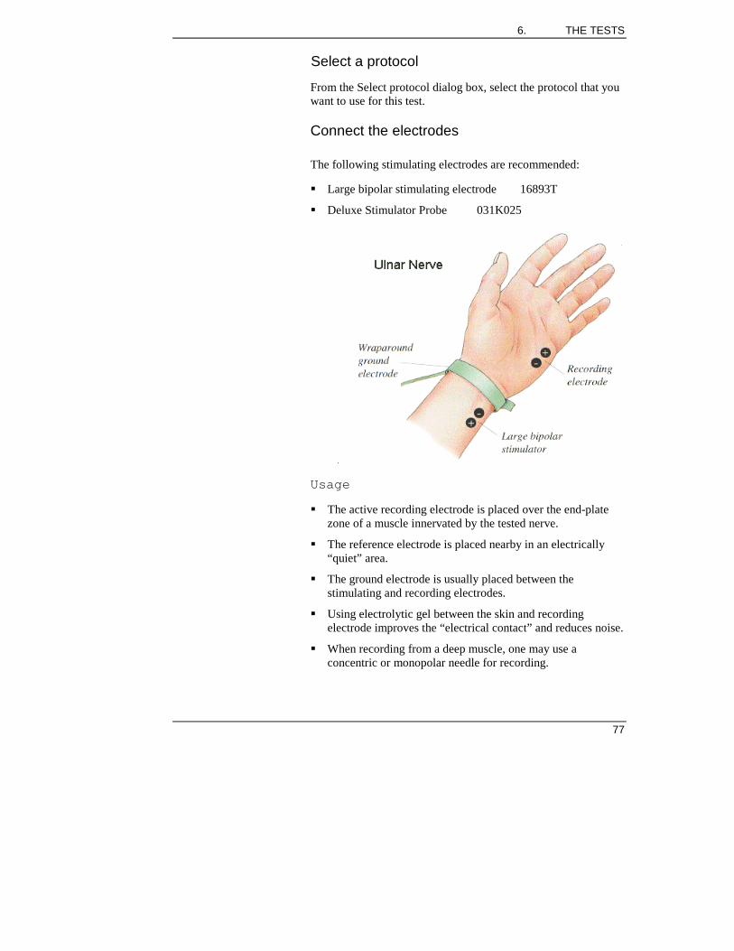
6. THE TESTS
77
Select a protocol
From the Select protocol dialog box, select the protocol that youwant to use for this test.
Connect the electrodes
The following stimulating electrodes are recommended:
" Large bipolar stimulating electrode 16893T
" Deluxe Stimulator Probe 031K025
Usage
" The active recording electrode is placed over the end-platezone of a muscle innervated by the tested nerve.
" The reference electrode is placed nearby in an electrically“quiet” area.
" The ground electrode is usually placed between thestimulating and recording electrodes.
" Using electrolytic gel between the skin and recordingelectrode improves the “electrical contact” and reduces noise.
" When recording from a deep muscle, one may use aconcentric or monopolar needle for recording.

SYNERGY USER MANUAL
78
Note:
The recording electrode is placed on a muscle, even though weare interested in the conduction along the nerve.
The nerve is stimulated using surface electrodes at two or moresites where the nerve is located superficially. The stimulator isoriented so that the cathode of the stimulator faces the activerecording electrode.
Acquire the data
Turn on the amplifier and observe the monitor trace at the lowerright of the screen to ensure that it is noise free. If it is not, checkelectrode connections and cables.
1. Position the stimulator at the appropriate site, and beginstimulation (for recurrent stimulation press the Acquire Onbutton; for a single stimulus press the Acquire Single button).Stimulator settings are indicated on the toolbar.
2. Increase the stimulus intensity and duration as necessary torecord the compound muscle action potential (CMAP).During acquisition, the response is marked automatically (1:Onset, 2: negative peak, 3: baseline crossing, 4: positivepeak, 5: End).
3. When an acceptable response is observed using recurrentstimulation, switch off the stimulus by pressing the AcquireOn button.
4. Assess the validity of the automatic markings, changing thesensitivity if necessary. If one or more marked positions isnot correct:
" Select the marker to change by pressing the Fn button -the selected marker is displayed red and double height(note that marker 1 is automatically selected afteracquisition).
" Rotate the Fn button to move the position of the selectedmarker. When you are happy with its position, press theFn button to move to the next marker.
" If Synergy has not placed automatic markers, but you arehappy with the trace, you can place the markers yourself.Press the Fn button to place marker 1 at its defaultposition, rotate the Fn button to move the marker to thecorrect position, then press the Fn button again to positionthe marker. Continue placing the other markers in thesame way.

6. THE TESTS
79
" If you accidentally move beyond the marker you want tomove or place, you must use the mouse pointer to selectit. You can then position it using the Fn button.
5. To record from another site, press the Next button on thePIU. A blank trace is displayed on the screen: repeat theprocedure as for the first site.
Calculate the velocity
" Distances may be entered after each site has been acquired,or all distances may be entered after all sites have beenacquired.
" Enter distances in cm to 1 decimal place (e.g. 23.5 cm)
" The distance entered will be displayed in the active distancefield.
" Press Enter to accept the distance and to calculate theconduction velocity.
Note 1
" If you enter distances after each site the active distance fieldwill refer to the active store unless you change it by clickingthe mouse or using the tab, Enter or up and down arrow keys.
" If you enter distances after you have acquired all sites theactive distance field will remain at the second site, allowingyou to enter all distances in sequence.

SYNERGY USER MANUAL
80
Note 2
" It is possible to enter Default Distances using the protocoltable:
" Conduction Velocities will then be automatically calculated.
Trace analysis and display
Traces may be selected for marking or trace analysis. Synergyoffers comprehensive and powerful ways of configuring the tracearea. See the following sections later in this chapter:
⇒ Selecting traces
⇒ Moving traces
⇒ Superimposing traces
⇒ Automatic marker placement
⇒ Manual marking of traces
⇒ Changing trace sensitivity
⇒ Changing trace duration
⇒ Compare results
⇒ Trace arithmetic
and also
⇒ Trace area set-up, in chapter 5

6. THE TESTS
81
You can use the full screen to examine and process your trace ifyou wish. Select Full Trace Area ON from the Display menu.
Sorting results
If responses have not been acquired in order (distal to proximal),select Sort from the Analysis Menu to automatically sortresponses in order of ascending latency. Note:
" This facility will only be available if you have just onechannel active.
" All responses acquired for the current nerve study will berearranged, with the distal response placed first and the mostproximal response last.
" If segment distances have been entered and are no longervalid, they will be erased and you will need to re-enter them.
" Reference Values may be deleted following a sort.
Results for Motor NCS tests
Results can be seen on screen immediately, as you acquire data.If columns on the table are not on view you can either scroll thetable or click on results screen from the Display menu to see theTable and Graphs full screen.
Available results ~ Motor NCS
You can display any 15 of the following results:Peak Latency Total AreaTake off Latency DistanceDelta Peak Latency TemperatureDelta take off Latency Recording Site LabelPeak Amplitude Stimulus IntensityPeak to Peak Amplitude Stimulus DurationPeak Duration Take off VelocityTotal Duration Peak Velocity-ve peak Area Path Velocity+ve peak Area
Click on Result Options from the Results menu to select theresults that you want.
Units Used

SYNERGY USER MANUAL
82
The units used to display absolute results are fixed as follows:Result UnitsAll Latency results msAll Amplitude results mVDuration msAll Area types mV msVelocity m/sDistance cmTemperature ° C or ° F
Graphs
Up to two graphs can be displayed on the test screen. Up to sixgraphs can be displayed in the full screen RESULTS view.
You can display any six of the following Graphs (bar type or Yvs X plots)
Peak Latency Take off LatencyPeak Amplitude Peak-to-Peak AmplitudePeak Velocity Take off VelocityPeak Latency v Distance Take off Latency v DistancePeak Amplitude v Distance Peak-to-Peak Amplitude v
DistancePeak Velocity v Distance Take off Velocity v Distance
Click on Graph Options from the Results menu to select theresults that you want.
See also the following sections later in this chapter:
⇒ Results Table
⇒ Result Mode
⇒ Reference values
⇒ Configuring the results table
⇒ Temperature probe

6. THE TESTS
83
Sensory NCS Test
Clinical OverviewThe purpose of the Sensory NCS test is:
1. To investigate the conduction in sensory nerves(demyelination)
2. To assess loss of sensory axons
Running the Sensory NCS test
Select the test
From the entry screen, select the test you want from theappropriate folder.
Select a protocol
From the Select protocol dialog box, select the protocol that youwant to use for this test.
Connect the electrodes

SYNERGY USER MANUAL
84
Usage
1. Prepare the area over the nerve to be stimulated by cleaningthe skin with dry gauze.
2. Surface disk or ring electrodes are placed over the skin wherethe tested nerve is superficially located. The followingelectrodes are recommended:
" Large bipolar stimulating electrode 16893T
" Digital ring electrodes 16639T
3. Apply the stimulating electrodes using a conductive electrodegel. The nerve is stimulated at sites where it is superficiallylocated.
4. The cathode of the stimulator is oriented towards the activerecording electrode.
Acquire the data
Turn on the amplifier and observe the monitor trace at the lowerright of the screen to ensure that it is noise free. If it is not, checkelectrode connections and cables.
1. Position the stimulator at the appropriate site, and beginstimulation (for recurrent stimulation press the Acquire Onbutton; for a single stimulus press the Acquire Single button).Stimulator settings are indicated on the toolbar.
2. Increase the stimulus intensity and duration as necessary torecord the sensory nerve action potential (SNAP). Duringacquisition, the response is marked automatically (1: Onset,2: negative peak, 3: positive peak, 4: End).
3. When an acceptable response is observed using recurrentstimulation, switch off the stimulus by pressing the AcquireOn button.
4. Assess the validity of the automatic markings, changing thesensitivity if necessary. If one or more marked positions isnot correct:
" Select the marker to change by pressing the Fn button -the selected marker is displayed red and double height(note that marker 1 is automatically selected afteracquisition).
" Rotate the Fn button to move the position of the selectedmarker. When you are happy with its position, press theFn button to move to the next marker.

6. THE TESTS
85
" If Synergy has not placed automatic markers, but you arehappy with the trace, you can place the markers yourself.Press the Fn button to place marker 1 at its defaultposition, rotate the Fn button to move the marker to thecorrect position, then press the Fn button again to positionthe marker. Continue placing the other markers in thesame way.
" If you accidentally move beyond the marker you want tomove or place, you must use the mouse pointer to selectit. You can then position it using the Fn button.
5. To record from another site, press the Next button on thePIU. A blank trace is displayed on the screen: repeat theprocedure as for the first site.
Calculate the velocity
" Distances may be entered after each site has been acquired,or all distances may be entered after all sites have beenacquired.
" Enter distances in cm to 1 decimal place (e.g. 23.5 cm)
" The distance entered will be displayed in the active distancefield.
" Press Enter to accept the distance and to calculate theconduction velocity.
Note 1
" If you enter distances after each site the active distance fieldwill refer to the active store unless you change it by clickingthe mouse or using the tab, Enter or up and down arrow keys.
" If you enter distances after you have acquired all sites theactive distance field will remain at the second site, allowingyou to enter all distances in sequence.
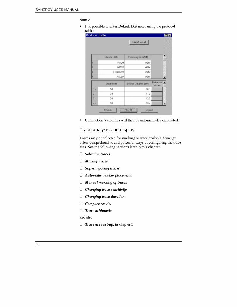
SYNERGY USER MANUAL
86
Note 2
" It is possible to enter Default Distances using the protocoltable:
" Conduction Velocities will then be automatically calculated.
Trace analysis and display
Traces may be selected for marking or trace analysis. Synergyoffers comprehensive and powerful ways of configuring the tracearea. See the following sections later in this chapter:
⇒ Selecting traces
⇒ Moving traces
⇒ Superimposing traces
⇒ Automatic marker placement
⇒ Manual marking of traces
⇒ Changing trace sensitivity
⇒ Changing trace duration
⇒ Compare results
⇒ Trace arithmetic
and also
⇒ Trace area set-up, in chapter 5

6. THE TESTS
87
You can use the full screen to examine and process your trace ifyou wish. Select Full Trace Area ON from the Display menu.
Sorting results
If responses have not been acquired in order (distal to proximal),select Sort from the Analysis Menu to automatically sortresponses in order of ascending latency. Note:
" This facility will only be available if you have just onechannel active.
" All responses acquired for the current nerve study will berearranged, with the distal response placed first and the mostproximal response last.
" If segment distances have been entered and are no longervalid, they will be erased and you will need to re-enter them.
" Reference Values may be deleted following a sort.
Results for the Sensory NCS test
Results can be seen on screen immediately, as you acquire data.If columns on the table are not on view you can either scroll thetable or click on results screen from the Display menu to see theTable and Graphs full screen.
Available results ~ Sensory NCS
You can display any 15 of the following results:Peak Latency Total AreaTake off Latency DistanceDelta Peak Latency TemperatureDelta take off Latency Recording Site LabelPeak Amplitude Stimulus IntensityPeak to Peak Amplitude Stimulus DurationPeak Duration Take off VelocityTotal Duration Peak Velocity-ve peak Area Path Velocity+ve peak Area
Click on Result Options from the Results menu to select theresults that you want.

SYNERGY USER MANUAL
88
Units Used
The units used to display absolute results are fixed as follows:Result UnitsAll Latency results msAll Amplitude results uVDuration msAll Area types uV msVelocity m/sDistance cm
Graphs
Up to two graphs can be displayed on the test screen. Up to sixgraphs can be displayed in the full screen RESULTS view.
You can display any five of the following Graphs:Peak Latency Take off LatencyPeak Amplitude Peak-to-Peak AmplitudePeak Velocity Take off VelocityPeak Latency v Distance Take off Latency v DistancePeak Amplitude v Distance Peak-to-Peak Amplitude v
DistancePeak Velocity v Distance Take off Velocity v Distance
Click on Graph Options from the Results menu to select theresults that you want.
See also the following sections later in this chapter:
⇒ Results Table
⇒ Result Mode
⇒ Reference values
⇒ Configuring the results table

6. THE TESTS
89
F-Wave Test
Clinical OverviewThe purpose of the F-Wave Test is:
1. To investigate the conduction in proximal nerve segmentsthat are not assessed by the nerve conduction study
2. To assess excitability of motor neurons
3. To assess loss of motor axons
Running the F-Wave test
Select the test
From the entry screen, select the test you want from theappropriate folder.
Select a protocol
From the Select protocol dialog box, select the protocol that youwant to use for this test.

SYNERGY USER MANUAL
90
Connect the electrodes
Usage
1. The active recording electrode is placed over the end-platezone of a muscle innervated by the tested nerve.
2. The reference electrode is placed nearby in an electrically“quiet” area.
3. The ground electrode is usually placed between thestimulating and recording electrodes.
4. Using electrolytic gel between the skin and recordingelectrode improves the electrical contact and reduces noise.
5. When recording from a deep muscle, one may use aconcentric or monopolar needle for recording.
Note:
The stimulation sites are the same as in Motor NCS. Usually, theF Wave recordings are by stimulation at the distal site only usingone of the following:
" Large bipolar stimulating electrode 16893T
" Deluxe Stimulator Probe 031K025
One may reverse the polarity of the stimulator pins, i.e. theanode of stimulator is closer to the active recording electrode toprevent anodal block.

6. THE TESTS
91
Acquire the data
Turn on the amplifier and observe the monitor trace at the lowerright of the screen to ensure it is noise free. If it is not, checkelectrode connections and cables. The monitor trace also allowsyou to assess whether the patient is relaxed.
1. Position the Stimulator at the appropriate site.
2. Begin stimulation (for recurrent stimulation, press theAcquire On button; for a single stimulus press the AcquireSingle button), and adjust the stim intensity, if necessary, toacquire a supramaximal compound muscle action potential(CMAP). If using recurrent stimulation, acquisition stopsautomatically after acquiring 10 traces.
3. Traces are displayed on the screen using splitsensitivity, with the CMAP displayed to the left of the Fmincursor, and the F Wave displayed to the right. If any of thetraces were acquired at submaximal intensity, press the Erasebutton twice to delete all traces. Press the Acquire On orAcquire Single button to acquire new traces.
Measure and record the minimum F latency
Rotate the Fn button to position the cursor at the onset of theearliest F wave. Note the latency value, which is displayed in theVertical Cursors table. Record the minimum F latency in theresult table by pressing the Fn button.
Calculate the velocity
Velocity is calculated using the formula:
Velocity =
Trace analysis and display
Traces may be selected for marking or trace analysis. Synergyoffers comprehensive and powerful ways of configuring the tracearea. See the following sections later in this chapter:
⇒ Selecting traces
⇒ Moving traces
(2 x segment distance)
(Min F-M latency - 1 ms)

SYNERGY USER MANUAL
92
⇒ Superimposing traces
⇒ Automatic marker placement
⇒ Manual marking of traces
⇒ Split sensitivity
⇒ Changing trace sensitivity
⇒ Changing trace duration
and also
⇒ Trace area set-up, in chapter 5
You can use the full screen to examine and process your trace ifyou wish. Select Full Trace Area ON from the Display menu.
Results for F-Wave tests
Results can be seen on screen immediately, as you acquire data.If columns on the table are not on view you can either scroll thetable or click on results screen from the Display menu to see theTable and Graphs full screen.
Available results ~ F-Wave
You can display any of the following results: F Latency F Velocity F-M Latency F Ratio F Amplitude A Latency F / M Amplitude Distance M Latency Temperature M Amplitude Patient Height % F
Click on Result Options from the Results menu to select theresults that you want.
Units Used
The units used to display results are fixed as follows: Result Unit All Latency results ms All Amplitude results mV % F % Temperature ° C or ° F F Velocity m/s F Ratio % Distance cm Patient Height m

6. THE TESTS
93
See also the following sections later in this chapter:
⇒ Results Table
⇒ Reference values
⇒ Configuring the results table
⇒ Temperature probe

SYNERGY USER MANUAL
94
H-Reflex Test
Clinical OverviewThe purpose of the H-Reflex Test is to investigate conduction inthe proximal segments of the tibial nerve.
Running the H-Reflex test
Select the test
From the entry screen, select the test you want from theappropriate folder.
Select a protocol
From the Select protocol dialog box, select the protocol that youwant to use for this test.
Connect the electrodes
1. The active surface recording electrode is placed on theGastrocnemius or Soleus muscle
2. The reference electrode is placed on the back of the leg, justabove the foot
3. The ground electrode is placed between the active recordingelectrode and the stimulating electrode.
4. The following stimulating electrodes are recommended:
" Large bipolar stimulating electrode 16893T
" Deluxe Stimulator Probe 031K025
The tibial nerve is stimulated in popliteal fossa with anodefacing the active recording surface.
Acquire the data
Turn on the amplifier and observe the monitor trace at the lowerright of the screen to ensure it is noise free. If it is not, checkelectrode connections and cables. The monitor trace also allowsyou to assess whether the patient is relaxed.
1. Position the stimulator at the appropriate site.

6. THE TESTS
95
2. Press the Stim key to switch on the stimulus withoutacquiring data.
3. Press the Acquire Single Key to stimulate and Acquire asingle response. Press the Acquire ON Key to performcontinuous Acquisition. The data acquired will automaticallyfill each cascade.
4. Gradually increase the stimulus intensity.
5. To stop acquisition press either Acquire Key again.
Measure and record the minimum H latency
Rotate the Fn button to position the cursor at the onset of thelargest amplitude H response. Note the latency value, which isdisplayed in the Vertical Cursors table. Record the minimum Hlatency in the result table by pressing the Fn button.
Autocompare
If you have already performed this test on the opposite side,press the F9 function key to display results from both sides, sothat you can compare them. When you have finished, press F9again to return to the normal display.
Trace analysis and display
Traces may be selected for marking or trace analysis. Synergyoffers comprehensive and powerful ways of configuring the tracearea. See the following sections later in this chapter:
⇒ Selecting traces
⇒ Moving traces
⇒ Superimposing traces
⇒ Automatic marker placement
⇒ Manual marking of traces
⇒ Split sensitivity
⇒ Changing trace sensitivity
⇒ Changing trace duration
⇒ Compare results
⇒ Trace arithmetic
and also

SYNERGY USER MANUAL
96
⇒ Trace area set-up, in chapter 5
You can use the full screen to examine and process your trace ifyou wish. Select Full Trace Area ON from the Display menu.
Results for H-Reflex tests
Results can be seen on screen immediately, as you acquire data.If columns on the table are not on view you can either scroll thetable or click on results screen from the Display menu to see theTable and Graphs full screen.
Available results ~ H-Reflex
You can display any of the following results: M Latency H-M Latency M Amplitude peak Max M Ampl / Max H
Ampl M Amplitude peak-peak Temperature H Latency F Latency H Amplitude peak Facilitation H Amplitude peak-peak Response Number
Click on Result Options from the Results menu to select theresults that you want.
Units Used
The units used to display results are fixed as follows: Result Unit All Latency results ms All Amplitude results mV Max M Ampl / Max HAmpl
%
Temperature degrees C or F
See also the following sections later in this chapter:
⇒ Results Table
⇒ Reference values
⇒ Configuring the results table
⇒ Temperature probe

6. THE TESTS
97
Needle EMG Test
Clinical OverviewThe purpose of the Needle EMG Test is:
1. To assess the excitability of the muscle Fibres:
" Insertional activity
" Spontaneous activity
2. To assess the morphological changes in the motor unit:
" Motor Unit potential analysis
3. To assess the number of motor units and their recruitmentpattern:
" Inference / Recruitment Pattern Analysis
Running the Needle EMG test
Select the test
From the entry screen, select the test you want from theappropriate folder.
Select a muscle
On entering the test, a muscle selection window is displayed.
1. Select the muscle you are about to record from and press theADD key.
2. Select the side and then press the Acquire button.
Any data you store and any findings you report in the EMGsummary table will be associated with this muscle.Note:
If you do not wish to annotate which muscle you are recordingfrom you can turn off this selection window by selecting Don’tDisplay Muscle List from Test Options in the Display menu.

SYNERGY USER MANUAL
98
If you select more than one muscle, you can report findings formore than one muscle at the same time. This saves time,especially if all the findings are normal. However, if more thanone muscle is selected it is not possible to acquire data.
Connect the electrodes
Usage
The needle is inserted in the tested muscle, preferably away fromthe end-plate zone. For a monopolar needle, the referenceelectrode is placed in an electrically “quiet” area. The groundelectrode is also placed in the vicinity of the tested muscle.
Acquire the data
Turn on the amplifier and observe the monitor trace at the lowerright of the screen to ensure that it is noise free. If it is not, checkelectrode connections and cables.
1. Change the sensitivity and sweep duration as necessary.
2. Press the Fn button on the PIU to turn on the amplitudetrigger. Rotate the Fn button to adjust the amplitude level.
3. Select a display format by pressing the relevant function key:
" Monitor gives a free-running full screen EMG display
" Complex 1 shows the monitor signal on the left of thescreen and the rastered signal on the right. This displayformat is useful for assessing motor unit potentialwaveform, and the firing rate.
" Complex 2 shows the signal at normal speed (10 ms/div)on the left of the screen, and at slow speed (50 ms/div) onthe right. This display format is useful for assessingspontaneous activity and the interference pattern atmaximal effort.
Note:
When using the Complex 1 or Complex 2 display format, signalsmust be acquired before they are displayed on the right half ofthe screen.

6. THE TESTS
99
4. Acquire signals by pressing the Acquire On button on thePIU.
5. Select the next muscle. Ensure that EMG acquisition isturned off, and press the F1 function key to select a newmuscle. Repeat the procedure given above.
Automatic MUAP Analysis
It is possible to Average and automark triggered MUAPs
" The Marking Algorithm is turned ON/OFF in the AcquisitionSetup dialog box (select Setup from the Acquisition menu)
" Turn the Averager ON (again, from the Acquisition menu)
At Acquire OFF the MUAP will be automarked and the MUAPresult table updated.
LongTrace™
LongTrace is a special display format for traces in EMG tests,that allows you to display a long run of data on the screen. Thedata is displayed in a compressed format, but there is no loss ofresolution since the uncompressed version of the trace is alsodisplayed.
Setting up LongTrace
1. Choose Setup from the Acquisition menu.
2. In the dialog box that is displayed, set the LongTraceduration in the box labelled LongTrace. The duration is amultiplication factor of the sweep duration. For example,with a sweep duration of 100 ms and a LongTrace factor of100, 10 seconds of data are displayed on the screen.

SYNERGY USER MANUAL
100
Using LongTrace
With LongTrace set, acquire data as normal. When you stopacquiring data, two traces are displayed with a review barbetween them:
" The top trace is the long (compressed) trace.
" The bottom trace is an uncompressed portion of the longtrace, as defined by the review bar.
" The review bar defines a section of the LongTrace to displayin the bottom trace.
You can move the review bar under any part of the LongTracedisplay, and can vary its length so that the bottom trace displaysthe portion of the trace you are interested in:
" To move the review bar, click in its centre and drag it to thenew position.
" To change the length of the review bar, click on either endand drag.
LivePlay™ mode
LivePlay is included as standard.
LivePlay allows you to replay up to 20 s of EMG data withAudio. Re-played data can be re-analysed - e.g. re-triggered, etc.
If LivePlay is set to ON in the Acquisition Set-up dialog box(under Options), the last 20 seconds of acquired data is held in abuffer allowing it to be replayed with Audio, re-analysed orsaved to disk.
When LivePlay is selected the system goes into LivePlay mode.The system starts playing the signal in the 20 s buffer starting at0 sec. A dialog box is displayed indicating the current position ofthe signal being replayed; you can change this by dragging thebar with a mouse.

6. THE TESTS
101
Four buttons are displayed:Play/Stop Starts and stops replay from the LivePlay bufferLoad Allows you to recall previously saved LivePlay
files. A selection of samples files are availablein C:\My documents\Resources\LivePlayExamples. These can be used for training.Note: Files MUST have been named with theextension .MRL
Save Allows you to save the current contents of theLivePlay buffer under the Patient name in theCatalog. If no patient name has been entered inthe Patient Demographics then this option is notavailable.Note: LivePlay files contain raw data includingaudio and are large. A file containing 20 sec ofdata will be about 2 Mbytes. Files MUST benamed with the extension .MRL.
Save As Allows you to save the current contents of theLivePlay buffer if no patient name has beenentered in the Patient DemographicsNote: LivePlay files contain raw data includingaudio and are large. A file containing 20 sec ofdata will be about 2 Mbytes. Files MUST benamed with the extension .MRL.
Close Takes you out of LivePlay and back to normaldata Acquisition.
Trace analysis and display
Traces may be selected for marking or trace analysis. Synergyoffers comprehensive and powerful ways of configuring the tracearea. See the following sections later in this chapter:
⇒ Selecting traces
⇒ Moving traces
⇒ Superimposing traces
⇒ Automatic marker placement
⇒ Manual marking of traces
⇒ Changing trace sensitivity

SYNERGY USER MANUAL
102
⇒ Changing trace duration
and also
⇒ Trace area set-up, in chapter 5
You can use the full screen to examine and process your trace ifyou wish. Select Full Trace Area ON from the Display menu.
Creating an EMG report
There are two ways of creating an EMG Summary Report, usingthe Summary Toolbar, or using the New Muscle function.
Using the Summary Toolbar
1. Select the Summary Toolbar, if necessary, by pressing theF10 function key. When the toolbar is selected, its top lineappears in blue.
2. Press Enter to display settings for the selected EMGcharacteristic.
3. Use the left and right arrow keys to select the desired EMGcharacteristic (such as Fib or PSW).
4. Use the up and down arrow keys to select the correct settingfor the characteristic.
5. When you have finished entering the characteristics, pressEnter.
Using the New Muscle function
Report on one or more muscles by selecting a muscle and sideand pressing ADD. Then select the Report button.
For each Heading select the appropriate findings and press OK.
Select EMG Summary to display the current Summary Table.
Results for Needle EMG tests
Results can be seen on screen immediately, as you acquire data.If columns on the table are not on view you can either scroll thetable or click on results screen from the Display menu to see theTable and Graphs full screen.
Available results ~ Needle EMG
You can display any of the following results:

6. THE TESTS
103
Phases DurationTurns AreaSweep Count Amplitude
Click on Result Options from the Results menu to select theresults that you want.
Units Used
The units used to display results are fixed as follows:Result UnitPhases, Turns, SweepCount and Firing Rate
No unit
Duration msArea mVmsAmplitude mV
See also the following sections later in this chapter:
⇒ Results Table
⇒ Reference values
⇒ Configuring the results table
⇒ Temperature probe

SYNERGY USER MANUAL
104
Repetitive Nerve Stimulation Test
Clinical OverviewThe purpose of the Repetitive Nerve Stim Test is:
1. To diagnose diseases of the neuromuscular junction (NMJ),i.e. Myasthenia Gravis, Eaton-Lambert Syndrome, Botulinumintoxication, etc.
2. The results of this test may also be abnormal in other diseasesdue to the secondary involvement of the NMJ.
3. Although it can be performed in any muscle that is used fornerve conduction studies, it is often performed in proximalmuscles (e.g. Nasalis, Trapizius, Deltoid, Anconius, etc) thattend to be more sensitive in diagnosing Myasthenia Gravis.
4. In many laboratories, the ADM muscle used for Ulnar nerveconduction study is also tested.
Running the Repetitive Nerve Stim test
Select the test
From the entry screen, select the test you want from theappropriate folder.
Select a protocol
From the Select protocol dialog box, select the protocol that youwant to use for this test.

6. THE TESTS
105
Connect the electrodes
Usage
1. First, the electrodes are placed on the tested muscle,preferably over the end-plate area.
2. The stimulator is placed on the appropriate nerve using oneof the following:
" Large bipolar stimulating electrode 16893T
" Deluxe Stimulator Probe 031K025
Acquire the data
The Repetitive Nerve Stim test has three Acquisition/Stimmodes. The mode is selected via the Acquisition menu.
" Stim Set-up Mode allows you to stimulate and obtain asupramaximal response without acquiring data
" Rep Stim Mode is used to deliver a stimulation train andacquire the data (up to 20 stims)
Stim Set-up Mode
1. When the test is first entered it will be in Stim Set-up Mode.
2. This mode is used to establish supramaximal stimulation.

SYNERGY USER MANUAL
106
3. Press Acquire ON to lock acquisition ON.
4. Adjust the stimulus intensity until a supramaximal responseis obtained. Each cascade will update in turn.
5. Exit Stim Set-up Mode either by pressing Next or selectingRepStim Mode.
Notes:
" No data is kept when Stim Set-up is exited.
" A specific Stim Set-up Rep Rate may be set up.
" The Stim Set-up Rep Rate is set up in the Electrical StimSet-up dialog. Select Stim Options from this dialog tochange these settings.
Rep Stim Mode
Having established the appropriate stimulation level, select theREPSTIM mode of operation. This erases all traces and resultson the screen. The system is now ready to acquire a train of upto 20 responses.
" The Train Length (number of responses acquired) can be setto between 2 and 20 in the Electrical Stim Set-up dialogbox, accessed via the Stimulus menu.
" The Rep. Rate used is set up in the Electrical Stim Set-updialog box, accessed via the Stimulus menu.
" Pressing Acquire begins stimulation and Acquisition. Tracesare automatically marked during acquisition.
" When the Train Length limit has been reached, Acquire isturned off automatically.
" Results are updated based on the sweeps used for DecrementResponse.
" The first sweep is shown in a specific colour (colour1). TheDecrement sweeps used for result calculations are also seenin a different colour. Other sweep colours are standard.
Pressing Next allows you to acquire another train.
It is possible to set an automatic sequence for this test. This issetup in the Rep Stim Table dialog found in Change TrainLabel under the Results menu. Enter the Pause period whichshould follow each run.

6. THE TESTS
107
To set acquisition into an automatic sequence:
" Select Continuous Sequences from the Acquisition menu
" Then press the Acquisition button on the control panel
" The Pause period set is the time before the next acquisitioncommences
" Acquisition will continue until it is turned off
Trace analysis and display
Traces may be selected for marking or trace analysis. Synergyoffers comprehensive and powerful ways of configuring the tracearea. See the following sections later in this chapter:
⇒ Selecting traces
⇒ Moving traces
⇒ Superimposing traces
⇒ Automatic marker placement
⇒ Manual marking of traces
⇒ Changing trace sensitivity
⇒ Changing trace duration
⇒ Compare results

SYNERGY USER MANUAL
108
⇒ Trace arithmetic
and also
⇒ Trace area set-up, in chapter 5
You can use the full screen to examine and process your trace ifyou wish. Select Full Trace Area ON from the Display menu.
Results for Repetitive Nerve Stim tests
Results can be seen on screen immediately, as you acquire data.If columns on the table are not on view you can either scroll thetable or click on results screen from the Display menu to see theTable and Graphs full screen.
Available results ~ Repetitive NerveStim
You can display any of the following results: Amplitude Facilitation Area Area Facilitation Amplitude Delta Amplitude 1 Rate Delta Amplitude 2 Delta Response 1 Delta Area 1 Delta Response 2 Delta Area 1 Temperature
Click on Table Options from the Results menu to select theresults that you want.
Units Used
The units used to display results are fixed as follows: Result Unit All Area results mVms All Amplitude results mV All Delta Amplitude andArea results
%
Temperature degrees C Rate pps
Decrement Response
You can define up to two sweeps that are used to calculate aDecrement value. The responses selected are used forAmplitude and Area ratios with respect to the first response.
See also the following sections later in this chapter:
⇒ Results Table

6. THE TESTS
109
⇒ Result mode
⇒ Reference values
⇒ Configuring the results table
⇒ Temperature probe

SYNERGY USER MANUAL
110
Blink Reflex Test
Clinical OverviewBlink reflex is a special motor nerve conduction procedure toassess the facial nerves function, e.g. in Bell's Palsy. It isperformed on only the left and right supra-orbital nerve whilerecording responses bilaterally. The stimulation can be in theform of electrical pulses or mechanical excitation using a reflexhammer.
The response contains two waves; R1 and R2. The R1 is seenonly on the ipsilateral side (i.e. same side of stimulation). Theipsi and contralateral sides have an R2 response.
Running the Blink Reflex test
Select the test
From the entry screen, select the test you want from theappropriate folder.
Select a protocol
From the Select protocol dialog box, select the protocol that youwant to use for this test.
Connect the electrodes
Signals are recorded from 2 channels
The default set-up is:
Channel 1 Records Left side
Channel 2 Records Right side
The recording electrodes are placed over the appropriate area.
Usually electrical stimulation is used to excite the nerve near thefrontal notch. Recommended electrodes are:
" Large bipolar stimulating electrode 16893T
" Deluxe Stimulator Probe 031K025

6. THE TESTS
111
Acquire the data
Turn on the amplifier and observe the monitor trace at the lowerright of the screen to ensure that it is noise free. If it is not, checkelectrode connections and cables. Ask the patient to wink oneeye at a time, and check that the EMG activity is on the expectedchannel (channel 1 for the left eye, channel 2 for the right eye).
1. Stimulate in the supraorbital notch (for recurrent stimulation,press the Acquire On button; for a single stimulus press theAcquire Single button). Perform four trials, since thewaveform changes on successive stimuli.
2. If traces are not acceptable, press the Erase button on the PIUto clear the trace area.
3. If using recurrent stimulation, press the Acquire On button tostop stimulation. When you stop acquisition, both of the mostrecently acquired traces are selected.
4. Measure the latencies on the first channel set. Press the uparrow key to ensure that only a trace from the first channelset is selected (highlighted in yellow), then if necessary pressthe Fn button to select the R1 cursor (displayed in red).Rotate the Fn button to position the cursor at the onset of R1(if R1 is not expected, position the R1 cursor at the extremeleft of the display): the latencies are displayed in the VerticalCursors table. Press the F7 function key to record thelatencies in the results table.
5. Press the Fn button to select the R2 cursor, position thecursor at the onset of R2, and record the latencies in theresults table as for R1.
6. Press the down arrow key until a trace from the secondchannel set is selected (highlighted in yellow), then positionthe R1 and R2 cursors, and record the latencies, as for thefirst channel set.
7. Set up Synergy to record from the other side by pressing theNext button on the PIU. This clears the trace area. Repeat thestimulation process as described above.
Review
If you want to review the trials from both sides, press the F10function key to select the complex 1 display mode.

SYNERGY USER MANUAL
112
In complex 1 display mode, the display is split in half. To movefrom one half to the other, press the F11 function key. To returnto the default display, press the F9 function key.
Left half
The left half of the display shows four traces:
" The top two represent the last trial for the first side used instimulation.
" The bottom two represent the last trial for the second sideused in stimulation.
The selected side is highlighted by a yellow square to the left ofthe traces. Use the up and down arrow keys to select the otherside for review.
Right half
The right half of the display shows all four trials for the selectedside in the left half of the display.
Trace analysis and display
The default protocol assumes stimulation on the left side first,then on the right side. If you stimulated the right side first, youneed to change the labels manually, as follows:
1. Press the F5 function key to display the Results menu.
2. Press S to select Change Site Label, then click the mousepointer on the labels and change them as necessary.
3. Press Enter to return to the acquisition screen.
See also the following sections later in this chapter:
⇒ Selecting traces
⇒ Moving traces
⇒ Superimposing traces
⇒ Manual marking of traces
⇒ Changing trace sensitivity
⇒ Changing trace duration
⇒ Compare results
⇒ Trace arithmetic
and also
⇒ Trace area set-up, in chapter 5

6. THE TESTS
113
You can use the full screen to examine and process your trace ifyou wish. Select Full Trace Area ON from the Display menu.
Results for Blink Reflex tests
Results can be seen on screen immediately, as you acquire data.If columns on the table are not on view you can either scroll thetable or click on results screen from the Display menu to see theTable and Graphs full screen.
Use the custom results set-up to create the Blink Reflex results.
See also the following sections later in this chapter:
⇒ Results Table
⇒ Result Mode
⇒ Reference values
⇒ Configuring the results table
⇒ Sorting results
⇒ Temperature probe

SYNERGY USER MANUAL
114
Sympathetic Skin Response Test
Running the Sympathetic Skin Response Test
Select the test
From the entry screen, select the test you want from theappropriate folder
Select a protocol
From the Select protocol dialog box, select the protocol that youwant to use for this test.
Connect the electrodes
The following stimulating electrodes are recommended:
" Large bipolar stimulating electrodes 16893T
" Digital ring electrodes 16639T
Acquire the data
Turn on the amplifier and observe the monitor trace at the lowerright of the screen to ensure that it is noise free. If it is not, checkelectrode connections and cables.
1. Set the stimulus intensity and duration so that the subject canfeel the stimulus (this is usually guessed from the intensitylevels used in earlier nerve conduction studies).
2. Wait until the subject is relaxed and there is a stable baseline,then stimulate and acquire the response by pressing theAcquire Single button on the PIU.
3. Position the vertical cursor at the onset of the response byrotating the Fn button.Note the latency, which is displayed in the Vertical Cursorstable. To record the latency press the F7 function key.
4. To record the response from another site, press the Nextbutton on the PIU. A blank trace is displayed, where you canrepeat the above procedure.
Note:
" Subsequent responses may diminish in amplitude (ordisappear altogether) because of habituation.

6. THE TESTS
115
Interference Pattern Analysis Test
Clinical OverviewAt minimal force of contraction, the EMG signal containsdischarges of only a few motor units (Mus). One may recogniseindividual motor unit potentials (MUPs) by visual assessment.When the force of contraction is increased, more MUs arerecruited and they also discharge at higher rates. The EMGsignal becomes complex in which individual MUPs may not berecognised. This signal, called the Interference Pattern or therecruitment pattern, contains information about the number andsize of MUPs at higher force levels.
The IP (Interference Pattern) signal can be quantified using avariety of features. In the “Turns & Amplitude (TA)” technique,a “turn” occurs at a peak of the EMG signal. If a turn occurs on apositive going peak, the preceding and following turns occur ona negative going peak, and vice versa. Finally, to exclude peaksgenerated by noise, the signal amplitude must change by at least100 uV between successive turns. The number of turns/sec (NT)and the mean amplitude change between successive turns (MA)are measured. EMG signals are recorded at different force levelsranging from minimal to maximum at each of the 6-10 testedsites. A plot of MA versus NT is constructed. Superimposed onthe plot is an area, called the “normal cloud” which containsmore than 95% of data points in normal muscles. In neuropathy,the data points are outside and on the upper side of the normalcloud. In myopathy, the data points are below the normal cloud.
In Expert’s Quantitative IP (Equip) analysis, the signals arequantified using three features. The “activity” measures thefullness of the pattern. It has a value between 1 and 1000 msecwhich corresponds to the number of milliseconds from a onesecond IP signal that contained the spiky components of theMUPs. The amplitude is measured from the signal “envelope”.The “number of small segments (NSS)” quantify the shortduration spikes that correspond to the high frequency componentheard on the audio monitor. The data are acquired and analysedas in TA technique from two plots: Envelope versus activity,NSS versus activity. In neuropathy, the activity values arereduced along with increased envelope amplitude and reducedNSS. In myopathy, the activity values at maximum force are

SYNERGY USER MANUAL
116
normal. The envelope amplitude is reduced and the NSS isincreased.
An EMG signal can be expressed as a sum of harmonicallyrelated sinusoids of different amplitudes. This calculation isusually performed using the so-called “Fast Fourier Transform”algorithm. Special window functions may be applied to thesignal before computing the FFT. This reduces the effect ofdigitizing the EMG signals. A plot of the power in each sinusoid,computed as a square of the amplitude, against the frequency iscalled the power spectrum. The median frequency divides thespectrum divided in two halves. The mean frequency iscomputed by summating the product of frequency and power,and dividing the sum by the power. The power is also related tothe root mean square value of the signal amplitude. The powerspectrum quantifies the sound of the EMG. In myopathy, the IPhas a high pitch sound that corresponds to increased mean ormedian frequency. Changes in amplitude are reflected in theRMS value. The FFT analysis is also useful to assess changes inmuscle due to fatigue.
Technique
Insert the needle into the tested muscle. Adjust the electrodeposition to record signals with “crisp” sound. This ensures thatwe are close to the MUs of the tested muscle. Instruct the patientto give minimal contraction and maintain it. Press the Acquirebutton or the foot switch. By default a 500 msec epoch will beacquired analysed. The result table and graphs will be updated.For the basic TA/Equip analysis, the results are available almostinstantaneously. Perform similar analysis at moderate andmaximum force level. Repeat the process at 6-10 different sitesusing 2-4 different needle insertions. If available, superimposethe normal cloud on the data to assess the abnormality.
With practice, this quantitative study can be finished within 3-5minutes.References
Nandedkar et al : Muscle & Nerve, 9:431-439, 9:491-500, 1986.
Stalberg et al : EEG & Clinical Neurophysiology, 56:672-681,1983.
6. THE TESTS
117
Running the Interference Pattern Analysis test
Select the test
Enter the IP test and select the tested muscle and side.
Select a muscle
On entering the test, a muscle selection window is displayed.
1. Select the muscle you are about to record from and press theADD key.
2. Select the side, and then click on the Acquire button.
3. Any data you store and any findings you report in the EMGsummary table will be associated with this muscle.
Notes:
" If you do not wish to annotate which muscle you arerecording from it is possible to turn this selection window offby selecting Don’t Display Muscle List from Test Options inthe Display menu.
" If you select more than one muscle, it is possible to reportfindings for more than one muscle at the same time. Thissaves time, especially if all the findings are normal.However, if more than one muscle is selected, it will not bepossible to acquire data.
Select a “Normal cloud”
If normal clouds for the tested muscle are known, these can beprogrammed into the system. Choose IP Clouds from theSystem Configuration menu.
Press the Normal Cloud function key. From the pop up list,select the desired cloud. The display of cloud can be turnedON/OFF or a different cloud may be selected using the sameinterface.
Acquire the data
1. Adjust the needle position to record sharp and crisp signals.
2. Instruct the subject to exert the desired force of contractionand maintain it.

SYNERGY USER MANUAL
118
3. Press the Acquire key.The system will acquire 5 sweeps, i.e. 500 msec epoch.
4. Acquisition will stop automatically and analysis initiated.
Analyse the data
The analysis time depends upon the measurements and graphsused for display.
" If only the TA/Equip analysis is selected, the results areavailable instantaneously.
" Computation of the FFT takes slightly longer.
" Plotting a 3D plot of spectrum is more time consuming andmay require several seconds.
" The numerical data is shown in the result table.
" It is also shown graphically on the plots:
Editing the data
" If the results are unsatisfactory, delete the current results bypressing the Erase key on the front panel or by pressing theDelete Site function key.
" You may press the Next key to advance to the next site.However, this is not necessary. When acquisition starts, thesystem automatically does this task for you.
" For more data, go back to the Acquire the Data step above.
Reviewing the results
1. Press the Results function key to see the summary table.This will display all measurements configured for the test,some of which may not displayed in acquisition screen. Pressthe same key to return to the acquisition screen.
2. Click on the site label in the result table to review the tracesfrom an earlier acquisition. The current site label is shown inblue.
3. Press the Print key to obtain a hard copy of the results.

6. THE TESTS
119
Exit
" Press the Test Menu function key to exit the test.
" You may also press the New Muscle key to perform IPanalysis in another muscle.
" Upon exiting the analysis in the current muscle, the data areautomatically transferred to the report generator.

SYNERGY USER MANUAL
120
Multi-MUP Analysis Test
Clinical Overview
Rationale
A motor unit potential (MUP) is a sum of the extracellular actionpotentials (APs) of all muscle Fibres belonging to one motor unit(MU). The shape of the MUP depends upon the MU architecture,i.e. number and size of muscle fibres, terminal innervation, etc.In pathology changes of the MU architecture due to diseaseprocesses will be seen as changes in the MUP waveforms. Thisforms the basis for MUP analysis. In quantitative analysis, 20 ormore MUPs are recorded at minimal force of contraction. Foreach MUP its peak-peak amplitude, duration and number ofphases are measured. A MUP is called polyphasic if it has morethan 4 phases. The mean amplitude, mean duration andpercentage of polyphasic MUPs are computed and comparedagainst appropriate reference values. The latter are affected bythe type of needle, force of contraction and patient age amongother factors. In patients with myopathy, the polyphasic MUPsshould be excluded from the calculation of mean duration toincrease the diagnostic yield.
The MUPs can be identified manually by reviewing free runningEMG traces. Use of a triggered delay line and averagerfacilitates MUP extraction. However, this approach is biasedtowards the large amplitude MUPs. Regardless, acquisition andanalysis of 20 MUPs is quite time consuming.
The multi-MUP analysis (MMA) is a computer aided techniqueof extracting and analysing the MUP. It decomposes the signalinto discharges of the constituent MUPs. The emphasis of thetechnique is to extract good quality MUPs that can be used formeasuring amplitude, duration and phases. Hence, the algorithmdoes not bother to resolve each and every MUP discharge whendifferent MUPs superimpose. It is developed to analyserecordings made at minimal force of contraction and not theinterference pattern generated at moderate force levels. Thus theresults of analysis supplement the visual MUP assessment. Thetechnique is developed to run almost “On Line”, i.e. the resultsare available within a few seconds. Finally, it can identify up to 6different MUPs from a single EMG recording. The system worksbest when the signal contains discharge of 3-4 MUPs. Thesignals are acquired in a free running mode just as in the routineneedle EMG examination. It does not require manipulation of

6. THE TESTS
121
other devices such as the trigger and averager, etc. By analysingmultiple MUPs one is less likely to record from the same motorunit twice. The time required to acquire and analyze 20 differentMUPs is also reduced to just a few minutes.
The MMA algorithm is ideally suited to perform quantitativeanalysis in a fast and efficient manner. In the routine EMGexamination, it can be used to quickly capture examples ofabnormal MUPs, i.e. the “outliers”. A printout from this test willsupplement the subjective assessment and make it moreobjective.
Technique
EMG signals are recorded at minimal force of contraction usinga monopolar or a concentric needle electrode. By default, a tensecond epoch containing discharges of 3-4 motor units (MU) isanalysed. The MU activity is identified based on a rapid changeof voltage, i.e. short rise time and/or high amplitude. Thedischarges of individual MUs are identified and used to extractthe motor unit potential (MUP). Each MUP is quantified bymeasuring features such as amplitude, duration, phases, turns,area/amplitude ratio and firing rate. The stability of the MUPscan also be indicated as YES or NO. The duration, phase andturns measurements can be changed manually. The area andarea/amplitude ratio are automatically recomputed when theduration markers are changed. The mean values of the MUPfeatures and the percentage of polyphasic MUPs are tabulated.The mean values are also computed for the simple MUPs only.The summary results can be presented in a tabulated fashion orby plotting the MUP waveforms.
The signals can be re-viewed post-acquisition. After practice, 20-30 MUPs can be acquired within 5-10 minutes.
References
Nandedkar et al : Muscle & Nerve, 18:1155-1166 1995
Barkhaus et al : Muscle Nerve 1990; 13:247-253
Bischoff et al : Muscle Nerve 1994; 17:842-851
Buchthal and Kamieniecka : Muscle Nerve 1982;5:265-290
McGill and Dorfman : Computer-Aided Electromyography andExpert Systems, New York, Elsevier, 1989, pp 91-101
Nandedkar and Sanders : Med Biol Comput 1989;27:556-571
Stalberg et al : J Clin Neurophysiol 1986;3;313-348

SYNERGY USER MANUAL
122
Stalberg et al : Muscle Nerve 1994;17:392-399
Stewart et al : Muscle Nerve 1989;12:141-148
Running the Multi-MUP Analysis Test
Select the test
From the Test Manager on the right of the entry screen, selectthe test you want from the appropriate folder.
Select a muscle
On entering the test, a muscle selection window is displayed.
1. Select the muscle you are about to record from and press theADD key.
2. Select the side, and then click on the Acquire button.
3. Any data you store and any findings you report in the EMGsummary table will be associated with this muscle.
Notes:
" If you do not wish to annotate which muscle you arerecording from it is possible to turn this selection window offby selecting Don’t Display Muscle List from Test Options inthe Display menu.
" If you select more than one muscle, it is possible to reportfindings for more than one muscle at the same time. Thissaves time, especially if all the findings are normal.However, if more than one muscle is selected, it will not bepossible to acquire data.
" You can select a muscle by double clicking on its name in themuscle selection window.
Acquire the data
Manipulate the needle position to record “crisp” EMG signals.The force of contraction should be minimal. Ideally, the EMGshould contain discharges of 3-4 MUPs.
Begin acquisition. You may change the display mode toComplex 1 to view cascades or Complex 2 to view the longtrace.

6. THE TESTS
123
Cascade display
Long trace display
When the 10 second epoch is acquired, the acquisition will stopautomatically and initiate the analysis.
" You can stop acquisition manually and begin analysis bypressing the Analysis function key.
" To suspend and resume signal acquisition, press the AcquireON key.
" To delete all traces acquired during the current recording,press the Erase key. To return to a state where you canacquire a new set of data, press the Next key (or the middlefootswitch).
" To analyse the data later (for example, after the patient hasleft), press the Next key (or the middle footswitch) to savethe traces to the hard disk. You can then acquire another setof traces.

SYNERGY USER MANUAL
124
Analyse the data
Analysis of a 10 second epoch requires a few seconds. Up to 6MUPs may be extracted.
For each MUP, the system displays the averaged signalsuperimposed on the individual MUP discharges. This makes iteasy to assess the validity of the automated decomposition.
Above the MUP the amplitude, duration, phases and turns arelisted. The beginning and end of the MUP are indicated by themarkers. The discharge pattern is shown in the bottom rightcorner. The horizontal bar represents the duration of epoch. Eachvertical tick mark represents one discharge of the MUP. Theresult table shows the measurements from individual MUPs andalso the summary statistics. You may review these results asdescribed in the Review of current analysis section or press theNext button/function key for the next acquisition.
All results can be reviewed and corrected post-acquisition.
Review of current analysis
1. Use the sensitivity and sweep duration controls to changethese settings. Change the marker positions if necessary. Thephases, turns and stability settings can be changed byclicking in to these fields in the result table.
2. The Edit Screen: To edit and review, click on the MUP. Pressthe Edit MUP function key. The averaged MUP and theindividual discharges are shown. Review the dischargesusing the scroll bar and/or Page up/down keys. Use theSuperimpose function key to assess the validity of thedecomposition and to view the stability of the MUP. Use thefunction keys to delete or accept a MUP for analysis. Adeleted MUP is indicated in grey colour. Press the Edit MUPkey to exit this mode.
3. To combine two MUPs that represent discharges of the sameMU, press the Combine function key. In the dialog box,select the MUPs to be combined. These will be shown in thesuperimposed mode. Click the OK button to proceed withthis task. Press the Cancel button to abort this function.
4. Press the Review EMG function key to see the raw EMGtraces. One can assess the validity of automateddecomposition by identifying the MUPs in the EMG signals.This is usually not necessary, but can be a powerful teachingtool. Press the Analysis key to return to the analysis mode.
5. Press the Reject Site function key to delete or re-accept allMUPs acquired at that site.

6. THE TESTS
125
Review of all results
1. Press the Results function key to view the full result table.This will allow one to assess other MUP parameters that maynot seen in the acquisition screen.
2. Press the All MUPs function key to view MUP traces. Up to25 MUPs can be shown on the display area. If more MUPswere analysed they can be viewed using the scroll bar. Acalibration bar is provided to assess the amplitude andduration of the MUPs. Use the sensitivity and sweep durationknobs to change the MUP display, if necessary. In this mode,one can also change the duration markers of the MUP. Toreview a specific MUP, select it by clicking with the mouse.Press the Edit MUP function key. The details of the revieware described under Review of current analysis above.
3. To review results from an earlier acquired site, click on thesite label in the result table. The label for the current site isindicated in blue.
4. Press the Print function key at any time to obtain a hard copyof the results.

SYNERGY USER MANUAL
126
Single Fibre Jitter Test
Clinical OverviewThe purpose of the Single Fibre EMG Jitter (SFJ) test is to assessthe efficacy of neuromuscular transmission.
Running the SFJ Test (Volitional)
Select the test
From the Test Manager on the right of the entry screen, selectthe test you want from the appropriate folder.
Select a muscle
On entering the test, a muscle selection window is displayed.
1. Select the muscle you are about to record from and press theADD key.
2. Select the side and then press the Acquire button.
Any data you store and any findings you report in the EMGsummary table will be associated with this muscle.Notes:
" If you do not wish to annotate which muscle you arerecording from you can turn off this selection window byselecting Don’t Display Muscle List from Test Options in theDisplay menu.
" If you select more than one muscle, you can report findingsfor more than one muscle at the same time. This saves time,especially if all the findings are normal. However, if morethan one muscle is selected it is not possible to acquire data.
" You can select a muscle by double clicking on its name in themuscle selection window.
Connect the electrodes
" Use an SFEMG needle as the active recording electrode. Theactive recording surface is located in a side port on theopposite side to the bevel.

6. THE TESTS
127
" The cannula acts as a reference electrode, and isautomatically connected to the pre-amplifier by the cable.
" Place the ground electrode close to the tested muscle.
Inserting the needle
The SFEMG electrode has a very small uptake area, so locating apair of action potentials (APs) from the same motor unit (MU)can be difficult. Furthermore, a slight movement of the needlecan significantly reduce the AP amplitude. This makes it difficultto maintain a stable trigger. The following technique helps toreduce problems.
1. Insert the needle at an angle of between 20° and 30° to thesurface of the skin, instead of nearly perpendicular (asperformed in concentric or monopolar needle EMG studies).When the needle moves, the angular insertion produces farless displacement in a radial direction, giving more stable APamplitudes.
2. Insert the needle all the way to the hub and then retract itpartially. The muscle tends to grab the needle and holds itbetter in one place during retraction.
Rotate the needle to investigate fibres in all directions.
Orienting the active electrode
The SFEMG needle has a special holder and cable; a dent on thehub of the holder is on the same side as the recording surface.This makes it easier to orient the needle or to rotate it whileoptimising the signal recordings.
Acquire data
Ask the patient to perform a minimal contraction of the testedmuscle. Adjust the needle position and the trigger level so thatonly one muscle unit (MU) triggers the sweeps. The recordingshould contain at least two time-locked APs that are separatedby, ideally, 400 - 4000 µS.
When the signals are suitable for analysis, press the Acquire ONkey (or footswitch) to stimulate and acquire responses.
" To suspend and resume signal acquisition, press the AcquireON key.
" To delete all traces acquired during the current recording,press the Erase key. To return to a state where you can

SYNERGY USER MANUAL
128
acquire a new set of data, press the Next key (or the middlefootswitch).
" To analyse the data later (for example, after the patient hasleft), press the Next key (or the middle footswitch) to savethe traces to the hard disk. You can then acquire another setof traces.
Analyse the data
When the system reaches the Cascade sweep limit, itautomatically stops acquisition and automatically analyses thedata. If you stop acquisition manually before the sweep limit isreached, press the Analyse key to make Synergy analyse thedata.
The top portion of the trace area shows all acquired sweepssuperimposed on each other. Two windows, called SFJWindow1 and SFJ Window2, are displayed as horizontal barsover the sweeps in this area. When the EMG signal crosses awindow, an AP is detected, and is used for computing the inter-potential interval (IPI):
" The occurrence of AP can be detected from its rising edge orthe falling edge. By default, the rising edge is used, to changeto the falling edge, from the menu bar select Analysis thenSFJ Window Setup.
" If a signal crosses a window at more than one point, its firstcrossing is used to compute the IPI.
" Traces are colour-coded to represent the followingconditions:
Colour ConditionWhite Sweeps used for calculations of jitterRed Sweeps with blocksBlue Sweeps with IPI outside the limits defined
by cursors
By default, SFJ Window1 is centred at the trigger point of thetrace and has a duration of 500 µs. SFJ Window2 begins 500 µslater, and has a duration of 4 ms. It is set at 50% amplitude levelof the trigger point. These settings may need adjustment,depending on the configuration of the signal.
Moving and resizing SFJ Window1 and SFJWindow2
You can move either window using either the mouse or thearrow keys on the keyboard:

6. THE TESTS
129
" To move a window using the mouse, click in the horizontalpart of the bar and drag the window to its new position.
" To move the active window using the keyboard, use the Up,Down, Left and Right arrow keys to move the window to itsnew position.
You can resize either window using the mouse:
" To resize a window, click on one of the vertical ends, anddrag to resize.
Multiple pairs from the same recording
When recording the data for a volitional SFJ test, it is possible torecord three or more time-locked APs. In this case, you cananalyse the additional combinations of APs:
1. Press the New Pair (F2) key.
2. Adjust the positions of SFJ Window1 and SFJ Window2 sothey are over the new pair of APs. The system recalculatesthe results using the new window positions, and displaysthem as a new line in the results table.
Up to 8 separate pairs can be analysed from a single recording.
Sorting traces by firing rate
To display the traces sorted by firing rate, right click on thescreen, and from the popup choose Sort traces. The traces aredisplayed in increasing order of firing rate, and the sequential IPIplot is replaced by a plot of IPI versus IDI.
Results
The system automatically computes the mean inter-potentialinterval (MIPI), mean consecutive difference (MCD), meansorted difference (MSD) and the number of blocked potentials,and displays the values in the results table. The jitter is set equalto the lower of the MCD or MSD values.
Viewing results
The sweeps used in computing the results are shownsuperimposed in the lower half of the trace display window. TheIPI data and traces are colour-coded to represent the followingconditions:

SYNERGY USER MANUAL
130
Colour ConditionWhite Sweeps used for calculations of jitterRed Sweeps with blocksBlue Sweeps with IPI outside the limits
defined by cursors
The sequential IPI plot is shown under the result table, with thevertical scale of this plot set so that the MIPI value isapproximately at the centre. A yellow band is displayed on thisplot, which represents ±3 standard deviations from the MIPI. IPIvalues within these limits are used to compute jitter.
The sequential plot of IPIs is extremely useful to detect tracesthat were acquired due to technical problems in recording (e.g.triggering from two MUs). It is much easier to exclude them byadjusting the IPI limits rather than by excluding themindividually during trace review. The ±3 standard deviation limitwill automatically exclude some of the potentials. To excludeothers, use the mouse to reduce the height of the yellow band.
To manually include or exclude sweeps from analysis:
1. Press the Review key. This displays the first 5 sweeps in thelower half of the trace area.
2. To change the status of an individual sweep (from includedto excluded, or vice versa) click on it with the mouse.
3. To include or exclude all of the displayed traces, right clickon the trace area; from the popup that is displayed, chooseInclude displayed or Exclude displayed.
4. To include or exclude all traces, right click on the trace area;from the popup that is displayed, choose Include all orExclude all.
To accept the calculations and move on to the next recording,press the Next key (or the middle footswitch).
If you move a window, or change between rising and fallingedge, the system automatically recalculates these values.
Blockings generated by mis-triggers are automatically discarded.Results are shown numerically in the result table at the righthand side of the display.
Overriding automatic results
By default, the jitter value is set to the lower of the MCD orMSD values. To use the other value, press the F5 key.
If the algorithm finds blocking, the number of blocks isindicated.. If you believe these are technical artefacts, you can

6. THE TESTS
131
exclude them by pressing the Block (F4) key. The number ofblocks is replaced by the symbol —, and the number ofdischarges analysed changes. To restore the number of blocks,press the Block (F4) key again.
To reject the current pair, press the Delete (F9) key. The entriesin the result table are indicated by —. Press the F9 key again tore-accept the results.
To delete all pairs acquired during the current recording, pressthe Erase key.
Running the SFJ Test (Stimulated)
Select the test
From the Test Manager on the right of the entry screen, selectthe test you want from the appropriate folder.
Select a muscle
On entering the test, a muscle selection window is displayed.
1. Select the muscle you are about to record from and press theADD key.
2. Select the side and then press the Acquire button.
Any data you store and any findings you report in the EMGsummary table will be associated with this muscle.Notes:
" If you do not wish to annotate which muscle you arerecording from you can turn off this selection window byselecting Don’t Display Muscle List from Test Options in theDisplay menu.
" If you select more than one muscle, you can report findingsfor more than one muscle at the same time. This saves time,especially if all the findings are normal. However, if morethan one muscle is selected it is not possible to acquire data.
" You can select a muscle by double clicking on its name in themuscle selection window.

SYNERGY USER MANUAL
132
Connect the electrodes and stimulator
Connecting the stimulator
" Use an SFEMG needle as the active recording electrode. Theactive recording surface is located in a side port on theopposite side to the bevel.
" The cannula acts as a reference electrode, and isautomatically connected to the pre-amplifier by the cable.
" Place the ground electrode close to the tested muscle.
Inserting the needle
The SFEMG electrode has a very small uptake area, so locating apair of action potentials (APs) from the same motor unit (MU)can be difficult. Furthermore, a slight movement of the needlecan significantly reduce the AP amplitude. This makes it difficultto maintain a stable trigger. The following technique helps toreduce problems.
1. Insert the needle at an angle of between 20° and 30° to thesurface of the skin, instead of nearly perpendicular (asperformed in concentric or monopolar needle EMG studies).When the needle moves, the angular insertion produces farless displacement in a radial direction, giving more stable APamplitudes.
2. Insert the needle all the way to the hub and then retract itpartially. The muscle tends to grab the needle and holds itbetter in one place during retraction.
Rotate the needle to investigate fibres in all directions.
Orienting the active electrode
The SFEMG needle has a special holder and cable; a dent on thehub of the holder is on the same side as the recording surface.This makes it easier to orient the needle or to rotate it whileoptimising the signal recordings.
Connecting the stimulator
" Use an intramuscular monopolar needle as the cathode
" Place a surface electrode nearby to use as the anode
Since the stimulation is “near nerve”, set the stimulus intensity tothe low range. This is set via the Stim Setup dialog (from theStimulus menu, choose Stim Setup).

6. THE TESTS
133
Press the STIM key on the front panel to begin stimulation.Adjust the stimulus intensity and the intramuscular cathodeposition so that a faint twitch of the tested muscle can be seen.You may wish to fix the stimulator with tape.
Acquire data
Press the STIM button to begin stimulation. If necessary, adjustthe following until you see APs from a single or more musclefibres:
" The position of the stimulator cathode
" Stimulus intensity
" SFEMG needle position
When the signals are suitable for analysis, press the Acquire ONkey (or the footswitch) to begin acquisition.
" To suspend and resume signal acquisition, press the AcquireON key.
" To delete all traces acquired during the current recording,press the Erase key. To return to a state where you canacquire a new set of data, press the Next key (or the middlefootswitch).
" To analyse the data later (for example, after the patient hasleft), press the Next key (or the middle footswitch) to savethe traces to the hard disk. You can then acquire another setof traces.
Note:
At the threshold of a muscle’s stimulation, there may appear tobe high jitter, even in normal muscle fibres. Therefore, if you seejitter, you should increase the stimulus intensity to ensure thatthe abnormalities of jitter are not artefact caused by inadequatestimulation.
Analyse data
When the system reaches the Cascade sweep limit, itautomatically stops acquisition and automatically analyses thedata. If you stop acquisition manually before the sweep limit isreached, press the Analyse key to make Synergy analyse thedata.
The top portion of the trace area shows all acquired sweepssuperimposed on each other. A window, called SFJ Window2, isdisplayed as a horizontal bar over the sweeps in this area. When

SYNERGY USER MANUAL
134
the EMG signal crosses the window, an AP is detected, and isused for computing the inter-potential interval (IPI):
" The IPI is measured with respect to the onset of the sweep.
" The occurrence of AP can be detected from its rising edge orthe falling edge. By default, the rising edge is used, to changeto the falling edge, from the menu bar select Analysis thenSFJ Window Setup.
" If a signal crosses the window at more than one point, its firstcrossing is used to compute the IPI.
" Traces are colour-coded to represent the followingconditions:
Colour ConditionWhite Sweeps used for calculations of jitterRed Sweeps with blocksBlue Sweeps with IPI outside the limits defined
by cursors
Moving and resizing SFJ Window2
You can move the window using either the mouse or the arrowkeys on the keyboard:
" Using the mouse, click in the horizontal part of the bar anddrag the window to its new position.
" On the keyboard, use the Up, Down, Left and Right arrowkeys to move the window to its new position.
You can resize the window using the mouse:
" Click on one of the vertical ends, and drag to resize.
Multiple pairs from the same recording
When recording the data for a stimulated SFJ test, it is possibleto record two or more time-locked APs. In this case, you cananalyse the additional combinations of APs:
1. Press the New Pair (F2) key.
2. Adjust the position of SFJ Window2 so that it is over the newAPs. The system recalculates the results using the newwindow positions, and displays them as a new line in theresults table.
Up to 8 computations can be performed from a single recording.

6. THE TESTS
135
Sorting traces by firing rate
To display the traces sorted by firing rate, right click on thescreen, and from the popup choose Sort traces. The traces aredisplayed in increasing order of firing rate, and the sequential IPIplot is replaced by a plot of IPI versus IDI.
Results
The system automatically computes the mean inter-potentialinterval (MIPI), mean consecutive difference (MCD), meansorted difference (MSD) and the number of blocked potentials,and displays the values in the results table. The jitter is set equalto the lower of the MCD or MSD values.
Viewing results
The sweeps used in computing the results are shownsuperimposed in the lower half of the trace display window. TheIPI data and traces are colour-coded to represent the followingconditions:
Colour ConditionWhite Sweeps used for calculations of jitterRed Sweeps with blocksBlue Sweeps with IPI outside the limits defined
by cursors
The sequential IPI plot is shown under the result table, with thevertical scale of this plot set so that the MIPI value isapproximately at the centre. A yellow band is displayed on thisplot, which represents ±3 standard deviations from the MIPI. IPIvalues within these limits are used to compute jitter.
The sequential plot of IPIs is extremely useful to detect tracesthat were acquired due to technical problems in recording (e.g.triggering from two MUs). It is much easier to exclude them byadjusting the IPI limits rather than by excluding themindividually during trace review. The ±3 standard deviation limitwill automatically exclude some of the potentials. To excludeothers, use the mouse to reduce the height of the yellow band.
To manually include or exclude sweeps from analysis:
1. Press the Review key. This displays the first 5 sweeps in thelower half of the trace area.

SYNERGY USER MANUAL
136
2. To change the status of an individual sweep (from includedto excluded, or vice versa) click on it with the mouse.
3. To include or exclude all of the displayed traces, right clickon the trace area; from the popup that is displayed, chooseInclude displayed or Exclude displayed.
4. To include or exclude all traces, right click on the trace area;from the popup that is displayed, choose Include all orExclude all.
To accept the calculations and move on to the next recording,press the Next key (or the middle footswitch).
If you move a window, or change between rising and fallingedge, the system automatically recalculates these values.
Blockings generated by mis-triggers are automatically discarded.Results are shown numerically in the result table at the righthand side of the display.
Overriding automatic results
By default, the jitter value is set to the lower of the MCD orMSD values. To use the other value, press the F5 key.
If the algorithm finds blocking, the number of blocks isindicated.. If you believe these are technical artefacts, you canexclude them by pressing the Block (F4) key. The number ofblocks is replaced by the symbol —, and the number ofdischarges analysed changes. To restore the number of blocks,press the Block (F4) key again.
To reject the current pair, press the Delete (F9) key. The entriesin the result table are indicated by —. Press the F9 key again tore-accept the results.
To delete all pairs acquired during the current recording, pressthe Erase key.

6. THE TESTS
137
Fibre Density Analysis Test
Clinical OverviewThe purpose of this test is to assess the grouping of muscle fibresbelonging to the same motor unit (MU).
Running the Fibre Density Analysis Test
Select the test
From the Test Manager on the right of the entry screen, selectthe test you want from the appropriate folder.
Select a muscle
On entering the test, a muscle selection window is displayed.
1. Select the muscle you are about to record from and press theADD key.
2. Select the side and then press the Acquire button.
Any data you store and any findings you report in the EMGsummary table will be associated with this muscle.Note:
" If you do not wish to annotate which muscle you arerecording from you can turn off this selection window byselecting Don’t Display Muscle List from Test Options in theDisplay menu.
" If you select more than one muscle, you can report findingsfor more than one muscle at the same time. This saves time,especially if all the findings are normal. However, if morethan one muscle is selected it is not possible to acquire data.
" You can select a muscle by double clicking on its name in themuscle selection window.
Connect the electrodes
" Use an SFEMG needle as the active recording electrode. Theactive recording surface is located in a side port on theopposite side to the bevel.

SYNERGY USER MANUAL
138
" The cannula acts as a reference electrode, and isautomatically connected to the pre-amplifier by the cable.
" Place the ground electrode close to the tested muscle.
Inserting the needle
The SFEMG electrode has a very small uptake area, so locating apair of action potentials (APs) from the same motor unit (MU)can be difficult. Furthermore, a slight movement of the needlecan significantly reduce the AP amplitude. This makes it difficultto maintain a stable trigger. The following technique helps toreduce problems.
1. Insert the needle at an angle of between 20° and 30° to thesurface of the skin, instead of nearly perpendicular (asperformed in concentric or monopolar needle EMG studies).When the needle moves, the angular insertion produces farless displacement in a radial direction, giving more stable APamplitudes.
2. Insert the needle all the way to the hub and then retract itpartially. The muscle tends to grab the needle and holds itbetter in one place during retraction.
Rotate the needle to investigate fibres in all directions.
Orienting the active electrode
The SFEMG needle has a special holder and cable; a dent on thehub of the holder is on the same side as the recording surface.This makes it easier to orient the needle or to rotate it whileoptimising the signal recordings.
View sweeps
Ask the patient to perform a minimal contraction of the testedmuscle.
Adjust the needle position and the trigger level so that only oneMU triggers the sweeps. Maximise the amplitude of thetriggering AP by rotating or moving the needle.
If you want to store the sweeps, press the Acquire ON key.

6. THE TESTS
139
Enter data
Observe and count APs and enter them into the table.
1. Type the number of APs into the yellow highlighted box andpress the Enter key.
2. A list of options for signal stability is displayed, with Normalselected as the default. Use the Up and Down arrow keys tohighlight the correct signal stability, and press the Enter key.Note that the last option (a blank line) allows you to enteryour own text to describe the signal stability.
3. Press the Next key (or the middle footswitch) to advance tothe next site. The yellow highlight moves to the next line inthe table. A maximum of 20 sites is allowed in the table.
Based on the values you enter, Synergy calculates the meanvalue and standard deviation, and displays them at the bottom ofthe table.Notes:
" You can change data for any site in the table, by clicking onthe appropriate row.
" Count APs with peak-to-peak amplitude greater than 200 µVand rise time less than 300 µs. If the APs superimpose oneach other, you can modify the criteria, to an amplitudegreater than 100 µV, or a formation of a notch in therising/falling edge of the first AP.

SYNERGY USER MANUAL
140
Macro EMG Test
Clinical OverviewThe main purpose of this test is to assess the size of motor units(MUs).
In addition, it can also be used to measure fibre density, and tomake subjective assessment of jitter.
Running the Macro EMG Test
Select the test
From the Test Manager on the right of the entry screen, selectthe test you want from the appropriate folder.
Select a muscle
On entering the test, a muscle selection window is displayed.
1. Select the muscle you are about to record from and press theADD key.
2. Select the side and then press the Acquire button.
Any data you store and any findings you report in the EMGsummary table will be associated with this muscle.Notes:
" If you do not wish to annotate which muscle you arerecording from you can turn off this selection window byselecting Don’t Display Muscle List from Test Options in theDisplay menu.
" If you select more than one muscle, you can report findingsfor more than one muscle at the same time. This saves time,especially if all the findings are normal. However, if morethan one muscle is selected it is not possible to acquire data.
" You can select a muscle by double clicking on its name in themuscle selection window.

6. THE TESTS
141
Connect the electrodes
The electrode used in the Macro EMG test is a modified SFEMGneedle, insulated except for the distal 15mm. Using this needle,it is possible to record a single fibre channel and a macro channelsimultaneously.
" The active recording surface for the single fibre channel(channel 1) is located in a side port at the centre of theexposed cannula, on the opposite side to the bevel
" The cannula acts as a reference electrode for channel 1, andis automatically connected to the pre-amplifier by the cable
" Use a surface electrode or monopolar needle as the referenceelectrode on the macro channel (channel 2)
" Place the ground electrode close to the tested muscle
Setting up the PIU
1. Connect the macro EMG cable to channel 1
2. Connect a jumper lead between the red plug of channel 1 andthe black plug of channel 2. This connects the referenceelectrode of channel 1 to the active input of channel 2
Inserting the needle
Unlike single fibre tests, the needle for the Macro EMG testshould be inserted perpendicular to the skin surface, so that themacro MUP amplitude gives better correlation with the MU size.
Since the single fibre electrode has a very small uptake area,even a slight movement of the needle can significantly reducethe AP amplitude. This makes it difficult to maintain a stabletrigger. To stabilise the needle, insert the needle deep into themuscle, and then retract it partially: the muscle tends to grab theneedle and hold it better in place during retraction. When youcan recognise individual APs, rotate the needle to furtheroptimise the signal amplitude.
Orienting the active electrode
The needle has a special holder and cable; a dent on the hub ofthe holder indicates the location of the side port on the needle.This makes it easier to orient the needle or to rotate it whileoptimising the signal recordings.

SYNERGY USER MANUAL
142
Acquire data
Ask the patient to perform a minimal contraction of the testedmuscle. Adjust the needle position and the trigger level so thatonly one muscle unit (MU) triggers the sweeps. Beginacquisition.
The upper window of the trace area displays the monitor tracesfrom the two channels, with the trace from the single fibrechannel at the top, and the trace from the macro channel belowit. Note that the sweep duration, sensitivity, and filter settings forthe two channels are quite different. The lower window of thetrace area displays the average of the signals from the secondchannel.
" While averaging, assess the number of APs time locked tothe triggering potential (the fibre density), and enter it in theyellow highlighted box using the keyboard.
" If there are two or more time-locked APs, visually assess thejitter. When assessing jitter, you may want to select theComplex 2 display, to see a cascaded display of single fibresignals.
" Next to the number of APs is a list of options for signalstability, with Normal selected as the default. Use the Up andDown arrow keys to highlight the correct signal stability, andpress the Enter key. Note that the last option (a blank line)allows you to enter your own text to describe the signalstability.
" When the averaged MUP is acceptable, stop acquisition.
" Press the Next key (or the middle footswitch) to advance tothe next site. The yellow highlight moves to the next line inthe table. A maximum of 20 sites is allowed in the table.
Note:
Count APs with peak-to-peak amplitude greater than 200 µV andrise time less than 300 µs. If the APs superimpose on each other,you can modify the criteria, to an amplitude greater than 100 µV,or a formation of a notch in the rising/falling edge of the firstAP.
Analyse data / Results
The averaged MUP is marked automatically. You can move themarkers manually - if you do, the results are automaticallyupdated.
The results table shows the mean fibre density and the medianmacro MUP amplitude. Displaying the results full screen also

6. THE TESTS
143
displays the histograms of fibre density and macro amplitude,and a plot of area vs amplitude. You can enter a comment tosummarise your findings.
The numerical data and graphs are automatically transferred tothe report, along with any comments.Notes:
" If the MUP is very small in amplitude, the automatic markingalgorithm may fail. Use the marker tool bar to place themarkers manually: marker 1 should be used to mark thebeginning of the MUP, and marker 2 used to mark the end.
" It is possible to record the same macro MUP by using twodifferent triggering potentials If you suspect that a macroMUP is repeated, you can delete it by selecting it andpressing the Erase key. This allows you to initiate a newacquisition using the same store.
" Switching the display mode to stores displays the macroMUPs in groups of ten.

SYNERGY USER MANUAL
144
Trace analysis and displayTraces may be selected for marking or trace analysis.
You can do the following:
" Select a trace
" Move a trace
" Superimpose traces
" Use automatic marker placement
" Mark traces manually
" Change the trace sensitivity and duration
" Compare test results on screen manually or automatically(except for Needle EMG or F-Wave tests)
" Use trace arithmetic to add up to 10 traces together, or tosubtract them (except for Needle EMG or F-Wave tests)
You can use the full screen to examine and process your trace ifyou wish - select Full Trace Area ON from the Display menu.Revert to a normal screen layout by selecting Full Trace AreaOFF from the same menu
Synergy offers comprehensive and powerful ways of configuringthe Trace Area. Use the Trace area setup dialog box to set uptrace area parameters that you want to be global for the test.
Selecting tracesTo set Synergy Notebook so that you can select tracesindividually (for example, for changing sensitivity or sweepduration), from the Display menu choose Test Options. You canthen:
" Select a single trace by pointing and clicking
" Select non-contiguous traces by holding down the Ctrl keywhile you click on the traces concerned

6. THE TESTS
145
Moving tracesClick on the trace, and drag it up or down to the new position.You might need to do this to counter a DC offset.
Superimposing traces" To superimpose traces choose Superimpose ON from the
Analysis menu.
" To specify how channels are superimposed, chooseSuperimpose setup from the Analysis menu:
" By channel: traces will be superimposed in groupsaccording to channel
" All: all the captured traces will be superimposed
" Use Superimpose OFF from the Analysis menu to have allthe traces revert to their original positions on the screen
Automatic marker placement If automarking is used:
" When you switch Acquire ON, markers are automaticallyplaced on the traces and the result table updated as youacquire data.
" It is possible to change marker positions manually; click onthe marker concerned, and drag it to the new position.
An algorithm controls the placement of the markers.

SYNERGY USER MANUAL
146
Manual marking of tracesBy default, in some tests Synergy places markers on the traceautomatically. It is possible to turn this facility off - selectAutomarking OFF from the Acquisition set-up dialog box.
All markers (whether placed manually or automatically) can bemoved by clicking and dragging.
To place markers manually on a selected trace, select MarkerToolbar from the Analysis menu. This brings up the markertoolbar:
To place markers:
" Click on a Marker button, and then click on the appropriateplace on the trace. The selected marker is placed there.
" Alternatively, click on Fast Mark on the toolbar; thenclicking at various places on the trace places the markers inorder along the trace.Note that you can specify the First in the Marker set-updialog box (see below).Clicking on the trace to the right of a marker already inposition places the next consecutive marker; clicking to theleft places the immediately preceding marker.
The Clear button on the Marker toolbar clears the currentlyselected marker
The Clear All button on the Marker toolbar clears all themarkers from the currently selected trace
Marker set-up
Access the Marker set-up dialog box by clicking on Markerset-up on the Analysis menu. This dialog box allows you to
" Define up to a 4 character label for each marker label, toreplace the defaults M1, M2 etc.
" Turn the auto-marking facility OFF or ON
" Specify which marker you wish to be considered as the“First” marker when using Fast Mark

6. THE TESTS
147
Change trace sensitivityRotate the Sensitivity Switch on the PIU to adjust the displaysensitivity of the selected trace or traces. If no trace is selected(to deselect a trace click away from it), the sensitivity of all thetraces in the current test is changed
Alternatively, you can access a dialog box by selecting ChangeTrace Sensitivity from the Display menu.
1. Select the trace
2. Click on Trace Area Sensitivity from the Display menu
3. Use the drop down list to select a new sensitivity value
Change trace durationRotate the Sweep Duration switch on the PIU to adjust theacquisition sweep duration for the selected trace(s). Once datahas been acquired you can also increase or decrease the sweepduration for selected traces. If you deselect a trace, all traces areaffected.
Alternatively, you can access a dialog box by selecting ChangeTrace Duration from the Display menu.
1. Select the trace
2. Click on Change Trace Duration from the Display menu
3. Use the drop down list to select a new duration value
CompareNote: not used for Needle EMG or F-Wave tests.
Synergy allows you to compare test results on screen:
" Manually or automatically compare results obtained duringthe current test (for example, compare left and right sideresults).
" Manually compare the results of the current test with theresults of a previous test held in the Patient Database.
With manual comparison, you can decide how the results aredisplayed (for example, next to each other or on top of eachother). With automatic comparison, results are always displayednext to each other.

SYNERGY USER MANUAL
148
Manual Comparison
1. From the Display menu, choose Compare Setup.
2. In the dialog box that is displayed, determine how the datawill be displayed.
3. Acquire the data, then choose a test to compare it with:
" In the Patient Catalogue, select the test then click on thecompare button.
" In the Test History window, right-click on the test andchoose Compare.
Auto-compare
If auto-compare is set, Synergy lets you compare the left andright side results while you perform the test, by displaying theresults next to each other.
1. From the Display menu, choose Auto-compare.
2. Acquire data for the first side.
3. When you choose to acquire the other side, the side you havejust acquired remains displayed beside the new data.
Trace arithmeticNote: not used for Needle EMG or F-Wave tests.
Trace arithmetic allows you to add up to 10 traces together, or tosubtract them. For example, this lets you acquire sweeps singlyinto store, then add them together for averaging.
To add traces
1. Acquire the traces.
2. From the Analysis menu, choose Add.
3. In the dialog box that is displayed, specify the numbers of thetraces to add together, with + signs between them. Clickingon the arrow shows the available trace numbers and the +sign.
4. The result of the trace addition is put into the next emptystore.

6. THE TESTS
149
To subtract traces
1. Acquire the traces.
2. From the Analysis menu, choose Subtract.
3. In the dialog box that is displayed, specify the numbers of thetraces to add together, with - signs between them. Clickingon the arrow shows the available trace numbers and the -sign.
4. The result of the trace subtraction is put into the next emptystore.
Split sensitivityNote: this is applicable to F-Wave and H-Reflex only.
Split Sensitivity allows the Left and right hand sides of the tracearea to be displayed at different sensitivities. This allows boththe M and the F responses to be seen.
Click on Split Sensitivity Set-up on the Display menu to accessthe dialog box and select the appropriate set-up parameter:
• On / OFF
• Split sensitivity
" Split position
Using the full trace area" To change to full screen layout, select Full Trace Area ON
from the Display menu.
" To revert to normal screen layout, select Full Trace AreaOFF from the Display menu
Trace area setupUse this dialog box to set up trace area parameters that you wantto be global for the test.
1. Select the required Default Trace Type from the list.
2. Check the Trace Area Grid On checkbox to display a gridon your trace areas.
3. Select either the Full or Edge radio button to modify theappearance of your grid.

SYNERGY USER MANUAL
150
4. Check the Indicate Amplifier Off checkbox to display alabel to remind you when the amplifier is switched off.
See also:
⇒ Trace area set-up, in chapter 5

6. THE TESTS
151
Configuring and displaying resultsSynergy offers you considerable flexibility in configuring anddisplaying the results of your test.
Results can be seen on screen immediately as you acquire data.
If columns on the table are not on view you can either scroll thetable or click on Results screen from the Display menu to seethe Table and Graphs screen in full.
Results TableThe Results Table displays results on screen for the current nerve/ muscle. You may set up the Results Table to display only thoseparameters you wish to include.
Note: Displaying Extra Results
If you have selected to include more results than can fit on thescreen, these can be displayed using the scroll bars, or byclicking on Results Screen from the Display menu to displaythe full Results Screen.
Result ModeThe results in a table may be displayed in a number of formats,determined by the Result Mode. The Result Mode may bealtered by the user from the Results menu item, or by using theResults Table Pop-Up Menu. The following Result Modes areprovided:
Absolute: The absolute values of each result are displayed inthe table.
Z-score: The Results are converted to z-scores and displayed.The display of Z-scores will require the relevant reference valuesto have been entered. Results are expressed as a number ofStandard deviations from the reference mean value.
Difference: This Mode can only be selectable when more thanone Site has been recorded (in Site based tests), or when morethan one Run has been recorded.
Using a second level menu from the Result Mode pop-up, youwill be able to select one Site or Run as the “base” - the Site orRun to which all others are referred (Site 1, or Run 1 will be the

SYNERGY USER MANUAL
152
default). The sub-menu contains a list of the available Sites orRuns.
The base Site or Run is displayed as Standard (absolute) values,all other Results are expressed as the difference from this base.Selection of the base is performed via the Results Table pop-up:selecting “Difference” or “Percent Difference” causes a childmenu containing a list of Sites or Runs (1 is selected by default)to be displayed.
Percent Difference:
Identical to “Difference”, other than that the results areexpressed as a percentage of the base.
Reference ValuesFor each relevant result in each test reference values may beentered.
For each result, the reference values will be defined using thefollowing equations:
Upper Limit = Constant + Age Factor (Patient Age - ReferenceAge) + Height Factor (Patient Height - Reference Height) +Distance Factor (Distance - Reference Distance) + TemperatureFactor (Temperature - Reference Temperature) + ( n * s.d. )
Lower Limit = Constant + Age Factor (Patient Age - ReferenceAge) + Height Factor (Patient Height - Reference Height) +Distance Factor (Distance - Reference Distance) + TemperatureFactor (Temperature - Reference Temperature) - ( n * s.d. )
It is possible to use a Constant value by setting all other values tozero.
Alternatively it is possible to correct reference values for age,height, distance and temperature by entering the appropriatecorrection factor.
To display Reference Values, select Table options from theResults menu, and then click on the Reference Values checkboxto see the reference values displayed below the measured valuesin the Result Table.

6. THE TESTS
153
Configuring the Results TableClick on Table Options... from the Results menu to access theTable Configuration dialog box:
This lists the results that are currently being displayed on yourResults Table, and will allow you to add or remove items fromthe list, or to create customised results for display.
A maximum of 16 results can be displayed on the Results Table.
Use this dialog box to specify which results you want to appearin the Result section of the Test screen. A maximum of 15results can be selected from the list.
To select a result for display
1. Click on the arrow head to the right of an empty text box.
2. Select the required result from the list screen displayed.
To remove a result from the Test screen display
1. Click on the arrow head to the right of the result.

SYNERGY USER MANUAL
154
2. Select the Off option in the top left from the list screendisplayed.
To change a result heading on the test screen
Edit or over-type the displayed heading, as shown in the textboxes to the right of the arrow heads on the Result Optionsdialog box.
To configure a custom result
1. Click on the right arrow head to the right of an empty textbox.
2. From the list screen displayed, click on the Custom button todisplay the Custom result configuration dialog box.
Display Reference Values checkbox
Select this checkbox if you want the reference values displayedon the test screen
Check Reference Values checkbox
Select this checkbox if you want readings that are outside therange specified by the reference values to be shown enhanced
Click on the Display Reference Values checkbox if you wantthe reference values to be displayed on the Results Table inaddition to the test values.
To add an item to the Results Table
1. Click on Table Options from the Results menu.
2. On the Table Configuration dialog box, click on a rightarrow beside a blank Description panel.
3. From the Test List pop-up, select the item that you want
4. Click on the OK button
To remove an item from the Results Table
1. Click on Table Options from the Results menu.
2. On the Table Configuration dialog box, click on the rightarrow beside the item you want to remove.
3. From the Test List pop-up, click on Off at the top of the pop-up list.

6. THE TESTS
155
4. Click on the OK button.
To create a custom result for display on theResults Table
1. Click on Table Options from the Results menu.
2. On the Table Configuration dialog box, click on a rightarrow beside a blank Description panel.
3. From the Test List pop-up, click on the Custom button at thefoot of the pop-up list.This will take you to the Custom result configurationdialog box.
4. From the list, select the Result type and the Unit you wish touse, if a choice is offered.
5. Select the From Marker (and, if applicable to the test youselect, the To Marker and Channel details).
6. Click on the OK button.
7. Your customised test appears on the Test Configurationdialog box. Note that the label panel will be blank - enter anappropriate label.
8. Click on the OK button to add this custom result to theResults Table.
To change the result label
You can change the result label for any result appearing on yourResults Table.
1. Click on Table Options from the Results menu.
2. On the Table Configuration dialog box, overwrite theexisting label for any item with the text you want to use.
3. Click on the OK button.
Setting up custom resultsCustom results allow you to define your own amplitude andlatency results for each of up to 10 markers. To set up a customresult:
1. Click on the right arrow head to the right of an empty textbox.

SYNERGY USER MANUAL
156
2. From the list screen displayed, click on Custom to display theCustom result configuration dialog box. The customisedresult is inserted in the Result Options dialog box, andappears in the Results area on the test screen.
Temperature probeWhen supplied, a thermistor probe for monitoring temperature isplugged into the PIU. You can configure the test toolbar toinclude a temperature display. Press the icon alongside thedisplay to attach the temperature to the result table. If you haveconfigured Reference Values, they may be corrected fortemperature.
Displaying the full Results Screen1. To display the Results Screen in full, select Full Results
Screen from the Results menu.
2. To return to the test screen, select Full Results Screen fromthe Results menu again.

APPENDICES
A-1
Appendix AInstallation & Maintenance
Installation
WARNINGEnsure that this section is read and understood before theinstrument is switched on.
The function or safety of the instrument could be impaired if ithas been subjected to unfavourable conditions in storage or intransit. If at any time the function or safety is thought to beimpaired, the instrument should be made inoperable and securedagainst unintended use.
ChecksRemove the equipment from the packing case(s) and check withthe parts list that all ordered items have been received.
Assembly instructions for accessories may be found in theirpacking cases. It is suggested that these instructions are filedwith this manual.
Check for signs of damage due to unfavourable conditionsduring transit or storage. If any damage is found do not use theinstrument; contact your distributor.
EnvironmentThe instrument is designed to operate within the followingranges:
Temperature +10°C to +35°C
Relative humidity 20% to 80% (non-condensing)

SYNERGY USER MANUAL
A-2
Atmospheric pressure 700mB to 1060mB
When in store or during transport, the following ranges aretolerated:
Temperature -20°C to +50°C
Relative humidity 10% to 80%
Atmospheric pressure 500mB to 1060mB
Do not obstruct the cooling slots.
Position the instrument so that air flows freely from the coolingslots.
Power supply connections
WarningThere are no user serviceable parts inside the instrument.Only appropriately trained and qualified personnel shouldadjust, maintain or repair the instrument. The instrumentmust be disconnected from the electricity supply first, beforeany cover is removed.
Power connections
Instruments supplied to the United Kingdom and to the USA andCanada have a mains lead, connector and mains power plug (3-pin for the UK; hospital grade for the USA and Canada).
Instruments supplied to other countries have a mains lead andconnector but may not have a mains power plug.

APPENDICES
A-3
The wires of the mains lead are colour-coded as follows:
COLOUR CONNECTIONbrown live
blue neutral
green/yellow protective earth
When a mains plug needs to be fitted, ensure that the correctconnections are made.
The protective earth wire (green/yellow) must be connectedto the protective earth conductor.
For instruments supplied to the UK and the to USA and Canada,the protective earth connection is automatic when the appropriateand correctly wired socket is used.
When the mains plug is designed to hold a fuse fit the following:
Synergy Notebook : 3A rated fuse
Synergy Tower : 7A rated fuse
The mains lead and connector which is supplied with theinstrument, or a lead and connector of equivalent standard,should be used with the instrument. Do not use adaptor plugs orextension leads.
Synergy Notebook System Power Requirements:
For the Synergy power supply 035C005
Rated input voltage range100-240 V
Rated supply frequency50/60 Hz
No adjustment is required to connect to mains voltages withinthe rated range.
Max peak power consumption: Approximately 70VA
For power requirements of the Synergy Notebook refer to the PCuser manual.

SYNERGY USER MANUAL
A-4
SynergyTower PC System Power Requirements:
All parts of the Synergy Tower system must be poweredfrom the outlets of the ISO800 Mains Isolating Transformer.
Before switching on the system check the following:
" The ISO800 is marked with the correct input voltage for yourlocal mains supply. The ISO800 is factory set to:
either 230V input/230V output
or 115Vinput/115V output
" The input voltages of the PC Tower, the monitor and theoptional printer are all set to match the output voltage of theISO800 Isolating Transformer. Refer to the rating labels anduser manuals of this equipment to check if adjustment isnecessary and for information on how to carry out anyrequired adjustments.
Rated input voltages: 115V/230V
Rated supply frequency: 50/60Hz
Maximum peak power consumption: 840VA
" The ISO800 Isolating Transformer has fuses in both Line andNeutral connections. These two fuses, F3 and F4, aresituated in the mains inlet module. These must have thevalues shown below:
Supply Voltage F3 and F4115V T10A L 250V230V T6.3A L 250V

APPENDICES
A-5
Synergy Notebook System Connections
For key to item numbers used below please refer to page 18.
1*2*
3 4
5
6
7
8
8
9
10
11#
12#
20
21
19
Multiple portable socket outlets must not be used.
# Refer to notebook PC user manual to determine the position of the input / outputconnectors.* The Patient Interface Unit (PIU) must only be powered from the Synergy PowerSupply 035C005. The PIU must not be connected to any other power supply.Note that only PCMCIA cards approved by Oxford Instruments Medical Limited may befitted into the Synergy Notebook.

SYNERGY USER MANUAL
A-6
Synergy Tower System Connections
For key to item numbers used below please refer to page 18.
28
27
26
29
24
8
8
8
7
8
3132
30
5
10
9
22
25
20
21
33
34
1*
2*
6
23
8
3539
39
39
39
#
#
The maximum permitted load for the ISO800 Mains Isolating Transformer is 840VA.The ISO800 Mains Isolating Transformer must not be placed on the floor. It should only bemounted in the cradle provided on the lower shelf of the system trolley.
The non-medical equipment supplied as part of the Synergy Tower system – the Tower PC,the monitor and the optional printer must only be powered from the outlets of the ISO800mains isolating transformer. If non-medical equipment supplied as part of the system were tobe connected directly to a wall socket outlet then there may be a risk of allowable leakagecurrents being exceeded.
Note that only PC cards and drives approved by Oxford Instruments Medical Limited may befitted into the Tower PC.

APPENDICES
A-7
Synergy Patient Interface Unit (PIU) Connections
1. Deluxe Stimulator Probe2. DC Power and Data Cable (captive)3. Foot Switch4. Internal Stimulator5. Channel 1 (DIN 1)6. Temperature probe7. Channel 1 (DIN 2)
Connecting the equipment
Important: Connect the Patient Interface Unit andStimulator Probe (if used) and any otherperipheral equipment before switching on.
CablesPosition the equipment so that cables are not stretched andcannot be pulled or cause a trip hazard. Cable managementfacilities are provided on the Notebook stand and the Towertrolley.
Always disconnect cables by holding the connector - do not pullon the cables.
Wires within a cable may be damaged if the cable is stretched orimproperly disconnected; this damage may cause a failure in thesupply of power or acquisition of data.
It is recommended that cables and connectors are visuallyinspected each day for signs of wear (for example, cracks andbreaks). If necessary, do not use the cable but have it removedfor service.
1
5 76
2 3
4

SYNERGY USER MANUAL
A-8
Full compliance of this product cannot be ensured unless allcomponents (leads etc.) are provided by Oxford InstrumentsMedical Limited.
Connecting other electrical equipment(For example, printers, monitors etc.)
Precautions must be taken to ensure the safety of medicalelectrical equipment such as Synergy is not adversely affected bythe connection of other electrical equipment to it.
Standard EN60601-1-1:1993 (Collateral Standard: Safetyrequirements for medical electrical systems) stipulates thenecessary action(s) to be taken to ensure that medical electricalequipment continues to comply with EN60601-1:1990 (Generalrequirements for safety) when other electrical equipment isconnected to medical electrical equipment.
Any non-medical equipment connected to a medical electricalsystem must comply with an appropriate safety standard, forexample EN60950, UL1950, CAN/CSA 22.2 No.950.
If other electrical equipment, powered from a mains wall socketoutlet, is to be connected to Synergy then standard EN60601-1-1:1993 should be consulted to determine the appropriate actionsnecessary to ensure safety for a particular installation.
Several examples of medical electrical systems meetingEN60601-1-1 requirements are shown on the following pages.However, it must be emphasised that these are only examplesand every installation must be individually checked forcompliance with EN60601-1-1 and the appropriate actions takento ensure patient and user safety is maintained. For the examplesshown on the following pages all parts of the systems may bewithin the patient environment.
Note that for Synergy Tower and Synergy Suite the outlets of theISO800 Mains Isolating Transformer must only be used to powerequipment approved by Oxford Instruments Medical Ltd. Noother equipment may be powered from these outlets as there maybe a risk of exceeding the power rating of the ISO800 MainsIsolating Transformer.
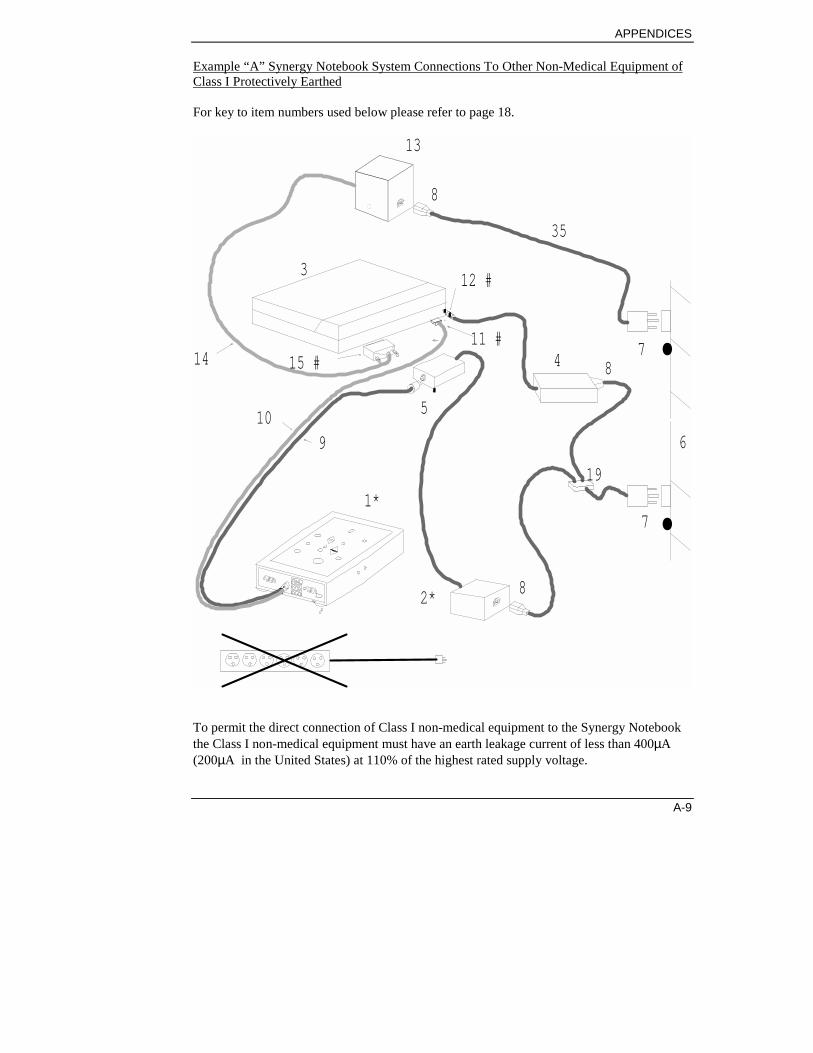
APPENDICES
A-9
Example “A” Synergy Notebook System Connections To Other Non-Medical Equipment ofClass I Protectively Earthed
For key to item numbers used below please refer to page 18.
.
.
13
8
312 #
11 #15 #14 4 8
7
6
19
7
5
910
1*
2* 8
35
To permit the direct connection of Class I non-medical equipment to the Synergy Notebookthe Class I non-medical equipment must have an earth leakage current of less than 400µA(200µA in the United States) at 110% of the highest rated supply voltage.

SYNERGY USER MANUAL
A-10
(Refer to Example B for connection of Class I non-medical equipment which exceeds theabove earth leakage current figures.)
Multiple portable socket outlets must not be used.
# Refer to Notebook PC user manual to determine the position of the input / outputconnectors.
* The Patient Interface Unit (PIU) must only be powered from the Synergy PowerSupply 035C005. The PIU must not be connected to any other power supply.
• Separate fixed mains socket outlets must be used

APPENDICES
A-11
Example “B” Synergy Notebook System Connections To Other Non-Medical Equipment ofClass I Protectively Earthed
For key to item numbers used below please refer to page 18.
.
.
8
13
8
12 #16
8
784
19
6
11#
5
15 #
910
14
3
1 *
2 *
7
38
36
If the other Class I non-medical equipment has an earth leakage current of greater than400µA (greater than 200µA in the United States) at 110% of the highest rated supply voltageit must be powered from a suitable mains isolation transformer with a floating secondarywinding, to reduce the earth leakage current below 400µA (200µA in the United States).

SYNERGY USER MANUAL
A-12
Multiple portable socket outlets must not be used.
# Refer to Notebook PC user manual to determine the position of the input / outputconnectors.
* The Patient Interface Unit (PIU) must only be powered from the Synergy PowerSupply 035C005. The PIU must not be connected to any other power supply.
• Separate fixed mains socket outlets must be used

APPENDICES
A-13
Example “C” Synergy Notebook System Connections To Other Non-Medical Equipment ofClass II Double Insulated
For key to item numbers used below please refer to page 18.
*
* .
.
18
88
16
36
4
37
12#3
14
109
11#
5
15#
8
7
7
82
1
6
35
38
In this situation, when other non-medical equipment of Class II is to be connected to SynergyNotebook, the system (that is Synergy notebook and the other Class II non-medicalequipment together) must not exceed the enclosure leakage current limit of 100µA.

SYNERGY USER MANUAL
A-14
To meet this requirement a suitable mains isolating transformer with a floating secondarywinding will be required to power the non-medical equipment including the Notebook PC.This transformer must have an enclosure leakage current of less than 75µA, that is the currentmeasured between the floating secondary winding of the isolation transformer and earth mustnot exceed 75µA. (The reduction from 100µA to 75µA makes allowance for the enclosureleakage current of the Synergy Notebook itself). If two or more non-medical equipments ofClass II are to be connected simultaneously to Synergy Notebook then all the items of non-medical equipment must be powered from a single mains isolating transformer to ensure thatthe enclosure leakage currents do not add and exceed the limit.
Multiple portable socket outlets must not be used.
# Refer to Notebook PC user manual to determine the position of the input / outputconnectors.
* The Patient Interface Unit (PIU) must only be powered from the Synergy PowerSupply 035C005. The PIU must not be connected to any other power supply.
• Separate fixed mains socket outlets must be used
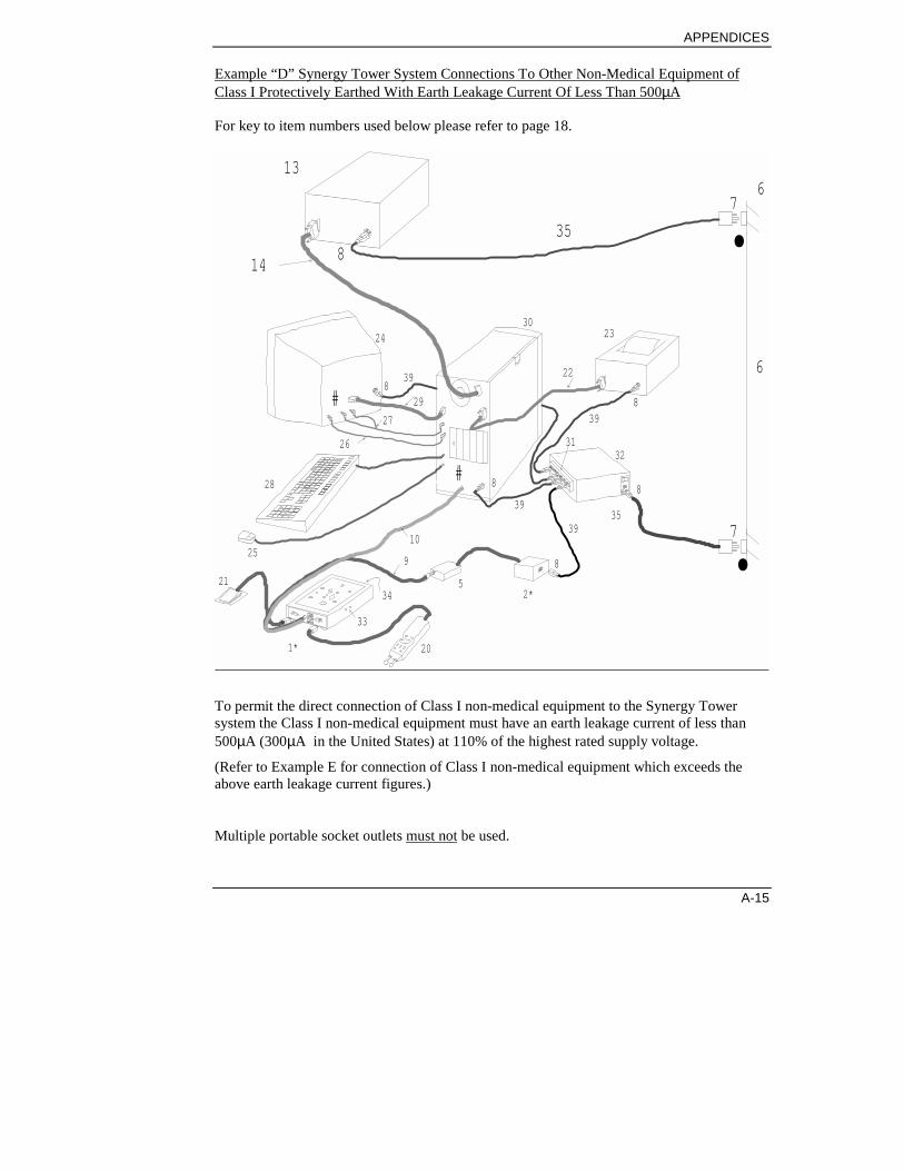
APPENDICES
A-15
Example “D” Synergy Tower System Connections To Other Non-Medical Equipment ofClass I Protectively Earthed With Earth Leakage Current Of Less Than 500µA
For key to item numbers used below please refer to page 18.
14
28
27
26
29
24
8
8
88
3132
30
5
10
925
20
21
33
34
1*
2*
3539
39
39
#
#
76
7
6
.
.
22
23
839
8
13
35
To permit the direct connection of Class I non-medical equipment to the Synergy Towersystem the Class I non-medical equipment must have an earth leakage current of less than500µA (300µA in the United States) at 110% of the highest rated supply voltage.
(Refer to Example E for connection of Class I non-medical equipment which exceeds theabove earth leakage current figures.)
Multiple portable socket outlets must not be used.

SYNERGY USER MANUAL
A-16
# Refer to PC Tower user manual to determine the position of the input / outputconnectors.
* The Patient Interface Unit (PIU) must only be powered from the Synergy PowerSupply 035C005. The PIU must not be connected to any other power supply.
• Separate fixed mains socket outlets must be used

APPENDICES
A-17
Example “E” Synergy Tower System Connections To Other Non-Medical Equipment ofClass I Protectively Earthed
For key to item numbers used below please refer to page 18.
14
28
27
26
29
24
8
8
88
3132
30
5
10
925
20
21
33
34
1*
2*
3539
39
39
#
#
76
7
6
.
.
22
23
839
8
13
16
838
39
If the other Class I non-medical equipment has an earth leakage current of greater than500µA (greater than 300µA in the United States) at 110% of the highest rated supply voltageit must be powered from a suitable mains isolation transformer with a floating secondarywinding, to reduce the earth leakage current below 500µA (300µA in the United States).
Multiple portable socket outlets must not be used.# Refer to PC Tower user manual to determine the position of the input / output
connectors.
* The Patient Interface Unit (PIU) must only be powered from the Synergy PowerSupply 035C005. The PIU must not be connected to any other power supply.
• Separate fixed mains socket outlets must be used

SYNERGY USER MANUAL
A-18
Key to Numbers used on the System Connection Drawings and on Examples A to E1 Patient Interface Unit (PIU)2 Synergy power supply3 Notebook PC4 Notebook PC power supply5 Junction box6 Wall of room7 Separate fixed mains socket outlets8 Mains inlet9 DC power to PIU10 USB cable11 To PC USB port12 DC power to Notebook PC13 Other non-medical equipment (Class I protectively earthed)14 Signal cable15 To appropriate PC connector16 Isolation transformer17 Isolated mains18 Other non-medical equipment (Class II double insulated)19 “Y” junction mains cable20 Deluxe Stimulator Probe (optional)21 Footswitch (optional)22 Signal to printer23 Oxford Instruments approved printer24 Oxford Instruments approved monitor25 Mouse26 Microphone signal27 Audio output28 Keyboard29 SVGA signal to monitor30 Oxford Instruments approved Tower PC31 Isolated mains outlets32 ISO-800 Isolation Transformer33 Internal stimulator output connectors34 Amplifier input connectors35 IEC socket to local mains connector (3 core 16AWG )36 Suitable cable to connect isolation transformer to other non-medical equipment37 Suitable cable to connect isolation transformer to Notebook PC power supply38 Suitable cable connecting local mains connector to input of isolation transformer39 IEC plug to IEC socket (connects isolated mains)40 Network direct connection – CAT5 shielded (STP) patch cable - crossover type with
RJ45 connectors41 Alternative printer connection42 Network card (PCMCIA- Ethernet)43 Media coupler for network

APPENDICES
A-19
Switching on
Warning: Switch ON before connecting patient electrodes.
Caution: All peripheral equipment (including the preamplifierand any external printer or keyboard) must be connected to theSynergy before the Synergy is switched ON.
Identify the plug on the mains lead which fits the connector onthe instrument and push it firmly into its socket on the rear panel.
Then connect the mains power plug to the mains electricitysupply and switch ON at the mains power plug.
The mains power ON/OFF switch for the instrument is a rockerswitch sited to the lower left hand side of the front of the unit.
Push the switch to the ON position:
The instrument is now ON and the screen displays a messageindicating that Windows 98 is starting. Once loaded the TestMenu will appear.
Switching off
Warning: Before switching OFF, disconnect all patientelectrodes.
Before switching OFF the instrument it is essential that theSynergy application and Windows 98 are closed down.
Failure to do this may result in loss of data and operatingproblems the next time the instrument is switched on.
Close down Synergy by selecting Exit Windows from the FILEmenu. Wait until the system has closed down before switchingoff the power plug.
If the instrument is to be switched OFF and ON again, waitapproximately 5 seconds before switching OFF and ON.
SYNERGY USER MANUAL
A-20
Special instructions for useSwitch ON the instrument before connecting patient electrodes
Disconnect all patient electrodes before switching OFF
Do NOT use electrical stimulators for the direct stimulation ofexposed nerves unless the stimulator output has been set to theLow range.
A patient with an implanted electronic device, for example acardiac pacemaker, should not be subjected to electricalstimulation unless specialist medical opinion has first beenobtained.
Accidental contact between electrodes connected to the amplifierand stimulator connectors, but not applied to the patient, andother conductive parts including protectively earthed partsshould be avoided.

APPENDICES
A-21
Electrical stimulating electrodesElectrical stimulators must be used only by appropriatelymedically trained and qualified personnel.
Electrodes must never be positioned so that electrical currentflows across the heart (trans-thoracic stimulation), i.e. neverapply a positive electrode to one limb and a negative electrode toany other limb. Keep the positive and negative stimulatingelectrode sites in close proximity.
When stimulating for long periods there may be a risk of damageto tissue under the stimulating electrodes due to the dccomponent in the stimulator output.
Surface electrodes must make good electrical contact with theskin surface.
WARNING! Connection of a patient to high frequencyelectrosurgical equipment and to Synergy simultaneously mayresult in burns at the sites of stimulating and recordingelectrodes. Damage may also occur to the electrical stimulatorand amplifiers, however Synergy includes protectioncomponents to reduce the risk of this happening.
WARNING! Operation of Synergy in close proximity (forexample 1 metre) to shortwave or microwave therapy equipmentmay produce instability in the electrical stimulator output.
NOTE: Current densities for any electrodes exceeding 2mAr.m.s./cm2 may require the special attention of the operator.
Note: Electrical stimulating electrodes supplied by themanufacturer can operate at the maximum output of theSynergy.

SYNERGY USER MANUAL
A-22
Electrical stimulus output of Synergy
Max intensity: 300V constant voltage (pulsed)
or
100mA constant current (pulsed)
High range: 0 - 300V or 0 - 100mA
Low range: 0 - 75V or 0 - 25mA
Max duration: 1ms per pulse
Max repetition rate: 10 pulses/second at ≤ 1ms
StimulatorsThe Stimulator can be either the internal one in the PIU, or anexternal Deluxe Stimulator Probe. The internal stimulator has1.5mm touchproof plugs at the side of the PIU. The DeluxeStimulator probe also has 1.5mm touchproof plugs or can befitted with the special probe head with built-in electrodes. Theprobe plugs into the back of the Patient Interface Unit via a2.4m/8ft lead.
To connect Deluxe Stimulator Probe toSynergy Notebook
Correctly align the plug with the socket on the PIU.
Firmly push home the plug and tighten the screws on either sideof the plug.
To disconnect the Deluxe StimulatorProbe
Unscrew the screws either side of the plug and pull firmly toseparate the connection.

APPENDICES
A-23
FootswitchThe foot control is attached via a socket on the PIU.
To connect to the Synergy
Correctly align the plug with the socket on the PIU.
Firmly push home the plug and tighten the screws on either sideof the plug.
To disconnect
Unscrew the screws either side of the plug and pull firmly toseparate the connection.
Printer
To connect the interface connectors
Firmly push home the connectors of the parallel port and thensecure them in place.
To disconnect the interface connectors
Release the securing mechanism (spring clips or screws) beforepulling apart the connections.
(Details of pin connections are found in Appendix B.)
Synergy should only be used with printers recommended byOxford Instruments.
For more information about installing your printer, see themanual which is provided with the printer.
Signal Cable
A high quality screened cable must be used when connecting aprinter to Synergy Notebook to ensure compliance with EMCregulations. Braid screened or double screened (braid plus foil)cables are the preferred types. The cable screen should make a360° connection to the screening shells of the connectors on eachend of the cable. Cables described as ‘IEEE 1284 compliant’ arelikely to be suitable.

SYNERGY USER MANUAL
A-24
Maintenance
After-sales service supportThe manufacturer of the Synergy and the distributors provide acomprehensive after-sales service support. For details, pleasecontact the manufacturer or your local distributor.
Service contracts are available.
A workshop manual is available for purchase containing all theinformation necessary to enable appropriately qualified technicalpersonnel to carry out repair and calibration of those parts of theequipment that are repairable.
Maintenance of the instrumentThe instrument is inherently reliable; it contains many solid-stateelectronic components which need no maintenance and no partsneed regular replacement.
Cleaning
Warning: Switch OFF and unplug the instrument beforecleaning with liquid.
The casing, panels and screen may be cleaned using a clothmoistened with water and detergent. Do not allow any liquid toenter the case of the instrument.
The instrument may also be cleaned using a low-pressure air-lineor a vacuum cleaner with an appropriate attachment.
Do not use propanone (acetone) on any part of the instrument.
The instrument must not be autoclaved or sterilised by anymeans.

APPENDICES
A-25
ElectrodesAn integral electrical stimulator and/or a remote electricalstimulator is provided with the instrument.
Oxford Instruments offer a comprehensive range ofneurodiagnostic accessories. Instructions for use Please requestour Neurodiagnostic Accessories Catalogue for full details.
Electrode kit supplied by the Synergymanufacturer
Stimulating electrodes
The stimulating electrodes in the EMG Electrode Kit aredesigned to deliver the maximum stimulus current available fromthe Synergy.
Usage and cleaning
Electrodes supplied by Oxford Instruments are accompanied byinstructions for use and these include recommendations forcleaning and sterilisation.


APPENDICES
B-1
Appendix BInterface ConnectionsThis information may be useful to some users of the instrument.
Full technical specifications are provided in the workshop manual which isavailable for purchase.
Signal CableHigh quality screened cables must be used when connecting to the interfaceconnectors of Synergy to ensure compliance with EMC regulations. Braidscreened or double screened (braid plus foil) cables are the preferred types. Thecable screen should make a 360° connection to the screening shells of theconnectors on each end of the cable.
Connectors on Notebook PC and PC TowerRefer to the user manuals for the Notebook PC and PC Tower.
Connectors on PIU
,#.,#.,#.,#. Stim A - Internal2 x Touchproof Sockets
Pin No. ServiceRed Stim +
Black Stim -

SYNERGY USER MANUAL
B-2
((((Stim B – Ext Deluxe
Stimulator Probe9 way D type socket
Pin No. Service1 +12V2 RS232 to STIM 13 RS232 from STIM 14 EMG positive trigger5 0V6 0V7 EMG negative trigger8 Stim OK9 Sync.
%Footswitch
9 way D type socketPin No. Service
1 N/C2 N/C3 Acquire4 N/C5 0V6 N/C7 N/C8 N/C9 N/C

APPENDICES
C-1
Appendix CTechnical Specifications
Amplifiers and FiltersInput Impedance 1000MΩ, < 30pFCMRR >110dBNoise < 0.7µV r.m.s (0.1 - 10kHz bandwidth, inputs
short circuited)Low Frequency ( -6dB/octave)
0.1, 1, 3, 10, 20, 100, 500HzHigh Frequency (-12dB/Octave)
100, 200, 500Hz1, 2, 3, 5, 10KHz
Notch Filter 50Hz or 60Hz or OFF
Data Acquisition and DisplayA-D Conversion 16 Bit ADCSweep Duration 10ms to 10s per channel (independent control
per channel)LongTrace™ facility Continuous acquisition of up to 100 x sweep
duration (1000s)Averager mode MeanArtefact Rejection Configurable per channelDisplay Sensitivity 0.01µV to 100mV/div
Electrical StimulatorSwitchable constant voltage or constant current with a low or high range.
Repetition Rates 0.5 to 10 pps. Fine and random controlStimulus Duration 0.05, 0.1, 0.2, 0.5, 1.0msOutput Type Constant Current or Constant VoltageRange High : 0 – 100mA, or 0 - 300V

SYNERGY USER MANUAL
C-2
Low range: 0 - 25mA, 0 - 75VDelay + 0 to 9 screen divisions
Dimensions (Patient Interface Unit)Size
156 x 55 x 241mm (6.2” x 2.2” x 9.5”)
Weight1 kg / 2.2lbs
Power RequirementsSynergy power supply 035C005
Input 100-240 V *50-60Hz
Approx. 70VA max
ISO800 Mains Isolating Transformer
Input 115V/230V *50-60Hz
840VA max

APPENDICES
C-3
Safety StandardsEN 60601-1:1990 inc. A1,A11,A12:1993;A2:1995 & A13:1996 UL2601-1 2nd
edition 1997 CAN/CSA22.2 No.601.1M90 inc S1-94 EN 60601-1-1:1993inc.A1:1996EN60601-2-40:1998
EMC StandardEN60601-1-2 :1993
Quality StandardsCE marked product in compliance with the Medical Devices Directive(93/42/EEC)Manufactured under approved Quality Management Systems - ISO 9001:1994,EN 46001:1993 and BS EN 46001:1994.TickIT approved procedures for software development.
Oxford Instruments Medical LtdManor Way, Old Woking, Surrey, GU22 9JU, U.K.Tel +44 01483 770331 Fax: +44 01483 727193
WEB: http://www.oxfordinstruments.com
Oxford Instruments Medical Inc.,12 Skyline Drive, Hawthorne, New York10532-2133 USATel: +1 914 593 7100 Fax: +1 914 593 72901-800-GET-TECA (438-8322)
WEB: http://www. oxfordinstruments.com
*Optional FeaturesOxford Instruments Medical Ltd reserves the right to change productspecification without notice, in line with our policy of constant productimprovement. EMG LivePlay™ and LongTrace™ are trademarks ofOxford Instruments Medical Ltd.
Microsoft Office and Windows are registered trademarks of MicrosoftCorporation.
Intel Pentium is a registered trademark of INTEL Corporation.


APPENDICES
D-1
Appendix DAssembling the NotebookStand
Assembly instructionsAttach the PC tray assembly to the pole using 3 blackcountersunk screws supplied
The PC tray can be attached so that the arm, when mounted, ispositioned on either the left or right.
Arm to left Arm to right

SYNERGY USER MANUAL
D-2
Attach the metal plate and cable clips
Turn the pole upside down and attach the plate for the powersupplies and cable clips.

APPENDICES
D-3
Attach the base to the pole using the large black boltsupplied
Attach the pole to the base, weights, and optionally the printertray.
If you are attaching the printer tray, position it so that its rubberfeet rest on the tops of two of the legs of the base. The printertray can be mounted at the front, side, or back of the stand.
When you have finished attaching these items, turn the standassembly upright again.

SYNERGY USER MANUAL
D-4
Attach the arm to the pole
Note
Before moving the stand between rooms, ensure that the arm islocked into position using the locking nuts.
Attach the Deluxe Stimulator Probe holder to the arm(optional) using 2 countersunk screws provided
Attach the power supplies to the stand
The power supplies incorporate a Velcro type pad for easyattachment and removal. They can be fitted to the metal plate onthe pole. Clean the plate using alcohol, remove the self-adhesivebacking from the pad, and press the pad firmly into position.Cables may then be routed up through the cable clips.
If you have the optional printer tray attached, there may be roomto mount the power supply at the back of it instead, if you prefer.
Attach the PIU to the plate at the end of the arm using thethree thumbscrews
Position Synergy Notebook on the top of the stand

APPENDICES
D-5
Put the Synergy Notebook on top of the PC tray, clean thecorners of the tray using alcohol, and attach the L-shaped self-adhesive rubber feet at the corners to secure it in place.
Connect cabling to the cable clips
See separate cabling diagram in Appendix A for systemconnections.
Excess cabling can be tucked onto the shelf under the PC.


APPENDICES
E-1
Appendix ECable management for theTower (Refer to page E-7 for a pull-out Key to the numbers)
3232
1
25 2824
30
X 1
X 4
X 4
Securing the isolated power supply

SYNERGY USER MANUAL
E-2
32
2
20
1
30
32
39
11
5
2
35
9 & 10
30
9
39
9 & 109 & 109 & 10
10
21
Cable management forPIU, Deluxe stim probeand power supply

APPENDICES
E-3
3
26
30
278
29
39
26
29
27
Management of monitor cables

SYNERGY USER MANUAL
E-4
4
2528
30
39
8
25289 & 10
39
Mouse and key board connections

APPENDICES
E-5
5
2330
39
8 22
39
Connecting the Printer to the Tower


APPENDICES
E-7

SYNERGY USER MANUAL
E-8
Key to Numbers used on the System Connection Drawings and on Examples A to E1 Patient Interface Unit (PIU)2 Synergy power supply3 Notebook PC4 Notebook PC power supply5 Junction box6 Wall of room7 Separate fixed mains socket outlets8 Mains inlet9 DC power to PIU10 USB cable11 To PC USB port12 DC power to Notebook PC13 Other non-medical equipment (Class I protectively earthed)14 Signal cable15 To appropriate PC connector16 Isolation transformer17 Isolated mains18 Other non-medical equipment (Class II double insulated)19 “Y” junction mains cable20 Deluxe Stimulator Probe (optional)21 Footswitch (optional)22 Signal to printer23 Oxford Instruments approved printer24 Oxford Instruments approved monitor25 Mouse26 Microphone signal27 Audio output28 Keyboard29 SVGA signal to monitor30 Oxford Instruments approved Tower PC31 Isolated mains outlets32 ISO-800 Isolation Transformer33 Internal stimulator output connectors34 Amplifier input connectors35 IEC socket to local mains connector (3 core 16AWG )36 Suitable cable to connect isolation transformer to other non-medical equipment37 Suitable cable to connect isolation transformer to Notebook PC power supply38 Suitable cable connecting local mains connector to input of isolation transformer39 IEC plug to IEC socket (connects isolated mains)40 Network direct connection – CAT5 shielded (STP) patch cable - crossover type with
RJ45 connectors41 Alternative printer connection42 Network card (PCMCIA- Ethernet)43 Media coupler for network
INDEX
Index 1
Index+ / - switch (Trigger Rising / Falling
Edge).................................................10Access levels.........................................18Acquire ON switch .................................9Acquire Single switch .............................9Acquiring the data
Blink reflex test...............................109Motor NCS test ...........................76, 82Repetitive Nerve Stim test ..............103
Acquisition setup ..................................63Adding comments .................................39After-sales service support (App A) .....24After-sales support ................................16Artefact Reject setup.............................65Audio setup ...........................................65Automatic marker placement ..............143Blink Reflex test .................................108Cable management for the Tower (App E)
............................................................1Cables (App A) .......................................7Cancelling a search ...............................34Change trace duration ...................60, 145Change trace sensitivity ................60, 145Changing a password ............................54Changing paths .....................................54Changing your User setup.....................53Channel settings ....................................63Cleaning (App A)..................................24Clinical overview
Blink reflex test...............................108Fibre Density Analysis test .............135F-Wave test .......................................87H-Reflex test .....................................92Interference Pattern Analysis test....113Macro EMG test..............................138Motor NCS test .................................74Multi-MUP Analysis test ................118Needle EMG test...............................95Repetitive Nerve Stim test ..............102Sensory NCS test ..............................81Single Fibre Jitter test .....................124
Comments .............................................42Comments utility...................................38
Comments, adding................................ 39Compare ............................................. 145Comparing results................................SeeComponents............................................ 1Components of the GUI ....................... 15Components of the Synergy Suite .......... 8Components of the Synergy Tower ........ 6Configuring and displaying results..... 149Configuring protocols........................... 59Configuring tests .................................. 20Configuring the network ...................... 56Configuring the protocols..................... 61Configuring the Results Table............ 151Configuring the system ........................ 47Configuring the System........................ 18Connecting the electrodes
Blink reflex test .............................. 108Fibre Density Analysis test............. 135F-Wave test ...................................... 88H-Reflex test .................................... 92Macro EMG test ............................. 139Motor NCS test................................. 75Needle EMG test .............................. 96Repetitive Nerve Stim test.............. 103SFJ test ....................................124, 130
Connecting the equipment (App A) ....... 7Creating a new protocol ....................... 62Custom result...................................... 152Custom Tables...................................... 46Customising the report layout .............. 42Database ............................................... 19Defining a muscle list........................... 55Defining host and satellite .................... 48Defining the report sequence................ 45Deleting a patient.................................. 27Deleting a user...................................... 52Deleting results..................................... 33Disposal of equipment........................... xiEditing a protocol ................................. 62Editing a user's setup ............................ 51Editing and saving a report................... 41Electrical interference suppression........ xi

SYNERGY USER MANUAL
Index 2
Electrical stimulating electrodes (App A)..........................................................21
Electrical Stimulator setup ....................67Electrodes (App A) .........................21, 25Electronic Mail......................................16E-mail....................................................16E-mail program
Configuring .......................................49Entering patient information .................23Erase switch ............................................9Exporting patient and report data..........35Fibre Density Analysis test .................135Filter settings setup ...............................63Footswitch.......................................11, 23
Connecting (App A)..........................23Function Key Bar..................................15Function keys ........................................15F-Wave test ...........................................87Generating reports.................................37Generating Reports ...............................21Getting support .....................................16Graphs.......................................42, 80, 86GUI .......................................................15Handling patient information ................23Header file.............................................42
Selecting and defining.......................43Host and satellite
configuring........................................48H-Reflex test .........................................92Importing patient and report data..........36Inserting page breaks ............................45Installation and maintenance (App A) ....1Interface connections (App B) ................1Interference Pattern Analysis test........113List of controls ........................................9Logging on............................................14Macro EMG test..................................138Maintenance (App A) ...........................24Manual marking of traces ...................144Marker placement ...............................143Marker setup .......................................144Marker toolbar ....................................144MedPad ...........................................39, 46Menu Bar ..............................................15Motor NCS Test....................................74Moving a trace ....................................143Multi-MUP Analysis test ....................118Muscle configuration ............................55Muscle list, definition ...........................55
Needle EMG test .................................. 95Network configuration.......................... 56Next switch........................................... 10Notch filter setting................................ 49Obtaining a report online...................... 38On-line configuration ........................... 59Online report ........................................ 39Online reporting ................................... 38Opening a report................................... 41Opening and closing folders................. 16Opening the Test Catalog ..................... 31Overview of the system.......................... 1Page breaks........................................... 45Parts of the system.................................. 1Password
Changing .......................................... 54Paths
Changing .......................................... 54Patient
Deleting details................................. 27Entering and saving details............... 24Recalling..................................... 27, 31Reviewing results and reports .......... 31transferring data between systems.... 28
Patient dataexporting........................................... 35
Patient Database ................................... 19Patient demographics
Configuring ...................................... 50Patient details ....................................... 23
Searching on ..................................... 34Patient information ............................... 23
Entering ............................................ 23Retrieving ......................................... 27Saving............................................... 23Searching for .................................... 34
Patient Interface Unit.............................. 9Patient List............................................ 27Patient Table......................................... 42Power supply connections (App A)........ 2Printer
Connecting (App A) ......................... 23Printing a report.................................... 46Protocol
Creating ............................................ 62Editing .............................................. 62
Protocol Configuration Wizard ............ 61Protocol Table setup....................... 68, 69Protocols

INDEX
Index 3
On-line configuration........................59Selecting............................................73
Protocols configuration.........................59QEMG tests.................................113, 118Recalling a patient...........................27, 31Recalling a report..................................41Recalling results....................................33Recompiling a report ............................39Reference values ...........................68, 150Repetitive Nerve Stimulation test .......102Report
Editing and saving.............................41Opening.............................................41Recalling ...........................................41Recompiling......................................39Viewing.......................................38, 39
Report dataexporting ...........................................35
Report layout, customising ...................42Report sequence, defining.....................45Report Setup ...................................39, 42Reporting ..............................................21Reports ............................................21, 37
Printing..............................................46Result Mode........................................149Result Tables.........................................42Results...................................................38
Configuring.....................................149Deleting.............................................33Displaying.......................................149Recalling ...........................................33Sorting.........................................79, 85Viewing.............................................33
Results available . 79, 85, 90, 94, 100, 106Results information...............................31Results Table...............................149, 151Retrieving patient information ..............27Reviewing results for a patient..............31Safety ..................................................... ixSaving patient information....................23Search, cancelling .................................34Searching for patient information .........34Selecting a notch filter setting...............49Selecting a protocol ..............................73Selecting a trace ..................................142Selecting an online report .....................39Selecting the test ...................................73Sensitivity settings setup.......................63Sensitivity switch..................................10
Sensory NCS test.................................. 81Setting up a new user............................ 50SFJ test ............................................... 124SFJ tests...............................124, 135, 138Signature file ........................................ 42
Selecting and defining ...................... 44Single Fibre Jitter test......................... 124Softkeys................................................ 15Sorting results..................................79, 85Sources of artefact ................................ xiiSpecifications (App C) ........................... 1Stim Duration switch............................ 10Stim Intensity switch ............................ 10Stim switch........................................... 10Stimulators (App A) ............................. 22Support ................................................. 16Sweep Duration switch......................... 10Switching off the system (App A)........ 19Switching on the system (App A) ........ 19Symbols.......................................... ix, xivSympathetic Skin Response test ......... 112Synergy................................................... 1Synergy Reader software...................... 17Synergy Suite ......................................... 8Synergy Tower ....................................... 6Synergy, using...................................... 14System configuration............................ 47System overview .................................... 1Technical specifications (App C) ........... 1Temperature probe ......................5, 6, 154Test Navigator / Test History screens.. 16Test Catalog.....................................31, 40Test Menu screen.................................. 23Test Report settings .............................. 45Test Report Settings ............................. 42Tests ................................................20, 71
Blink reflex..................................... 108Fibre Density Analysis ................... 135F-Wave ............................................. 87H-Reflex ........................................... 92Interference Pattern Analysis ......... 113Macro EMG.................................... 138Motor NCS ....................................... 74Multi-MUP Analysis ...................... 118Needle EMG..................................... 95Repetitive Nerve Stimulation ......... 102Selecting ........................................... 73Sensory NCS .................................... 81SFJ.................................................. 124

SYNERGY USER MANUAL
Index 4
Single Fibre Jitter ............................124Sympathetic skin response ..............112Typical procedure .............................72Using.................................................71
The tests ................................................71Title Bar ................................................15Toolbar..................................................15Trace analysis and display ..................142Trace arithmetic ..................................146Trace duration ...............................60, 145Trace sensitivity ............................60, 145Traces
Manual marking ..............................144Moving............................................143
Transferring patient information ...........28Units used ........... 80, 86, 90, 94, 101, 106
User Configuration ............................... 53User interface ....................................... 15User setup....................................... 50, 53
Changing .......................................... 53User setup, editing................................ 51User, deletion ....................................... 52Using Synergy ...................................... 14Using the patient database .................... 19Using the tests ...................................... 71View All button.................................... 66Viewing a report................................... 39Visit details..................................... 23, 25
Entering and saving .......................... 25Volume switch...................................... 10Wizards ................................................ 61