Manual EHP-L - adbsafegate.com
44
EHP-L LED Elevated Heliport/ Helipad Perimeter Light User Manual 96A0407, Rev. F, 2019/10/21
Transcript of Manual EHP-L - adbsafegate.com

EHP-LLED Elevated Heliport/ Helipad Perimeter Light
User Manual96A0407, Rev. F, 2019/10/21


A.0 Disclaimer / Standard Warranty
CE certification
The equipment listed as CE certified means that the product complies with the essential requirements concerning safety andhygiene. The directives that have been taken into consideration in the design are available on written request to ADBSAFEGATE.
ETL certification
The equipment listed as ETL certified means that the product complies with the essential requirements concerning safety andFAA Airfield regulations. The directives that have been taken into consideration in the design are available on written requestto ADB SAFEGATE.
LED Product Guarantee
Where applicable, per FAA EB67 (applicable edition), ADB SAFEGATE L858(L) Airfield Guidance Signs are warranted againstelectrical defects in design or manufacture of the LED or LED specific circuitry for a period of 4 years. ADB SAFEGATE LED lightfixtures (with the exception of obstruction lighting) are warranted against mechanical and physical defects in design ormanufacture for a period of 12 months from date of installation; and are warranted against electrical defects in design ormanufacture of the LED or LED specific circuitry for a period of 4 years per FAA EB67 (applicable edition).
NoteSee your sales order contract for a complete warranty description. In some specific cases, deviations are (to be)accepted in the contract, which will supersede the standard warranty.
Standard Product Guarantee
Products of ADB SAFEGATE manufacture are guaranteed against mechanical, electrical, and physical defects (excluding lamps)which may occur during proper and normal use for a period of one year from the date of installation or 2 years from date ofshipment and are guaranteed to be merchantable and fit for the ordinary purposes for which such products are made. ADBSAFEGATE L858 Airfield Guidance Signs are warranted against mechanical and physical defects in design or manufacture for aperiod of 2 years from date of installation per FAA AC 150/5345-44 (applicable edition).
NoteSee your sales order contract for a complete warranty description.
All Products Guarantee
LED Products of ADB SAFEGATE, manufactured and sold by ADB SAFEGATE or its licensed representatives, meets thecorresponding requirements of FAA, ICAO and IEC.
ADB SAFEGATE will correct by repair or replacement per the applicable guarantee above, at its option, equipment or partswhich fail because of mechanical, electrical or physical defects, provided that the goods have been properly handled andstored prior to installation, properly installed and properly operated after installation, and provided further that Buyer givesADB SAFEGATE written notice of such defects after delivery of the goods to Buyer. Refer to the Safety section for moreinformation on Material Handling Precautions and Storage precautions that must be followed.
ADB SAFEGATE reserves the right to examine goods upon which a claim is made. Said goods must be presented in the samecondition as when the defect therein was discovered. ADB SAFEGATE furthers reserves the right to require the return of suchgoods to establish any claim.
ADB SAFEGATE’s obligation under this guarantee is limited to making repair or replacement within a reasonable time afterreceipt of such written notice and does not include any other costs such as the cost of removal of defective part, installationof repaired product, labor or consequential damages of any kind, the exclusive remedy being to require such new parts to befurnished.
96A0407, Rev. F, 2019/10/21 iiiCopyright © ADB Safegate, All Rights Reserved

ADB SAFEGATE’s liability under no circumstances will exceed the contract price of goods claimed to be defective. Any returnsunder this guarantee are to be on a transportation charges prepaid basis. For products not manufactured by, but sold by ADBSAFEGATE, warranty is limited to that extended by the original manufacturer.
This is ADB SAFEGATE’s sole guarantee and warranty with respect to the goods; there are no express warranties or warrantiesof fitness for any particular purpose or any implied warranties of fitness for any particular purpose or any implied warrantiesother than those made expressly herein. All such warranties being expressly disclaimed.
Liability
WARNINGUse of the equipment in ways other than described in the catalogue leaflet and the manual may result in personalinjury, death, or property and equipment damage. Use this equipment only as described in the manual.
ADB SAFEGATE cannot be held responsible for injuries or damages resulting from non-standard, unintended uses of itsequipment. The equipment is designed and intended only for the purpose described in the manual. Uses not described in themanual are considered unintended uses and may result in serious personal injury, death or property damage.
Unintended uses includes the following actions:
• Making changes to equipment that have not been recommended or described in this manual or using parts that are notgenuine ADB SAFEGATE replacement parts or accessories.
• Failing to make sure that auxiliary equipment complies with approval agency requirements, local codes, and all applicablesafety standards if not in contradiction with the general rules.
• Using materials or auxiliary equipment that are inappropriate or incompatible with your ADB SAFEGATE equipment.
• Allowing unskilled personnel to perform any task on or with the equipment.
© ADB SAFEGATE BVBA
This manual or parts thereof may not be reproduced, stored in a retrieval system, or transmitted, in any form or by any means,electronic, mechanical, photocopying, recording, nor otherwise, without ADB SAFEGATE BVBA’s prior written consent.
This manual could contain technical inaccuracies or typographical errors. ADB SAFEGATE BVBA reserves the right to revise thismanual from time to time in the contents thereof without obligation of ADB SAFEGATE BVBA to notify any person of suchrevision or change. Details and values given in this manual are average values and have been compiled with care. They are notbinding, however, and ADB SAFEGATE BVBA disclaims any liability for damages or detriments suffered as a result of relianceon the information given herein or the use of products, processes or equipment to which this manual refers. No warranty ismade that the use of the information or of the products, processes or equipment to which this manual refers will not infringeany third party’s patents or rights. The information given does not release the buyer from making their own experiments andtests.
EHP-L
ivCopyright © ADB Safegate, All Rights Reserved

TABLE OF CONTENTS
1.0 Safety.........................................................................................................................................................................................11.1 Safety Messages.......................................................................................................................................................................................................... 1
1.1.1 Introduction to Safety...................................................................................................................................................................................21.1.2 Intended Use.................................................................................................................................................................................................... 21.1.3 Material Handling Precautions: Storage................................................................................................................................................ 31.1.4 Material Handling Precautions: Fasteners.............................................................................................................................................31.1.5 Operation Safety.............................................................................................................................................................................................41.1.6 Maintenance Safety....................................................................................................................................................................................... 41.1.7 Material Handling Precautions, ESD........................................................................................................................................................51.1.8 Arc Flash and Electric Shock Hazard........................................................................................................................................................5
2.0 EHP-L ........................................................................................................................................................................................ 72.1 About this manual ..................................................................................................................................................................................................... 7
2.1.1 Introduction .....................................................................................................................................................................................................72.1.2 How to work with the manual ..................................................................................................................................................................7
2.2 Product Introduction .................................................................................................................................................................................................72.2.1 LED Elevated Heliport Perimeter Light................................................................................................................................................... 82.2.2 EHP-L Fixture: Required Equipment .....................................................................................................................................................11
3.0 Installation .............................................................................................................................................................................133.1 Unpacking ...................................................................................................................................................................................................................133.2 Assembly Instructions ............................................................................................................................................................................................133.3 J-Box Mounting Installation .................................................................................................................................................................................133.4 FAA L867 Light Base Installation ........................................................................................................................................................................143.5 FAA Stake Mounting Installation ....................................................................................................................................................................... 15
3.5.1 Conduit Mounting Instructions ............................................................................................................................................................. 16
4.0 Maintenance .......................................................................................................................................................................... 19
5.0 Troubleshooting ....................................................................................................................................................................215.1 Repair ............................................................................................................................................................................................................................21
5.1.1 Lens Replacement .......................................................................................................................................................................................215.2 LED Assembly Replacement ................................................................................................................................................................................ 22
5.2.1 LED PCB Assembly Replacement .......................................................................................................................................................... 23
6.0 EHP Parts ................................................................................................................................................................................256.1 Spare Components ..................................................................................................................................................................................................26
A.0 SUPPORT................................................................................................................................................................................ 31A.1 ADB SAFEGATE website..........................................................................................................................................................................................31A.2 Recycling......................................................................................................................................................................................................................32
A.2.1 Local authority recycling...........................................................................................................................................................................32A.2.2 ADB SAFEGATE recycling.......................................................................................................................................................................... 32
96A0407, Rev. F, 2019/10/21 vCopyright © ADB Safegate, All Rights Reserved

EHP-LTABLE OF CONTENTS
viCopyright © ADB Safegate, All Rights Reserved

List of Figures
Figure 1: EHP-L Assembly (direct J-Box mounting shown) ........................................................................................................................................ 8
Figure 2: FAA L-867 Light Base Installation (series circuit) .......................................................................................................................................15
Figure 3: Stake Mounting Installation .............................................................................................................................................................................. 16
Figure 4: Conduit Mounting Installation. ........................................................................................................................................................................17
Figure 5: Lens Attachment Ring ..........................................................................................................................................................................................22
Figure 6: Enclosure Set Screw Location ........................................................................................................................................................................... 22
Figure 7: Bottom Enclosure Screws ................................................................................................................................................................................... 23
Figure 8: PCB LED Disconnect ............................................................................................................................................................................................. 23
Figure 9: PCB Assembly Mounting Screws .....................................................................................................................................................................24
Figure 10: EHP-L Component Identification ..................................................................................................................................................................26
Figure 11: EHP-L Assembly ...................................................................................................................................................................................................28
Figure 12: Assembly ................................................................................................................................................................................................................ 29
Figure 13: Current Driven Enclosure ................................................................................................................................................................................. 30
96A0407, Rev. F, 2019/10/21 viiCopyright © ADB Safegate, All Rights Reserved

EHP-LList of Figures
viiiCopyright © ADB Safegate, All Rights Reserved
List of Tables
Table 1: EHP-L Fixtures ..............................................................................................................................................................................................................7
Table 2: Required Equipment Supplied ............................................................................................................................................................................11
Table 3: Required Equipment Not Supplied ...................................................................................................................................................................11
Table 4: Isolation Transformers ........................................................................................................................................................................................... 12
Table 5: EHP-L Light Fixture Maintenance ...................................................................................................................................................................... 19
Table 6: ADB SAFEGATE Support.........................................................................................................................................................................................31
96A0407, Rev. F, 2019/10/21 ixCopyright © ADB Safegate, All Rights Reserved
EHP-LList of Tables
xCopyright © ADB Safegate, All Rights Reserved

1.0 Safety
Introduction to Safety
This section contains general safety instructions for installing and using ADB SAFEGATE equipment. Some safety instructionsmay not apply to the equipment in this manual. Task- and equipment-specific warnings are included in other sections of thismanual where appropriate.
1.1 Safety Messages
HAZARD Icons used in the manual
For all HAZARD symbols in use, see the Safety section. All symbols must comply with ISO and ANSI standards.
Carefully read and observe all safety instructions in this manual, which alert you to safety hazards and conditions that mayresult in personal injury, death or property and equipment damage and are accompanied by the symbol shown below.
WARNINGFailure to observe a warning may result in personal injury, death or equipment damage.
DANGER - Risk of electrical shock or ARC FLASHDisconnect equipment from line voltage. Failure to observe this warning may result in personal injury, death, orequipment damage. ARC Flash may cause blindness, severe burns or death.
WARNING - Wear personal protective equipmentFailure to observe may result in serious injury.
WARNING - Do not touchFailure to observe this warning may result in personal injury, death, or equipment damage.
CAUTIONFailure to observe a caution may result in equipment damage.
Qualified Personnel
Important InformationThe term qualified personnel is defined here as individuals who thoroughly understand the equipment and its safeoperation, maintenance and repair. Qualified personnel are physically capable of performing the required tasks, familiarwith all relevant safety rules and regulations and have been trained to safely install, operate, maintain and repair theequipment. It is the responsibility of the company operating this equipment to ensure that its personnel meet theserequirements.Always use required personal protective equipment (PPE) and follow safe electrical work practice.
96A0407, Rev. F, 2019/10/21 1Copyright © ADB Safegate, All Rights Reserved

1.1.1 Introduction to Safety
CAUTIONUnsafe Equipment UseThis equipment may contain electrostatic devices, hazardous voltages and sharp edges on components
• Read installation instructions in their entirety before starting installation.• Become familiar with the general safety instructions in this section of the manual before installing,
operating, maintaining or repairing this equipment.• Read and carefully follow the instructions throughout this manual for performing specific tasks and
working with specific equipment.• Make this manual available to personnel installing, operating, maintaining or repairing this
equipment.• Follow all applicable safety procedures required by your company, industry standards and
government or other regulatory agencies.• Install all electrical connections to local code.• Use only electrical wire of sufficient gauge and insulation to handle the rated current demand. All
wiring must meet local codes.• Route electrical wiring along a protected path. Make sure they will not be damaged by moving
equipment.• Protect components from damage, wear, and harsh environment conditions.• Allow ample room for maintenance, panel accessibility, and cover removal.• Protect equipment with safety devices as specified by applicable safety regulations• If safety devices must be removed for installation, install them immediately after the work is
completed and check them for proper functioning prior to returning power to the circuit.
Failure to follow this instruction can result in serious injury or equipment damage
Additional Reference Materials
Important Information
• IEC - International Standards and Conformity Assessment for all electrical, electronic and related technologies.
• IEC 60364 - Electrical Installations in Buildings.
• FAA Advisory: AC 150/5340-26 (current edition), Maintenance of Airport Visual Aid Facilities.
• Maintenance personnel must refer to the maintenance procedure described in the ICAO Airport Services Manual,Part 9.
• ANSI/NFPA 79, Electrical Standards for Metalworking Machine Tools.
• National and local electrical codes and standards.
1.1.2 Intended Use
CAUTIONUse this equipment as intended by the manufacturerThis equipment is designed to perform a specific function, do not use this equipment for other purposes
• Using this equipment in ways other than described in this manual may result in personal injury, deathor property and equipment damage. Use this equipment only as described in this manual.
Failure to follow this instruction can result in serious injury or equipment damage
EHP-LSafety
2Copyright © ADB Safegate, All Rights Reserved

1.1.3 Material Handling Precautions: Storage
CAUTIONImproper StorageStore this equipment properly
• If equipment is to be stored prior to installation, it must be protected from the weather and kept freeof condensation and dust.
Failure to follow this instruction can result in equipment damage
1.1.4 Material Handling Precautions: Fasteners
DANGERForeign Object Damage - FODThis equipment may contain fasteners that may come loose - torque properly.
• Only use fasteners of the same type as the one originally supplied with the equipment.• Use of incorrect combination of gaskets, bolts and nuts can create severe damages to the product
installation and create safety risk .• You need to know what base the light fixture will be installed in, in order to chose the correct gasket,
bolts and nuts.• Bolt type, length, and torque value are determined by type of base, height of spacers used, and clamp
force required in FAA Engineering Brief No 83 (latest revision).• Due to the risk of bolts vibrating loose, do not use any type of washer with the fixing bolts (such as
split lock washers) other than an anti-vibration washer. Anti-vibration washers as defined in FAA EB83 (latest edition) must be used. For installations other than FAA, use the base can manufacturer'srecommendations.
• Always tighten the fasteners to the recommended torque. Use a calibrated torque wrench and applythe recommended adhesive type.
• Obey the instructions of the adhesives necessary for the fasteners.
Failure to follow these warnings may cause the fasteners to loosen, damage the equipment,potentially to loosen the equipment. This can lead to a highly dangerous situation of FOD, withpotential lethal consequences.
NoteTo minimize the risk of errors, the ADB SAFEGATE Sales Representative will have information on which gasket goeswith which base. This information is also provided in the product Data sheets, the User Manuals and the Spare PartLists.
CAUTIONUse of incorrect combination of gaskets, bolts and nuts can create severe damages to the product installation andcreate multiple safety risks.To obtain a safe and watertight installation the O-ring and retaining bolt stated in the document must be used.You need to know what base the light fixture will be installed in, in order to choose the correct gasket, bolts and nuts.Failure to follow these cautions can result in equipment damage or aircraft FOD.
96A0407, Rev. F, 2019/10/21 3Copyright © ADB Safegate, All Rights Reserved

1.1.5 Operation Safety
CAUTIONImproper OperationDo Not Operate this equipment other than as specified by the manufacturer
• Only qualified personnel, physically capable of operating the equipment and with no impairments intheir judgment or reaction times, should operate this equipment.
• Read all system component manuals before operating this equipment. A thorough understanding ofsystem components and their operation will help you operate the system safely and efficiently.
• Before starting this equipment, check all safety interlocks, fire-detection systems, and protectivedevices such as panels and covers. Make sure all devices are fully functional. Do not operate thesystem if these devices are not working properly. Do not deactivate or bypass automatic safetyinterlocks or locked-out electrical disconnects or pneumatic valves.
• Protect equipment with safety devices as specified by applicable safety regulations.• If safety devices must be removed for installation, install them immediately after the work is
completed and check them for proper functioning.• Route electrical wiring along a protected path. Make sure they will not be damaged by moving
equipment.• Never operate equipment with a known malfunction.• Do not attempt to operate or service electrical equipment if standing water is present.• Use this equipment only in the environments for which it is rated. Do not operate this equipment in
humid, flammable, or explosive environments unless it has been rated for safe operation in theseenvironments.
• Never touch exposed electrical connections on equipment while the power is ON.
Failure to follow these instructions can result in equipment damage
1.1.6 Maintenance Safety
DANGERElectric Shock HazardThis equipment may contain electrostatic devices
• Do not operate a system that contains malfunctioning components. If a component malfunctions,turn the system OFF immediately.
• Disconnect and lock out electrical power.• Allow only qualified personnel to make repairs. Repair or replace the malfunctioning component
according to instructions provided in its manual.
Failure to follow these instructions can result in death or equipment damage
EHP-LSafety
4Copyright © ADB Safegate, All Rights Reserved
1.1.7 Material Handling Precautions, ESD
CAUTIONElectrostatic Sensitive DevicesThis equipment may contain electrostatic devices
• Protect from electrostatic discharge.• Electronic modules and components should be touched only when this is unavoidable e.g. soldering,
replacement.• Before touching any component of the cabinet you shall bring your body to the same potential as the
cabinet by touching a conductive earthed part of the cabinet.• Electronic modules or components must not be brought in contact with highly insulating materials
such as plastic sheets, synthetic fiber clothing. They must be laid down on conductive surfaces.• The tip of the soldering iron must be grounded.• Electronic modules and components must be stored and transported in conductive packing.
Failure to follow this instruction can result in equipment damage
1.1.8 Arc Flash and Electric Shock Hazard
DANGERSeries Circuits have Hazardous VoltagesThis equipment produces high voltages to maintain the specified current - Do NOT Disconnect whileenergized.
• Allow only qualified personnel to perform maintenance, troubleshooting, and repair tasks.• Only persons who are properly trained and familiar with ADB SAFEGATE equipment are permitted to
service this equipment.• An open airfield current circuit is capable of generating >5000 Vac and may appear OFF to a meter.• Never unplug a device from a constant current circuit while it is operating; Arc flash may result.• Disconnect and lock out electrical power.• Always use safety devices when working on this equipment.• Follow the recommended maintenance procedures in the product manuals.• Do not service or adjust any equipment unless another person trained in first aid and CPR is present.• Connect all disconnected equipment ground cables and wires after servicing equipment. Ground all
conductive equipment.• Use only approved ADB SAFEGATE replacement parts. Using unapproved parts or making
unapproved modifications to equipment may void agency approvals and create safety hazards.• Check the interlock systems periodically to ensure their effectiveness.• Do not attempt to service electrical equipment if standing water is present. Use caution when
servicing electrical equipment in a high-humidity environment.• Use tools with insulated handles when working with airfield electrical equipment.
Failure to follow these instructions can result in death or equipment damage
96A0407, Rev. F, 2019/10/21 5Copyright © ADB Safegate, All Rights Reserved

EHP-LSafety
6Copyright © ADB Safegate, All Rights Reserved

2.0 EHP-L
The EHP-L LED fixture is intended for general aviation use as a heliport perimeter light. The green and yellow omni-directionallight is used to define the perimeter of the area the helicopter requires for touchdown and lift-off (TLOF).Yellow heliport lightsare typically used on existing applications, while green lights are typically used for new applications. The 95-264V AC,50/60Hz power supply minimizes installation costs by reducing required number of cable runs. Overall height installed is lessthan 8 inches, complying with AC 150/5390-2 requirements for raised perimeter lights.
2.1 About this manual
2.1.1 IntroductionThis manual shows the information necessary to:
• Install and maintain the EHP-L equipment.
2.1.2 How to work with the manual
1. Become familiar with the structure and content.
2. Carry out the actions completely and in the given sequence.
2.2 Product Introduction
See Figure 1. This section describes the LED, omni-directional elevated light fixture for heliport/helipad perimeter light. Thesefixtures are designed to provide definition to the edges of the helipad required for touchdown and lift-off (TLOF) per FAA AC150/5390-2.
The light fixture is available for direct mounting to helipad using a J-Box. Optional designs are available for mounting to a FAAL- 867 baseplate with a frangible coupling, with or without a column to increase the mounting height of the fixture. The EHP-L can also be stake or conduit mounted. The fixture is available in both voltage (95-264 Vac, 50-60Hz) and current driven (2.8- 6.6A, 50 - 60 Hz) designs. The unit can also be supplied with an arctic kit per FAA Engineering Brief 67.
Designed according to AC 150/5390-2 Heliport Design. L-861T AC 150/5345-46 (Current Edition) and the FAA EngineeringBrief No. 67 for LED Performance. The optics exceed the lighting requirements of ANSI/IEEE C62.41 - 1991.
Table 1: EHP-L FixturesLight Fixture Function
Yellow Perimeter Light – Existing Installations and Military
Green Perimeter Light – New Installations
Blue Lead-in Taxiway Applications
96A0407, Rev. F, 2019/10/21 7Copyright © ADB Safegate, All Rights Reserved

NoteFAA AC 150/5390-2, requires heliport perimeter lights to be green.
Figure 1: EHP-L Assembly (direct J-Box mounting shown)
The light fixtures are available in yellow for existing civil and military applications and in green for new applications. Blue isavailable for lead-in taxiway applications. The basic design is 8-inches in height for direct installation using a J-Box ( junctionbox). The J-Box is supplied with 4 ports that are tapped for ¾" NPT for conduit connections. The J-box is directly mounted tothe helipad. See FAA AC 150/5340-30 and AC 150/5390-2 for the location and installation instructions for mounting theperimeter light.
2.2.1 LED Elevated Heliport Perimeter Light
Compliance with Standards
FAA: Designed according to AC 150/5390-2 Heliport Design. L-861T AC 150/5345-46 (Current Edition) and the FAAEngineering Brief No. 67. ETL Certified (L-861T).
Uses
EHP is intended for use as a heliport perimeter light. The green and yellow omnidirectional light is used to define theperimeter of the area the helicopter requires for touchdown and lift-off (TLOF).
• Yellow EHPs are typically used on military applications
• Green EHPs are typically used for new civil applications
• Blue EHPs can be used for lead-in taxiway applications
Features
• Overall height installed is less than 8 inches, complying with AC 150/5390-2C requirements for raised perimeter lights
• Average individual LED life of 50,000 hours (minimum)
• 95-264 VAC, 50/60 Hz power supply minimizes installation costs by reducing required cable run wire size. Light outputstays constant regardless of input voltage range.
EHP-LEHP-L
8Copyright © ADB Safegate, All Rights Reserved

• EHP with arctic option (U.S. Patent 7192155 B2) uses a thermostatically controlled heater to prevent ice and snow buildupfrom obscuring light output. Melts ice similar to traditional incandescent fixtures.
• Thermostatically controlled heater cycles on and off when temperature drops below freezing, reducing overall energyconsumption
• For voltage-driven applications, the EHP with a thermostatically controlled arctic option is 2.6 times more efficient in warmweather operations and 1.5 times more efficient than a typical 54 W(VA) fixture in cold weather operations
• More than 500,000 ADB Safegate elevated LED fixtures are in use around the USA
• Direct replacement for incandescent fixtures
• Fixture uses aluminum casting, stainless steel hardware, and is protected with aviation yellow powder coat finish
• All parts are corrosion-resistant
• Rugged, low-profile design reduces the potential for damage in the FATO perimeter
• For additional features common to all of ADB Safegate's elevated LED fixtures, see data sheet 3043.
Operating Conditions
Temperature: -40 °F to +131 °F (-40 °C to +55 °C)
Humidity: 0 to 100%
Wind: Withstands wind velocities up to 300 mph (480 kph)
Electrical Supply
Current Driven
W/out Heater With Heater
2.8-6.6 A, 50/60 Hz, 12VA max. 2.8-6.6 A, 50/60 Hz, 27 VA max.
Voltage Driven
W/out Heater With Heater
95 VAC (min.) - 264 VAC (max.), 50/60 Hz, 10 W (21 VA) max. 120 VAC, ±10%, 50/60 Hz, 25 W (36 VA) max.
96A0407, Rev. F, 2019/10/21 9Copyright © ADB Safegate, All Rights Reserved

Installation Options
Stake mounting A2 × 2 × 30 inch (5.08 × 5.08 × 76.2 cm) galvanized steel angle stake assembly is sold separately (Part No.44B0348). The EHP frangible coupling screws directly into a 1.5-inch threaded hub assembly making the fixturemechanically and electrically frangible.
Base plate A 12-inch base plate with a 1.5-inch threaded hub assembly is sold separately (Part No. 1935). A plastic baseplate with 2-inch hub is also available. The base plate mounts on a 12-inch L-867 base can (Also sold separately.Contact ADB Safegate for details).
Conduit elbow A conduit elbow with a 2-inch hub assembly is pre-cast or poured in the excavation, ready to receive the fixtureat ground level. (Part No. 1409.00.020).
Junction box A junction box ready for direct mounting or burial in concrete can be provided. Contact ADB Safegate fordetails.
Base PlateStake Mount
Conduit Elbow
Packaging
Assembled Fixtures Carton Dimensions Indiv. Weight *
Individual 12 Per Box
8-inch OAH 6.5 × 6.5 × 20.5 in 16.5 × 21 × 20.5 in 2.75 lb
16.5 × 16.5 × 52 cm 41.9 × 53.3 × 52 cm 1.25 kg
16-inch OAH 6.5 × 6.5 × 20.5 in 16.5 × 21 × 20.5 in 2.75 lb
16.5 × 16.5 × 52 cm 41.9 × 53.3 × 52 cm 1.25 kg
24-inch OAH 6.5 × 6.5 × 31 in 16.5 × 21 × 33.5 in 4 lb
16.5 × 16.5 × 79 cm 41.9 × 53.3 × 85 cm 1.81 kg
Notes* Weight based on unpacked EHP with arctic option
EHP-LEHP-L
10Copyright © ADB Safegate, All Rights Reserved

Energy Cost Savings
LED Fixture Load In can./Tungsten Halogen Load Energy Savings
Current Driven, Without/Inactive Heater 1
12 VA 54 VA 4.5 times
Current Driven, without Heater Active 1
27 VA 54 VA 2.2 times
Voltage Driven, Without/Inactive Heater 1
21 VA 54 VA 2.6 times
Voltage Driven, without Heater Active
36 VA 54 VA 1.5 times
Notes1 Fixture load does not include isolation transformer load
2.2.2 EHP-L Fixture: Required EquipmentRefer to Table 2 for required equipment that is supplied. Refer to Table 3 for the required equipment that is not supplied.Refer to the Parts section for part numbers and spare parts.
Table 2: Required Equipment SuppliedDescription Quantity
EHP-L Light fixture 1
Instruction manual 1 per order
Table 3: Required Equipment Not SuppliedDescription Quantity
Torque wrench (0 to 200 in-lb) with sockets 1
Set of Allen Hex Wrenches 1
Screw driver (medium blade) 1
Loctite Grade AV or equivalent As required
Set of hex sockets and ratchet 1
L-867 base plate assembly (with 1-1/2 or 2 inch hub) When fixture is mounted on L-867B Light Base 1
Wrench for 1- 13/16 hex on frangible coupling 1
L-867B light base (if base plate is used) 1
Stake assembly (30-inch galvanized steel when the fixture is stake mounted. 1
L-830 (60 Hz) or L-831 (50 Hz), isolation transformer for series circuit. Refer to Table 5 for the correcttransformer to use. 1
L-823 single-conductor (primary) connector kit 1
96A0407, Rev. F, 2019/10/21 11Copyright © ADB Safegate, All Rights Reserved

Table 4: Isolation TransformersFor a... Then use this isolation transformer... Note
6.6 A series circuit L-830-1 (6.6 A/6.6 A, 45 W) for 60 HzL-831-1 (6.6 A/6.6 A, 45 W) for 50 Hz A
20 A/6.6 A series circuit L-830-2 (20 A/6.6 A, 45 W) for 60 HzL-832-2 (20 A/6.6 A, 45 W) for 50 Hz
NOTE A: To match the fixture load for optimal efficiency, use either the –L-830-16, 10 /15W, 6.6 A/6.6A orL-830-17, 30/25W, 6.6A/6.6A isolation transformers for 60Hz.
EHP-LEHP-L
12Copyright © ADB Safegate, All Rights Reserved
3.0 Installation
WARNINGElectrical ShockRead installation instructions in their entirety before starting installation.
• Become familiar with the general safety instructions in this section of the manual before installing,operating, maintaining or repairing this equipment.
• Read and carefully follow the instructions throughout this manual for performing specific tasks andworking with specific equipment.
• Make this manual available to personnel installing, operating, maintaining or repairing thisequipment.
• Follow all applicable safety procedures required by your company, industry standards andgovernment or other regulatory agencies.
• Install all electrical connections to local code.• Use only electrical wire of sufficient gauge and insulation to handle the rated current demand. All
wiring must meet local codes.
Failure to follow these warnings may result in serious injury or equipment damage.
This section provides instructions for installing the EHP-L fixture. Refer to the heliport project plans and specifications for thespecific installation instructions. The standard installation requires the junction box to be mounted directly on the helipad andthen connecting each of the junction boxes with conduit to run power to each of the light fixtures. Optional mountingincludes using a frangible coupling to mount the EHP-L to a FAA L-867 baseplate, stake mounted, or mounted on a conduitelbow.
3.1 Unpacking
The equipment is shipped ready for installation. Handle equipment very carefully to prevent component damage. Unpack thecarton upon receipt and check the contents and their condition. Note any exterior damage to the carton that might lead todetection of equipment damage.
If you note any damage to any equipment, file a claim with the carrier immediately. The carrier may need to inspect theequipment.
3.2 Assembly Instructions
NoteCheck the packing list with the parts list to verify that all parts are present before proceeding. See the Parts section.
NoteThe elevated light fixture is completely assembled at the factory and is ready for installation. The EHP-L can beinstalled using a J-Box, or a FAA L-867 Light Base, stake mounted, or conduit mounted. See the following pages forinstallation instructions for these various mounting configurations.
To install the EHP-L assembly supplied with a J-Box (with or without frangible coupling and column) proceed as follows:
3.3 J-Box Mounting Installation
1. Position each of the EHP-L assemblies around the helipad perimeter as required by the site plans and specifications.
2. Refer to Figure 4 . Remove conduit pipe plugs from the holes where the conduit will enter or exit the junction box (J-Box).Remove the EHP-L assembly from the J-box by loosening the 3 Allen hex set screws and then lift the EHP-L off of the J-Box. Remove the J-Box lid and gasket.
96A0407, Rev. F, 2019/10/21 13Copyright © ADB Safegate, All Rights Reserved
3. Off-set bend the conduit threaded ends as required to connect conduit to the J-box. Connect the conduit to the J-box.Use pipe dope on the conduit threads. Note: The J-Box may be secured to the pad by using bolts and concrete anchors asrequired by the site plans and specifications.
4. For voltage driven units: Pull the 3 conductor, 18 AWG wire through the conduit and, wire each EHP-L fixture per site plansand specifications. For the current driven units: Pull the 2 conductor, 16 AWG field cable for the 6.6 A secondary of theL-830/L- 831 on the series circuit.
5. Slip the J-Box lid and lid gasket over the EHP-L leads and then connect the elevated light fixture leads to the field circuit.For the voltage driven units: Wire nut and tape the leads from the elevated light assembly to the field circuit, per: siteplans, specification and local codes. Make certain the connections are watertight. Failure to do so will allow water to bedrawn up the wire insulation and may cause failure of the equipment.
WarningFailure to make the connections watertight may damage the equipment and will void the warranty of theequipment.
6. After connections have been made to the field circuit, re-install the J-box gasket and lid on to the J-Box. Tighten lidscrews.
7. Re-install the EHP-L assembly to the J-Box lid and tighten the 3 set screws to secure the assembly to the J-Box.
8. Repeat the mounting procedure for each of the perimeter light assemblies.
3.4 FAA L867 Light Base Installation
1. Refer to Figure 2. Install FAA L-867 light base per site plan and specifications.
2. Connect light bases with metal or plastic conduit per site plan and specifications.
3. Pull the 3 conductor 18 AWG cable through the conduit (if voltage system) or FAA L-824 2 conductor 16 AWG field cable(for a 6.6A secondary on a series circuit system making connections to L-830 /L-831 isolation transformer) per site plansand specifications.
4. Install the EHP-L with frangible coupling (either 1-1/2 or 2 inch threaded coupling) into the matching FAA L-867 Base-plate (A 12-inch base plate with a 1.5-inch threaded hub assembly is sold separately (Part No.1935). A plastic base platewith 2-inch hub is also available. The base plate mounts on a 12-inch L-867 base can). (Also sold separately. Call ADBSafegate for details).
5. For voltage system use wire nut and tape, per site plans, specification and local codes, the leads from the elevated lightassembly to the field circuit. Insure that the connections are water proof. For current system install plug field kit to the endof the EHP-L leads for connecting to an isolation transformer.
6. After connections have been made to the field circuit, install the base-plate with the installed HPL. Place the Light Basegasket on top of the light base flange and then place the base-plate assembly on top of the L-867 light base. Install andtighten base-plate mounting bolts.
EHP-LInstallation
14Copyright © ADB Safegate, All Rights Reserved

7. Loosen the 3 set screws on the EHP-L assembly and align the optical assembly so that the long side of the rectangularenclosure is parallel with the edge of the helipad. Tighten the set screws.
8. Repeat the mounting procedure for each of the perimeter light assemblies.
Figure 2: FAA L-867 Light Base Installation (series circuit)
3.5 FAA Stake Mounting Installation
1. Ref Figure 3. Install the Stake Assembly in the ground as follows:
2. Place the stake into a 6-inch (152.4-mm) diameter minimum hole in the ground at a depth of 30 inches (762 mm) so thatthe mounting hub of the stake is level.
NoteThe top of the stake should be even with the ground within one degree of the vertical. In areas where frost maycause heaving, anchor the stake with concrete and use a permeable backfill material such as sand around theburied electrical components. Cover the top surface with an impervious material to reduce moisture penetration.
WarningDo not drive stakes. Driving stakes may damage the stake and cause light fixture misalignment. Refer to FAAspecification AC 150/5340-30.
3. Backfill around the stake with compacted earth passing a 1-inch (25.4 mm) sieve.
NoteUse a bubble level or carpenter’s level to ensure the stake is vertical before backfilling around stake. Backfill with(5- in) concrete in cases of unstable soil conditions.
96A0407, Rev. F, 2019/10/21 15Copyright © ADB Safegate, All Rights Reserved

4. If current driven (6.6 A isolation transformer secondary), bring field circuit cables from the power source to the first EHP-L fixture and connect field circuit using field connector kits to the leads from the fixture so that the fixture can be pluggedinto the L-830/L-831 isolation transformer secondary lead receptacle. See site plans and specifications, and local codes.
WarningAll power cables and transformers must be rated for direct earth burial.
5. If voltage driven (95-264 Vac) bring field circuit cables (3 conductor 18 AWG, 600 V) from the power source to the firstEHP-L fixture and connect the field circuit per site plans, specifications, and local codes.
6. Install the stake hub, supplied with the stake assembly and mounting hardware, using the 2 drilled holes at the top of thestake.
7. Screw the EHP-L with frangible coupling into the stake hub and connect the power leads from the light assembly to thefield circuit per site plans and specifications and local codes.
8. Loosen the 3 set screws on the EHP-L assembly and align the optical assembly so that the long side of the rectangularenclosure is parallel with the edge of the helipad. Tighten the set screws.
9. Repeat the mounting procedure for each of the perimeter light assemblies.
Figure 3: Stake Mounting Installation
3.5.1 Conduit Mounting Instructions
1. Refer to Figure 4.Install the Conduit Mounting Assembly in the ground as follows:
2. Dig an area that will accommodate a concrete pillar and conduit elbow or straight conduit pipe. The size and depth of thepillar must be per site plans and specifications.Use a 2-inch (50.8 mm) plastic or metal conduit elbow or optional straight conduit with a 2-inch (50.8 mm) NPT conduitcoupling. The concrete pillar should protrude above the ground level per site plans and specifications or a maximum of1.00 inch (25.4 mm). Place the conduit in the center of the concrete pillar. Ensure that conduit is vertical within 1 degreebefore pouring concrete.
EHP-LInstallation
16Copyright © ADB Safegate, All Rights Reserved

NoteThe top of the conduit coupling should be flush to less than 1-inch (25.4 mm) above the top surface of theconcrete pillar. After the concrete has cured, backfill around the concrete pillar
3. Bring field circuit cables from the power source through the conduit to connect to the EHP-L assembly. Connect the powerleads to the light fixture and then screw the frangible coupling into the conduit coupling. See site plans and specifications,and local codes.
WarningAll power cables and transformers must be rated for direct earth burial.Fixture (without heater) is designed to operate from 95 Vac (min.) to 264 Vac (max.), 50/60 Hz. Fixtures with aheater are designed to use only 120 Vac, 50/60 Hz.
4. Loosen the 3 set screws on the EHP-L assembly and align the optical assembly so that the long side of the rectangularenclosure is parallel with the edge of the helipad. Tighten the set screws.
5. Repeat the mounting procedure for each of the perimeter light assemblies
Figure 4: Conduit Mounting Installation.
NoteSee site plans for depth and width of the pillar
96A0407, Rev. F, 2019/10/21 17Copyright © ADB Safegate, All Rights Reserved

EHP-LInstallation
18Copyright © ADB Safegate, All Rights Reserved

4.0 Maintenance
To keep the EHP-L light fixtures operating efficiently, follow a preventive maintenance schedule. Refer to Table 5. Refer to FAAAC 150/5340-26 for more detailed information.
Table 5: EHP-L Light Fixture MaintenanceInterval Maintenance Task Action
Daily
Check for incoming power.
For series circuit driven EHP-L , verify that an input current of 2.8 to6.6 A is present. Correct incoming power, if needed. Never open aseries circuit when power is on.For voltage driven EHP-L , verify proper input voltage is present.Correct incoming power, if needed.
Check for burned out LED. If incoming power is OK, then turn off power and replace LEDAssembly. Refer to the Repair section.
Check for dim LED
After turning off power, replace burned-out LED Assembly. Refer tothe Repair section.If series circuit, turn off power, check isolation transformer. Replacetransformer as needed.
Check for broken lens. Replace lens.
WeeklyCheck for vegetation. Remove vegetation. Use weed killer.
Check for dirty lens. Clean with glass cleaner.
Monthly
Check for misaligned fixture. Straighten, level, and align light fixture.
Check for dirty frangible coupling weepholes (for stake-mounted fixtures only). Clean weep holes.
Check for dirt inside fixture. Open fixture and clean. Replace all seals and cracked/broken lens.
Semi-Annually
Check for improper ground elevation. Grade so frangible point is level with ground elevation.
Check for improper light elevation. Maintain same elevation for all light fixtures.
Check for moisture present in lighthousing or light base.
Check drain holes and replace seals. Check lens for cracks. Ifdamaged, replace. If consistent with local airport practice, use awater pump to remove the water from the light base.
Check for presence of corrosion or looseor chipped paint. Scrape and repaint light fixture.
AnnuallyCheck for cracks, corrosion, and shorts. Repair or replace light fixture.
Check for loose wire connections. Tighten wire connections.
Unscheduled Prediction of heavy snowfall.Use red flags on sticks to mark the location of fixtures to facilitatesnow removal and lessen the chance of damage to fixtures by snowremoval equipment.
96A0407, Rev. F, 2019/10/21 19Copyright © ADB Safegate, All Rights Reserved

EHP-LMaintenance
20Copyright © ADB Safegate, All Rights Reserved
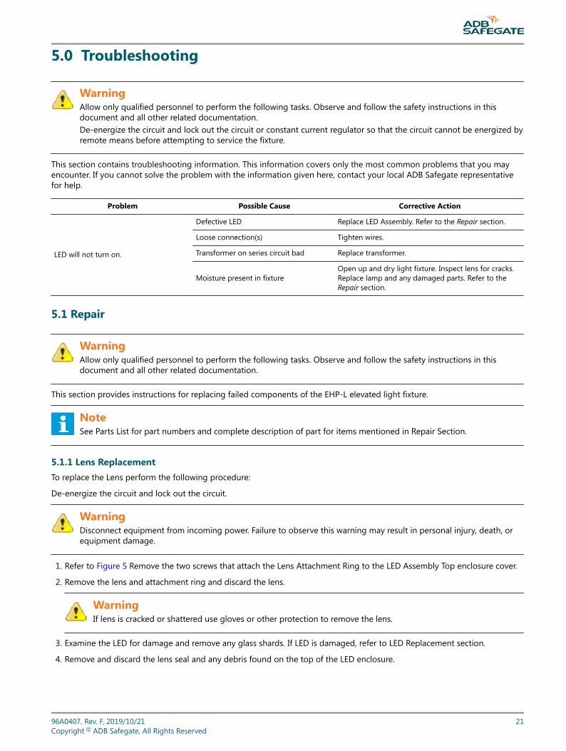
5.0 Troubleshooting
WarningAllow only qualified personnel to perform the following tasks. Observe and follow the safety instructions in thisdocument and all other related documentation.De-energize the circuit and lock out the circuit or constant current regulator so that the circuit cannot be energized byremote means before attempting to service the fixture.
This section contains troubleshooting information. This information covers only the most common problems that you mayencounter. If you cannot solve the problem with the information given here, contact your local ADB Safegate representativefor help.
Problem Possible Cause Corrective Action
LED will not turn on.
Defective LED Replace LED Assembly. Refer to the Repair section.
Loose connection(s) Tighten wires.
Transformer on series circuit bad Replace transformer.
Moisture present in fixtureOpen up and dry light fixture. Inspect lens for cracks.Replace lamp and any damaged parts. Refer to theRepair section.
5.1 Repair
WarningAllow only qualified personnel to perform the following tasks. Observe and follow the safety instructions in thisdocument and all other related documentation.
This section provides instructions for replacing failed components of the EHP-L elevated light fixture.
NoteSee Parts List for part numbers and complete description of part for items mentioned in Repair Section.
5.1.1 Lens ReplacementTo replace the Lens perform the following procedure:
De-energize the circuit and lock out the circuit.
WarningDisconnect equipment from incoming power. Failure to observe this warning may result in personal injury, death, orequipment damage.
1. Refer to Figure 5 Remove the two screws that attach the Lens Attachment Ring to the LED Assembly Top enclosure cover.
2. Remove the lens and attachment ring and discard the lens.
WarningIf lens is cracked or shattered use gloves or other protection to remove the lens.
3. Examine the LED for damage and remove any glass shards. If LED is damaged, refer to LED Replacement section.
4. Remove and discard the lens seal and any debris found on the top of the LED enclosure.
96A0407, Rev. F, 2019/10/21 21Copyright © ADB Safegate, All Rights Reserved

5. Install attachment ring over lens and place the new lens seal under the attachment ring and center it on the bottom of thelens.
6. Align the two screw holes in the attachment ring over the mating tapped holes in the top enclosure. Insert and tighten thescrews. Note: Alternate the tightening of the two screws to insure even loading on the lens to prevent cracking lensduring installation. Torque the screws to 19 in-lb.
Figure 5: Lens Attachment Ring
5.2 LED Assembly Replacement
To replace the LED assembly perform the following procedure:
1. De-energize the circuit and lock out the circuit.
WarningDisconnect equipment from incoming power. Failure to observe this warning may result in personal injury, death,or equipment damage.
2. Remove the Lens as described in the previous section and set the lens, attachment ring, lens seal, and screws/lockwashersaside.
3. Refer to Figure 6. Loosen the hex Allen set screws found under the LED enclosure assembly. Lift up on the LED enclosureand remove to gain access to the screws on the bottom enclosure cover. Note: The power lead attached to the LED PCB islong enough to completely remove the assembly from the J-Box.
Figure 6: Enclosure Set Screw Location
EHP-LTroubleshooting
22Copyright © ADB Safegate, All Rights Reserved

4. Refer to Figure 7 . Remove the 4 Philips pan head screws located in the corners of the bottom enclosure.
Figure 7: Bottom Enclosure Screws
5. Refer to Figure 6 through Figure 8. After the screws are removed, the Upper LED Assembly enclosure can be separatedfrom the rest of the assembly by locating and removing the LED lead disconnect from the PCB.
NoteSqueeze and pull upward on the latch located on the end of the Molex disconnect fitting to release and removethe LED leads from the PCB.
Figure 8: PCB LED Disconnect
6. After removing the LED disconnect, remove and discard the LED Assembly, which includes the LED Top cover enclosure,and replace with a new LED Assembly.
7. Reassemble the LED Assembly housing in reverse order of disassembly. Tighten all screws.
8. Reinstall the lens per instructions in Lens Replacement section.
9. Reinstall the assembly on the J-Box. Tighten all screws.
10. Return EHP-L Assembly to service.
5.2.1 LED PCB Assembly ReplacementTo replace the LED PCB perform the following procedure:
1. De-energize the circuit and lock out the circuit.
WarningDisconnect equipment from incoming power. Failure to observe this warning may result in personal injury, death,or equipment damage.
2. Refer Figure 9. Remove the LED Assembly enclosure and unlatch the LED power lead from the PCB as described in the LEDReplacement section.
96A0407, Rev. F, 2019/10/21 23Copyright © ADB Safegate, All Rights Reserved

3. Using a small electrical screwdriver, loosen the 3 screws in the PCB terminal block and remove the white, black and greenwires from the terminal block. Discard the removed PCB.
Figure 9: PCB Assembly Mounting Screws
4. Locate and remove the two Phillips pan head screws that secure the PCB to the bottom enclosure. Lift the PCB Assemblyout of the bottom enclosure.
5. Install the new PCB on the bottom enclosure using the screws and lockwashers taken out during the PCB removal.Reconnect the power leads to the terminal block in the same order as removed. Reattach the LED assembly wires thatwere disconnected from the PCB.
6. Reinstall the LED Assembly and tighten all screws.
7. Reinstall the assembly to the J-box and tighten all screws.
8. Return the EHP-L to service.
EHP-LTroubleshooting
24Copyright © ADB Safegate, All Rights Reserved

6.0 EHP Parts
Ordering Code LED Color G = Green1 Y = Yellow 1 B = Blue Power 1 = Voltage Driven, 95-264 VAC, 50/60 Hz1 2 = 50/60 Hz, Current Driven, 2.8-6.6 A Overall Height 1 = 8 inches with junction box, no coupling1 2 = 16 inches with junction box, 1.5-inch coupling1 3 = 24 inches with junction box, 1.5-inch coupling1 4 = 8 inches w/out j-box, with 1.5-inch coupling 5 = 8 inches w/out j-box, with 2-inch coupling 6 = 16 inches w/out j-box, with 1.5-inch coupling 7 = 24 inches w/out j-box, with 1.5-inch coupling 8 = 16 inches w/out j-box, with 2-inch coupling 9 = 24 inches w/out j-box, with 2-inch coupling A = 12 inch OAH w/out j-box, with 1.5-inch coupling B = 12 inch OAH w/out j-box, with 2-inch coupling Arctic Option 0 = Without arctic option 1 = With arctic option2 Notes 1 Not ETL Certified. 2 When powered by a parallel circuit, heater is designed for use at only 120
VAC, ±10%, 50/60 Hz.
EHP - X X X X 0
96A0407, Rev. F, 2019/10/21 25Copyright © ADB Safegate, All Rights Reserved

Figure 10: EHP-L Component Identification
6.1 Spare Components
Description Part No.
Enclosure bottom 62A2177
Enclosure gasket 63A1097
Frangible coupling, 1.5 inch, 12 TPI 62B0073/spare
Frangible reducer coupling, 2-1 inch, 11.5 TPI 61A0281/spare
Gasket, universal round 77A0216
Glassware, blue 63A1054-1
Glassware, green 63A1054-5
Glassware, yellow 63A1054-3
Junction box, round 77A0213
Junction box lid 62A2178
Junction box lid, round w/0.5-inch hub 77A0214
EHP-LEHP Parts
26Copyright © ADB Safegate, All Rights Reserved

Description Part No.
Lens attaching ring 60A2975-2
Seal, side-emitting LED lens 63A1048
PCB Assembly, LED AC PS, 400mA, W/O Bracket 44A6477-2-0400
PCB Assembly, LED PS 50/60HZ, W/ Bracket 44A7475-1
EHPL PCB INSULATOR PAPER 61A0441
96A0407, Rev. F, 2019/10/21 27Copyright © ADB Safegate, All Rights Reserved

Figure 11: EHP-L Assembly
EHP-LEHP Parts
28Copyright © ADB Safegate, All Rights Reserved

Figure 12: Assembly
96A0407, Rev. F, 2019/10/21 29Copyright © ADB Safegate, All Rights Reserved

Figure 13: Current Driven Enclosure
EHP-LEHP Parts
30Copyright © ADB Safegate, All Rights Reserved

Appendix A: SUPPORT
Our experienced engineers are available for support and service at all times, 24 hour/7 days a week. They are part of adynamic organization making sure the entire ADB SAFEGATE is committed to minimal disturbance for airport operations.
Table 6: ADB SAFEGATE SupportLive Technical Support - AmericasIf at any time you have a question or concern about your product, just contact ADB SAFEGATE’stechnical service department. Trained in all areas of system issues, troubleshooting, quality controland technical assistance, our highly experienced Technical support specialists are available 24 hoursa day, seven days a week to provide assistance over the phone.ADB SAFEGATE Americas Technical Service & Support (US & Canada): +1-800-545-4157ADB SAFEGATE Americas Technical Service & Support (International): +1-614-861-1304During regular business hours, you can also Chat with a Service Technician. We look forward toworking with you!Before You CallWhen you have an airfield lighting or system control system problem it is our goal to supportairfield maintenance staff as quickly as possible. To support this effort we ask that you have thefollowing information ready before calling.
• The airport code
• If not with an airport, then company name (prefer customer id number)
• Contact phone number and email address
• Product with part number preferable or product number
• Have you reviewed the product’s manual and troubleshooting guide
• Do you have a True RMS meter available (and any other necessary tools)
• Be located with the product ready to troubleshoot
NoteFor more information, see www.adbsafegate.com, or contact ADB SAFEGATE Support via email [email protected] orBrussels: +32 2 722 17 11Rest of Europe: +46 (0) 40 699 17 40Americas: +1 614 861 1304. Press 3 for technical service or press 4 for sales support.China: +86 (10) 8476 0106
A.1 ADB SAFEGATE website
The ADB SAFEGATE website, www.adbsafegate.com, offers information regarding our airport solutions, products, company,news, links, downloads, references, contacts and more.
96A0407, Rev. F, 2019/10/21 31Copyright © ADB Safegate, All Rights Reserved

A.2 Recycling
A.2.1 Local authority recyclingThe disposal of ADB SAFEGATE products is to be made at an applicable collection point for the recycling of electrical andelectronic equipment. The correct disposal of equipment prevents any potential negative consequences for the environmentand human health, which could otherwise be caused by inappropriate waste handling. The recycling of materials helps toconserve natural resources. For more detailed information about recycling of products, contact your local authority city office.
A.2.2 ADB SAFEGATE recyclingADB SAFEGATE is fully committed to environmentally-conscious manufacturing with strict monitoring of our own processes aswell as supplier components and sub-contractor operations. ADB SAFEGATE offers a recycling program for our products to allcustomers worldwide, whether or not the products were sold within the EU.
ADB SAFEGATE products and/or specific electrical and electronic component parts which are fully removed/separated fromany customer equipment and returned will be accepted for our recycling program.
All items returned must be clearly labelled as follows:
• For ROHS/WEEE Recycling
• Sender contact information (Name, Business Address, Phone number).
• Main Unit Serial Number.
ADB SAFEGATE will continue to monitor and update according for any future requirements for EU directives as and when EUmember states implement new regulations and or amendments. It is our aim to maintain our compliance plan and assist ourcustomers.
EHP-LSUPPORT
32Copyright © ADB Safegate, All Rights Reserved

96A0407, Rev. F, 2019/10/21 33Copyright © ADB Safegate, All Rights Reserved