Magic Cards: A New Augmented-Reality Approach
8
Magic Cards: A New Augmented- Reality Approach Olivier Demuynck and José Manuel Menéndez Augmented-reality applications commonly use markers for detecting and tracking virtual objects. However, these applications limit user interaction because they require knowledge of how to design and program 3D objects. The Magic Cards system offers an easier approach to creating and managing an unlimited number of virtual objects encoded on special markers. R endering effects and textures have become so realistic that people feel real emotions watching virtually created pictures or videos. Nevertheless, recreating virtual scenes and persons is neither easy nor fast, and it can be frustrating when someone wants to be the main actor in the virtual world. One option is to quickly design an avatar that characterizes someone by hair color, dressing style, and so on, and insert it in a virtual world. However, augmented-reality (AR) technology offers a better solution when the virtual content in ^^^_^^^_ a real environment decreases and a person can appear as his or her own image. Because human vi- sual perception is so important, the AR illusion of a virtual object in your own hands is compelling for many people. This has led to AR applications in such areas as phobia therapy. 1 AR most often requires two computer vision techniques: de- tection and tracking. In some cases, detection implies the ex- tended use of computer vision and image-processing techniques for human body, hand, or face detec- tion. On the other hand, AR can be much simpler when oriented on marker and pattern detection and tracking. 2,3 In addition, numerous libraries exist from which devel- opers can implement pattern-based AR applications. 4 For example, they can use QR (quick response) codes to encode more data on the markers. 5 Figure 1 pre- sents some example markers for AR applications. In some applications, scene or object detection aims for morphological distortion, transformation, and so on. Nevertheless, in most cases, AR consists of representing a 3D virtual model that was previ- ously recorded by a computer or camera-equipped device, such as a mobile phone. 6,7 To enable such 3D object representation, we've developed Magic Cards, a marker-based application that lets us- ers create a virtual object in a few simple steps. The object doesn't require a 3D model previously stored in memory, and the marker (magic card) we use also encodes shape and color information. Magic-Card Design We wanted to give users an easy way to create an unlimited number of virtual objects, which we achieve through a unique decoding algorithm. The kinds of objects users can create are lim- ited to simple designs that can respond to a basic rule. Specifically, the objects must present a rota- tion axis that's given by the normal line from the magic card's center. This lets users design a magic card by drawing just the half-shape and indicating the color information. They can also fix some size proportions and, optionally, apply labels to cover a virtual object with a texture other than color. The axial-symmetry requirement reduces an ob- ject's perspective and orientation deformations to elliptical form, which lets us use a circular marker for simple, robust detection. Unlike typical AR appli- cations, we don't use a projective camera model. We simply render the object following its parallel projec- tion into a scene, by scaling the detected elliptical form from the virtual object's base to its top. Input Bitmap Files Figure 2 presents a set of bitmap format files for creating three magic cards. The two files for each object are actually redundant because the color information also presents the shape information. However, we present both files to help users inter-
Transcript of Magic Cards: A New Augmented-Reality Approach

Magic Cards: A New Augmented-Reality Approach Olivier Demuynck and José Manuel Menéndez
Augmented-reality applications commonly use markers for detecting and tracking virtual objects. However, these applications limit user interaction because they require knowledge of how to design and program 3D objects. The Magic Cards system offers an easier approach to creating and managing an unlimited number of virtual objects encoded on special markers.
R endering effects and textures have become so realistic that people feel real emotions watching virtually created pictures or videos.
Nevertheless, recreating virtual scenes and persons is neither easy nor fast, and it can be frustrating when someone wants to be the main actor in the virtual world. One option is to quickly design an avatar that characterizes someone by hair color, dressing style, and so on, and insert it in a virtual world. However, augmented-reality (AR) technology offers a better solution when the virtual content in ^ ^ ^ _ ^ ^ ^ _ a real environment decreases and
a person can appear as his or her own image. Because human visual perception is so important, the AR illusion of a virtual object in your own hands is compelling for many people. This has led to AR applications in such areas as phobia therapy.1
AR most often requires two computer vision techniques: detection and tracking. In some cases, detection implies the extended use of computer vision and image-processing techniques for human body, hand, or face detection. On the other hand, AR can be much simpler when oriented
on marker and pattern detection and tracking.2,3 In addition, numerous libraries exist from which developers can implement pattern-based AR applications.4
For example, they can use QR (quick response) codes to encode more data on the markers.5 Figure 1 presents some example markers for AR applications.
In some applications, scene or object detection aims for morphological distortion, transformation, and so on. Nevertheless, in most cases, AR consists
of representing a 3D virtual model that was previously recorded by a computer or camera-equipped device, such as a mobile phone.6,7 To enable such 3D object representation, we've developed Magic Cards, a marker-based application that lets users create a virtual object in a few simple steps. The object doesn't require a 3D model previously stored in memory, and the marker (magic card) we use also encodes shape and color information.
Magic-Card Design We wanted to give users an easy way to create an unlimited number of virtual objects, which we achieve through a unique decoding algorithm. The kinds of objects users can create are limited to simple designs that can respond to a basic rule. Specifically, the objects must present a rotation axis that's given by the normal line from the magic card's center. This lets users design a magic card by drawing just the half-shape and indicating the color information. They can also fix some size proportions and, optionally, apply labels to cover a virtual object with a texture other than color.
The axial-symmetry requirement reduces an object's perspective and orientation deformations to elliptical form, which lets us use a circular marker for simple, robust detection. Unlike typical AR applications, we don't use a projective camera model. We simply render the object following its parallel projection into a scene, by scaling the detected elliptical form from the virtual object's base to its top.
Input Bitmap Files
Figure 2 presents a set of bitmap format files for creating three magic cards. The two files for each object are actually redundant because the color information also presents the shape information. However, we present both files to help users inter-

(a) (b)
(c) (d)
Figure 1. Some markers for augmented-reality (AR)
applications: (a) an ARToolKit-type marker,4 (b) the
Eiffel Tower,6 (c) a wine glass,7 and (d) a beer bottle.7
Such markers can simplify the creation of AR
applications, compared to using computer vision or
image-processing techniques.
ested in creating a white virtual object, which still needs shape information.
From the binary shape, we extract a grayscale information vector in the usual [0 255] range for image coding, which is a technique used for rendering 2.5D images. The white information corresponds to the maximum distance from the rotation axis; the black information corresponds to the minimum distance from this axis. We process those distances in pixels for a given column of the binary shape. Intermediate grayscale values are processed proportionally to those extreme points of the shape. For the color in the area given by the shape mask, we compute the mean color value for each column from left to right. As Figure 2 shows, we spread some color points over the virtual object to keep the rendering from looking too uniform. (We discuss shape- and color-encoded information on the resulting magic card later.)
Virtual-Object Proportions To allow some size variation for each created object, we set the maximum height and width. Depending on the magic-card's size detected in the scene, we apply those scales to render the virtual object.
To encode these parameters on the magic card, we first use the green-on-blue ratio to determine the object's height scale:
Heightcoiori x MaxHdghtScaie = objectHeightScale. Hdghtcolor2
(0
Figure 2. Bitmap files for creating magic cards: (a) a
wine glass, (b) a bottle of wine, and (c) an hourglass.
The two files for each object are redundant but help
distinguish the shape of a white object.
We then use the red-on-green ratio to determine the object's maximum radius scale:
Hd8htcolorl x MaxRadiusScale = Heigntco\ox2
Object(Min/Max)RadiusScale.
For our experiments, we set MaxHeightScale at 4 and MaxRadiusScale at 3. Those values, given the distance range of magic-card detection, helped keep the virtual objects from appearing too large.
We encode those values in the following order: ObjectHeightScale, ObjectMaxRadiusScale, and Ob-jectMinRadiusScale. This ensures that green, blue, and red alternate to further ease magic-card decoding. Regarding the virtual objects in Figure 2, this step is fundamental to maintain each object's relative dimensions when the objects appear together. That is, the bottle is taller than the glass, and the hourglass is thinner and smaller than the other objects.
The Labeling Option The Magic Cards application lets users associate

• i r< < >]> . i
(a) (b)
Figure 3. A magic card: (a) front and (b) profile. We chose a circular
marker partly because circular projection is an easily detectable elliptical
form that supports a robust marker-detection algorithm.
Proportion encoded information Shape encoded information Color encoded information
Proportion encoded information and texturing information (ID = 1) Shape encoded information Color encoded information
Proportion encoded information Shape encoded information Color encoded information
Figure 4. Shape, color, and scale information wrapped around the magic
card, for the (a) wine glass, (b) wine bottle, and (c) hourglass in Figure 2.
A black gap indicates the starting point for future decoding.
an image with a virtual object to fully or partly texturize it. For example, for a virtual bottle, users could add a label beyond what the decoding algorithm could generate.
The user must position the image's starting and ending points over the virtual object and identify it with a binary code. We later show how we used two-bit image IDs to manage up to four different images.
The Magic Cards application completes the scale information by using two white markers that refer to the starting and ending points. It then inserts a binary code of red and blue colors, associated with the binary values 0 and 1, respectively, between two same-sized white markers.
The Magic Card
Figure 3 presents two views of a magic card. In Figure 3b, the distances x\, x2, and x3 (expressed in pixels) and centered points A, B, and C define the desired geometry for magic-card detection. Because virtual objects have axial symmetry, they don't need to be oriented respective to the rotation axis. Also, circular projection is an easily detectable elliptical form and supports a robust detection algorithm. Indeed, depending on the magic card's orientation, the Magic Cards application can use the observed ellipse to render the virtual object in its current orientation.
Referring to Figure 3b, we use the following proportionality and centering rules to ensure robust magic-card detection:
3ei e[-/3,/3],Xi =x3 + ei
3£2 e [-7,7], dist (A, C) x a = xi + ei
3e3e[-<5,<5], dist(A,B) = dist(B,C) + e3 (1)
Except for the floating value a, which fixes the geometric proportionality, all the values in Equation 1 are integers expressed in pixels. The ranges for e¡ (i e [1, 3]) are defined as macro constant data in the Magic Cards application.
The Results of Magic-Card Generation
Once the Magic Card application processes the shape, color, and scale information, it wraps that information around the designed magic card, including any labeling. As Figure 4 shows, the shape and color information both complete the 2it radians in the same rotational direction and indicate angularly a unique point of the virtual object. A black gap indicates the starting point for future decoding.
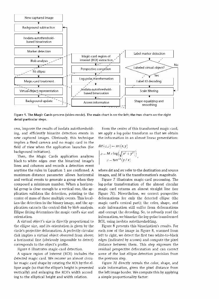
The Magic Cards Application Figure 5 describes the global process. The main chart is on the left; the two charts on the right detail particular steps. We focus here on detecting and treating magic cards and representing the virtual objects. Nevertheless, we cover some well-known computer vision techniques.
We employ background subtraction only for video mode. We use it to lightly speed up the pro-
New captured ¡mage
Background subtraction
Isodata-autothreshold-based binarization
Marker detection
Blob analysis , ' '
_ , - ' Fit ellipse
Magic-card treatment
Virtual-dbject representation
Background update
Magic-card region of interest (ROI) extraction,'
~TT^
Perspective correction
~3ZL Log-polar, transformation
Jsodata-autothreshold-based binarization
^ ~ Access information Shape equalizing and
smoothing
Figure 5. The Magic Cards process (video mode). The main chart is on the left; the two charts on the right
detail particular steps.
cess, improve the results of isodata autothreshold-ing, and efficiently binarize detection events in new captured images. Obviously, this technique implies a fixed camera and no magic card in the field of view when the application launches (for background initiation).
Then, the Magic Cards application analyzes black-to-white edges over the binarized image's lines and columns and records a detection event anytime the rules in Equation 1 are confirmed. A maximum-distance parameter allows horizontal and vertical events to generate a group when they composed a minimum number. When a horizontal group is close enough to a vertical one, the application validates the detection, pointing to the center of mass of those multiple events. This localizes the detection in the binary image, and the application extracts the central disk by blob analysis. Ellipse fitting determines the magic card's size and orientation.
A virtual object's size is directly proportional to the ellipse size, and its orientation is given by the circle's projective deformation. A perfectly circular disk implies a virtual object observed from above; a horizontal line (obviously impossible to detect) corresponds to the object's profile.
Figure 6 illustrates magic-card detection. A square region of interest (ROI) includes the
detected magic card. We recover an almost circular magic-card shape by rotating the ROI by the ellipse angle (so that the ellipse's height is presented vertically) and enlarging the ROI's width according to the elliptical height and width relation.
From the center of this transformed magic card, we apply a log-polar transform so that we obtain the information in an almost linear presentation:
dst(jfi,p)<— src(x,y)
p = Mx\og([yJ(x2+y2
'.p = tan -1 (y / x)
where dst and src refer to the destination and source images, and M is the transformation's magnitude.
Figure 7 illustrates magic-card processing. The log-polar transformation of the almost circular magic card returns an almost straight line (see Figure 7d). Nevertheless, we correct perspective deformations for only the detected ellipse (the magic card's central part); the color, shape, and scale information still suffer from deformations and corrupt the decoding. So, to robustly read the information, we binarize the log-polar transformed ROI, using isodata autothresholding.
Figure 8 presents this binarization's results. For each row of the image in Figure 8, scanned from left to right, we detect the first two white-to-black edges (indicated by arrows) and compute the pixel distance between them. This step expresses the residual perspective deformation and can correct some of the lost ellipse-detection precision from the previous step.
Figure 7d directly reveals the color, shape, and scale information, given the pixel distance from the left image border. We compute this by applying a simple proportionality factor:

Figure 6. Magic-card detection, (a) The original image, (b) The magic cards detected in the isodata-
autothresholding-based binarized image.
Color[i] = WBi [i] + (WB2 [i] - WBi [i]) x (i
Shape [i] = WBi [i] + (WB2 [i] - WBi [i]) x 7
Scale [i] = WBi [i] + (WB2 [i] - WBi [i]) x <S,
where W£>i[i] and WB2[i] are integer values and refer respectively to the first and second white-to-black edge position, in the raw image i. The floating values ¡3, 7, and «5 are the proportionality factors for color, shape, and scale information, respectively. Shape[i] records just one value in the range [0 255]; Color[i] and Sca!e[i] record the red, green, and blue channels.
The Magic Cards application uses the grayscale image, obtained by converting the color scale information bar, to determine whether to label the virtual object. Once again, it applies isodata auto-thresholding on this image. If it finds just four white stripes and their size variance is low enough, it labels the object. In this case, it decodes the label and accesses the associated image.
The application denoises the scale bar mainly by forcing the value to be red, green, or blue as it is on the original magic card. It chooses the maximum value among those three color channels. Nevertheless, color-printing fidelity and camera wavelength response can sometimes cause errors (mainly between the green and blue channels). So, additional filtering assumes the color order and proportions for information coding. The first
half codes the ObjectHeightScale information, the third quarter codes ObjectMinRadiusScale, and the fourth quarter codes ObjectMaxRadiusScale.
Finally, by slightly smoothing the shape information, the application reduces possible imaging-sensor noise before equalization.
To further render the virtual objects, the application uses information from the detected ellipse. The fact that the rendering follows the parallel projection affects the perspective rendering mainly when virtual objects are observed in a close-up. This isn't the case here, taking into account the objects' size and the distance between them and the camera. So, from the detected ellipse's center (the virtual object's base) to the object's height, the application successively draws scaled and colored ellipses according to the decoded information. The center of an ellipse to draw is given it-eratively by these formulas:
X — Xdetected + COS (Angkdet ected
xObjectHeight[i\
Wldthdetected X COS
[ heightdetected
Y = Ydetected - Sin (Ailgkdetected ) <ObjectHeight [i]
Widthdetecti
heightdetected

where Angle¿etecte¿ is the detected ellipse's angle. ObjectHeight[i] is the virtual object's height at step i, starting from the virtual object's base to its maximum height, proportional to the ellipse size and processed with the decoded parameter ObjectHeightScale. The width¿etecte¿ and heightdetected parameters are the detected ellipse's width and height.
We compute each new ellipse's size:
Width = WidtZldetected
x (ObjectMinRadiusScale
+ (Scale[i}/255)
x (ObjectMaxRadiusScale
-ObjectMinRadiusScale))
height = ZldgZltdetected
x (ObjectMinRadiusScale
+ (Scale[i}/255)
x (ObjectMaxRadiusScale
-ObjectMinRadiusScale)),
where ScaZe[i] points to the corresponding decoded value (in the range [0, 255]) at a given virtual-object height.
Obviously, the ellipse angle remains the same for all drawn ellipses.
Figure 9 presents the results for rendering a virtual wine bottle and wine glass. Figures 4a and 4b show these two objects' markers. (The wine bottle's label ID referenced the E.T.S. Ingenieros de Telecomunicación logo.)
Figure 10 demonstrates the application's effectiveness in different lighting conditions. Figure 10a shows a scene with indoor lighting; Figure 10 shows the same scene with a virtual object rendering the Berlin TV tower. Figure 10c shows an outdoor scene on a sunny day; Figure lOd shows the same scene with the virtual hourglass (Figure 4c shows the corresponding magic card).
Detection Limits In the three cases in Figures 9 and 10, the magic cards appeared at different orientations and distances. We tested the Magic Cards application to determine the minimum size and maximum angle for the magic card to ensure detection and proper decoding. To do so, as we used the application, we recorded the detected magic card ellipse information in a file for further analysis.
To test the minimum size, we placed the magic card at varying distances from a webcam in a fairly planar position. Using the ellipse area formula
Figure 7. Magic-card processing, (a) An image of the ROI. (b) The ellipse-
angle-rotated ROI. (c) The ROI distorted by the ellipse height-to-width
relation, (d) The log-polar transformed ROI. These processes help
straighten the shape, color, and scale information to ease the decoding.
Figure 8. Binarization of the magic card. For each row of the image,
scanned from left to right, we detect the first two white-to-black edges
(indicated by arrows) and compute the pixel distance between them.
This step expresses the residual perspective deformation and can correct
some of the lost ellipse-detection precision from the previous step.
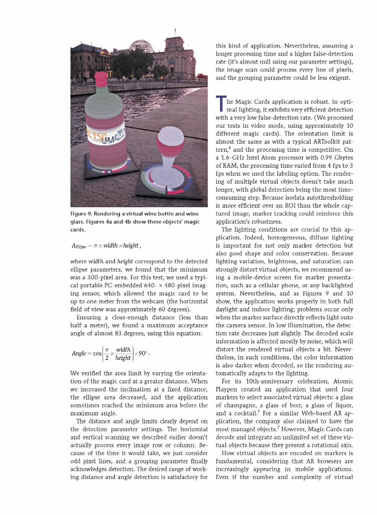
Figure 9. Rendering a virtual wine bottle and wine
glass. Figures 4a and 4b show these objects' magic
cards.
Amipse = 7T x width x height,
where width and height correspond to the detected ellipse parameters, we found that the minimum was a 300-pixel area. For this test, we used a typical portable PC-embedded 640- x 480-pixel imaging sensor, which allowed the magic card to be up to one meter from the webcam (the horizontal field of view was approximately 60 degrees).
Ensuring a close-enough distance (less than half a meter), we found a maximum acceptance angle of almost 83 degrees, using this equation:
Angle - cos 7T width — X
2 height x90°
We verified the area limit by varying the orientation of the magic card at a greater distance. When we increased the inclination at a fixed distance, the ellipse area decreased, and the application sometimes reached the minimum area before the maximum angle.
The distance and angle limits clearly depend on the detection parameter settings. The horizontal and vertical scanning we described earlier doesn't actually process every image row or column. Because of the time it would take, we just consider odd pixel lines, and a grouping parameter finally acknowledges detection. The desired range of working distance and angle detection is satisfactory for
this kind of application. Nevertheless, assuming a longer processing time and a higher false-detection rate (it's almost null using our parameter settings), the image scan could process every line of pixels, and the grouping parameter could be less exigent.
The Magic Cards application is robust. In optimal lighting, it exhibits very efficient detection
with a very low false-detection rate. (We processed our tests in video mode, using approximately 10 different magic cards). The orientation limit is almost the same as with a typical ARToolkit pattern,4 and the processing time is competitive. On a 1.6-GHz Intel Atom processor with 0.99 Gbytes of RAM, the processing time varied from 4 fps to 3 fps when we used the labeling option. The rendering of multiple virtual objects doesn't take much longer, with global detection being the most time-consuming step. Because isodata autothresholding is more efficient over an ROI than the whole captured image, marker tracking could reinforce this application's robustness.
The lighting conditions are crucial to this application. Indeed, homogeneous, diffuse lighting is important for not only marker detection but also good shape and color conservation. Because lighting variation, brightness, and saturation can strongly distort virtual objects, we recommend using a mobile-device screen for marker presentation, such as a cellular phone, or any backlighted system. Nevertheless, and as Figures 9 and 10 show, the application works properly in both full daylight and indoor lighting; problems occur only when the marker surface directly reflects light onto the camera sensor. In low illumination, the detection rate decreases just slightly. The decoded scale information is affected mostly by noise, which will distort the rendered virtual objects a bit. Nevertheless, in such conditions, the color information is also darker when decoded, so the rendering automatically adapts to the lighting.
For its 10th-anniversary celebration, Atomic Playpen created an application that used four markers to select associated virtual objects: a glass of champagne, a glass of beer, a glass of liquor, and a cocktail.7 For a similar Web-based AR application, the company also claimed to have the most managed objects.7 However, Magic Cards can decode and integrate an unlimited set of these virtual objects because they present a rotational axis.
How virtual objects are encoded on markers is fundamental, considering that AR browsers are increasingly appearing in mobile applications. Even if the number and complexity of virtual

objects are restricted, applications such as ours can help reduce bandwidth because the models don't need to be transferred from servers to clients. They can be directly computed using the markers on the clients.
The labeling option might appear to contradict the global flexibility we claim for Magic Cards. This option could be considered a way to associate color with a virtual object without encoding it on the marker. So, each object would require its own recorded image, and the application wouldn't be generic anymore. So, for this option to be practical, the label ID coding should use some 2D bar code method to code and manage a huge number of images. Even considering bar codes' robustness (validated by a redundancy method), our application might have difficulty reading them. Nevertheless, and because we propose only 2-bit-ID image coding, the basic idea is currently just to manage a logo or brand, not texturize the virtual object. This option actually reinforces our original proposal of giving users an easy way to design virtual objects, because a simple additional step lets them create a more complex object. v "
References
1. M.C. Juan et al., "An Augmented Reality System for Treating Psychological Disorders: Application to Phobia to Cockroaches," Proc. 3rd IEEE/ACM Int'l Symp. Mixed and Augmented Reality (ISMAR 04), IEEE CS, 2004, pp. 256-257.
2. X. Zhang, S. Fronz, and N. Navab, "Visual Marker Detection and Decoding in AR Systems: A Comparative Study," Proc. IEEE Int'l Symp. Mixed and Augmented Reality (ISMAR 02), IEEE, 2002, pp. 97-106.
3. M. Fiala, "ARTag, a Fiducial Marker System Using Digital Techniques," Proc. IEEE Computer Society Conf. Computer Vision and Pattern Recognition (CVPR 05), vol. 2, IEEE, 2005, pp. 590-596.
4."ARToolKit," 2012; www.hitl.washington.edu/artoolkit. 5. T-W. Kan, C-H. Teng, and W-S. Chou, "Applying
QR Code in Augmented Reality Applications," Proc. 8th Int'l Conf. Virtual Reality Continuum and Its Applications in Industry (VRCAI 09), ACM, 2009, pp. 253-257.
6. M. Muñera, "Augmented Reality," blog, 26 Oct. 2010; www.mauriciomunera.com/?cat=5.
7. "Cheers to 10 Years!," Atomic Playpen, 2010; www. atomicplaypen.com/work_ap_cheerstolOyears.aspx.
Figure 10. Magic-card results in different lighting conditions, (a) A scene
with indoor lighting, (b) The same scene with a virtual object rendering
the Berlin TV tower, (c) An outdoor scene on a sunny day. (d) The same
scene with the virtual hourglass. The marker renders virtual objects
properly in any uniformly lit scene.