MAG & VLF SUR - Ontario
23
52P09SW9449 2.18748 FROND LAKE 010 RECEIVED JAN l 9 1988 MINING LANDS SECTION REPORT . ON GROUND MAOETIC AND VLF-ELECTROMAGNETIC SURVEYS MIMINISKA LAKE AREA, ONTARIO FOR GOLD FIELDS CANADIAN MINING, L.D. OCTOBER, 1987 URQUHART DVORAK LIMITED
Transcript of MAG & VLF SUR - Ontario

52P09SW9449 2.18748 FROND LAKE 010
RECEIVEDJAN l 9 1988
MINING LANDS SECTION
REPORT .
ON
GROUND MAOETIC AND VLF-ELECTROMAGNETIC
SURVEYS
MIMINISKA LAKE AREA, ONTARIO
FOR
GOLD FIELDS CANADIAN MINING, L.D.
OCTOBER, 1987
URQUHART DVORAK LIMITED

1.0 GENERAL INFORMATION
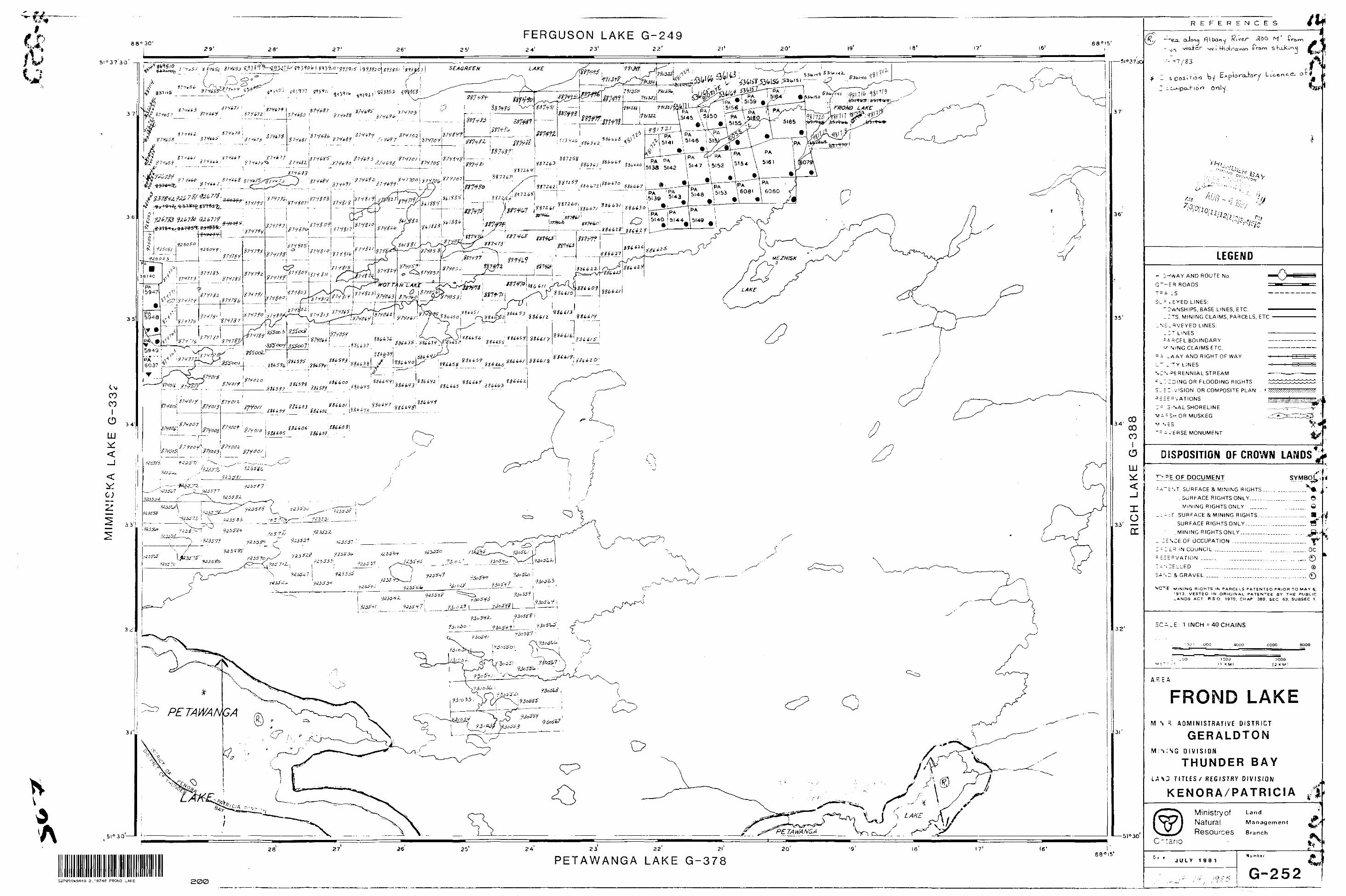
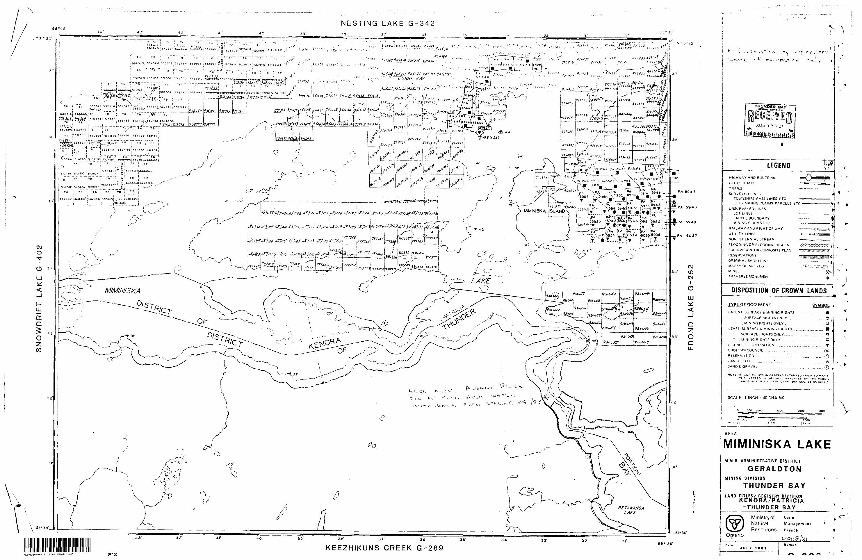
1.1 Location, Access and InfrastructureThe property is located in the Miminiska Lake area, which in turn is located approximately 115 km east of the town of Pickle Lake, northwestern Ontario. It is accessible by air only.
The nearest townsite facilities exist at Pickle Lake where skilled and semi-skilled workers are in poor to fair supply.
1.2 Survey Grids and Claims CoveredThe northern grid, BLA, was established with the base line at anazimuth of NIBBLE and the grid lines at N0750 E. It covers claims940653, 940654, 926785, and portions of claims 940655, 874657, and874658.
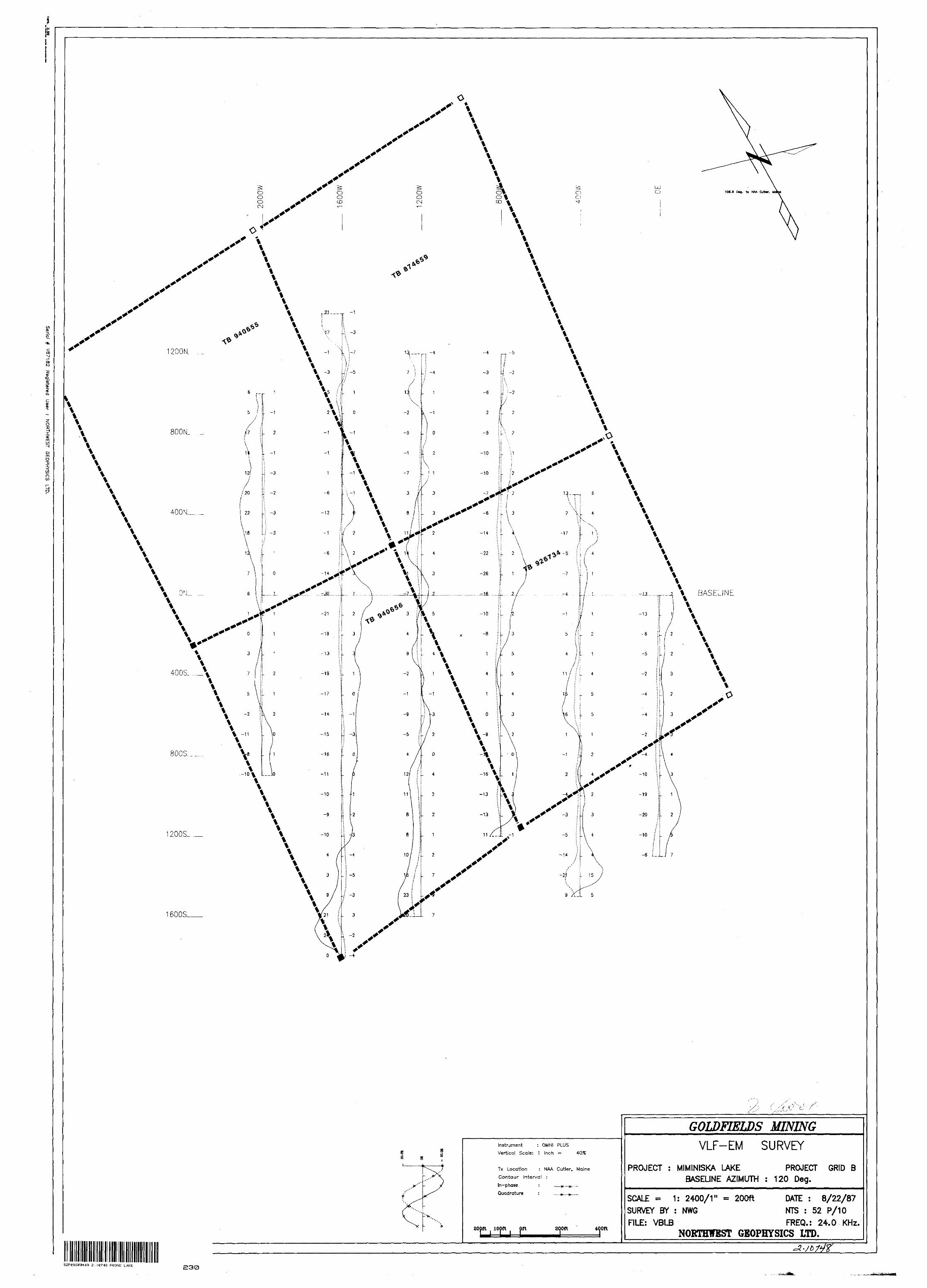
The southern grid, ELB, was established with the base line at an azimuth of N120C'E and the grid lines at N0300 E. It covers claim 940656 and portions of claims 940655, 874659, and 926784.
1.3 Geophysical Surveying and Instrumentation Approximately 6.22 line-km (3.86 miles) of ground magnetic and VLF-electromagnetic surveys were carried out on grid BLA, and approximately 4.14 line-km (2.58 miles) on grid BLB. The surveys were carried out in the fall of 1987 by Northwest Geophysics Limited of Thunder Bay, Ontario. Both the magnetic and VLF-EM data were acquired using an EDA Omni Plus system. The VLF-EM receiver was tuned to NAA, Cutler, Maine, transmitter which occurs at an azimuth of N106.9C'E. The magnetic data was presented in the form of posted value maps, the VLF-EM data as stacked profile maps. The digital magnetic data base was generated by Urquhart Dvorak Limited of Toronto, Ontario, and contour maps were produced, which in turn served as the basis for interpretation purposes.
2.0 INTERPRETATION
2.1 Total Magnetic Field SurveysThe magnetic data was collected on lines spaced at 400 ft., with stations established at 100 ft. intervals. Results of the magnetic surveys are presented as contour maps at a scale of 1:2,400 (l" * 200 ft.), one map per grid.
2.1.1 Grid BLAThe total magnetic field varies over an extremely broad range of values, from approximately -20 nT to 35,500 nT, above background. The total magnetic field is dominated by a northwest-southesterly striking anomaly extending from 200E on line 00 toward station 900E
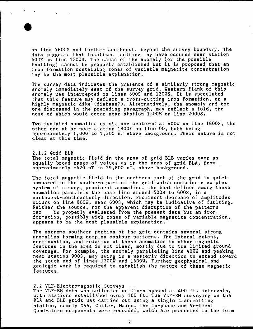
on line 1600S and further southeast, beyond the survey boundary. The data suggests that localized faulting may have occured near station 600E on line 1200S. The cause of the anomaly (or the possible faulting) cannot be properly established but it is proposed that an iron formation containing zones of variable magnetite concentration may be the most plausible explanation.
The survey data indicates the presence of a similarly strong magnetic anomaly immediately east of the survey grid. Western flank of this anomaly was intercepted on lines 800S and 1200S. It is speculated that this feature may reflect a cross-cutting iron formation, or a highly magnetic dike (diabase?). Alternatively, the anomaly and the one discussed in the preceding paragraph, may reflect a fold, the nose of which would occur near station 1500E on line 2000S.
Two isolated anomalies exist, one centered at 400W on line 1600S, the other one at or near station 1800E on line 00, both being approximately 1,000 to 1,300 nT above background. Their nature is not clear at this time.
2.1.2 Grid BLBThe total magnetic field in the area of grid BLB varies over an equally broad range of values as in the area of grid BLA, from approximately -620 nT to 29,800 nT, above background.
The total magnetic field in the northern part of the grid is quiet compared to the southern part of the grid which contains a complex system of strong, prominent anomalies. The best defined among these anomalies parallels the base line around 500S to 600S, in a northwest-southeasterly direction. Prominent decrease of amplitudes occurs on line 800W, near 600S, which may be indicative of faulting. Neither the source, nor the apparent disruption of the patterns can be properly evaluated from the present data but an iron formation, possibly with zones of variable magnetite concentration, appears to be the most plausible explanation.
The extreme southern portion of the grid contains several strong anomalies forming complex contour patterns. The lateral extent, continuation, and relation of these anomalies to other magnetic features in the area is not clear, mostly due to the limited ground coverage. For example, the anomaly paralleling line AOOW and peaking near station 900S, may swing in a westerly direction to extend toward the south end of lines 1200W and 1600W. Further geophysical and geologic work is required to establish the nature of these magnetic features.
2.2 VLF-Electromagnetic SurveysThe VLF-EM data was collected on lines spaced at 400 ft. intervals, with stations established every 100 ft. The VLF-EM surveying on the BLA and BLB grids was carried out using a single transmitting station, namely NAA, Cutler, Maine. The In-phase and Vertical Quadrature components were recorded, which are presented in the form
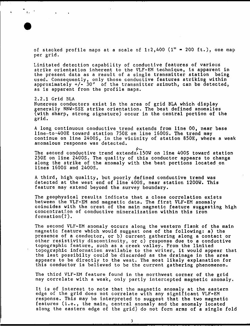
of stacked profile maps at a scale of 1:2,400 (l" - 200 ft.)* one map per grid.
Limitated detection capability of conductive features of various strike orientation inherent to the VLF-EM technique, is apparent in the present data as a result of a single transmitter station being used. Consequently, only those conductive features striking within approximately +/- 3Q 0 of the transmitter azimuth, can be detected, as is apparent from the profile maps.
2.2.1 Grid BLANumerous conductors exist in the area of grid BLA which displaygenerally NNW-SSE strike orientation. The best defined anomalies(with sharp, strong signature) occur in the central portion of thegrid.
A long continuous conductive trend extends from line 00, near base line~to-400E toward station 750E on line 1600S. The trend may continue on line 2400S, in the vicinity of station 850E, where a weak anomalous response was detected.
frt*The second conductive trend extends*150W on line 400S toward station 250E on line 2400S. The quality of this conductor appears to change along the strike of the anomaly with the best portions located on lines 1600S and 2400S.
A third, high quality, but poorly defined conductive trend was detected at the west end of line 400S, near station 1200W. This feature may extend beyond the survey boundary.
The geophysical results indicate that a close correlation exists between the VLF-EM and magnetic data. The first VLF-EM anomaly coincides with the crest of the main magnetic feature suggesting high concentration of conductive mineralization within this iron formation(?).
The second VLF-EM anomaly occurs along the western flank of the main magnetic feature which would suggest one of the following: a) the presence of a conductor, or b) current gathering along a contact or other resistivity discontinuity, or c) response due to a conductive topographic feature, such as a creek valley. From the limited topographic information available to the writer, it would appear that the last possibilty could be discarded as the drainage in the area appears to be directly to the west. The most likely explanation for this conductor is believed to be the current gathering phenomenon.
The third VLF-EM feature found in the northwest corner of the grid may correlate with a weak, only partly intercepted magnetic anomaly.
It is of interest to note that the magnetic anomaly at the eastern edge of the grid does not correlate with any significant VLF-EM response. This may be interpreted to suggest that the two magnetic features (i.e., the main, central anomaly and the anomaly located along the eastern edge of the grid) do not form arms of a single fold

as suggested earlier.
2.2.2 Grid BLBThe southern grid, BLB, contains several conductors and conductive zones, all of generally westerly orientation. The north portion of the grid contains a semi continuous (?) trend extending from station 1250N on line 1600W toward station 750N on line 800W, and possibly further southeast. This trend is believed to constitute a continuation of a similar conductive trend from grid BLA, paralleling the main magnetic anomaly from the west.
The central portion of the grid contains a narrow, well defined anomaly extending from the north end of line 400W toward station 250N on line 2000W. This anomaly may follow a topographic feature, such as a valley, which at the west grid boundary connects to a small creek. Consequently, this VLF-EM anomaly may be merely indicative of conductive valley sediments.
The south portion of the grid is dominated by a broad conductive feature extending in an arcuate manner from station 550S on line 2000W toward station 950S on line 00. At this location, the zone appears to swing in a westerly direction toward station 1250S on line 400W, and possibly further west toward the south end of line 1600W.
At places, the VLF-EM data shows good correlation with the total magnetic field data. This is particularly true in the south part of the grid where the VLF-EM anomalies correlate closely with the main magnetic anomaly crossing the grid parallel to the base line. A degree of correlation is also suggested for the magnetic anomaly paralleling line 400W and its possible extension to the south end of line 1600W. Such a correlation suggests the presence of conductive mineralization in association with the magnetic (iron formation?) anomaly.
The central VLF-EM conductor approximates the regional (?) trough of the magnetic field in the area of grid BLB. However, because of the lack of a distinctive magnetic signature and because of the location of the VLF-EM anomaly along a creek valley, it is believed that this conductive feature is of little exploration consequence. Similarly, the northern conductive trend is not regarded as a priority target for reasons stated earlier.
3.0 CONCLUSIONS AND RECOMMENDATIONS
Combined ground total field magnetic and VLF-EM surveys totalling 10.33 km (6.44 miles) were carried out over grids BLA and BLB located in the Miminiska Lake area of northwest Ontario in the fall of 1987. The magnetic data indicates the presence of several distinct, well defined anomalies which may constitute portions of local or regional folds(7). Large magnetic amplitudes suggest the source of these anomalies to be iron formations.

The VLF-EM data indicates the presence of conductive material (mineralization?) in association with these magnetic anomalies which makes them priority targets. Other VLF-EM anomalies encountered in the area of the two grids appear to be of low exploration interest as they may be merely indicative of topographic features and/or current gathering.
It is recommended that in order to fully investigate the lateral extent, nature, and exploration significance of the individual geophysical anomalies, ground coverage be extended and further geophysical and geologic work be carried out.
Respectfully submitted, Urquhart Dvorak Limited
Zbynek Dvorak Consulting Geophysicist

STATEMENT OF QUALIFICATIONS
I, Zbynek Dvorak, of the city of North York, Province of Ontario, do hereby certify that:
1. I am a geophysicist residing at 146 Three Valleys Drive, Don Mills, Ontario;
2. I am a graduate of Charles University, Prague, Czechoslovakia, with a Graduate Degree (M. Se.) (1961) in Geophysics, and of the Czechoslovak Academy of Sciences with a C. Se. (Ph.D.) degree (1967) in Geophysics;
3. I have been practising my profession since July 1961;
4. I have been employed by Urquhart Dvorak Limited since October, 1984, as a consulting geophysicist;
5. The statements made by me in this report represent my best opinion and judgment.
j..\0 ^ci October, 1987
Zbynek Dvorak
Toronto, Ontario ' j..\0'

MIMINISKA LAKE

MIMINISKA LAKE
^25075
^f*
GOLDFIELDS CANADIAN MINING LTD
LOCATION OF GRID A AND GRID B
MAGNETOMETER AND VLF SURVEYS
SCALE 1 inch - 1/4 mile871/21*

STATEMENT OF QUALIFICATIONS
I, Zbynek Dvorak, of the city of North York, Province of Ontario, do hereby certify that:
1. I am a geophysicist residing at 146 Three Valleys Drive, Don Mills, Ontario;
2. I am a graduate of Charles University, Prague, Czechoslovakia, with a Graduate Degree (M.Se.) (1961) in Geophysics, and of the Czechoslovak Academy of Sciences with a C.Se. (Ph.D.) degree (1967) in Geophysics;
3. I have been practising my profession since July 1961;
4. I have been employed by Urquhart Dvorak Limited since October, 1984, as a consulting geophysicist;
5. The statements made by me in this report represent my best opinion and judgment.
'Toronto, Ontario October, 1987
Zbynek Dvorak

Ontario
Ministry ofNorthern Developmentand Mines
52P89SW9449 2.1*748 FROND LAKE 900
Ministers du Developpement du Nord et des Mines
February 16, 1988 Your File: W8804-6 Our file: 2.10748
Mining RecorderMinistry of Northern Development and Mines435 James Street SouthP.O. Box 5000Thunder Bay, OntarioP7C 5G6
Dear Madam:
ONTARIO GEOLOGICAL SURVEYASSESSMENT FILES
OFFICE:
FEB24
RECEIVEDRE: Notice of Intent dated February l, 1988 ^ —^-—— -—-—-— Geophysical (Electromagnetic) Survey ~ —— " —— submitted on Mining Claims TB 940653 et al
___ in the Areas of Miminisk Lake and Frond Lake
The assessment work credits, as listed with the above-mentioned Notice of Intent, have been approved as of the above date.
Please inform the recorded holder of these mining claims and so indicate on your records.
Yours sincerely,
li
W. R. Cowan, ManagerMining Lands SectionMines and Minerals Division
Whitney Block, Room 6610 Queen's Park Toronto, Ontario M7A 1W3
Telephone: (416) 965-4888
Enclosure: Technical Assessment Work Credits
cc: Mr. G.H. FergusonMining A Lands Commissioner Toronto, Ontario
Gold Fields Canadian Mining, Ltd.University Place123 Front St. West#909Toronto, OntarioM5J 2M2
Resident Geologist Thunder Bay, Ontario
Ministry ofNorthern Development
Ontario
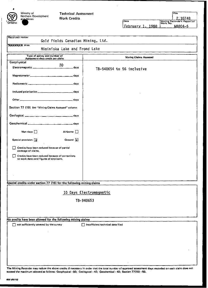
Technical Assessment Work Credits
Oete
February 1. 1988
File
2.10748Mining Recorder 1! Report of Work No.
W8804-6
Recorded Holder
Gold Fields Canadian Mining, Ltd.XXKWWW Area
Miminiska Lake and Frond Lake
Type of turvey and number of Assessment days credit per claim
Geophysical 20
plecti-omagnntic . flays
Radinmfltrio days
Section 77 (19) See "Mining Claims Assessed" column
fienlngiral days
Gfiochemipal days
Man days fj Airborne Q
Special provision Q Ground (x3
|~| Credits have been reduced because of partial coverage of claims.
[~| Credits have been reduced because of corrections to work dates and figures of applicant.
Mining Claims Assessed
TB-940654 to 56 inclusive
Special credits under section 77 (16) for the following mining claims
10 Days Electromagnetic
TB-940653
No credits have been allowed for the following mining claims
f~"| not sufficiently covered by the turvey |"~| insufficient technical data filed
The Mining Recorder may reduce the above credits if necessary in order that the total number of approved assessment days recorded on each claim doet not exceed the maximum allowed as follows: Geophysical - 80; Geologocal - 40; Geochemical - 40; Section 77(19) -60.
tea &S/1 si
Ministry ofNop.'.iern Developmentand Mines '
Ontario
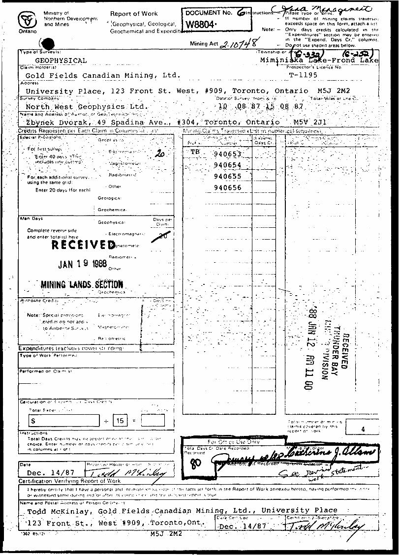
Report of Work
[Geophysical, Geological, Geochemical and Expenditi
DOCUMENT No.
W8804-
.tructions
. Mining Act
lease type orNxmt.H numbei of mining claims traverseu exceeds space on this form, attach a lisi
Note: Only days credits calculated m (lie "Expenditures" section may be enterec: m the "Expend. Days Cr." columns
Do/iot use shaded areas below.Type o* Surveyls)
GEOPHYSICAL Miminiaka1 Prosoec toW L~icence~NoT
T-1195
Township o
'e-Frond ~Lafce"Claim Hoider(s) ""~~"" " " ~" ~- — - — -
J3old Fields Canadian Mining, Ltd. ^^Aaoress
University Place, 123 Front St. West, #909, Toronto, Ontario M5J 2M2Da^e"-o* SJ'vey 'from g, 'p- -*. \ Totai-Miles ot Lne-C;*
ID ,.sQ8 :S7; : i^:;OJ :-8v7. v ;'V'-;",- - ;urvey Comoany \ -' -
Nor itv.: West "Geophysics Ltd .inq
Zb'ynek Dvorak,. 49 Spad'ina Aye.., t364 , ^Toronto-, Ontario; : :.jM5V-.' 231- ;-Cre'diis Reggesicfy pt'r Eacn Claim
Geop'
- Pot
"Enter 40 ctsvs -jTincludes iinftur
For. each additional sutvev - using the same gnd:
Enter 20 days (for each!- Other
Geochernicfli
M*n DaysGeophysical
Complete reverse side and enter totaMsl here
RECEIVED,-
Davs p6
JAN l 9
MINING LANDS SECTIONA.rrotne
Note: 1 Special r'ovi^'C'r1 : f.v.er*d.is ctq not aoD ^
' sp Aiibo-rif Su".c.!, Maq
Expenditures lexcludts oowoi -.n.nType o* Work
P*r*ormed or Cia "i
-r- 15
'lir.HVij.Cia'rf s, Ttqygfs^c! 4'Lrst in. .nutnfer ^;aj se
P'V*
1. ^40,653;
v; ^40654
V 940655
940656
^. 1 'l ' ' -' - A'.\"-~,.- 'l:'
.
CO co
'
ro ra
CD CD
f s? i- s ;--^ m il1
Total Days Credits mjv no JPPO-? o' on T "-. choice. Gnief nu"UH-' o* aavs':rent*s pc" ; ^i'' o columns dt fiqr:
Date
Dec. 14/87Certification Verifying Report of Work
l hereby certify that l have J personal and nt.m.-it-' -CVHV!':;" M -h.- tacts if 'or'h :n the Report of Work annexed hereto, navnq ptrformeo O'witnessnd saniH Ounnq jnU'or oflt'f is ivjrrn . - c'' T"i 'tit' n.''."o-a or" s ;rui?
*nc3 Postal Atjflrcss o' Person Cfl r '.''v
.Todd McKinlay, Gold.Fields-Canadian.Mining, Ltd., University Place
123 Front St. , West 1909 , Toronto,Ont;.M5J 2M2
-Dec .14/8 7 ,; y 36? 66.12'

Ministry ofNorthern Developmentand Mines
Ontario
Geophysical-Geological-Geochemlcal Technical Data Statement
File
TO BE ATTACHED AS AN APPENDIX TO TECHNICAL REPORTFACTS SHOWN HERE NEED NOT BE REPEATED IN REPORT
TECHNICAL REPORT MUST CONTAIN INTERPRETATION, CONCLUSIONS ETC.
Type of Survey(s) GeophysicalTownship or Area Miminiska Lake - Frond Lake Claim Holder(s) Gold Fields Canadian Mining, Ltd,
Survey Company North West Geophysics Ltd.Author of Report Zbynek DvorakAddress of Author 49 Spadina Ave., #304. Toronto. OntCovering Dates of Survey.
Total Miles of Line Cut —
10/8/87 to 15/8/87 M5J 2M2(linecutting to office)
SPECIAL PROVISIONS CREDITS REQUESTED
ENTER 40 days (includes line cutting) for first survey.ENTER 20 days for each additional survey using same grid.
Geophysical—Electromagnetic.—Magnetometer——Radiometric———Other-—————
DAYS per claim
20
Geological.Geochemical.
AIRBORNE CREDITS (Special proviiion credit! do not apply to airborne lurveyi)
Magnetometer. .Electromagnetic. . Radiometric(enter days per claim)
HATE- Dec. 14/87 SIGNATUREi-JjAuthor of Report or Artnt
Res. GeoL. .Qualifications.Previous Surveys
File No. Type Date Claim Holder
MINING CLAIMS TRAVERSED List numerically
TB .94.06.53...(number)
940654
..94.065.g..
940656
TOTAL CLAIMS.
B37 (85/12)
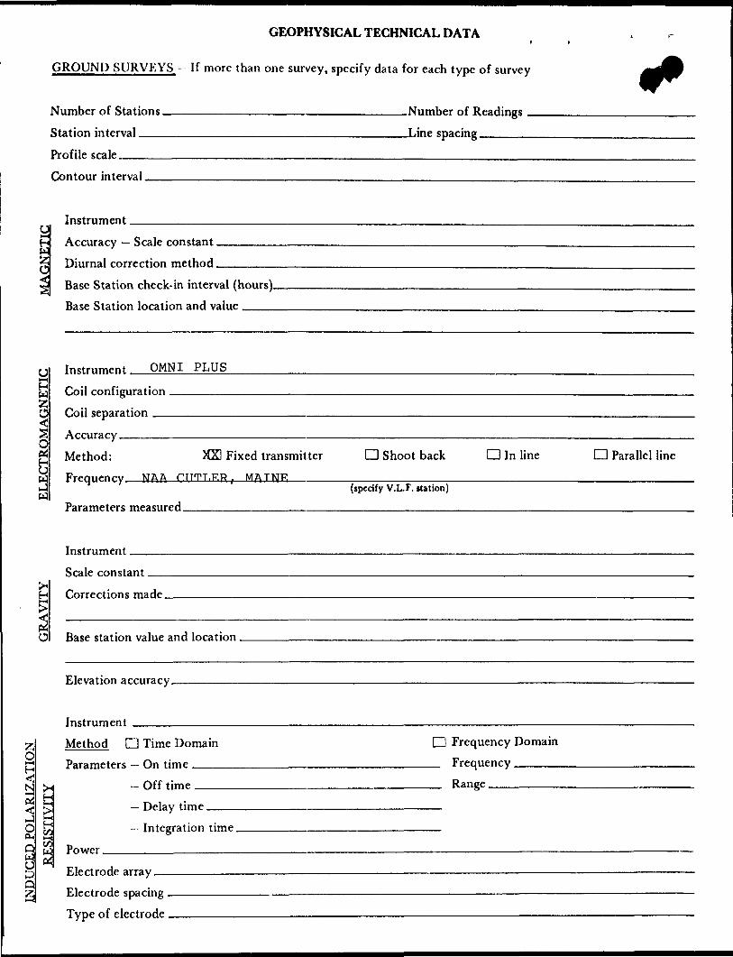
GEOPHYSICAL TECHNICAL DATAi
GROUND SURVEYS — If more than one survey, specify data for each type of survey
Number of Stations—————————————————————————Number of Readings - Station interval .———-———-—.—————-..————————Line spacing ————
Profile scale____________________________________—--———Contour interval.
Instrument —
O
z;O
O
o H c/3
Accuracy — Scale constant. Diurnal correction method.Base Station check-in interval (hours). Base Station location and value ,——
Instrument OMNI PLUS
Coil configuration Coil separation ——
Accuracy————————————————————————————————————————————————————.____—. ^ Method: KS Fixed transmitter D Shoot back D In line CD Parallel line*^
Frpniipnry NAA PTITT.RR , MATNR---^——-—-,-.——^——-—-———.^^———^^———.^^.—.—..^—.(specify V.L.F. station)
Parameters measured ————————————————————————————————————————————————————
Instrument.
Scale constant.
Corrections made.
Base station value and location.
Elevation accuracy.
Instrument ———-————————————————————————————————————————— Method D Time Domain D Frequency Domain
Parameters - On time __________________________ Frequency —————N ^ -Off time___________________________ Range.2 t— ,^ Delay time.
DMr^v
Power.C3 Oip Electrode array.Q Electrode spacing .
Type of electrode ,
Integration time.

SELF POTENTIALInstrument________________________________________ Range.Survey Method -^———^^——^—————————————-—.-—-^^^^——..——^.^^.^—.
Corrections made.
RADIOMETRICInstrument.Values measured.
Energy windows (levels)—^—^—^^^^.^.———————^——^-—^^^^———-——^—-.-——
Height of instrument____________________________Background Count. Size of detector—————————--———-^-—^—-.——.——^—^^-——.—.—.^———.—.—.Overburden -^——————————--—^^^——-————.——..—^.-.—.^-.—.^——-^———
(type, depth — include outcrop map)
OTHERS (SEISMIC, DRILL WELL LOGGING ETC.) Type of survey——^—^———.—-.—..^^—.^^———— Instrument —————^—^——,—————^——^—^——
Accuracy——————————————————————————Parameters measured.
Additional information (for understanding results).
AIRBORNE SURVEYS Type of survey(s)————
Instrument(s) —————(specify for each type of survey)
Accuracy————-————-..————-(specify for each type of survey)
Aircraft used.————-————————-.———————————^^—.——
Sensor altitude.Navigation and flight path recovery method.
Aircraft altitude________________________________Line Sparing Miles flown over total area__________________________Over claims only.

I l
GEOCHEMICAL SURVEY - PROCEDURE RECORD
Numbers of claims from which samples taken.
Total Number of Samples. Type of Sample.
(Nature of Material)
Average Sample Weight——————— Method of Collection————————
Soil Horizon Sampled. Horizon Development. Sample Depth————— Terrain————————
Drainage Development——————————— Estimated Range of Overburden Thickness.
ANALYTICAL METHODSValues expressed in: per cent
p. p. m. p. p. b.
D D D
Cu, Pb,
Others —.
Zn, Ni, Co, Ag, Mo, As.-(circle)
Field Analysis (.Extraction Method. Analytical Method- Reagents Used——
Field Laboratory AnalysisNo. -——-——————
SAMPLE PREPARATION(Includes drying, tcreening, crushing, ashing)
Mesh size of fraction used for analysis ————
Extraction Method. Analytical Method . Reagents Used ——
Commercial Laboratory (. Name of Laboratory—— Extraction Method.—— Analytical Method —— Reagents Used —————
-tests)
.tests)
.tests)
GeneraL General.

O c
l AM
LEGEftHIGHWAY ANO ROUTE No. OTHER ROADS
TRAILS
SURVEYED LINESTOWNSHIPS. BASE LINES. ET( LOTS. MINING CLAIMS. PARC
UNSURVEYED LINES LOT LINES PARCEL BOUNDARY MINING CLAIMS ETC
RAILWAY ANO RIGHT OF WAY UTILITY LINES
NON PERENNIAL STREAM
FLOODING OR FLOODING RIGH SUBDIVISION OR COMPOSITE PI RESERVATIONS
ORIGINAL SHORELINE MARSH OR MUSKEG MINES
TRAVERSE MONUMENT
DISPOSITION OF Ci
PATENT SURFACE 8. MINING RIGSUMFACF HI

(M
.4
*M
ffi
•ft
fV*
>
MIM
INIS
KA
L
AK
E
G-3
32
R) Q 0
w O) M fu O)
M
U*
T) m H > z o
w
m Q i CO
-v
i oo * w
Oft
CO a
RIC
H
LA
KE
G
-388
CD CD OJ
O
M M fv ru
~n
m
:o O c CO o Z * m Q CD
M ffi
OD OD
1
\ t-. fJX o 1 nO CJI
\0 1
i w
in •k
C. C r- (0
09 -i
Z
c O" f* 4^
xi z
^(D
03
q
1 co
p-
2.
o
c
wc
S
cr
^ —
.j
0
~.
0)
OCO
~
*
03
2
r-
3 3
o.n
tn 1*
3-
(Q 1 re 3
"^ J
r
C ̂
^HF
- ——
-^ —
lj
C
S
S
>^
^
*-
*-
m
* "
o
Tl
m
— x*
'1
1 1
—j
t ——
^^
^^J d
^^
•iffifitt
^-5
i ̂
O
-
"W
0s-
r- w
m
,^
/""S
•n
M ""
Ti
M \^
/
^ i
m JI
i
Q**
**
n ^^
^>
o
3J
o—
'
W
WM
M
H
^ DO
0
3
[~5
5 >
Z
"
^^^^
— ̂
^
*^
^^^
^^
^S
K
VV
J ^^
^^^^
^^ '
> m
** -m' ™
s ill 1
c c
Jl
w -
jin
oS
o
(/l C)
t ' m
-3 i n
c gO
O I
ti
z0
w
di
o o o CO o S o
f
i'i
i i
n t
i i
i i,
O
1-
|.
(l,
,,
C,
J-
* -
i/i
i i
' i-
iW
.i
' M
l "'
t. J
l ]
'''
|f
^.
t"
"J
**tf
)33
S
^cS
o^^z"
17""
MZ
" .J^^O
gO
^*
0
PzO
'T
iS^O
ob!
- "^
i — -^
i —
^i
"- t"
^5
xr-5
t
T) '
t I
K
(D
""^
H ;
H
xu
m m
^
0 H
H
ut m
mn
m '
*
JO
2 o
-U
H I
cm
o0)
-o
,
W)
C t
"* a
t ^
- 'rf
"R:
0®
©8^i
\"03^
^
J*
'--.j*
iL
1 t ^E
OF
DOCUMENT
CO 2 CD O f~\
ML.
. .1
C3 ISPOSITIO
N
o m O 33
O Si 2!
p-
^ D C/)
^ -
*
1 -'
^
(l
JJ i/i
n
,ii
i. n
M i
ii.
-*
,. i/i
i
ii:
"i "
M "'K
m
yi x i
.y ^
u ,
S
0
^
>
W
2
-m
3j
n
H -
O
CS
2
S
5 i
0
:O
C
. C
i Z
3
r
i SS
MS??
S S
C
88
:?
m
2
?
r
H
O2l
S
0
: H
3
m
CDr"
H
, --
- \
11
^
' '
i ^)
::::::
•i\ j
J?
^
r i
1 ::
)\ -^
^*-
V J
W
f ^
*', rifl
V '"' '
'gi . —
—
' i -
u r
'•"•
•to
riti-
.' '
'i t
* *;
"
t tn
t
it H
l''
S H
S-
-C 5^'a
H
'5
! m
r-
J |
!^52a^5
-wl^
ws*
nr-
Kof-^
rns^g
o^
f | gP
S^S
i^n
g |
jjC
/jU
i&j-
z-z
en
o33g^
CC
lCD
m
33n
oco
O
^
n
?*
^P
O3
55?
KE^
^S
o P
^
i^
"j
."S
f5
-o
en
>
^ "
m^
5
HD
r\
m
f '
r-
en m
-H
t 0
1
11
A1
Vj i i i i
rn en
m Z o
•* ^
(j
1 ,•li
f ,-
' '
t- "'
. 0
J ve
i J
p"O
0
-^
-N
-N
P
?-
^ i
P^c
o 4'
T-
^
LO
^
5-
Jo"
(^ -
o .
1 "
r* cj
^ :
** I :
^{f
^ ^-
^
"/~--
'-'^
-
t 5
fi'
-v
*; *-
'
(^-7
, '
-c,-
"i-
O
3 Sb
^
r
3 0
^
r-
3 0
p -
^ J5
.
3 ^
*ri
3' T^
1
uc
5o
3-^
.^
,
V
jflP
*^
TJf
^ *-
33 m m 33 rn Z o m 0) •s
/o*
SN
OW
DR
IFT
LA
KE
G
-40
2
H) 5
FR
ON
D
LA
KE
G
-25
2O
) o
(i)
-J
Ul
(O A
03
o* 10 * -JO
O
Naa
Resources
oo
ury
l 3 Q)
3
01
of
p
V —
—
m?
H I S 2
m
m 3D
O 3
w
^25
x m
S o
e
O ~, 2
D o o x w
o^•o I
1
-c -D m 'O -n O
O
O c s m
Z H
S
ICO
CO 13
O
CO o 3D O Z
O
CO
=>
2
LO m S
O
Z C 2 m
Z
O S
C
01
O
Ct t/) z
1
CD w o z n o S 3 S
o o 0 5
w
z c H
5
-t
>
W
HC
33
-^
^K
.
"'l
f-
^
o f-
Z
g
P
00
m Z
C
o01
o 5
cf
2 z
O
ui D
X
T1
>
H
H ^
0
o ^
-n S >
m
-* en T]
> 33
O m
r
tfl m -H o
o <
S
mO
l rr
I
O^
C•^
Z
OD
m
^ m m C/l O
O I
-H
—X
C/
—^
on
O
-n
m m Z
O
. -
--r
- f*
-.
fi i* o
-h
"'

GOto
o oCN
ON.
600S-
2000S.. . —
2400S.
100.0 DM./TO MM CutUr. Udn*
Instrument : OMNI PLUS Vertical Scale: 1 Inch ^
Tx Location : Contour Interval In-phase : Quadrature :
40!!
NAA Cutler, Maine
300ft 100ft l l l l
Oft 200ftl
400ft
GOLDFIELDS MININGVLF-EM SURVEY
PROJECT : MIMINISKA LAKE PROJECT # : GRID A BASELINE AZIMUTH : 165 Deg.
SCALE - 1: 2400/1" - 200ft DATE : 8/22/87SURVEY BY : NWG NTS : 52 P/10FILE: VBLA ___ FREQ.: 24.0 KHz.
NORTHWEST GEOPHYSICS LTD.
3. BO Serial # V87182 Registered User : NORTHWEST GEOPHYSICS LTD.
52P09SW9449 2.10748 FROND LAKE 220
S
CD
CD N)
C(O(b
Z Oajxrn w Ho m o
UJ O W
instrument : OMNI PLUS Vertical Scale: l Inch = 40?S
Tx Location : NM Cutler, Maine Contour Interval : In-phase : —M—M— Quadrature : ....*..-*.....
200ft loon 200ft 400tt
GOLDFIELDS MININGVLF-EM SURVEY
PROJECT : MIMINISKA LAKE PROJECT GRID B BASELINE AZIMUTH : 120 Deg.
SCALE -i 1: 2400/1" - 200ft DATE : 8/22/87 SURVEY BY : NWG NTS : 52 P/10 FILE: VBLB ___ FREQ.: 24.0 KHz.
NORTHWEST GEOPHYSICS LTD.
52Pe9SW9449 2.18748 FROND LAKE 230