Mach4 Overview - trucutcnc.com · Mach4 is a robust and modern CNC control software package. Unlike...
50
Page | 1 TRUCUTCNC MACH4 MANUAL Mach4 Overview__________________________________________ Mach4 is a robust and modern CNC control software package. Unlike Mach3, it was developed on modern 64 bit computer architecture. This means Mach4 performs better and faster on new PC’s available today. Mach4 has no motion controller built in, so the use of an external motion controller is required. All Trucut machine running Mach4 use the Ethernet Smooth Stepper motion controller. One of the most asked questions when you first start Mach4 is…Why do I have the Hobby version. At the top of the Mach4 screen it will say “Mach4 Hobby”. There are two versions of Mach4. Hobby was the first to be introduced and got the most attention from the Mach4 developers, therefore, it is more functional than Mach4 Industrial. What are the real differences? At this point, the only real difference is the price and the fact that Mach4 Industrial lacks some of the things already built into Mach4 Hobby. Rumor is that Mach4 industrial will eventually have built in height control and a few other nice features. We have been using our own external height control for years now and it works as well or better in Mach4 than it does in Mach3. Given that, Mach4 Industrial would not offer any advantage to us over Mach4 Hobby…Other than the title at the top of the screen.
Transcript of Mach4 Overview - trucutcnc.com · Mach4 is a robust and modern CNC control software package. Unlike...
Page | 1
TRUCUTCNC MACH4 MANUAL
Mach4 Overview__________________________________________
Mach4 is a robust and modern CNC control software package. Unlike Mach3, it
was developed on modern 64 bit computer architecture. This means Mach4
performs better and faster on new PC’s available today. Mach4 has no motion
controller built in, so the use of an external motion controller is required. All
Trucut machine running Mach4 use the Ethernet Smooth Stepper motion
controller.
One of the most asked questions when you first start Mach4 is…Why do I have
the Hobby version. At the top of the Mach4 screen it will say “Mach4 Hobby”.
There are two versions of Mach4. Hobby was the first to be introduced and got
the most attention from the Mach4 developers, therefore, it is more functional
than Mach4 Industrial.
What are the real differences?
At this point, the only real difference is the price and the fact that Mach4
Industrial lacks some of the things already built into Mach4 Hobby. Rumor is that
Mach4 industrial will eventually have built in height control and a few other nice
features. We have been using our own external height control for years now and
it works as well or better in Mach4 than it does in Mach3. Given that, Mach4
Industrial would not offer any advantage to us over Mach4 Hobby…Other than
the title at the top of the screen.
Page | 2
TRUCUTCNC MACH4 MANUAL
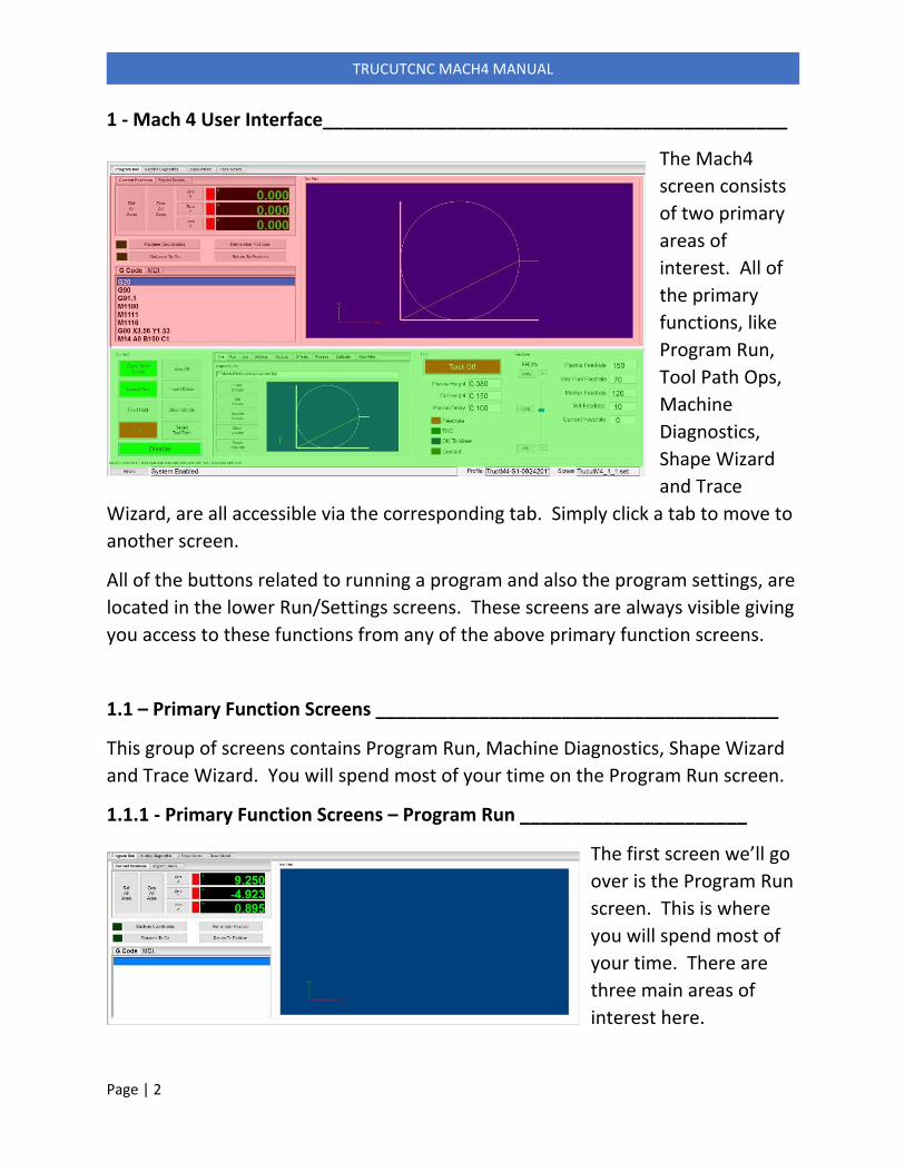
1 ‐ Mach 4 User Interface_____________________________________________
The Mach4
screen consists
of two primary
areas of
interest. All of
the primary
functions, like
Program Run,
Tool Path Ops,
Machine
Diagnostics,
Shape Wizard
and Trace
Wizard, are all accessible via the corresponding tab. Simply click a tab to move to
another screen.
All of the buttons related to running a program and also the program settings, are
located in the lower Run/Settings screens. These screens are always visible giving
you access to these functions from any of the above primary function screens.
1.1 – Primary Function Screens _______________________________________
This group of screens contains Program Run, Machine Diagnostics, Shape Wizard
and Trace Wizard. You will spend most of your time on the Program Run screen.
1.1.1 ‐ Primary Function Screens – Program Run ______________________
The first screen we’ll go
over is the Program Run
screen. This is where
you will spend most of
your time. There are
three main areas of
interest here.

Page | 3
TRUCUTCNC MACH4 MANUAL
The first screen we will go over is the DRO screen.
This screen consists of two tabs. The first displays the machine position DRO’s as
well as buttons to zero one or all axes and reference all axes. The red LED’s
indicate the homed status of the machine. Green LED’s mean the machine is
homed and referenced. The machine must be homed with these LED’s green in
order for Soft Limits to work. Homing is also a good way to return to a known
table position in the event of a program failure. When homing, you will be
prompted to confirm the action by typing “YES”. This is to prevent accidental
homing by hitting the reference button my mistake.
The Machine Coordinates button changes the DRO’s to reflect distance from
machine zero, or the point the machine was referenced to. When this is turned
off, the DRO’s reflect distance from work zero, or the point where Zero All was
pressed. When Distance To Go is active, the DRO’s display the distance to go to
the next coordinate.
Remember Position records the current position in memory and Return To
Position makes the machine return to that position. This differs from GoTo Work
Zero or GoTo Machine Zero in that the remembered position can be anywhere.

Page | 4
TRUCUTCNC MACH4 MANUAL
The Program Extents screen
displays the minimum and
maximum extents of the
program. This is a good way
to determine if the program
will fit on the material you
have on the table.
The GCode window displays
the text for the program
that is currently loaded. As
the program run, it will
cycle through the code in
the window.
The MDI tab allows the
operator to enter GCode
directly and run it. Pressing
Cycle Start will run any GCode entered in the MDI window.
The Tool Path window
graphically displays the
program currently loaded. As
the program runs, the display
will follow the part.
Pressing Regen Toolpath in
the Control button group will
refresh the tool Path display
window.

Page | 5
TRUCUTCNC MACH4 MANUAL
1.1.2 ‐ Primary Function Screens – Machine Diagnostics __________________
The Machine Diagnostics screen is not something used in day to day operation. It
is used more for diagnosis if an issue pops up. There are LED’s, DRO’s, a code
window and tool path display. We can run a job and watch this screen, noting
which LED’s are lit and how the DRO’s are behaving.
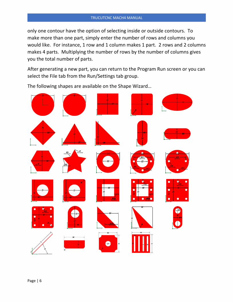
1.1.3 ‐ Primary Function Screens – Shape Wizard ________________________
The Shape Wizard
allows you to
make parts simply
by entering the
part parameters
and pressing Run
Part. There are
30 parts available.
To access the individual parts, click the tabs on top of the window or select the
Parts tab and click on the image of the part you want. The part parameters are
shown on the left with a graphic representation of the part on the right. The
image is static. It does not update to reflect your parameters.
Kerf Compensation, Process, kerf width, lead length and number of columns and
rows are selected on the far left. On parts with inside and outside contours, such
as the one shown above, kerf compensation is figured automatically. Parts with
Page | 6
TRUCUTCNC MACH4 MANUAL
only one contour have the option of selecting inside or outside contours. To
make more than one part, simply enter the number of rows and columns you
would like. For instance, 1 row and 1 column makes 1 part. 2 rows and 2 columns
makes 4 parts. Multiplying the number of rows by the number of columns gives
you the total number of parts.
After generating a new part, you can return to the Program Run screen or you can
select the File tab from the Run/Settings tab group.
The following shapes are available on the Shape Wizard…

Page | 7
TRUCUTCNC MACH4 MANUAL
1.1.4 ‐ Primary Function Screens – Trace Wizard __________________________
The Trace Wizard allows you to use the laser pointer or the optional camera to
locate and mark points around an existing part. The first step is to press the
button on the far left called Zero All Axes. As you progress, the instructions
displayed below the buttons will change to reflect where you are in the process.
The process goes like this…
(1) Move laser or camera to first point and press Zero All Axes.
(2) Press Start. Select a file location and enter a file name.
(3) Press Mark Point.
(4) Move to next point and press Mark Point.
(5) Continue marking points until all points are marked.
(6) Press End to complete the process.
See section 2.15 for further details.

Page | 8
TRUCUTCNC MACH4 MANUAL
1.2 ‐ Settings Screens
The lower panel in the Mach4 screen has all the controls and setting for running
and setting up jobs. This lower panel is always visible even while switching
between function panels above. We’ll discuss each panel in detail.
1.2.1 ‐ Control Button Group ________________________________________
This button groups contains the commonly used
buttons in Mach4. There are other less used features
available in the settings panel, which we will discuss
shortly.
Cycle Start GCode
The Cycle Start button is used to start a job after it is
loaded and the machine is zero’d. Cycle Start can also
be used to resume motion after a Feed Hold. The
torch should be positioned at the desired start point
and Zero All pressed prior to pressing Cycle Start.
Dry Run/Normal Run
Pressing this button toggle between Dry run and Normal Run. When Dry Run is
turned on, the machine will run the part in X and Y axes with no Z motion or
torch. In Normal Run mode the button will ne Green. In Dry Run mode the
button will be Yellow.
Feed Hold
Pressing Feed Hold stops the machine in a controlled manner. After a Feed Hold,
the button text will change to Resume, indicating that pressing the button again
will resume motion.
Page | 9
TRUCUTCNC MACH4 MANUAL
Stop
Pressing Stop stops the machine instantly. Depending on the speed, machine
homing/reference may be lost. If position is lost, resuming will be difficult. For a
controlled stop, Feed Hold is a better option.
Zero All
Pressing Zero All sets work zero to the current position. Press Zero All before
pressing Cycle Start to run a job.
Load GCode
Loads a new GCode file into the system. Files must have a .tap extension.
Close GCode
Closes the currently loaded GCode file.
Regen Toolpath
Pressing this button regenerates the tool path. You may want to regen after
moving and zeroing the torch to refresh the screen display.
Reset
Reset turns off any outputs that may be on and rewinds the GCode program to
the beginning of the file.
Regen Tool Path
Regen Tool Path regenerates the tool path display window.
Enable/Disable
Enables or disables the machine. In an emergency, Disable can be used to Estop
the machine, but this usually results in lost position which requires re‐homing and
loss of the job that is currently running.
Page | 10
TRUCUTCNC MACH4 MANUAL
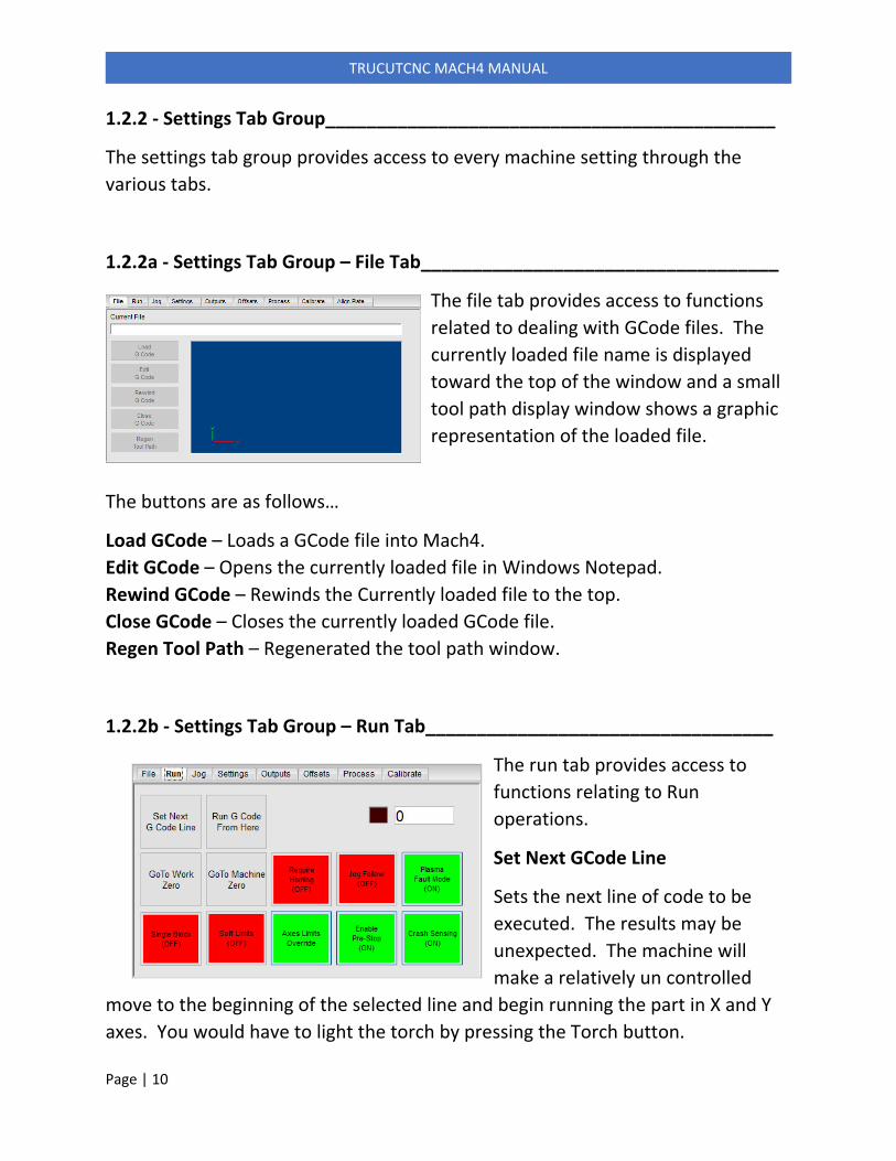
1.2.2 ‐ Settings Tab Group____________________________________________
The settings tab group provides access to every machine setting through the
various tabs.
1.2.2a ‐ Settings Tab Group – File Tab___________________________________
The file tab provides access to functions
related to dealing with GCode files. The
currently loaded file name is displayed
toward the top of the window and a small
tool path display window shows a graphic
representation of the loaded file.
The buttons are as follows…
Load GCode – Loads a GCode file into Mach4.
Edit GCode – Opens the currently loaded file in Windows Notepad.
Rewind GCode – Rewinds the Currently loaded file to the top.
Close GCode – Closes the currently loaded GCode file.
Regen Tool Path – Regenerated the tool path window.
1.2.2b ‐ Settings Tab Group – Run Tab__________________________________
The run tab provides access to
functions relating to Run
operations.
Set Next GCode Line
Sets the next line of code to be
executed. The results may be
unexpected. The machine will
make a relatively un controlled
move to the beginning of the selected line and begin running the part in X and Y
axes. You would have to light the torch by pressing the Torch button.

Page | 11
TRUCUTCNC MACH4 MANUAL
Run GCode From Here
This button allows you to select a line of code in the code window or enter a line
number. The best way to restart is at the beginning of a part. If you have 100
parts on a sheet, and #50 fails, restart at the beginning of #51.
If a part fails, make a note of the line number. If the machine has not lost
position, all you need to do is roll the GCode to the next M114 line, select that
line and press Run GCode From Here.
A dialog box will appear prompting movement to
the start point. Make sure X and Y are selected
and press Move Selected.
After the machine moves to the start point, press
OK making the dialog go away and press Cycle
Start. The job will run from the beginning of the
part selected.
If, for some reason, you lose position by moving the machine after the failure and
pressing Zero All, recovery of the job will not be possible.
As a precaution to this, you can home/reference the machine and position the
material on the table so machine zero and work zero are the same. In this case,
as long as the machine does not lose reference (red reference LED’s), pressing
GoTo Machine Zero will dive the machine to the reference point, which in this
case is also work zero. From there you can use Run GCode From Here to start at
the next part.
The LED beside the Run GCode From Here button indicates the status of the
function. The DRO beside the LED indicates the current line number.

Page | 12
TRUCUTCNC MACH4 MANUAL
GoTo Work Zero
Pressing GoTo Work Zero makes the machine move back to the point that work
zero was set, which is the point at which the Zero All button was pressed.
GoTo Machine Zero
Pressing GoTo Machine Zero makes the machine travel back to the position where
it was homed/referenced. This assumes that the machine is homed with the
Home LED’s beside the position DRO’s lit green.
Soft Limits On/Off
Turns Soft Limits on or off. Soft Limits must be enable in Mach4 configuration for
this function to work. The machine must also be homed with the Home LED’s
beside the position DRO’s lit green.
Single Block On/Off
Single Block is mostly used for troubleshooting a GCode file. When turned on, it
causes Mach4 to execute only one line of code. Pressing Cycle Start again
executes the next line…and so on.
Jog Follow ON/OFF
Jog Follow changes the way the screen looks when jogging and running a job. It’s
a personal preference thing. When Jog Follow is off, the part remains stationary
on the screen and the axis cross hair moves around the part. When Jog Follow is
on, the axis cross hair remains stationary in the center of the screen and the part
moves. One is not necessarily better than the other. Thy them both.
Require Machine Homing
This feature is on by default and will not allow a program to be run unless the
machine is homed. Homing is not required, but it should be done. If you prefer
to run without homing, press Require Machine Homing and turn this feature off.
Page | 13
TRUCUTCNC MACH4 MANUAL
Axes Limits Override Button
This function allows the machine to be jogged off a limit switch. If you hit a limit
switch and the machine stops, press Axes Limits Override which will allow you to
jog the machine off the limit.
Enable Prestop Button
The prestop function allows the torch to shut off before it reaches the end of the
cut, thereby eliminating a stop divot in the cut. Use this button to enable or
disable this feature. Prestop can also be controlled by using M codes M1115 and
M1116 in the GCode. Note that for Prestop to work, there must be a lead‐out or
overburn on the toolpath.
Plasma Fualt Mode
Plasma fault mode detects if the torch goes out while a cut is in progress. If this
happens, the machine will go into a Feedhold state and stop. To resume cutting,
fix the fault and press Cycle Start. The torch will re‐light and the job will continue.
Crash Sensing
This turns the crash sensing feature on and off. The machine must be fitted with
a crash sensing torch holder for this feature to work.
Page | 14
TRUCUTCNC MACH4 MANUAL
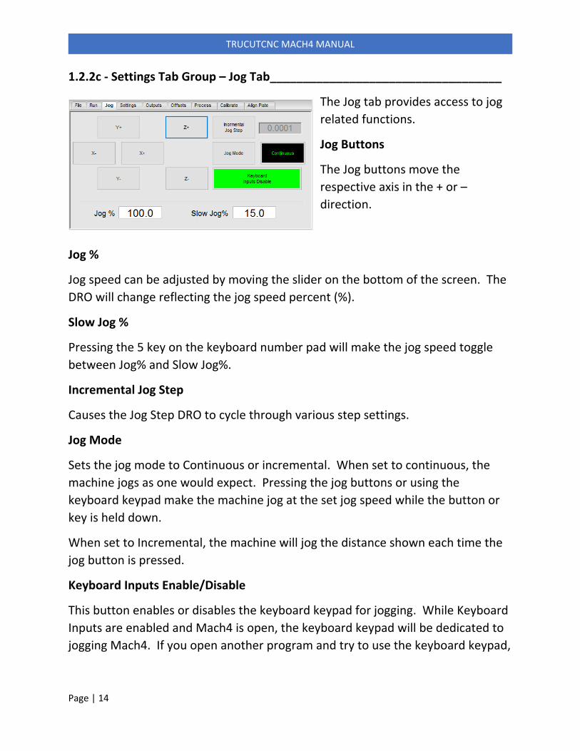
1.2.2c ‐ Settings Tab Group – Jog Tab___________________________________
The Jog tab provides access to jog
related functions.
Jog Buttons
The Jog buttons move the
respective axis in the + or –
direction.
Jog %
Jog speed can be adjusted by moving the slider on the bottom of the screen. The
DRO will change reflecting the jog speed percent (%).
Slow Jog %
Pressing the 5 key on the keyboard number pad will make the jog speed toggle
between Jog% and Slow Jog%.
Incremental Jog Step
Causes the Jog Step DRO to cycle through various step settings.
Jog Mode
Sets the jog mode to Continuous or incremental. When set to continuous, the
machine jogs as one would expect. Pressing the jog buttons or using the
keyboard keypad make the machine jog at the set jog speed while the button or
key is held down.
When set to Incremental, the machine will jog the distance shown each time the
jog button is pressed.
Keyboard Inputs Enable/Disable
This button enables or disables the keyboard keypad for jogging. While Keyboard
Inputs are enabled and Mach4 is open, the keyboard keypad will be dedicated to
jogging Mach4. If you open another program and try to use the keyboard keypad,

Page | 15
TRUCUTCNC MACH4 MANUAL
you will notice that the keys will appear broken. This is because Mach4 has them
captive.

Page | 16
TRUCUTCNC MACH4 MANUAL
1.2.2d ‐ Settings Tab Group – Settings Tab______________________________
This is where you set most of the
program settings.
Switch Offset
Switch offset is the distance between
where the torch touches the material
and where the contact switch makes.
This is adjusted by setting Pierce
Height to 0.25” and pressing Reference Torch. Gauge the distance of the torch
above the material. If it is 0.25”, then the Switch Offset if correct. If it is not, then
adjust the Switch Offset a little and check it again. This is a trial and error process.
Once it is set, you won’t have to worry about it again.
TOM Speed
This is top of material sensing speed. This is the speed at which the torch will
travel down while looking for the material.
TOM Max Travel
This is the max distance that the torch will travel while searching for the material.
If it reaches max travel before finding the material, it will continue as if it found
the material and attempt to cut the part.
Safe Z
Safe Z is the height that the Z will raise to while moving from part to part.
Program End Z
Program End Z is the height at which the torch will raise at the end of the job prior
to traveling back to work zero.
Marker Delay
Marker Delay is the delay in seconds that the machine will pause after lighting the
marker torch. This is similar to Pierce Delay, but works with the marker torch
rather than the cutting torch. This is only applicable to machines using the
plasma marking system.
Page | 17
TRUCUTCNC MACH4 MANUAL
Marker Height
This is the height at which the Z will retract before lighting the marker torch.
With marking, there is no pierce height. The torch retracts to marking height and
the torch lights. This only applies to machines with the plasma marking option.
Drill Delay
Drill Delay is used to apply a pierce delay to the drill function. When you set up a
job in SheetCAM to pierce the center of a hole, the torch will drop down, touch
off, retract to pierce height and light the torch. Drill Delay controls how long the
torch stays on. A delay of 0 (Zero) would be a very shorth burst.
Pre‐Stop Delay
This setting delays turning off the torch when Pre‐Stop is activated. If you find
that the torch is shutting off too early, increase this number a little. For more
information on Pre‐Stop, see that section in this manual.
Reference Torch Button
Pressing Reference Torch will make the torch drive down to the material, stop,
and retract to the pierce height set in the THC control group. It is a good idea to
check the pierce height calibration from time to time by setting the pierce height
to 0.25” and pressing Reference Torch. If the height above the plate is not 0.25”,
Switch Offset on the Setting tab should be adjusted. See the section on
Calibration for more information on pierce height calibration.
Update DRO’s Button
This button reads all configuration data from the M4 configuration file and
populates the screen with it. This process is also automatic so pressing this
button is not necessary. It is here for troubleshooting only.

Page | 18
TRUCUTCNC MACH4 MANUAL
1.2.2e ‐ Settings Tab Group – Outputs Tab_______________________________
The outputs tab provides access to
control and view the status of
common machine outputs. These
outputs are activated and de‐
activated automatically by the
program depending on the process
you are using. You can view their
status or override them here.
Marker Up/Down
Activates the output connected to the marker air cylinder solenoid.
Marker On/Off
Activates the output that lights the marker torch.
Cut Oxygen
Activates the output that opens the cut oxygen solenoid.
Optional Stop
When active, the machine will pause at every instance of M01 it encounters in a
GCode file. Programs have an M01 at the end of every cut. When Optional Stop
is active, the machine will pause at the end of every cut. To continue after an
M01 pause, press Cycle Start. Optional Stop is a good way to make a non‐
emergency controlled pause. Optional Stop is also used when running an Oxy Fuel
job.
THC Enable
THC Enable controls the output that tells the THC to activate.

Page | 19
TRUCUTCNC MACH4 MANUAL
1.2.2f ‐ Settings Tab Group – Offsets Tab_______________________________
The Offsets tab allows access to the
setting related to torch and marker
offsets. Using torch offset is
optional. When torch offset is set
at zero, you would position the
torch at your zero point, then Zero
All, Cycle Start.
If you set the torch offset, you
would use the laser to position the machine, then the machine apples the offset
so the mart cuts in the correct location
Setting An offset
Both marker and torch offsets are set the same way….
(1) Find a clean piece of metal on the table.
(2) Lower the torch close to the metal.
(3) Pierce a hole by pressing the Torch button. (4) Slowly jog the machine so the laser fall into the hole you just pierced.
(5) Press Set Torch Offset (Or Set Marker Offset)
NOTE: Since the laser dot can be easily knocked out of alignment, we
recommend not using it as means of setting the torch zero position.

Page | 20
TRUCUTCNC MACH4 MANUAL
1.2.2g ‐ Settings Tab Group – Process Tab_______________________________
This tab shows the loaded
process and recommended
THC Set Volts. Process
parameters are embedded
into the gcode job file from
SheetCAM and extracted
here. You select the process
in SheetCAM.
Feed Rate Reduction is a way to automatically reduce the feed rate by a set
amount. The published cut speed numbers are almost always too fast. Setting
Feed Rate Reduction to 70% would reduce the published feed rate by 30%. For
instance, a published feed rate of 190IPM would set on the machine at 133IPM.
Selected Process LED’s
These LED’s indicate the process that was selecting in SheetCAM. Some of the
macros (M Codes) that you see in your gcode look at these. When you load a
gcode file, these LED’s will set automatically. The buttons beside the LED’s allow
you to manually select a process if need be.
Current Process LED’s
The Current Process LED’s indicate which process the machine is currently
running. These are used by the system behind the scenes to determine the state
of the machine at any given time. The Fault light indicates that the plasma arc
was lost during a cut.
Page | 21
TRUCUTCNC MACH4 MANUAL
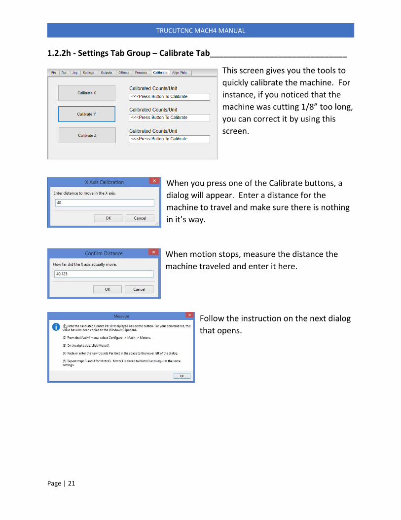
1.2.2h ‐ Settings Tab Group – Calibrate Tab______________________________
This screen gives you the tools to
quickly calibrate the machine. For
instance, if you noticed that the
machine was cutting 1/8” too long,
you can correct it by using this
screen.
When you press one of the Calibrate buttons, a
dialog will appear. Enter a distance for the
machine to travel and make sure there is nothing
in it’s way.
When motion stops, measure the distance the
machine traveled and enter it here.
Follow the instruction on the next dialog
that opens.

Page | 22
TRUCUTCNC MACH4 MANUAL
From the Mach4 menu, go to Configue ‐>
Mach and select the Motors tab. Select
the correct motor. This was displayed in
the instructions dialog. Make a note of the
Velocity and Acceleration numbers, these
will change and you will need to set them
back.
On the lower left corner of the Motors dialog, locate Counts Per Unit. Highlight
the existing number, right click and select Paste. This will insert the calibrated
number. Reset the Velocity and Acceleration back to their original values. From
the factory, these are set to Velocity = 600 and Acceleration = 15.
When finished, restart Mach4. Repeat to calibrate more axes.

Page | 23
TRUCUTCNC MACH4 MANUAL
1.2.3 ‐ Torch Control Group __________________________________________
The torch control group provides access to the
common torch controls, settings and LED
indicators.
Torch On/Off
Turns the cutting torch on or off
Pierce Height
This is the height at which the Z will retract off
the material for initial piercing.
Cut Height
Cut height is only used if the THC is disabled.
Under normal circumstances, cut height is controlled by the THC. When the THC
is disabled, Mach4 will lower the Z to the cut height enters after piercing.
Pierce Delay
Delays motion for the time entered to allow time for the arc to pierce the
material.
Feedrate Antidive LED
This LED will light when the actual feed rate drops below the commanded feed
rate. This is used to lock out the height control when the feed rate drops to
prevent torch dive.
THC LED
This LED will light when the THC is enabled by the software. It can be overridden
from the Outputs tab.
ArcOK LED
This LED will light when the plasma establishes arc transfer. This is a means of
telling the controller that the arc is established and it is OK to move.

Page | 24
TRUCUTCNC MACH4 MANUAL
Contact
This LED will light when the torch contacts the material. To test this LED, you can
lift up on the torch by hand until the torch mount makes contact with the plunger
switch above it. The Contact LED should come on.
1.2.4 ‐ Feed Rate Control Group_______________________________________
The feed rate control group provides
control over the machine cut speeds.
To adjust speeds on the fly, use the FRO
(Feed Rate Override) slider. The machine
speed will change instantly in response
to moving the slider.
The editable fields are Plasma Feedrate,
Oxy Fuel Feedrate and Marker Feedrate.
This how you set the program feedrate
for the job. Any feedrate entered in
SheetCAM will be ignored.

Page | 25
TRUCUTCNC MACH4 MANUAL
2 ‐ Basic Operation ________________________________________________
2.1 ‐ Loading a Job
Select the File tab and press Load GCode. Select the file to load. File type must a
TAP file with a .TAP extension. Make sure you’re not trying to load .DXF or .JOB
files
2.2 ‐ Editing a Job
Select the File tab and press Edit GCode. This opens the file in Windows Notepad.
Don’t do this unless you are comfortable hand writing GCode.
2.3 ‐ Jogging the Machine
Jogging can be done one of two ways…
(1) Open the Jog tab and use the on‐screen buttons to jog the machine.
(2) Use the keyboard keypad. Hold the CTRL key while pressing the following keys. CTRL + 4 and CTRL + 6 jog the X axis, CTRL + 8 and CTRL + 2 jog the Y
axis and CTRL + 9 and CTRL + 3 jog the Z axis.
2.4 ‐ Running a Job
Jog the machine to the zero point on the material, press Zero All then Cycle Start.
Hot keys for Zero All ae CNTL + 1 and Cycle Start is CNTL + 7.
2.5 ‐ Homing the Machine
While it is not necessary, the machine should always be in a homed or referenced
state. When homed, soft limits work, the software knows where the torch is and
top of material sensing is faster. As long as the machine is referenced, you can
always press GoTo Machine Zero to take the torch back to the reference point.
This is handy for crash recovery.
By default, the machine will not allow you to run a program until it is homed. This
can be changed on the Run tab for the current session, but if you restart Mach4, it
will default back to requiring reference.
Referencing is done when you first start up the machine or any time the reference
LED’s beside the position DRO’s go red. Follow these steps to reference….

Page | 26
TRUCUTCNC MACH4 MANUAL
(1) Jog the torch close to the lower left (controller) corner of the machine
without hitting the limit switches.
(2) Press Ref All Axes. (3) A dialog will appear asking you to confirm. Type “YES” and hit OK.
(4) The Z will go up and home to the upper limit, then the X will home to it’s
negative limit and the Y will home to it’s negative limit.
(5) When homing is done, Soft Limits will enable automatically.
If you would like to run without homing the machine, go the the Run tab and turn
off Require Machine Homing.
2.6 ‐ Homing Exercise
This exercise will give you an understanding of how the homing works with
machine and work coordinates.
(1) Home the machine using the method above.
(2) The machine should now be parked and homed. Machine zero will
always remain at this point. When you press Zero All, you are setting
Work Zero.
(3) Jog the machine out into the middle of the table and press Zero All. This
sets Work Zero to the current location. Machine Zero is still where the
machined homed.
(4) Jog the machine again.
(5) From the Run tab, press GoTo Work Zero. The machine will to back to
the point where you pressed Zero All in step 3. Repeat this as many
time as you like. When GoTo Work Zero is pressed, the machine will go
back the last point that Zero All was pressed.
(6) When you’ve seen enough of that, press GoTo Machine Zero.
(7) The machine will go back to the point that it was referenced.
2.7 ‐ Pausing a Job
The best way to pause a job is to turn on Optional Stop, which is on the Outputs
tab. When optional stop is turned on, the machine will pause when it finishes the
cut it is currently on. To resume, just turn off Optional Stop and press Cycle Start.

Page | 27
TRUCUTCNC MACH4 MANUAL
Another method if to press Feed Hold. Pressing Feed Hold makes a controlled
stop near where the button was pressed. Any position moves queued in the
motion controller when the Feed Hold button is pressed will be completed. For
that reason, Feed Hold may not stop on a dime. When Feed Hold is pressed, the
torch will shut off. To resume from Feed Hold, press Cycle Start. When resuming
from Feed Hold, the torch will re‐light.
2.8 ‐ Stopping a Job (Emergency)
To stop in an emergency, press the Disable button on the Mach4 screen or press
one of the red button on the gantry. Estopping in this manner usually results in
lost position which means you may not be able to recover the job. If it’s not an
emergency, Use Optional Stop or Feed Hold instead.
2.9 ‐ Plasma Fault Mode
The machine will go into plasma fault mode if the torch fails to light at the
beginning of a cut. When this happens the machine will go into a Feedhold state.
To recover, fix the issue and press Cycle Start. If the issue is fixed, the torch will
light and the job will continue. If it fails to light again, the machine will go back to
a Feedhold state. This will continue until the torch lights or until you cancel the
job. The fault code on the Hypertherm will tell you what the problem is.
2.10 ‐ Pre‐Stop
Pre‐stop is a feature that turns off the height control and the torch before motion
stops at the end of a cut. This prevents a blow‐out or divot when the torch stops
at the end of the cut. Pre‐stop works by looking ahead in the GCode to the next
line of code. If the next line of code is that last line (the lead‐out) the height
control will disable and the torch will shut off. If you find that the torch is
shutting off too early, you can increase Pre‐Stop Delay on the Settings tab. This
will delay turning the torch off.
IMPORTANT: Pre‐stop will not work unless there is a lead‐out and/or an over
burn set in the job in SheetCAM.
2.11 ‐ Setting Feedrate
The SeriesOne and XT machines do not use a hard coded feed rate in the G‐Code.
Instead, feed rates are set on the machine in Mach3. In the Feed Rate section

Page | 28
TRUCUTCNC MACH4 MANUAL
toward the lower right hand corner of the Program Run screen, you will find three
feed rates…Plasma, Oxy/Fuel and Marker. If running a plasma process, you would
set the plasma feed rate. Oxy/Fuel and Marker feed rates would set speeds for
those processes. The process is decided in SheetCAM.
2.12 ‐ Changing Feedrate During a Cut
To change a feed rate, you can type in a new one at any time, however, the new
speed will not update until the next cut. To change a feed rate on the fly, use the
red Feed Rate Override slider. The number above the slider represents the FRO
percentage. IE: 100 means the machine is running at 100% of the commanded
feed rate. To change the FRO value, drag the slider up or down. To reset it back
to 100%, press the Reset FRO button.
2.13 ‐ Setting Torch Offsets
This section will go over setting tool offsets for the cutting torch. If you have the
Plasma Marking System, see section 4 for more information.
Setting the laser offset means that you must use the laser dot to zero the machine
before every cut. If you would rather just use the torch head itself as the
reference point, skip this step and ensure that both Torch Offset and Marker
Offset are both set to zero on the Settings page.
To set up the torch offset, follow these steps…
Select the Offsets tab in the Setting tab group.
Find a clean spot on a piece of material, drop the torch to 1/8” off the
material and light the torch briefly piercing a small hole.
Press Zero All.
Jog the machine so the laser drops into the hole you just pierced.
Press the button labeled Set Torch Offset. Leave Marker offset set to zero.
If you have the Plasma Marker System, see Chapter 4, Section 4.2.
This process sets the cutting torch offset relative to the laser.
2.14 ‐ Emergency Stop
Emergency Stop can be achieved one of two ways…
Press the Reset button in Mach3 in the lower left corner of the screen.

Page | 29
TRUCUTCNC MACH4 MANUAL
Push one of the red Emergency Stop buttons on the gantry side covers.
Either method will stop the machine. Note that after an E‐Stop, the machine will
most likely lose its position. The faster it was moving when it was E‐Stopped, the
more likely it will be that position has been lost. If you just want to pause the
program and it is not an emergency, use Optional Stop instead.
2.15 ‐ Tracing a Part
The Trucut Tracing Wizard is a utility built into the controller that allows the
operator to place points around a part on the table. This is called a point cloud.
The operator would place points at key locations on the part, such as a corner, a
hole center, etc.
The Tracing Wizard is accessed by pressing the Trace Wizard tab at the top of the
Mach4 screen and brings up a screen like the one below.
From here, just follow the instructions on the screen. Move laser or camera to
the first point you wish to mark and press Zero All Axes.
The screen will change to one similar to the one shown below.

Page | 30
TRUCUTCNC MACH4 MANUAL
Press Start. This will make a file dialog appear. Select a location and file name for
the point cloud file. Do not use a file extension. The program will automatically
add that. The next screen will appear.
The file name and path will show below the buttons. Next, press Mark Point. This
will mark your first point. After marking the first point, jog to the next point and
press Mark Point again.
Continue this until all points have been marked.
After all points have been marked, press End. This will save the point cloud file.

Page | 31
TRUCUTCNC MACH4 MANUAL
You can now use the points as a guide to
complete the part in CAD. Connect the points
using lines and arcs.
You can also mark larger holes using three points,
then in CAD, crate a circle through 3 points. To
make a hole using a single point, place the point
at the center of the hole, then in CAD, create a
circle on that point.
You could end up with something like this.

Page | 32
TRUCUTCNC MACH4 MANUAL
Now you can add details such as corner radii, like this. After the part is drawn, the
points are no longer needed, so you can delete them.
Once the part is done to your satisfaction, save it as a
DXF file, import into SheetCAM and cut.
2.16 – System Hotkeys
Hot keys allow you to perform certain action by using keyboard keys instead on
using the on‐screen buttons. System Hotkeys are as follows…
CNTL + Keypad 1 Zero All
CNTL + Keypad 7 Cycle Start
CNTL + Keypad 2 Jog Y‐
CNTL + Keypad 8 Jog Y+
CNTL + Keypad 4 Jog X‐
CNTL + Keypad 6 Jog X+
CNTL + Keypad 3 Jog Z‐
CNTL + Keypad 9 Jog Z+
CNTL + Keypad 5 Toggle Slow Jog
CNTL + Keypad / Toggle Torch On/Off
2.17 – Running an Oxy/Fuel Job
To run an Oxy/Fuel job you first need to create the job in SheetCAM. The process
is the same as a plasma job, but you use the OXY tool instead of one of the plasma
tools. Follow the instructions below…
Create the gcode in SheetCAM
Hit Load Gcode in Mach4 and select the job you just created.
Turn the THC off on the THC remote by pressing the On/Off button until the
flag on the remote reads “THC Off”
Select the Oxy/Fuel torch lifter using the switch on top of the lifter carriage.
Jog the X and Y to a good zero starting point.

Page | 33
TRUCUTCNC MACH4 MANUAL
Light the torch and job it to a good pierce height.
From the Outputs tab in Mach4, turn on Optional Stop and THC Enable.
Press Zero All then Cycle Start.
The machine will rapid to the first start point and pause for a pre‐heat cycle.
When the material is hot enough to pierce, press the Cut Oxygen button. If it
pierces, press the Cycle Start button. If it does not pierce, wait a little longer and
repeat.
At the end of the first cut, the machine will travel to the second start point and
begin another pre‐heat cycle. Just repeat the above procedure for all cuts. Pre‐
heat will get shorter as you get into the job and the steel gets hotter.

Page | 34
TRUCUTCNC MACH4 MANUAL
3 THC Operation ________________________________________________
3.1 ‐ How it works
The Trucut automatic height control works by reading the tip voltage from the
plasma and raising/lowering the torch to make that voltage match a voltage set
by the operator on the THC remote control. The remote consists of 5 screens,
each containing different functions. Pressing the left and right arrow keys will
move to the next or previous screen. We will discuss each screen and what each
does.
3.2 ‐ Home Screen
The home screen is where you will leave the remote 99% of the time. Here you
can turn the THC on and off by pressing the ON/OFF button, increase the set
voltage (height) by pressing the up arrow and decrease the set voltage by pressing
the down arrow. The home screen also has an indicator tag in the upper right
corner to indicate whether the anti‐dive feature is active. Current tip volts are
displayed above set volts. Press the right arrow to move the next screen.
3.3 ‐ Motion Sensitivity
Motion sensitivity adjusts the reaction time of the THC. A higher number here
makes the THC respond faster to a change in height, but also makes it more
unstable and “jittery”. A higher number is needed for cutting material like
corrugated. A lower number makes the motion more stable and smooth. A
setting of 2 or 3 works well in most cases. To change the sensitivity, press the up
and down arrows. You can set sensitivity between 1 and 6.
3.4 ‐ Antidive Sensitivity
This controls the point at which the internal anti‐dive activates. This is a
percentage. For instance, a setting of 8 would cause anti‐dive to activate at 8%
above the set voltage. If set voltage were 120V and Anti‐Dive Sensitivity were 8,
anti‐dive would engage and inhibit Z motion when it sensed 129.6V.
Why is this important? When the plasma crosses a gap or hole, the tip voltage
goes up and the response from the height control will be to lower the torch to
reduce the voltage. By recognizing that we crossed a gap, we can engage anti‐
Page | 35
TRUCUTCNC MACH4 MANUAL
dive and prevent the torch from diving into the gap or hole and crashing. There is
usually some movement before Anti‐Dive engages.
If you notice the torch diving into holes, lower this number. If you are cutting
material that tends to warp rapidly, like light gauge steel or aluminum, raise this
number to prevent anti‐dive from engaging accidentally. A setting of 10‐12 works
well in most cases. To change the number, press the up and down arrows. To
effectively disable anti‐dive, enter a high number here, such as 30.
When Anti‐Dive engages, a flag labeled ANTI‐DIVE will appear on the upper right
corner of the home page on the remote. When the ANTI‐DIVE flag is visible, there
will be no Z axis movement.
3.5 ‐ Puddle Jump
This number controls when the THC engages. You can use this delay to make the
torch clear slag on thicker metal. For instance, if you pierce ½” plate at .25” and
engage the height control instantly, the torch could dip into the slag puddle left
by the pierce. Increasing the delay would make the torch travel a short distance
at pierce height before dropping to cut height, clearing the slag puddle.
To change this number, press the up and down arrows.
3.6 ‐ Corner Antidive Delay
Corner Anti‐Dive monitors the machine speed and compares the actual speed to
the commanded speed. If the actual speed is less than the commanded speed,
Corner Anti‐Dive locks the THC to prevent the torch from diving into corners. If
we engaged this feature immediately, the THC would not enable until the
machine reached commanded speed. Corner Anti‐Dive Delay adds a delay so the
THC can enable and drop to cut height in a timely manner. 1‐2 seconds works
well and should be at least ½ second more than Puddle Jump.
3.7 ‐ Manual Height Control
This screen allows you to control the torch height manually while cutting. To use
this feature, the THC must be turned off on the Home screen. This feature is
particularly useful for those using an Oxy/Fuel torch where no voltage based
automatic height control is available.
Page | 36
TRUCUTCNC MACH4 MANUAL
Basic Operation
For the height control to operate properly, you must first set the target voltage,
or set voltage. This is done using the up and down arrow keys on the home page.
There are three ways to determine a starting point for the set voltage.
Open the Hypertherm manual that came with your plasma and look at the
cut chart for the amperage and consumable you are using. Look under Best
Quality Settings and enter the voltage from the chart on the THC remote.
Select the desired process from the Presets tab. This will load process
parameters and display the correct set voltage for the process.
Turn off the THC from the home screen and cut a small sample part. Pay
attention to the Tip Volts on the remote. Set the set volts to the same
number. This will get the height close. After you start cutting you can dial
it in.
Once you have a starting point for the set voltage, you can dial it in closer while
it’s cutting. As you change the set volts while cutting, the height will respond
instantly. If the height looks too high, lower the set volts. If it looks too low,
raise the set volts.
Once you have it dialed in, make a note of that number for the amperage and
material you are running. After a few jobs, you’ll remember the set volts, and if
you notice it is off a little, you can adjust it on the fly without ruining the job. In
many cases, the book settings are accurate and others they are not.
Pierce height has little effect on the cut height since cut height is controlled solely
by arc voltage. If the pierce height is off when the cut begins, the height will
move rapidly to the cut height determined by the set volts entered on the home
screen when the THC enables.
3.8 ‐ Saving THC Settings
Any parameters that you change on the THC remote control will be automatically
saved to non‐volatile memory when you cycle the THC from on to off. If you
power down without turning the THC off on the remote, the parameters that
were last saved will be loaded on start‐up.

Page | 37
TRUCUTCNC MACH4 MANUAL
NOTE: The DL05 PLC EEPROM memory has a maximum limit of 100,000 writes.
That means that after 100,000 save cycles, the PLC memory may become
unreliable. Under normal, or even heavy use, this limitation should not be an
issue.
While the PLC is saving data, the remote display will show a PLC COM Timeout
error. This is normal.
If you would like to limit the number of EEPROM writes to the PLC, just power
down the controller without cycling the THC to off. This works great if you cut the
same material most of the time.

Page | 38
TRUCUTCNC MACH4 MANUAL
4 ‐ Plasma Marking System _________________________________________
4.1 ‐ How it works
Plasma marking has been around for years but only available on expensive hi‐
definition plasma machines. All of that changed when Hypertherm came out with
their Powermax 45XP. The 45XP can operate at very low current setting (as low
as 10A) and still use a contact arc start method.
Our plasma marking system includes a new Powermax 45XP with a machine torch.
The marker torch is mounted beside the cutting torch on it’s own lifter. When the
system switches to marking, which is set up in SheetCAM, control switches from
the cutting torch lifter to the marker torch lifter.
The marker torch must be set up in Mach3 with an offset. This offset either….
1. Tells the software the X and Y offset of the marker torch from the laser, or…
2. Tells the software the X and Y offset of the marker torch from the cutting
torch.
If you set a marker torch offset relative to the laser, then you must also set a
cutting torch offset relative to the laser. You will then use the laser to set your
zero before running a job.
If you set a marker torch offset relative to the cutting torch, then you would leave
the cutting torch offsets at zero and use the actual cutting torch position to set
zero before running a job.
4.2 ‐ Setting the Torch Offsets
to set the marker tool offset, first figure out if you want to use the laser all the
time to reference zero on the machine. If you do, follow these instructions…
1. Find a clean location on a piece of material and jog the torch to that
location.
2. Lower the cutting torch to about 1/8” off the material, press Zero All and
press the Torch button briefly to pierce a small hole.
3. Make sure the position DRO’s are zero’d out. If they are not, press Zero All
now.
4. Jog the machine so the laser dot falls into the hole you just pierced.

Page | 39
TRUCUTCNC MACH4 MANUAL
5. Go to the Offsets tab and press the button called Set Torch Offset. This will set the offset distance between the laser and cutting torch.
6. Repeat steps 1 – 5 but instead of firing the cutting torch, use the marking
torch. Note that when doing this with the marking torch, the torch may not
pierce all the way through. Just put the laser dot on the mark.
7. On the Offsets tab, press Set Marker Offset. This will set the offset distance
between the laser and the marker torch.
If you don’t want to use the laser at all, follow these steps…
1. Lower the marking torch by pressing Marker Up/Down, light the marking
torch by pressing Marker On/Off and make a visible mark.
2. Press Zero All. 3. Raise the marking torch by pressing Marker Up/Down again. Jog the
machine so the Cutting torch is centered on the mark you made with the
marking torch.
4. Go to the Settings screen and press the Set Marker Offset button. This will
set the marker torch offset relative to the cutting torch.
Page | 40
TRUCUTCNC MACH4 MANUAL
5 Calibration __________________________________________________
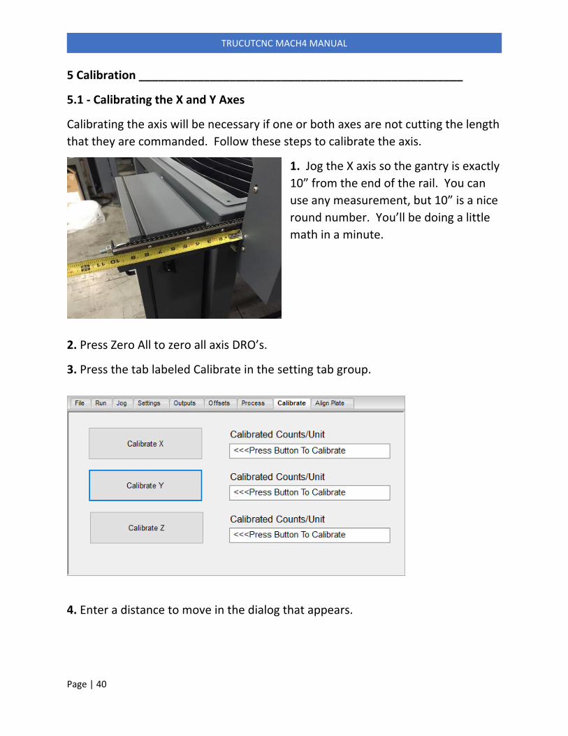
5.1 ‐ Calibrating the X and Y Axes
Calibrating the axis will be necessary if one or both axes are not cutting the length
that they are commanded. Follow these steps to calibrate the axis.
1. Jog the X axis so the gantry is exactly
10” from the end of the rail. You can
use any measurement, but 10” is a nice
round number. You’ll be doing a little
math in a minute.
2. Press Zero All to zero all axis DRO’s.
3. Press the tab labeled Calibrate in the setting tab group.
4. Enter a distance to move in the dialog that appears.

Page | 41
TRUCUTCNC MACH4 MANUAL
5. Enter how far the
machine actually moved in
the next dialog that
appears. When measuring,
don’t forget to subtract your
beginning measurement.
6. The calibrated steps per unit will display next to the button. This number will
also be copied to the Windows clipboard.
7. In the Mach4 menu, go to Configure ‐> Mach…
8. Select the Motors tab.
9. Delete the existing number for Steps Per Unit.
10. With the cursor in the blank data field, right click and select Paste. This will
paste the calibrated number into the Steps Per Unit field.
11. Restart Mach4 and repeat for the Y axis. It is not
necessary to calibrate the Z axis, but you can if you
want to.

Page | 42
TRUCUTCNC MACH4 MANUAL
5.2 ‐ Calibrating Pierce Height
In order for Pierce Height to work properly, the software needs to know the
distance that Z travels after it touches and makes contact with the floating head
switch. To do this, follow these steps….
1) Check that the floating head switch is connected and working
properly by lifting up on the torch so it makes contact with the
floating head switch mounted above the floating head. When this
switch makes contact, the yellow LED labeled Contact should
come on. If it doesn’t, do not continue. Automatic referencing
will not work.
2) Set Pierce Height to .25” and find a piece of ¼” material you can
use as a feeler gauge. We use a piece of ¼” cold rolled. A ¼” drill
bit works well also.
3) Jog the torch over some fairly heavy material that will not distort
when the torch touches off to it.
4) Jog the Z down to about ½” off the material and press Zero All.
5) Press “Reference Torch” on the Settings tab.
The torch should go down, touch off and come back up to .25”. Use your ¼”
feeler gauge to check the torch height. If it is too low increase Switch Offset (Just
to the left of the Reference Torch button).
For Instance, If the height is less than .25 and the current switch offset is ‐0.55,
enter ‐0.65 and repeat the above process. Note that there must always be a – in
front of the number. If it is still not right, re‐adjust the Switch Offset and repeat.
This a trial and error process, but the good news is that once it’s done you
shouldn’t have to do it again.

Page | 43
TRUCUTCNC MACH4 MANUAL
5.3 ‐ Squaring the Gantry – SeriesOne Machines
To square the machine, you first need to cut a square and determine if it is square
or skewed. If it is skewed, the machine is out of square. To square the machine,
you will loosen the belt tension on one side of the machine. With the tension
loose on the belt, you can skip teeth on the timing belt to move this side of the
gantry fore or aft depending on your test square.
Measure the cut square corner to corner or put a framing square on it to
determine which direction to move the gantry side. Again, for coarse adjustment
more than 1/16" ‐ 1/8", loosen the timing belt tension and skip a tooth. For fine
adjustment, loosen one side of the drive chain and tighten the other. For
instance, loosen the rear chain bolt 1/2 turn and tighten the front bold 1/2 turn.
See the graphic examples below. The skew in these images is exaggerated for
graphic purposes. You will not be able see the skew by eye.
5.4 ‐ Squaring the Gantry ‐ XT Machines
XT machines are driven independently on each side of the gantry. These
machines have squaring stops on the rear of the table. To square the gantry do
the following…
1) Ensure that the racks are engaged.
2) If the machine is on and Mach3 is running, Jog the machine to the rear
of the table close to the rear limit trigger pin. If the machine is not
running and Mach3 is shut down, you can disengage the racks, move the
gantry to the rear of the machine, then re‐engage the racks.
3) Exit Mach3 and turn the machine controller OFF. Ensure racks are
engaged.

Page | 44
TRUCUTCNC MACH4 MANUAL
4) Pull the gantry rearward until it rests against the squaring stops.
5) Turn the machine controller ON and start Mach3.
6) The machine will be resting on the rear limit. From the Run tab, enable
Axis Limit Override so you can jog off the limit.

Page | 45
TRUCUTCNC MACH4 MANUAL
6 ‐ G&M Codes __________________________________________________
G00 ‐ Rapid move at the speed defined in motor tuning. Speed can be altered by
setting a reduction percentage in Jog Speed.
G01 ‐ Feed rate move. G01 requires that a feed rate be set as well as destination
coordinates.
G03/G03 ‐ Circular interpolation at a given feedrate.
G02 Clockwise arc motion at feedrate.
G03 Counterclockwise arc motion at feedrate.
The clockwise direction is determined by viewing the arc from the positive side of
a vector normal to the arc plane.
Like the G01 command, G02 and G03 require a feedrate (F) as well as destination
(or distance) coordinates (X, Y, and/or Z). The feedrate will default to the current
feedrate if it has been commanded previously in the program.
G04 ‐ Makes the machine pause for a given number of seconds. For instance, to
pause for ¾ of a second, the code would look like….
G04 P0.75
G52 ‐ Temporarily shifts program zero to a new location. G52 is used to shift
program coordinates when tool offsets are used.
M14 ‐ Initiates the cutting sequence, including TOM sensing and torch ignition
M15 ‐ Initiates the cut end sequence.
M1000 ‐ Moves Z axis to Safe Z.
M1101 – Enables THC.
M1102 – Disables THC.
M1103 – Turns cut oxygen on.
M1104 – Turns cut oxygen off.
M1105 – Moves Z axis to End Z.

Page | 46
TRUCUTCNC MACH4 MANUAL
M1106 – Set Marker Offset.
M1109 – Zero any work coordinate offset.
M1111 – Set cutting torch offset.

Page | 47
TRUCUTCNC MACH4 MANUAL
7 Trouble Shooting _________________________________________________
7.1 ‐ THC does not appear to be working.
Before getting into any troubleshooting, make sure the THC is not functional by
cutting a circle from the Shape Wizard. While it’s cutting, put your finger on the
silver motor coupler on the Z lifter. You should feel movement. Even if the
material is flat, you should feel slight movement. If you feel movement, the THC is
working correctly. If you feel no movement, follow these steps….
1) Make sure THC is turned on from the remote. From the home screen on the
remote, press the On/Off button.
2) Make sure Set Voltage is set correctly.
3) Open the controller box and look for the DL05 PLC. This will be on the left side
just below the large power supply. There should be two small LED lights lit on the
right side with two other LED’s flashing rapidly. The two on the top indicate
power is getting to the PLC. The two below indicate that the remote is
communicating with the PLC.
If you don’t see any LEDS on the PLC, check the two white circuit breakers toward
the top of the controller. One is labeled C2 and one is labeled C20. C2 feeds the
Rhino power supply for the PLC. Both breakers should be showing a red window.
If both breakers are ON, then the Rhino 24V power supply. It should have a
steady light. If the light on the Rhino is flashing, this indicates a short circuit. Call
for further assistance.
If the Rhino power supply is showing a steady light and the PLC is still not showing
power LEDs, the PLC may be faulty. Call for further assistance.
4) Check that the THC has not been disabled in SheetCAM. THC can be disabled
by setting specific operation variables.
5) If none of the above helps, call for further assistance.

Page | 48
TRUCUTCNC MACH4 MANUAL
7.2 ‐ Torch is dragging from the start of the cut.
If the torch fires while still touching the material and continues to drag, you have
two issues…
1) The pierce height is too low and probably needs calibrating. See the
section in this manual regarding pierce height calibration.
2) The cut height is too low. Using the THC remote, raise the set voltage
on the remote. If set voltage it too low, the torch will drag. You can find
set voltage in the manual for your plasma unit. It is usually called arc
voltage in the manual. You can also select the desired process from the
Process tab. You will be prompted with the correct arc voltage setting.
7.3 ‐ Torch pierces at the correct height, then crashes.
This is an indication that the set volts on the THC remote is set too low. Raise set
volts to raise the cut height.
7.4 ‐ Cut height appears to be too high.
Remember, set volts on the THC remote equals height. If the cut height is too
high, lower the set volts.
7.5 ‐ Torch dives at the end of a cut.
This can happen on inside contours where the metal drops away as the cut
contour is closed and the torch completes the lead out phase of the cut. During
this phase, there is no metal under the torch and the tip voltage goes up. The
response from the height control is to move the torch down to compensate for
the increase in arc voltage.
The easiest way to avoid this is to make sure Pre‐Stop is turned on. See section
1.2.2b for more information on Pre‐Stop.
If you are not using Pre‐Stop, decreasing the Antidive Sensitivity will help. IE:
Reduce the number from say, 10% to 6%. See section 3.4 for more information.
7.6 – THC will not track rapid changes in height.
If the THC is crashing into the material rather than tracking it up, either the THC is
not working (See section 7.1) or the height is changing faster than the THC can
respond. To increase the THC response time, go to the Motion Sensitivity screen
Page | 49
TRUCUTCNC MACH4 MANUAL
on the THC remote and increase the number. Do not increase more than one
number at a time. Increasing this too much may cause the THC to become
unstable.
7.7 – Torch touches off but does not light.
This if almost always caused by a fault on the plasma power supply. If the LED
beside the torch button lights as it is supposed to, Mach4 has sent the start signal
to the plasma. On PM65‐125 power supplies, look for a yellow fault light on the
plasma. If there is a yellow fault light, there will be also be a code number shown
in the window. Look up that code in the plasma manual for an explanation of
what is going on.
7.8 – Torch lights but does not move.
Mach4 will wait for a signal from the plasma power supply indicating that it has
established an arc before moving. If the torch lights but the machine does not
move, it is likely because the plasma has not sensed a good arc transfer. This can
be caused by a bad ground or pierce height being too high. Check and clean your
grounds and try lowing the pierce height. When a good arc transfer is sensed, the
Arc OK LED will light. The machine will not move until this LED is lit.
7.9 – The machine will not jog.
When you try to jog, are the DRO number moving?
If YES…
Mach4 is likely not connected to the motion controller. Mach4 is senting signals
to the motion controller, but because there is no connection, the motion
controller is not responding. Shut down the controller and close Mach4, then
turn on the controller and start Mach4. You should see the Warp9 splash screen
followed by the Mach4 screen. If Mach4 fails to connect to the motion controller,
an error will appear. If this persists, call for further assistance.
If NO…
From the Jog Tab, ensure that jog mode is set to Continuous and that Keyboard
Inputs are enabled (green button). Also ensure that slow jog is not active. If it is

Page | 50
TRUCUTCNC MACH4 MANUAL
and you have a small number entered in Slow Jog, the machine can jog so slowly
that it appears to be not moving.
7.10 ‐ Jog speed seems slow.
On the Jog Tab there is a setting for Slow Jog. If slow jog is active, the machine
will jog at the speed entered for Slow Jog. To toggle between fast jog and slow
jog, use the keypad and hit CNTL + 5.
7.11 – Pierce height does not match what is entered on the screen.
If the actual pierce height does not match what is enter on the screen, the pierce
height needs to be calibrated. See section 5.2 for more information.
7.12 – The machine is not cutting the correct length and/or width.
For instance, you cut a 10” square and it measures 10.125”. This is usually
because steps per unit are incorrect and the machine needs to be calibrated. See
section 5.1 for more information on calibrating the X and Y axes.
7.13 – Torch shuts off in the middle of a cut.
This is almost always a plasma fault. First determine if the LED beside the torch
button stays lit after the torch shuts off. If it does, the problem is with the plasma
power supply. When the plasma shuts off on it’s own, it will show a fault number
in the LCD window. Those faults codes are in the plasma manual. Common codes
for the Powermax65‐125 are….
0‐12…Low input gas pressure.
0‐20…Low gas pressure.
0‐21…Gas flow lost while cutting.
0‐22…No gas input.
0‐30…Torch consumable stuck (Replace swirl ring).
0‐50…Retaining cap off.
0‐51…Torch is on at power up.