LineIQ-35 User's Manual v0.1 - Experts in Power Quality ... · User Manual Version 0.1 11 ... (e.g....
23
User Manual Version 0.1 11 March 2016
Transcript of LineIQ-35 User's Manual v0.1 - Experts in Power Quality ... · User Manual Version 0.1 11 ... (e.g....

User Manual
Version 0.1 11 March 2016

File: LineIQ-35 User's Manual v0.1.docx page 1 of 22

File: LineIQ-35 User's Manual v0.1.docx page 2 of 22
Copyright © GridSense Inc 2010-2012 The material presented in this manual is copyright protected by GridSense Inc. Any reproduction in whole or in part for any purpose without the prior written consent of GridSense Inc is strictly prohibited. Information in this document is subject to change without notice. All trademarks are the property of their respective owners.

File: LineIQ-35 User's Manual v0.1.docx page 3 of 22
Amendments Version Date Author Comments
0.1 22NOV2012 Adam Goldsmith Initial document
File: LineIQ-35 User's Manual v0.1.docx page 4 of 22
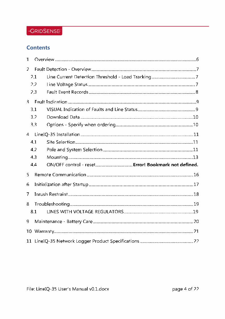
Contents 1 Overview ..................................................................................................................................... 6 2 Fault Detection - Overview ................................................................................................... 7 2.1 Line Current Detection Threshold - Load Tracking ......................................... 7 2.2 Line Voltage Status ..................................................................................................... 7 2.3 Fault Event Records .................................................................................................... 8 3 Fault Indication ......................................................................................................................... 9 3.1 VISUAL Indication of Faults and Line Status ...................................................... 9 3.2 Download Data .......................................................................................................... 10 3.3 Options - Specify when ordering ......................................................................... 10 4 LineIQ-35 Installation .......................................................................................................... 11 4.1 Site Selection ............................................................................................................... 11 4.2 Pole and System Selection ..................................................................................... 11 4.3 Mounting ...................................................................................................................... 13 4.4 ON/OFF control - reset................................... Error! Bookmark not defined. 5 Remote Communication .................................................................................................... 16 6 Initialization after Startup .................................................................................................. 17 7 Inrush Restraint...................................................................................................................... 18 8 Troubleshooting .................................................................................................................... 19 8.1 LINES WITH VOLTAGE REGULATORS ................................................................. 19 9 Maintenance - Battery Care .............................................................................................. 20 10 Warranty................................................................................................................................... 21 11 LineIQ-35 Network Logger Product Specifications .................................................. 22

File: LineIQ-35 User's Manual v0.1.docx page 5 of 22
Table of Figures No table of figures entries found.

File: LineIQ-35 User's Manual v0.1.docx page 6 of 22
1 Overview The LineIQ-35 (Pole Mounted Sensor), is a solar powered Network Logger for use on 3 phase 3 wire, or 1 phase 2 wire, single earth systems or SWER overhead Lines for detection of Permanent, Transient or Self Clearing faults. The LineIQ-35 incorporates a dual Magnetic Field and single Electric Field detection system for greater accuracy in fault sensing. These detectors use an Automatic Gain control system that allows tracking of line currents from 25 Amps to 1000Amps and Fault currents from 5 Amps for Earth Fault or 25 Amps for Three Phase Fault up to 25kAmps.

File: LineIQ-35 User's Manual v0.1.docx page 7 of 22
2 Fault Detection - Overview The LineIQ-35 continuously monitors the line condition through ambient electric and magnetic fields. Both horizontal and vertical magnetic fields are sensed. Detection and classification of line fault conditions are based on changes in the levels of the magnetic & electric fields and their history. 2.1 Line Current Detection Threshold - Load Tracking The LineIQ-35 maintains two reference levels for line loading - a short term (fast filter) prior to fault and a long-term (slow filter) max load value. These values are used in conjunction with the line voltage status (E field on/off) to determine the optimum threshold for fault current detection and also to discriminate between normal load changes, fault currents and events during switch-on. To be recognized by the LineIQ-35, the fault current magnetic field level must instantaneously exceed a threshold of which is typically set at 200% of normal load current (as observed via the magnetic fields at the LineIQ-35), this is known as an Arming. A second and higher threshold (500%) for magnetic field levels is also used to further classify fault conditions. 2.2 Line Voltage Status To recognize return of line voltage after voltage loss, the LineIQ-35 requires the restored voltage to be present (i.e. above the programmed minimum threshold) for a continuous period of 60 seconds (E continuous). Faults are considered a transient fault if loss off voltage is detected and restored within 60 seconds after an arming event occurs. The time and date of voltage loss & restoration is saved for both permanent and transient faults indicating outage duration.

File: LineIQ-35 User's Manual v0.1.docx page 8 of 22
2.3 Fault Event Records The details of each fault/event are recorded in a Date Time Stamped (DTS) format within the LineIQ-35. There is 61KB of event memory available. The amount of memory required for each event is variable depending on the number of current and voltage changes during the arming period. As a guide a typical event will be approx. 1000 Bytes. Fault/Event Types
SI (Short Interruption) Not on Fault Path, voltage lost and restored within 1 (one) minute.
LI (Long Interruption) Not on Fault Path with voltage lost for greater than 1 minute.
FP (Self Clearing Fault) On Fault Path (FP) high current without loss of voltage
FP LI (Permanent Fault) On Fault Path (FP) high current with voltage lost and restored within 1 minute.
PR (Power Return) A return of Power.
File: LineIQ-35 User's Manual v0.1.docx page 9 of 22
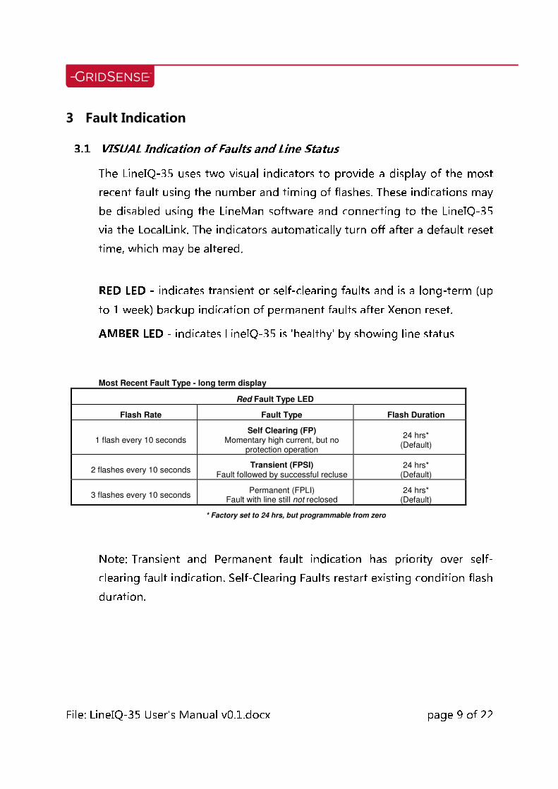
3 Fault Indication 3.1 VISUAL Indication of Faults and Line Status The LineIQ-35 uses two visual indicators to provide a display of the most recent fault using the number and timing of flashes. These indications may be disabled using the LineMan software and connecting to the LineIQ-35 via the LocalLink. The indicators automatically turn off after a default reset time, which may be altered. RED LED - indicates transient or self-clearing faults and is a long-term (up to 1 week) backup indication of permanent faults after Xenon reset. AMBER LED - indicates LineIQ-35 is 'healthy' by showing line status
Most Recent Fault Type - long term display
Red Fault Type LED
Flash Rate Fault Type Flash Duration
1 flash every 10 seconds Self Clearing (FP)
Momentary high current, but no protection operation
24 hrs* (Default)
2 flashes every 10 seconds Transient (FPSI) Fault followed by successful recluse
24 hrs* (Default)
3 flashes every 10 seconds Permanent (FPLI) Fault with line still not reclosed
24 hrs* (Default)
* Factory set to 24 hrs, but programmable from zero Note: Transient and Permanent fault indication has priority over self-clearing fault indication. Self-Clearing Faults restart existing condition flash duration.
File: LineIQ-35 User's Manual v0.1.docx page 10 of 22
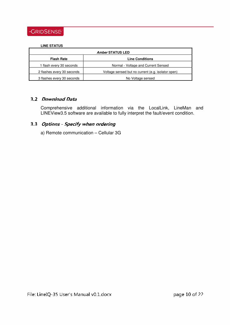
LINE STATUS
Amber STATUS LED
Flash Rate Line Conditions
1 flash every 30 seconds Normal - Voltage and Current Sensed
2 flashes every 30 seconds Voltage sensed but no current (e.g. isolator open)
3 flashes every 30 seconds No Voltage sensed 3.2 Download Data Comprehensive additional information via the LocalLink, LineMan and LINEView3.5 software are available to fully interpret the fault/event condition. 3.3 Options - Specify when ordering a) Remote communication – Cellular 3G

File: LineIQ-35 User's Manual v0.1.docx page 11 of 22
4 LineIQ-35 Installation 4.1 Site Selection LineIQ-35 Network Loggers should be mounted at regular intervals on the distribution system determined by local conditions and at strategic locations, for example, beyond isolating switchgear, branch lines at tee-offs (at least one span away from the tee-off on the load side), where the line enters and leaves inaccessible areas and as otherwise required to optimize fault location and isolation. The LineIQ-35 will operate on both 50Hz and 60Hz systems.
Note: GridSense recommend one installation for every 5km of line. 4.2 Pole and System Selection 4.2.1 Always keep in mind that the conditions for triggering at the LineIQ-35 mounting location are: "100% or more increase in the magnetic field (arming period), followed within 1 minute by complete loss of alternating electric field, i.e. all 50 or 60Hz voltage". These requirements MUST be met. 4.2.2 Note: DC voltage, eg. Telephone and train lines will not affect LineIQ-35 operation. 4.2.3 Select the cleanest pole possible and do not use on Tee-off poles or those with concentrated sources of magnetic fields such as those with transformers, underground cables, magnetically operated switches etc. The ideal application ensuring correct operation is single circuit clean pole.
File: LineIQ-35 User's Manual v0.1.docx page 12 of 22
4.2.4 At `tees' mount the LineIQ-35 a span away from the junction, on the load side, so the fields from the faulted section will not trigger the `non' faulted line LineIQ-35. 4.2.5 Use on 3 wire or SWER radial systems with only one earth, usually the star point of the supply transformer. 4.2.6 If earth wires, earthed messenger or catenaries are used on the pole these must be cut and terminated on an insulator either side of the LineIQ-35 so that earth currents cannot flow and trigger the LineIQ-35 beyond the fault. Alternatively install a LineIQ-60 sensor. 4.2.7 Do Not use the LineIQ-35 in the following locations: - 3 phase lines or single phase, 2 wire lines that are fused or protected by single pole reclosers, as the remaining live conductors will prevent triggering (Transient & Permanent faults) as a result of continuous E-field readings. - 4 wire HV systems with MEN (Multiple Earthed Neutral) as fault or single-phase load current can flow to earth beyond the fault and cause “non fault path” triggering. - Lightly loaded lines, below a nominal load of 7 amps (may differ as a result of mounting distance) the magnetic sensors are near the minimum capacity and may not detect a fault. This would be made apparent by two amber LED flashes every 30 sec, either move the LineIQ-35 closer to the conductors or relocate to a heavier loaded line.

File: LineIQ-35 User's Manual v0.1.docx page 13 of 22
4.2.8 The LineIQ-35 should be kept the following distances from nearby lines that remain energized after a fault: Line Voltage Separation Line Voltage Separation
11kV 25m 66kV 100m
22kV 35m 132kV 200m
33kV 50m 275-400kV 500m
Note: For other voltages the distances are proportional to voltage 4.3 Mounting 4.3.1 Prior to mounting, the LineIQ-35 should be checked to ensure that the internal battery is charged. Remove the LineIQ-35 from its packing; switch on by rotating the ON/OFF Switch on the bottom of the unit. The LineIQ-35 should immediately flash with a burst of the Red LED, followed by a burst of the Amber LED - these indicators are all inside the clear bezel. Switch off again until ready to mount the unit on the pole. If the LED’s do not flash, this indicates that the battery requires recharging. In this case, switch off, then place the LineIQ-35 in a sunny position to restore charge to the Internal Battery (35 hours of direct sunlight maybe required for full charge). Alternatively you may use a LineIQ Charger to directly charge. See LineIQ-Charger documentation for further details. 4.3.2 The LineIQ-35 should be mounted between 1.2 and 3.5 meters below the lowest HV conductor, on the sunniest side of the pole, with the solar panel pointing in the optimal direction. NORTH in Southern hemisphere, SOUTH in Northern hemisphere.
File: LineIQ-35 User's Manual v0.1.docx page 14 of 22
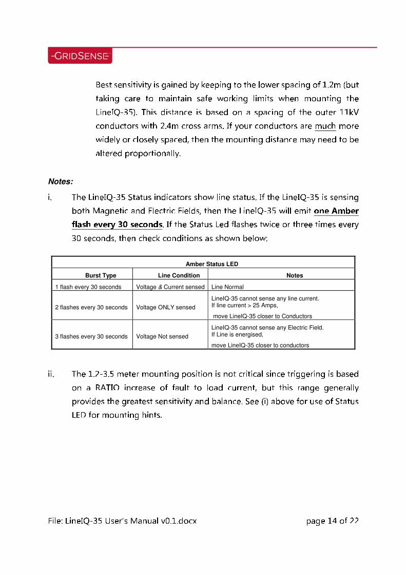
Best sensitivity is gained by keeping to the lower spacing of 1.2m (but taking care to maintain safe working limits when mounting the LineIQ-35). This distance is based on a spacing of the outer 11kV conductors with 2.4m cross arms. If your conductors are much more widely or closely spaced, then the mounting distance may need to be altered proportionally.
Notes: i. The LineIQ-35 Status indicators show line status. If the LineIQ-35 is sensing both Magnetic and Electric Fields, then the LineIQ-35 will emit one Amber flash every 30 seconds. If the Status Led flashes twice or three times every 30 seconds, then check conditions as shown below:
Amber Status LED
Burst Type Line Condition Notes
1 flash every 30 seconds Voltage & Current sensed Line Normal
2 flashes every 30 seconds Voltage ONLY sensed
LineIQ-35 cannot sense any line current. If line current > 25 Amps,
move LineIQ-35 closer to Conductors
3 flashes every 30 seconds Voltage Not sensed
LineIQ-35 cannot sense any Electric Field. If Line is energised,
move LineIQ-35 closer to conductors
ii. The 1.2-3.5 meter mounting position is not critical since triggering is based on a RATIO increase of fault to load current, but this range generally provides the greatest sensitivity and balance. See (i) above for use of Status LED for mounting hints.
File: LineIQ-35 User's Manual v0.1.docx page 15 of 22
4.3.3 For dual circuit locations (e.g. HV with LV conductors beneath), the LineIQ-35 should not be used. The LineIQ-60 should be used with mixed circuits. 4.3.4 Mount the LineIQ-35 on the pole using metal or plastic straps or by drilling and screwing through the mounting plates. 4.3.5 Switch on device by rotating ON/OFF switch on bottom. The LineIQ-35 is disabled until it is switch ON.
4.4 LED’s If the battery is charged the LineIQ-35 will perform a start-up sequence during which the RED LED, AMBER LED will each flash in sequence. If the indicators do not flash the batteries may require recharging. Refer to Section 7 for further details on battery maintenance.
File: LineIQ-35 User's Manual v0.1.docx page 16 of 22
5 Remote Communication

File: LineIQ-35 User's Manual v0.1.docx page 17 of 22
6 Initialization after Startup For the first 60minutes the LineIQ-35 will be in inhibit state. During this time the LineIQ-35 adjusts to the line conditions and automatically adapts to the load profile of the line. However it will not indicate or Log faults until it is commissioned. The LineIQ-35 can be commissioned automatically, (wait 60 minutes) or manually by selecting “Commission (Local) box in the LineMan software.

File: LineIQ-35 User's Manual v0.1.docx page 18 of 22
7 Inrush Restraint The LineIQ-35 will not indicate if the voltage signal has been lost prior to the high current condition. This feature prevents the device from indicating during switch on or reclose events. The device can be configured to override this feature. Further, the LineIQ-35 uses a patented proven algorithm to distinguish between fault currents and inrush currents or load changes. By varying the required trigger threshold due to specific conditions based on voltage signal and long term load the LineIQ-35 will avoid falsely triggering on load changes or inrush events.
File: LineIQ-35 User's Manual v0.1.docx page 19 of 22
8 Troubleshooting 8.1 LINES WITH VOLTAGE REGULATORS A low level fault on the load side of some regulator designs may not trigger the LineIQ-35 on the supply side since the fault current becomes evenly distributed over the three phases on the supply side and may not reach the 100% increase required. When searching for the fault, if an LineIQ-35 on the supply side of the regulator is not indicating, proceed immediately to the fault indicators on the load side of the regulator.
File: LineIQ-35 User's Manual v0.1.docx page 20 of 22
9 Maintenance - Battery Care The LineIQ-35 contains sealed lead-acid rechargeable batteries, which leave our works charged. If the LineIQ-35 is not installed by the `In Service' date shown on the packing box (normally 6 months after dispatch), it must be unpacked and placed outdoors so that the solar panel receives a total of 35 hours direct sunlight to restore charge to the batteries. Or alternatively the LineIQ-35 must be recharged using the LineIQ-Charger (available from GridSense). This will avoid the risk of battery damage due to charge depletion. To maintain the batteries in optimal condition, it is recommended that LineIQ-35’s not in service be charged for at least 48 hours in direct sunlight every 6 months. Refer to section 4.5 for details on testing prior to placing in service. Device should be switched off while recharging. The LineIQ has a design life for the batteries of greater than 7 years when used under normal conditions. LineMan can be used to check the state of charge of the batteries while in service. To check battery voltage left mouse click on the “Status” tab and the displayed data shows the voltage level of the battery. If the batteries are low in capacity (less than 1.85v) after sufficient charging in sunlight, it is recommended that the LineIQ be returned to GridSense for battery replacement.

File: LineIQ-35 User's Manual v0.1.docx page 21 of 22
10 Warranty CHK GridSense Pty Ltd warrants that the LineIQ-35 Network Logger will be free from defects in materials and workmanship under normal use and service for a period of one (1) year from date of receipt. To the maximum extent permitted by applicable law, CHK GridSense Pty Ltd and its suppliers disclaim all other warranties, either express or implied, including, but not limited to, implied warranties of merchantability and fitness for a particular purpose. This limited warranty gives you specific legal rights, you may have others which vary from state/jurisdiction to state/jurisdiction. This unit has been sealed and tested in our factory. Disassembly will void the warranty.

File: LineIQ-35 User's Manual v0.1.docx page 22 of 22
11 LineIQ-35 Network Logger Product Specifications
Overhead System 3 or 2 wire, single earth, SWER
Line Voltage 5 - 145kV
Line Frequency 45 – 65Hz
Fault Current Sensing 5 Amps - 25,000 Amps for Earth Fault
25 Amps - 25,000 Amps for Phase to Phase Fault
Sensing Horizontal and Vertical Magnetic Fields, Electric Field,
Temperature sensor (optional).
Trigger principle
100% increase over prior load "history" with Electric field
variation. Fault type determined by post fault voltage status.
Ratio based discrimination for inrush currents
Fault Sensing Time Two cycle after fault onset (40msec @50Hz)
Memory Size 60KBytes
Power Source Single array of monocrystalline cells, 1W, 3V
Energy Storage 4 x 2V 2.5Ah SLA Cyclon cells.
Battery Life Up to 10 years
Power Consumption
Cellular communications shut down: 10mW (typical)
Cellular communications active: 1W (typical)
Note: Cellular Power consumption varies with signal strength.
Low Battery Indication Yes
Light source Three high intensity LED's, 2 x Red and 1 x Amber
Visibility (daytime / nighttime) 50m/500m
Local Communications 2.4GHz spread spectrum 50m range (line of sight)
Remote Communications Embedded 3G cellular (PCI Express Mini Card). Operates in unsolicited mode with configurable active time window.
Supported Protocols DNP3, FTP, XML.
Operating Temperature Range -20°C to +65°C
(extended -40°C to +85°C upon request)
Humidity 0% to 100%
Materials UV Stable XENOY-X5300WX, Stainless Steel 316,
Silicone Shore A 40.
Dimensions (mm) 265 x 200 x 190
Weight 2.2 kg shipped