132/33kv substation
44
132/33 kv 132/33 kv SUB-STATION SUB-STATION PTCUL PTCUL
-
Upload
akhileshpp -
Category
Documents
-
view
1.223 -
download
307
description
full ppt on substation
Transcript of 132/33kv substation

132/33 kv 132/33 kv SUB-STATIONSUB-STATION
PTCULPTCUL

SUB-STATIONSUB-STATION
ContentContent• Introduction• Single Line Diagram• Transformer• Types of Transformer• Lightning Arrester• Circuit Breaker• Relays• Control Pannel
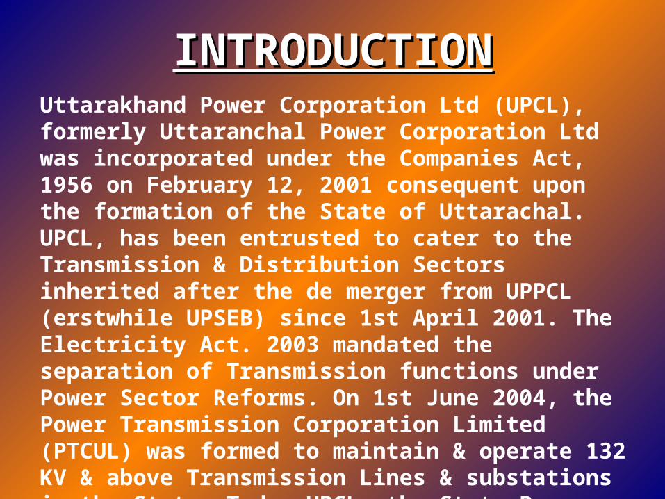
INTRODUCTIONINTRODUCTIONUttarakhand Power Corporation Ltd (UPCL), formerly Uttaranchal Power Corporation Ltd was incorporated under the Companies Act, 1956 on February 12, 2001 consequent upon the formation of the State of Uttarachal. UPCL, has been entrusted to cater to the Transmission & Distribution Sectors inherited after the de merger from UPPCL (erstwhile UPSEB) since 1st April 2001. The Electricity Act. 2003 mandated the separation of Transmission functions under Power Sector Reforms. On 1st June 2004, the Power Transmission Corporation Limited (PTCUL) was formed to maintain & operate 132 KV & above Transmission Lines & substations in the State. Today UPCL, the State Power Distribution Utility of the Government of Uttaranchal (GoU) caters to the Sub –Transmission & Distribution Secondary Substations & Distribution Lines 66 KV & below in the State
UPCL - the Frontline State Power Distribution Utility & service provider of QUALITY & RELIABLE POWER SUPPLY to over 1.59 million consumers of electricity spread over the 13 Districts of Uttarakhand i.e Dehradun, Pauri, Tehri, Haridwar, Pithoragarh, Almora, Nainital, Uttarkashi, Udhamsingh Nagar, Rudraprayag, Chamoli, Bageshwar & Champawat.
The Corporate and Registered Office is at Vidyut bhawan, Near ISBT Crossing, Saharanpur Road, Majra, Dehradun. The Company is managed by the Board of Directors who meet frequently and atleast once in every quarter. The day to day management of the Company is looked after by the Managing Director and other officers of the Company.
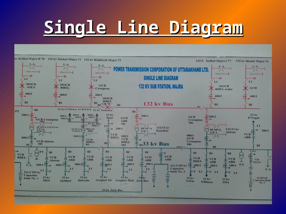
Single Line DiagramSingle Line Diagram

TRANSFORMERTRANSFORMER

• A transformer is a static electrical device that transfers energy by inductive coupling between its winding circuits. A varying current in the primary winding creates a varying magnetic flux in the transformer's core and thus a varying magnetic flux through the secondary winding. This varying magnetic flux induces a varyingelectromotive force (emf) or voltage in the secondary winding.
• Transformers range in size from thumbnail-sized used in microphones to units weighing hundreds of tons interconnecting the power grid. A wide range of transformer designs are used in electronic and electric power applications. Transformers are essential for the transmission, distribution, and utilization of electrical energy.
• The transformer is based on two principles:-• first, that an electric current can produce
a magnetic field• second, that a changing magnetic field
within a coil of wire induces a voltage across the ends of the coil (electromagnetic induction). Changing the current in the primary coil changes the magnetic flux that is developed. The changing magnetic flux induces a voltage in the secondary coil.
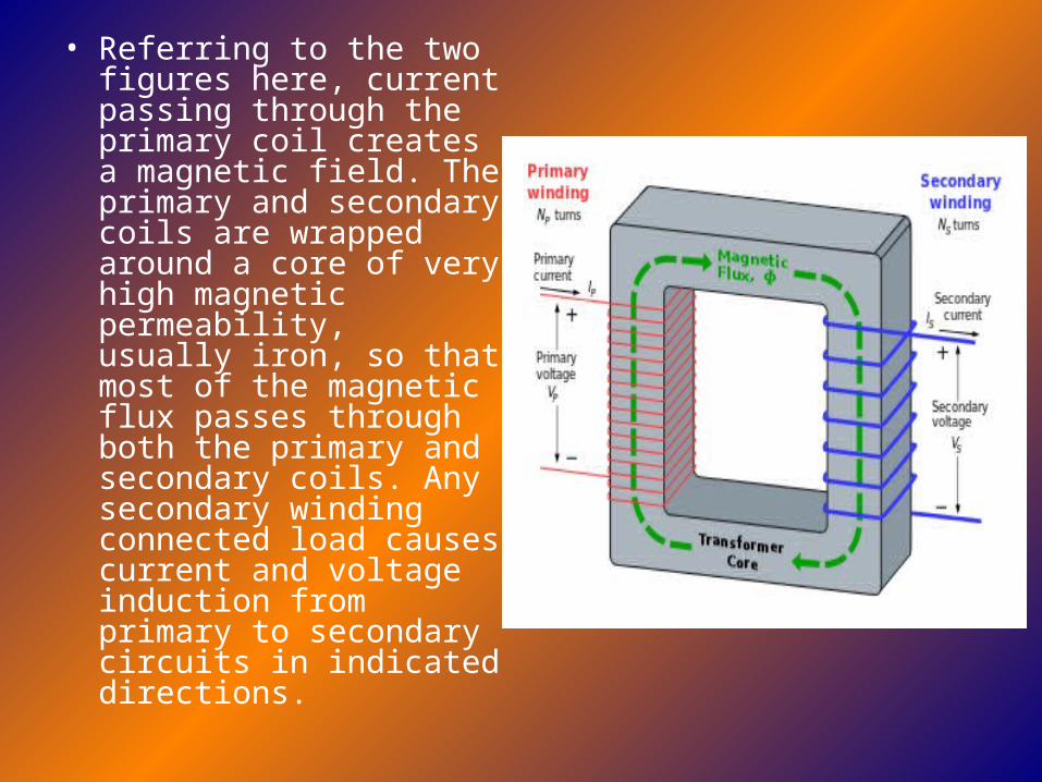
• Referring to the two figures here, current passing through the primary coil creates a magnetic field. The primary and secondary coils are wrapped around a core of very high magnetic permeability, usually iron, so that most of the magnetic flux passes through both the primary and secondary coils. Any secondary winding connected load causes current and voltage induction from primary to secondary circuits in indicated directions.
Types Of Tranformers
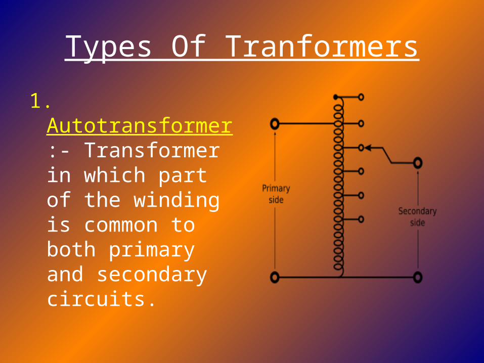
1. Autotransformer :- Transformer in which part of the winding is common to both primary and secondary circuits.
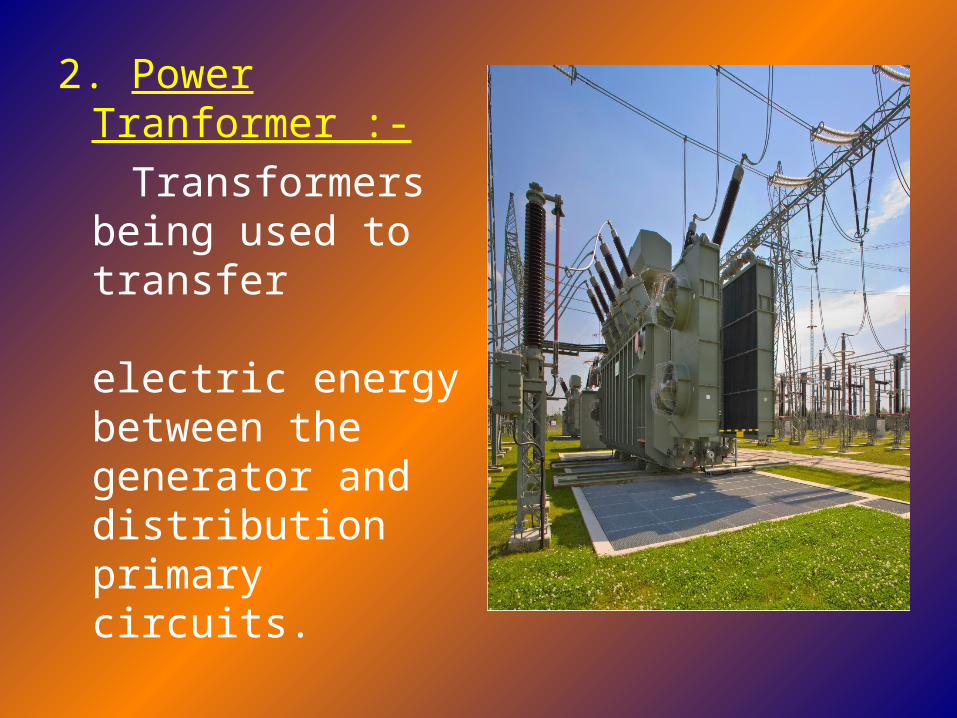
2. Power Tranformer :-
Transformers being used to transfer electric energy between the generator and distribution primary circuits.
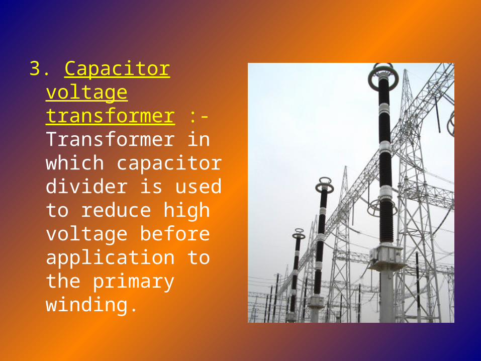
3. Capacitor voltage transformer :-Transformer in which capacitor divider is used to reduce high voltage before application to the primary winding.

4. Instrumental transformer :- Potential or current transformer used to accurately and safely represent voltage, current or phase position of high voltage or high power circuits.
Instrumental Transformer are of two types :-• Current Transformer :- A current transformer (CT) is a series
connected measurement device designed to provide a current in its secondary coil proportional to the current flowing in its primary. Current transformers are commonly used inmetering and protective relays in the electrical power industry.
• Potential Transformer :- Voltage transformers (VT) (also called potential transformers (PT)) are a parallel connected type of instrument transformer, used for metering and protection in high-voltage circuits or phasor phase shift isolation. They are designed to present negligible load to the supply being measured and to have an accurate voltage ratio to enable accurate metering.

5. R.F. Transformer :- Transformers are sometimes made from configurations of transmission line, sometimes bifilar or coaxial cable, wound around ferrite or other types of core. This style of transformer gives an extremely wide bandwidth.
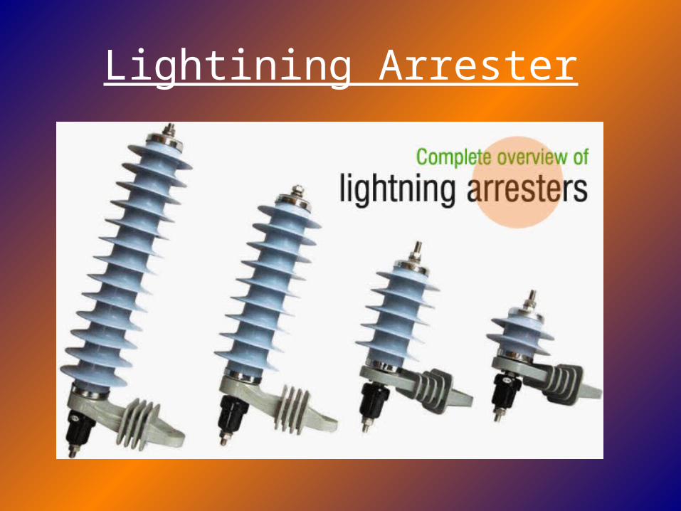
Lightining Arrester

A lightning arrester is a device used on electrical power systems and telecommunications systems to protect the insulation and conductors of the system from the damaging effects of lightning. The typical lightning arrester has a high-voltage terminal and a ground terminal. When a lightning surge (or switching surge, which is very similar) travels along the power line to the arrester, the current from the surge is diverted through the arrestor
Types of Lightning Arrester
• Rod arrester
• Horn gap arrester
• Expulsion type lightning arrester
• Valve type lightning arrester
• Silicon Carbide Arrestors
• Metal Oxide Arrestors

Relays
Basic design
Simple electromechanical relay
Small "cradle" relay

A relay is an electrically operated switch. Many relays use an electromagnet to operate a switching mechanism mechanically, but other operating principles are also used. Relays are used where it is necessary to control a circuit by a low-power signal (with complete electrical isolation between control and controlled circuits), or where several circuits must be controlled by one signal. The first relays were used in long distance telegraph circuits, repeating the signal coming in from one circuit and re-transmitting it to another. Relays were used extensively in telephone exchanges and early computers to perform logical operations.
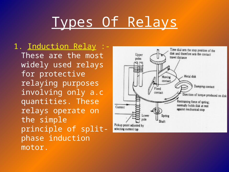
Types Of Relays
1. Induction Relay :- These are the most widely used relays for protective relaying purposes involving only a.c quantities. These relays operate on the simple principle of split-phase induction motor.

2. Thermal Relay :- These relays operate on the principle of thermal effects of electric current.
Mostly used for protection of low voltage suirrel cage induction motor.
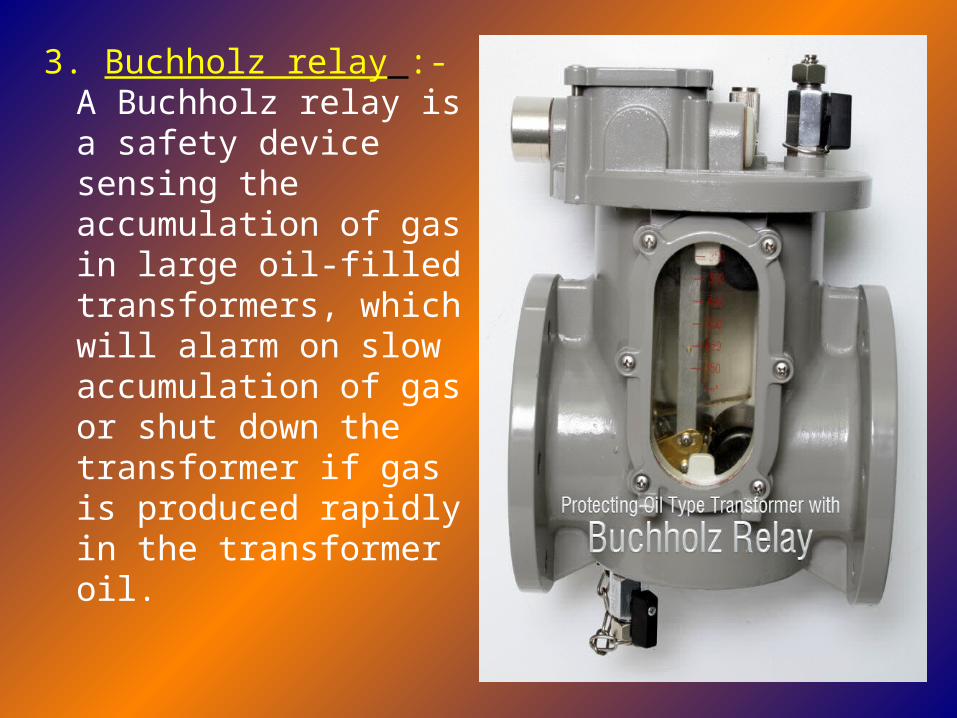
3. Buchholz relay :- A Buchholz relay is a safety device sensing the accumulation of gas in large oil-filled transformers, which will alarm on slow accumulation of gas or shut down the transformer if gas is produced rapidly in the transformer oil.
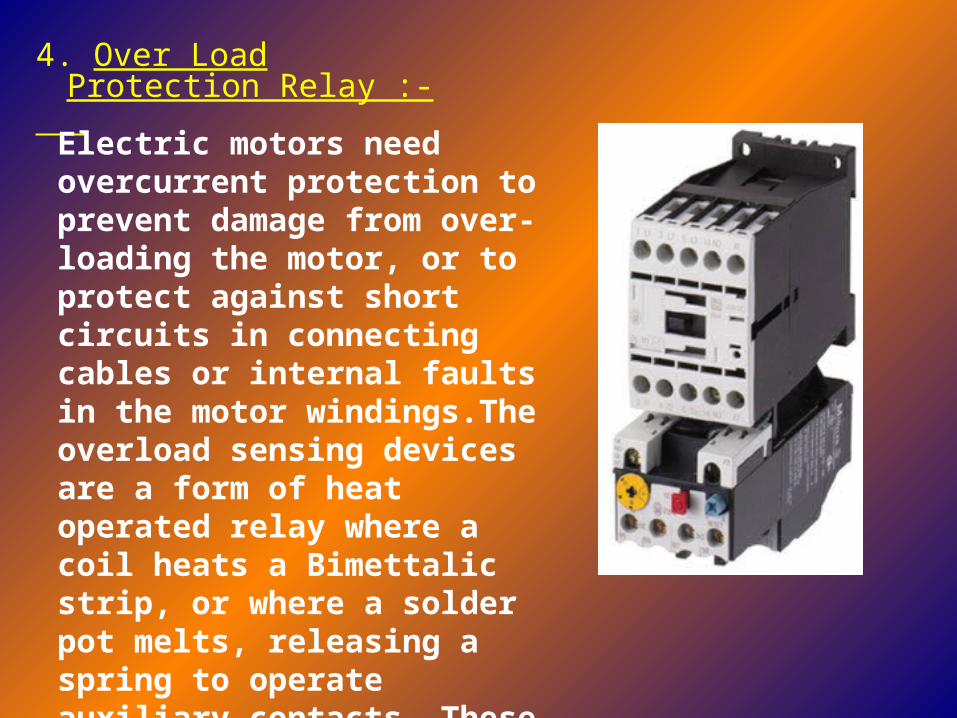
4. Over Load Protection Relay :-
Electric motors need overcurrent protection to prevent damage from over-loading the motor, or to protect against short circuits in connecting cables or internal faults in the motor windings.The overload sensing devices are a form of heat operated relay where a coil heats a Bimettalic strip, or where a solder pot melts, releasing a spring to operate auxiliary contacts. These auxiliary contacts are in series with the coil. If the overload senses excess current in the load, the coil is de-energized.

Other Types of Relays are :-• Latching relay
• Reed relay
• Mercury relay
• Polarized relay
• Ratchet relay
• Coaxial relay

CIRCUIT BREAKERCIRCUIT BREAKER
A circuit breaker is an automatically operated electrical switch designed to protect an electrical circuit from damage caused by overload or short circuit. Its basic function is to detect a fault condition and interrupt current flow. Unlike a fuse, which operates once and then must be replaced, a circuit breaker can be reset (either manually or automatically) to resume normal operation. Circuit breakers are made in varying sizes, from small devices that protect an individual household appliance up to large switchgear designed to protect high-voltage circuits feeding an entire city.

Types of Circuit Breaker
1. Oil Circuit Breaker :-

In an oil circuit breaker with simple interruption under oil, the duration of arcing is 0.02-0.05 sec. To extinguish the arc more efficiently, arc-quenching chambers are used. In a longitudinal blast chamber the vapors and gases evolved travel upward along the arc, thus cooling it. In addition, the arc is in contact with the cold oil that fills the annular slots of the chamber, which also accelerates cooling of the arc. In a transverse blast chamber a drastic pressure increase within the gas bubble causes a stream of oil and gases to flow across the arc, thus accelerating the cooling process.

2. Air Blast Circuit Breaker :-
High pressure air at a pressure between 20 to 30 kg/ cm2 stored in the air reservoir. Air is taken from the compressed air system. Three hollow insulator columns are mounted on the reservoir with valves at their basis. The double arc extinguished chambers are mounted on the top of the hollow insulator chambers. The current carrying parts connect the three arc extinction chambers to each other in series and the pole to the neighbouring equipment. Since there exists a very high voltage between the conductor and the air reservoir, the entire arc extinction chambers assembly is mounted on insulators.
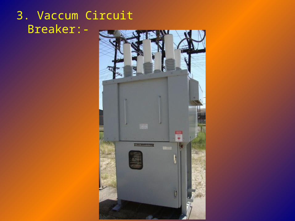
3. Vaccum Circuit Breaker:-

A vacuum circuit breaker is such kind of circuit breaker where the arc quenching takes place in vacuum. The technology is suitable for mainly medium voltage application. For higher voltage Vacuum technology has been developed but not commercially viable. The operation of opening and closing of current carrying contacts and associated arc interruption take place in a vacuum chamber in the breaker which is called vacuum interrupter. The vacuum interrupter consists of a steel arc chamber in the centre symmetrically arranged ceramic insulators.Service life of Vacuum Circuit Breaker is much longer than other types of circuit breakers.
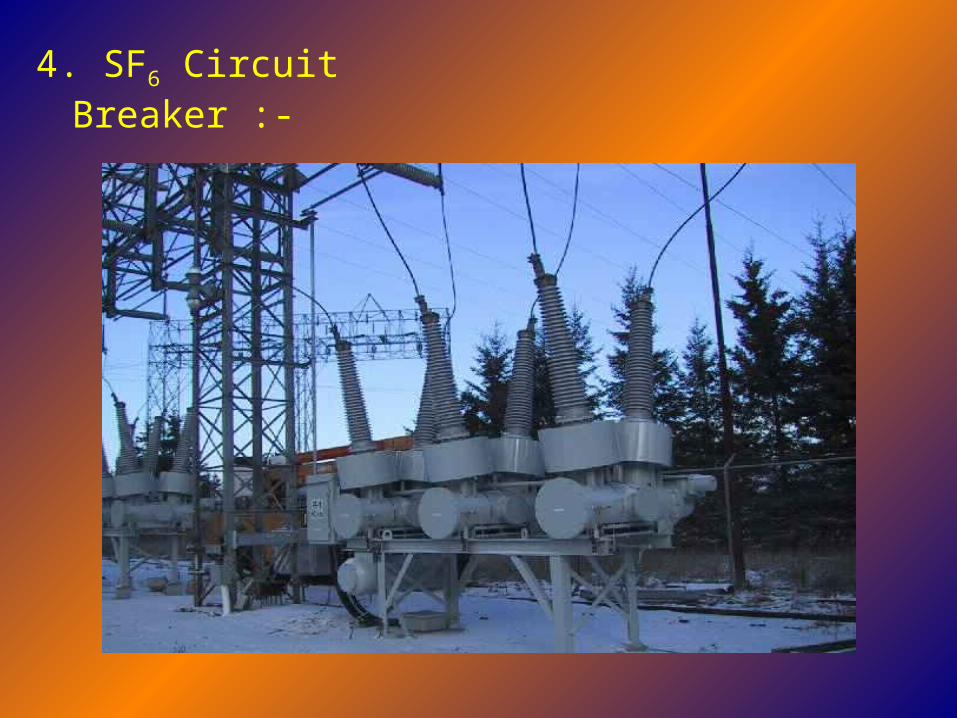
4. SF6 Circuit Breaker :-

A circuit breaker in which the current carrying contacts operate in Sulphur Hexafluoride or SF6 gas is known as an SF6 Circuit Breaker.
SF6 has excellent insulating property. SF6 has high electro-negativity. That means it has high affinity of absorbing free electron. Whenever a free electron collides with the SF6 gas molecule, it is absorbed by that gas molecule and forms a negative ion.
The attachment of electron with SF6 gas molecules may occur in tow different ways,
1) SF6 + e = SF6 -
2) SF6 + e = SF5 - + F
These negative ions obviously much heavier than a free electron and therefore over all mobility of the charged particle in the SF6 gas is much less as compared other common gases. We know that mobility of charged particle is majorly responsible for conducting current through a gas.

CONTROL PANEL

• Control panel is most important equipment of the substation as it work as shield guard for all substation equipments and electrical network. Moreover, these panels are useful to control the flow of electricity as per the Voltage class and detect the faults in transmission lines.
• Designing and manufacturing of Control panel depend on the requirement of utilities and these can broadly be classified as follows;
- Line Protection- Transformer Protection- Bus Bar Protection - Tie Breaker- Bus Coupler - Reactor

• In this panel, varieties of numerical & electromechanical relays are installed to provide damage protection to equipments. Meters, Semaphore indicators, Control Switches, Indicating lamps, Push Buttons, Annunciator, Test Blocks and Test Plugs are among of major equipments installed as per designing requirements.
• The Control & relay panels are designed & manufactured as per voltage class of substations like 11KV, 33KV, 66KV, 132KV, 220KV and 400KV etc. However DC voltage or supply voltage may differ according to the panel requirement such as 30V DC, 110V DC, 220V DC etc. Use of Control & relay panel is not only limited in Substations owned and operated by electrical utilities, but also essential in industrial and commercial sector where power consumption is very high.
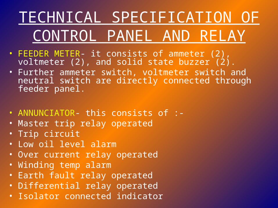
TECHNICAL SPECIFICATION OF CONTROL PANEL AND RELAY
• FEEDER METER- it consists of ammeter (2), voltmeter (2), and solid state buzzer (2).
• Further ammeter switch, voltmeter switch and neutral switch are directly connected through feeder panel.
• ANNUNCIATOR- this consists of :-• Master trip relay operated• Trip circuit• Low oil level alarm• Over current relay operated• Winding temp alarm• Earth fault relay operated• Differential relay operated• Isolator connected indicator

• SWITCH BOARD :- it consists of :-
• Bus coupler: it acts as a intermediate switch board which couple two incoming source generation. A bus coupler is also used in case of fault occurrence. Each time the bus coupler is engaged for the faulty condition of one side of bus bar so as to provide supply to the feeders from the other side. Thus protecting the system.

• INCOMING SUPPLY Rishikesh kulhal Purkul Bindal

• OUTGOING SUPPLY
Ajabpur Niranjanpur Araghar Doiwala I.M.A. Sahastradhara
Fire alarm panel
• In large buildings, a central fire alarm annunciator panel is located where it is accessible to fire-fighting crews. The annunciator panel will indicate the zone and approximate physical location of the source of a fire alarm in the building. The annunciator will also include lamps and audible warning devices to indicate failures of alarm circuits. In a large building such as an office tower or hotel, the fire annunciator may also be associated with a control panel for building ventilation systems, and may also include emergency communication systems for the building.

Thanking you