La te-x3
6
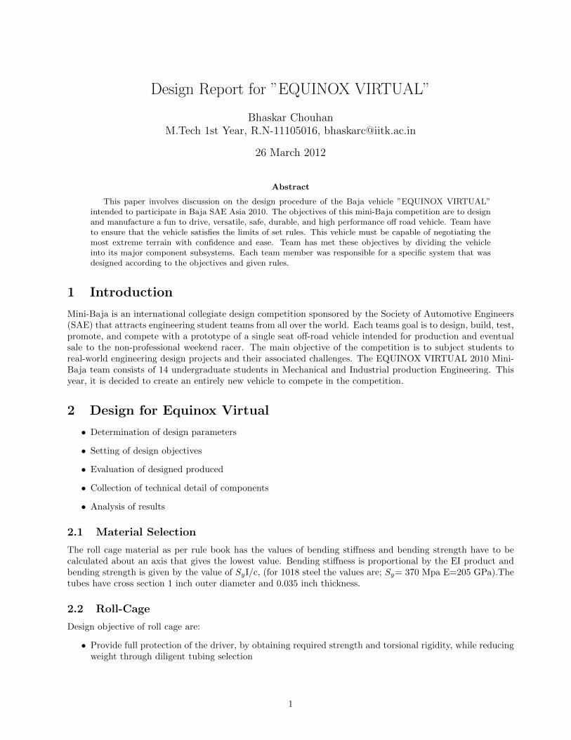
Design Report for ”EQUINOX VIRTUAL” Bhaskar Chouhan M.Tech 1st Year, R.N-11105016, [email protected] 26 March 2012 Abstract This paper involves discussion on the design procedure of the Baja vehicle ”EQUINOX VIRTUAL” intended to participate in Baja SAE Asia 2010. The objectives of this mini-Baja competition are to design and manufacture a fun to drive, versatile, safe, durable, and high performance off road vehicle. Team have to ensure that the vehicle satisfies the limits of set rules. This vehicle must be capable of negotiating the most extreme terrain with confidence and ease. Team has met these objectives by dividing the vehicle into its major component subsystems. Each team member was responsible for a specific system that was designed according to the objectives and given rules. 1 Introduction Mini-Baja is an international collegiate design competition sponsored by the Society of Automotive Engineers (SAE) that attracts engineering student teams from all over the world. Each teams goal is to design, build, test, promote, and compete with a prototype of a single seat off-road vehicle intended for production and eventual sale to the non-professional weekend racer. The main objective of the competition is to subject students to real-world engineering design projects and their associated challenges. The EQUINOX VIRTUAL 2010 Mini- Baja team consists of 14 undergraduate students in Mechanical and Industrial production Engineering. This year, it is decided to create an entirely new vehicle to compete in the competition. 2 Design for Equinox Virtual • Determination of design parameters • Setting of design objectives • Evaluation of designed produced • Collection of technical detail of components • Analysis of results 2.1 Material Selection The roll cage material as per rule book has the values of bending stiffness and bending strength have to be calculated about an axis that gives the lowest value. Bending stiffness is proportional by the EI product and bending strength is given by the value of S y I/c, (for 1018 steel the values are; S y = 370 Mpa E=205 GPa).The tubes have cross section 1 inch outer diameter and 0.035 inch thickness. 2.2 Roll-Cage Design objective of roll cage are: • Provide full protection of the driver, by obtaining required strength and torsional rigidity, while reducing weight through diligent tubing selection 1
-
Upload
asif-hussain -
Category
Business
-
view
330 -
download
0
Transcript of La te-x3
Design Report for ”EQUINOX VIRTUAL”
Bhaskar ChouhanM.Tech 1st Year, R.N-11105016, [email protected]
26 March 2012
Abstract
This paper involves discussion on the design procedure of the Baja vehicle ”EQUINOX VIRTUAL”intended to participate in Baja SAE Asia 2010. The objectives of this mini-Baja competition are to designand manufacture a fun to drive, versatile, safe, durable, and high performance off road vehicle. Team haveto ensure that the vehicle satisfies the limits of set rules. This vehicle must be capable of negotiating themost extreme terrain with confidence and ease. Team has met these objectives by dividing the vehicleinto its major component subsystems. Each team member was responsible for a specific system that wasdesigned according to the objectives and given rules.
1 Introduction
Mini-Baja is an international collegiate design competition sponsored by the Society of Automotive Engineers(SAE) that attracts engineering student teams from all over the world. Each teams goal is to design, build, test,promote, and compete with a prototype of a single seat off-road vehicle intended for production and eventualsale to the non-professional weekend racer. The main objective of the competition is to subject students toreal-world engineering design projects and their associated challenges. The EQUINOX VIRTUAL 2010 Mini-Baja team consists of 14 undergraduate students in Mechanical and Industrial production Engineering. Thisyear, it is decided to create an entirely new vehicle to compete in the competition.
2 Design for Equinox Virtual
• Determination of design parameters
• Setting of design objectives
• Evaluation of designed produced
• Collection of technical detail of components
• Analysis of results
2.1 Material Selection
The roll cage material as per rule book has the values of bending stiffness and bending strength have to becalculated about an axis that gives the lowest value. Bending stiffness is proportional by the EI product andbending strength is given by the value of SyI/c, (for 1018 steel the values are; Sy= 370 Mpa E=205 GPa).Thetubes have cross section 1 inch outer diameter and 0.035 inch thickness.
2.2 Roll-Cage
Design objective of roll cage are:
• Provide full protection of the driver, by obtaining required strength and torsional rigidity, while reducingweight through diligent tubing selection
1
• Design for manufacturability, as well as cost reduction, to ensure both material and manufacturing costsare competitive with other SAE vehicles
• Improve driver comfort by providing more lateral space and leg room in the driver compartment
• Maintain ease of serviceability by ensuring that roll cage members do not interfere with other subsystems
2.3 Main Element of the Rollcage
• Rear Roll Hoop (RRH)
• Roll Hoop Overhead Members (RHO)
• Front Bracing Members (FBM)
• Lateral Cross Member (LC)
• Side impact members(SIM)
• Lateral Diagonal Bracing (LBD)
• Lower Frame Side (LFS)
• Front Lateral Cross Member (FLC)
2.4 Modelling Process of Rollcage
2.4.1 Design
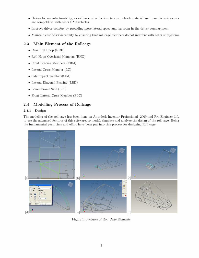
The modeling of the roll cage has been done on Autodesk Inventor Professional -2009 and Pro-Engineer 3.0,to use the advanced features of this software, to model, simulate and analyze the design of the roll cage. Beingthe fundamental part, time and effort have been put into this process for designing Roll cage.
[a] [b] [c]
[d] [e] [f]
Figure 1: Pictures of Roll Cage Elements
2
2.4.2 RRH and SF
• The driver’s seat may not intrude into the plane(s) of the RRH. The upper junctions in straight-tubeconstruction shall define points BR and BL. If bent-tube construction is used, points BR and BL willoccur at the upper end of each bend. The RRH (figure 1-a) shall extend upward vertically ±20 degreesfrom points A to points B. The RRH must also be a minimum of 73.6 cm (29 in) wide at 68.6 cm (27in)above the driver’s seat
• SF frame is set at an angle of 45deg and the width is 10 inches so that A arms can be mounted at 8.5inches (vertical distance).
2.4.3 Extended Hitch Frame
It ( Figure 1-c) is provided in order:
• to give better aesthetic looks
• to meet the constraint of FBM (figure 1-d)of ≤ 45 deg
• to meet the constraint of Side Impact members (SIM) of 8-14 inches from seat base.
2.4.4 SIM
• SIM (figure 1-e) is made wider at the drivers end and is kept this time in a single plane so in order toreduce the get out time of the driver from the cockpit and as per driver comfort during gear changingand vehicle riding.
2.5 Modelling of Steering on ADAMS VIEW
We are proposing two steering models
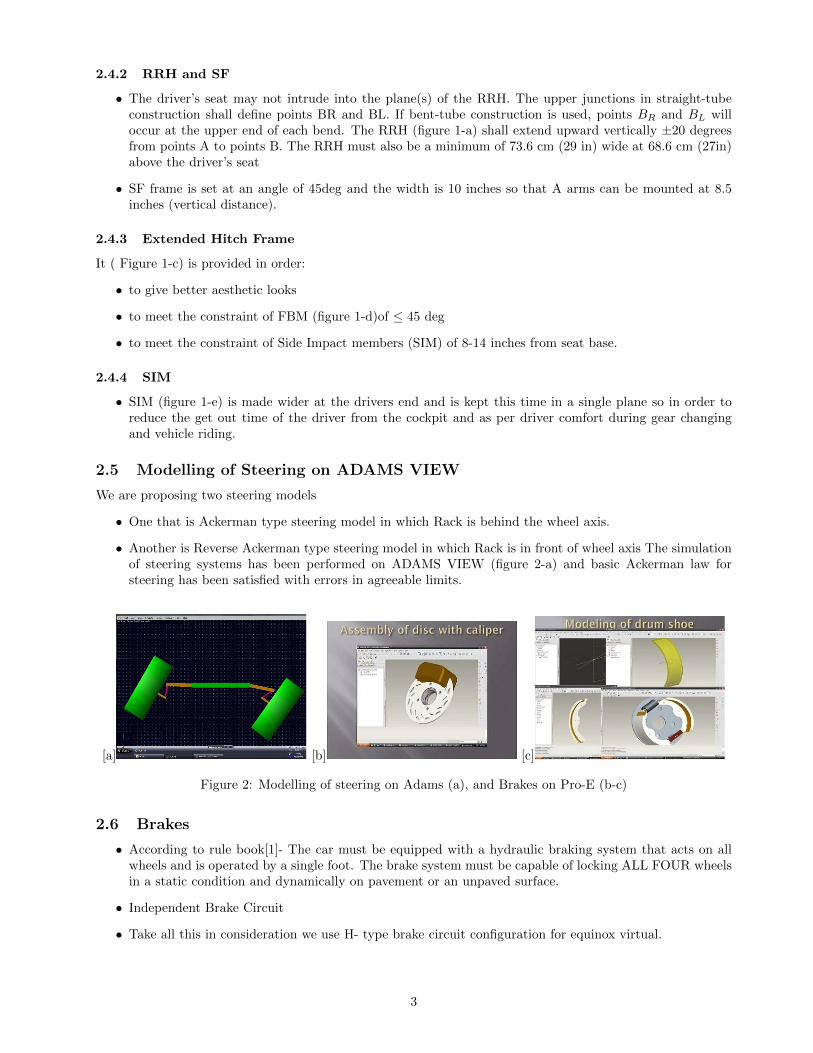
• One that is Ackerman type steering model in which Rack is behind the wheel axis.
• Another is Reverse Ackerman type steering model in which Rack is in front of wheel axis The simulationof steering systems has been performed on ADAMS VIEW (figure 2-a) and basic Ackerman law forsteering has been satisfied with errors in agreeable limits.
[a] [b] [c]
Figure 2: Modelling of steering on Adams (a), and Brakes on Pro-E (b-c)
2.6 Brakes
• According to rule book[1]- The car must be equipped with a hydraulic braking system that acts on allwheels and is operated by a single foot. The brake system must be capable of locking ALL FOUR wheelsin a static condition and dynamically on pavement or an unpaved surface.
• Independent Brake Circuit
• Take all this in consideration we use H- type brake circuit configuration for equinox virtual.
3
2.6.1 Type of brake use for Equinox Virtural
Hydraulically operated
• Disc brake in front tires (figure 2-b)
• Drum brake in rear tires (figure 2-c)
2.7 Power Train
To utilize the full power output of the 338cc lombardini LGA-340, 8 kW petrol engine, a four speed transmissionwith a reverse, is designed to provide a low and high gear range. With the cockpit mounted shift lever in lowgear, the driver has the torque available for towing heavy loads, climbing steep gradients, and driving throughmud and loose sand. The high gear is designed for top speed and acceleration.
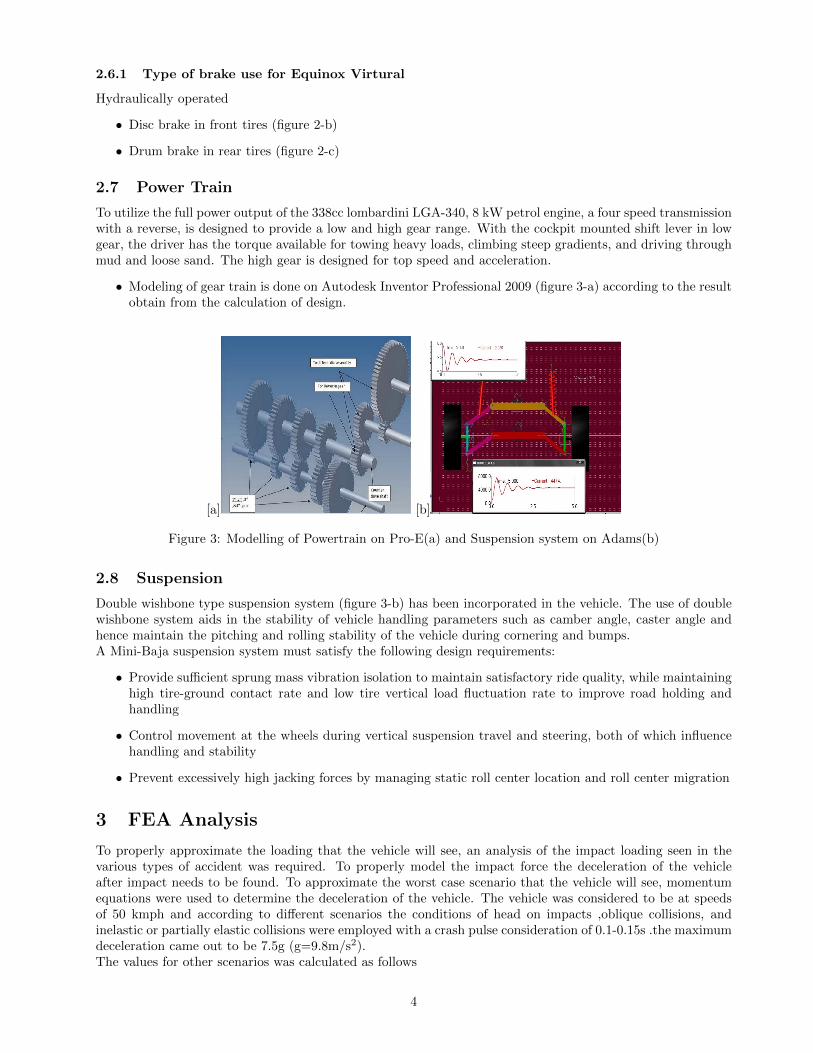
• Modeling of gear train is done on Autodesk Inventor Professional 2009 (figure 3-a) according to the resultobtain from the calculation of design.
[a] [b]
Figure 3: Modelling of Powertrain on Pro-E(a) and Suspension system on Adams(b)
2.8 Suspension
Double wishbone type suspension system (figure 3-b) has been incorporated in the vehicle. The use of doublewishbone system aids in the stability of vehicle handling parameters such as camber angle, caster angle andhence maintain the pitching and rolling stability of the vehicle during cornering and bumps.A Mini-Baja suspension system must satisfy the following design requirements:
• Provide sufficient sprung mass vibration isolation to maintain satisfactory ride quality, while maintaininghigh tire-ground contact rate and low tire vertical load fluctuation rate to improve road holding andhandling
• Control movement at the wheels during vertical suspension travel and steering, both of which influencehandling and stability
• Prevent excessively high jacking forces by managing static roll center location and roll center migration
3 FEA Analysis
To properly approximate the loading that the vehicle will see, an analysis of the impact loading seen in thevarious types of accident was required. To properly model the impact force the deceleration of the vehicleafter impact needs to be found. To approximate the worst case scenario that the vehicle will see, momentumequations were used to determine the deceleration of the vehicle. The vehicle was considered to be at speedsof 50 kmph and according to different scenarios the conditions of head on impacts ,oblique collisions, andinelastic or partially elastic collisions were employed with a crash pulse consideration of 0.1-0.15s .the maximumdeceleration came out to be 7.5g (g=9.8m/s2).The values for other scenarios was calculated as follows
4

• As a side impact is most likely to occur with the vehicle being hit by another the Baja vehicle, it wasassumed that neither vehicle would be a fixed object. Referring to automotive industry safety test, whichalso makes the equivalent assumption, the impact force was assumed to be half that of head on collisionwith a fixed object or a deceleration of 3.75g’s.
• Due to the damping effects of the shock absorbers in the suspension, the forces seen on the shock mountswere also assumes to be 3.5g’s. This value is an extreme overestimation, but will allow the ability toaccount for a blown shock absorber.
• As the impact on the roll cage in a roll over is most often a secondary impact or a glancing blow, it wasassumed that the roll cage would see a deceleration of approximately 2.5 g’s.
• In all the above cases the transient analysis approach was taken to generalize the problem and account forthe time variant behavior of impact load application .the time of crash pulse was divided into 100 stepseach comprising of 1ms .The results arrived are shown in figures below and explained in next section.
[a] [b] [c]
[d] [e]
Figure 4: FEA Analysis
3.1 Stress Analysis
• Front Collision (figure 4-a) -Higher values of stresses were indicated at the SIM and suggested improve-ment in the truss provided, the initial values of stresses in the tube section were 237 MPa which exceededthe permissible value of 200 MPa (FOS=1.8). Hence truss modification was done. After truss modificationthe stress value has been lowered to 185 MPa which is under the permissible value.
• After truss modification on SIM member (figure 4-b)
Max stress in the section 237 MpaAfter truss modification 185 Mpa
• Deformation Analysis(figure 4-c)
• Roll Over Impact (figure 4-d)
• Deflection (figure 4-e)
5
4 Technical Specification of EQUINOX VIRTUAL
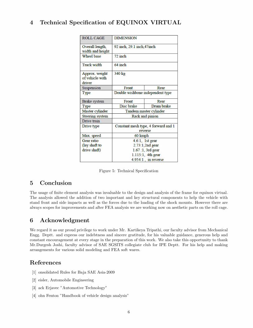
Figure 5: Technical Specification
5 Conclusion
The usage of finite element analysis was invaluable to the design and analysis of the frame for equinox virtual.The analysis allowed the addition of two important and key structural components to help the vehicle withstand front and side impacts as well as the forces due to the loading of the shock mounts. However there arealways scopes for improvements and after FEA analysis we are working now on aesthetic parts on the roll cage.
6 Acknowledgment
We regard it as our proud privilege to work under Mr. Kartikeya Tripathi, our faculty advisor from MechanicalEngg. Deptt. and express our indebtness and sincere gratitude, for his valuable guidance, generous help andconstant encouragement at every stage in the preparation of this work. We also take this opportunity to thankMr.Durgesh Joshi, faculty advisor of SAE SGSITS collegiate club for IPE Deptt. For his help and makingarrangements for various solid modeling and FEA soft wares.
References
[1] onsolidated Rules for Baja SAE Asia-2009
[2] eisler, Automobile Engineering
[3] ack Erjavec ”Automotive Technology”
[4] ohn Fenton ”Handbook of vehicle design analysis”
6