Keyence Programming
392
User's Manual Visual KV Series 3 Programming 96M0366 How this manual is organized: The Visual KV Series User’s Manual is composed of 3 separate manuals; 1-Installation, 2-Support Software, 3-Programming. Please read each manual relevant to your purpose.
description
pROGRAMACION
Transcript of Keyence Programming
7/18/2019 Keyence Programming
http://slidepdf.com/reader/full/keyence-programming 1/392
User's Manual
Visual KV Series
3
Programming
96M0366
How this manual is organized:
The Visual KV Series User’s Manual is composed of 3 separatemanuals; 1-Installation, 2-Support Software, 3-Programming.
Please read each manual relevant to your purpose.

7/18/2019 Keyence Programming
http://slidepdf.com/reader/full/keyence-programming 2/392
Safety Precautions
This instruction manual describes the operation and function of th
Read this manual carefully to ensure safe use and maximum perKV Series PLC.
Symbols
The following symbols alert you to important messages. Be sure messages carefully.
Failure to follow instructions may lead to inshock, burn, etc.)
Failure to follow instructions may lead to p
Provides additional information on proper
Conventions
This manual describes the operation/function of all Keyence KV SNote following conventions when you use.
General Precautions
• At startup and during operation, be sure to monitor the functiomance of the KV Sereis PLC.
• We recommend that you take substantial safety measures to in the event a problem occurs.
• Do not open or modify the KV Series PLC or use it in any wayscribed in the specifications.
Wh th KV S i PLC i d i bi ti ith th i
WARNING
CAUTION
Note:
Visual KV (Series) KV-10AR/AT/DR/DT KV-16AR/AT/DKV-10xx, 16xx, 24xx, 40xx KV-24AR/AT/DR/DT KV-40AR/AT/D
Conventional KV (Series) KV-10R(W)/T(W) KV-16R(W)/T(
KV-300 (Series) KV-24R(W)/T(W) KV-40R(W)/T(KV-10/80 (Series) KV-80R(W)/T(W)KV-300
7/18/2019 Keyence Programming
http://slidepdf.com/reader/full/keyence-programming 3/392
Note to User
When using the Visual KV Series in the following cond
sure to use the Visual KV Series with sufficient marginfunctions, take appropriate safety precautions such assales personnel if any questions arise.
• Use in conditions or environments not described in
• Use for nuclear power control, railway facilities, aircombustion devices, medical equipment, amusemement, etc.
• Use for applications where large effects are predicand properties and safety is especially requested.
Restriction on Acquiring the CE Marking
Restriction to be compatible with EMC directive
• When using a relay output type unit (whose modelspark killers having the appropriate withstand voltaoutput terminals in parallel to contacts (because th
contact becomes open and noise is generated). In following models of spark killers.
XEB0101 0.1 µF-10 Ω manufactured by OKAYA D
The following 1-turn ferrite core is added to the AC40AR/T, the KV-24AR/T and to the DC power inpu
ZCAT3035-1330 manufactured by TDK
Note: The contents above do not by themselves ensumanufactured in accordance with the above contents directives.
You must judge by yourself whether or not the entire mEMC directives because compatibility may change deconfiguration, wiring and location inside of the machin
Restriction on compatibility with low-voltage d
• Use insulated type crimp-style terminals.
• For wiring materials, use lead wires whose sheath
• The Visual KV Series is allowed to be installed in a(Spacers for expansion units are not available.)
• Be sure to use the Visual KV Series inside the con
7/18/2019 Keyence Programming
http://slidepdf.com/reader/full/keyence-programming 4/392
Features of the Visual KV Series
Extremely small
The Visual KV Series is the smallest in the world among AC twith screw terminal blocks, and saves installation space.
Extremely fast
The minimum scan time is 140 µs and minimum instruction exµs, which is the fastest control in its class.
AC power built-in type newly added
AC power built-in type units are newly added. This type can bspaces where a switching power supply unit cannot be installe
Excellent Access Window
An Access Window with two-color backlight is adopted in all mchanging and monitoring of device data. Changing between RPROGRAM mode, checking the error code when an error hasbe performed in a Visual KV Series unit without the need for aprogrammer.
The analog trimmer, which has been popular in the conventiodigitized to enable more detail settings. [Digital trimmers]
User message setting function
In the Access Window, 256 different user messages can be dfunction can be used to give instructions on works on the prodabnormalities in the units, etc.
Program write in RUN modeLadder programs can be changed even while the system is ru
Equipped with two serial ports
Visual KV Series basic units are equipped with two serial porteral units, improving the debug environment.(The KV-10xx is equipped with only one serial port.)
Easy Ramp-up/down control function
The one-axis motor control function is offered separately fromcounters so that feedback control is enabled.
Equipped with two 24-bit high-speed 30 kHz, two-phase c
The Visual KV Series is equipped with two high-speed countepoint comparator output function that enables high speed enc

7/18/2019 Keyence Programming
http://slidepdf.com/reader/full/keyence-programming 5/392
Interrupt function
The Visual KV Series is equipped with four high-sp10 µs maximum.
Input time constant change function
The time constant can be set in 7 steps from 10 µs
Double memory backup functions
In addition to a conventional SRAM battery backupis also equipped with an EEPROM backup function
Compatibility with Conventional KV Series PThe Visual KV Series functions as a high-end compatKV Series. Peripheral units of the conventional KV Sesoftware "KV IncrediWare (DOS)" and "LADDER BUILhandheld programmer KV-P3E(01) can be used sinceSeries.However, it should be noted that the contents have ch
• The internal clock cycle of high-speed counters coµs, and 100 µs.
• The time constant for an input relay specified by th
• The analog trimmer function is set with the Accessunit.
• The available device setting range of the TMIN ins[Handheld programmer KV-P3E(01) can display 0
• The RUN/PROGRAM LED is displayed in the Accefront face of the basic unit.
• Transistor output is not independent, but is commo
• With the transistor type, the output terminal layout
• The specifications for output current of transistor omA.
• Conventional KV Series expansion units are not avthe Visual KV Series.
• The channel setting switch is not provided for expdetermined in connection order.
• Scans in expansion I/O units are not synchronous Series basic units.
• Assignment of special utility relays has partially ch

7/18/2019 Keyence Programming
http://slidepdf.com/reader/full/keyence-programming 6/392
Cautions when using the previous version of ladder support s
Pay strict attention to the following items when using the ladder s
• When using the ladder support software "KV IncrediWare (DOBUILDER for KV Ver. 1.0x", set the model to "KV-300".
• DM0 to DM1999 are only available.
When the ladder support software "LADDER BUILDER for Kused, do not use the monitor’s Change All function. If the Chis used, the basic unit may be damaged. Never use the Chan
Peripheral units and other units incompatible with the Visual K
Peripheral units in the conventional KV Series and other units shcompatible with the Visual KV Series.
• Expansion I/O units for the conventional KV Series: KV-8ER/88EYR/8EYT/16EYR/16EYT
• Analog I/O units for the conventional KV Series: KV-AD4/DA4
Cautions when Using the Serial PortThe KV-16xx/24xx/40xx units are equipped with two RJ-11 moduserial communication.When using them, pay strict attention to the following contents:
• Programs can be transferred and monitored using either comB. However, never connect the ladder software and a handhethe two ports at the same time.
• The KV-D20 operator interface panel can be connected to eitport A or B. However, only one KV-D20 unit can be connectedunit.
• Never leave both the KV-D20 operator interface panel and KVprogrammer on simultaneously for a long period of time.
CAUTION

7/18/2019 Keyence Programming
http://slidepdf.com/reader/full/keyence-programming 7/392

7/18/2019 Keyence Programming
http://slidepdf.com/reader/full/keyence-programming 8/392
How this manual is organized
The Visual KV Series User’s Manual is composed of 3 sepa
1-Installation, 2-Support Software, 3-Programming. Please rrelevant to your purpose.
1 Installation
Chapter 1 Configuration and Specifications [Visual KV Series
Describes the system configuration of the Visual KV Series, the naeach part, and the specifications.
Chapter 2 System Installation [Visual KV Series Only]
Describes the installation and connection of each Visual KV Seriessystem maintenance.
Chapter 3 Access Window [Visual KV Series Only]
Describes the Access Window used for changing and monitoring d
Chapter 4 KV-D20 Operator Interface Panel [Visual KV Series
Describes the KV-D20 Operator Interface Panel used for changingdisplaying the status of inside relays, timers, counters and data me
Chapter 5 KV-300, KV-10/80 Hardware [KV-300, KV-10/80 Serie
Describes the hardware specifications and wirings for KV-300 and
Chapter 6 Handheld Programmer
Describes how to use the handheld programmer and memory card
Chapter 7 KV-L2 Serial Interface Module [KV-300 Series Only]
Describes the serial interface modules for KV-300 Series.
Chapter 8 KV-AN6 Analog I/O Module [KV-300 Series Only]
Describes the optional Analog I/O module for KV-300 Series
Chapter 9 KV-AD4/DA4 Analog I/O Unit [KV-10/80 Series Only
Describes the optional Analog I/O unit for KV 10/80 Series

7/18/2019 Keyence Programming
http://slidepdf.com/reader/full/keyence-programming 9/392
Chapter 2 Editor
Describes the operating procedures in Editor mode.
Chapter 3 Simulator
Describes the operating procedures in Simulator mode
Chapter 4 Monitor
Describes the operating procedures in Monitor mode.
Appendices
Includes instructions list, devices list, sample program operation and shortcuts.
3 Programming
Chapter 1 Programming
Describes basic knowledge including program creationrelay assignments, special functions to set and confirmwell as the extended ladder diagrams. Understand the
pletely at first before creating programs.
Chapter 2 Instructions
Describes the concrete usage of instructions in the KV Refer to "Chapter 3 Interrupts" on page 3-183 for detaiRefer to "Chapter 4 High-speed counters" on page 3-1counters used in the application instruction.
Chapter 3 Interrupts [Visual KV Series Only]
The interrupt processing function executes an interruptor request from the high-speed counter comparator (intduring KV operation.This chapter describes the types of interrupt factors as encountered during interrupt processing.
Chapter 4 High-speed Counters [Visual KV Series O
Describes high-speed counters and high-speed countespeed pulse measurement and pulse output, independ
Chapter 5 Positioning Control [Visual KV Series Onl
Describes ramp-up/down control of stepping motors an
7/18/2019 Keyence Programming
http://slidepdf.com/reader/full/keyence-programming 10/392
Contents
3 Programming
Chapter 1 Programming
1.1 Before Creating Programs .....................................................
1.1.1 Flow from Introduction to Operation ..........................................1.1.2 Scan Time..................................................................................
Scan time ............................................................................Input response time delay ...................................................
1.2 User Memory ...........................................................................
1.2.1 Program Capacity ......................................................................Maximum number of lines in a program..............................Calculating the byte count used ..........................................
1.3 Device Configuration ..............................................................
1.3.1 Device List .................................................................................Relay list .............................................................................List of I/O relays in basic units ............................................List of relays in expansion units ..........................................
1.3.2 Relay No. ...................................................................................
Address No. ........................................................................Contact No. .........................................................................Channel No. ........................................................................
1.3.3 Assigning Relay Nos..................................................................1.3.4 Input Relays ...............................................................................
Basic unit ............................................................................Expansion unit ....................................................................
1.3.5 Output Relays ............................................................................Output operation time .........................................................
1.3.6 Internal Utility Relays .................................................................
Retentive function of internal utility relays...........................1.3.7 Special Utility Relays .................................................................
Description ..........................................................................1.3.8 Special Utility Relay List ............................................................
Special relays and arithmetic operation flags .....................Special utility relays for high-speed counter(0) ...................Special utility relays for high-speed counter(1) ...................Other special utility relays ...................................................
1.3.9 Timers and Counters .................................................................Timer/Counter list ................................................................
Description ..........................................................................1.3.10 Data Memories ..........................................................................1.3.11 Temporary Data Memory ...........................................................1.3.12 Relay Nos. and Functions ..........................................................
1.4 Special Functions ...................................................................
1.4.1 Input Time Constant Change Function ......................................S tti th i t ti t t f b i it i i

7/18/2019 Keyence Programming
http://slidepdf.com/reader/full/keyence-programming 11/392
Chapter 2 Instructions
2.1 Instruction List [Visual KV Series] ....................
2.1.1 Basic Instructions ....................................................2.1.2 Application Instructions ...........................................2.1.3 Arithmetic Instructions ............................................2.1.4 Interrupt Instructions ...............................................2.1.5 Function No. List (Alphabetical order) ....................
2.2 Instruction List [KV-300 Series, KV-10/80] .......
2.2.1 Basic Instructions ....................................................2.2.2 Application Instructions ...........................................2.2.3 Arithmetic Instructions ............................................2.2.4 Interrupt Instructions ...............................................
2.3 Convention Details ..............................................
2.4 Instruction Details ................................................
2.4.1 Basic Instructions ....................................................2.4.2 Application Instructions ...........................................2.4.3 Arithmetic Instructions ............................................
2.5 Programming Notes .............................................
Chapter 3 Interrupts
3.1 Interrupt Instructions ...........................................
3.2 Interrupt Processing ............................................
3.2.1 Interrupt Processing................................................3.2.2 Types of Interrupts ..................................................3.2.3 Interrupt Priority ......................................................3.2.4 Interrupt Program....................................................
3.3 Direct Input/Output ..............................................
3.3.1 Direct Input .............................................................
3.3.2 Direct Output...........................................................3.4 Applications of Interrupt Programs ...................
3.4.1 Interrupt with a Signal Converter ............................3.4.2 Interrupt with a High-speed Counter .......................3.4.3 Measuring the ON Time of High-speed Pulses ......3.4.4 Measuring the Period in which a Target Passes bet
Chapter 4 High-speed Counters
4.1 High-speed Counter Instructions .......................4.2 Outline of High-speed Counters .........................
4.2.1 High-speed Counters and High-speed Counter ComStructure of high-speed counters and high-speSpecifications of high-speed counters .............High-speed counter comparators .....................
4 2 2 Internal Clock for High-speed Counters

7/18/2019 Keyence Programming
http://slidepdf.com/reader/full/keyence-programming 12/392
4.5.1 Specified Frequency Pulse Output Function .............................4.5.2 Applications of the Specified Frequency Pulse Output ..............4.5.3 Frequency Counter Function .....................................................4.5.4 Applications of Frequency Counters ..........................................
4.5.5 Cam Switch Function .................................................................Cam switch mode ...............................................................Multi-step comparator mode ...............................................Setting method ....................................................................
4.5.6 Application of the Cam Switch (Cam Switch Mode) ..................
4.6 Direct Clock Pulse Output ......................................................
4.6.1 Outline of Direct Clock Pulse Output .........................................4.6.2 Pulse Output Setting with the High-speed Counter Comparator
Changing the pulse period and width...................................
Calculating the pulse period and comparator preset value .Operation with special utility relays .....................................
4.7 Examples of Direct Clock Pulse Output ...............................
4.7.1 Example of Outputting a Pulse with 1:1 ON/OFF Ratio .............4.7.2 Example of Outputting a Pulse with Variable ON/OFF Ratio .....4.7.3 Example of Stopping the Pulse Output at a Specified Pulse Cou4.7.4 Application of Direct Clock Pulse Output (Ramp-up/down contro
Chapter 5 Positioning Control
5.1 Outline of Positioning Control ...............................................
5.1.1 Ramp-up/down Control ..............................................................
5.2 Parameter Setting and Operating Procedures .....................
5.2.1 Parameter Setting Procedure ....................................................5.2.2 Operating Procedure .................................................................
5.3 Examples of Using the Positioning Control Function .........
5.3.1 Connection Example ..................................................................5.3.2 Tips ............................................................................................
5.3.3 Application Examples of the Positioning Control Function ........
Chapter 6 Interrupts, High-speed Counters,
Positioning Control KV-30
6.1 Interrupt Instructions ..............................................................
6.1.1 Description of Interrupts.............................................................Input processing for routine program and interrupt routine .Types of interrupt ................................................................
Interrupt priority ...................................................................Interrupt routine ...................................................................Direct output ........................................................................Direct input ..........................................................................
6.1.2 Interrupt Instructions ..................................................................
6.2 Direct Clock Pulse ...................................................................
6.2.1 Output of Direct Clock Pulse......................................................
7/18/2019 Keyence Programming
http://slidepdf.com/reader/full/keyence-programming 13/392
7.2.2 Format of Commands/Responses ..........................7.2.3 Communication Command/Response List .............7.2.4 Setting Communication Commands and Response7.2.5 Other Response Codes ..........................................
7.2.6 Error Code List........................................................7.2.7 Example Program ...................................................
7.3 Loading Text Data ................................................
7.3.1 Receiving Text Data ...............................................7.3.2 Transmitting Text Data ...........................................7.3.3 Sample Program .....................................................
7.4 ASCII Code List ....................................................
Chapter 8 Programming Examples
8.1 List .................................................................
8.2 Details .................................................................
8.2.1 Reference Program Examples................................Basic Instructions .............................................Application Instructions ....................................Arithmetic Instructions......................................
WARRANTIES AND DISCLAIMERS
1 Installation
Chapter 1 Configuration and Specifications
1.1 System Configuration ..........................................
1.1.1 System Configuration .............................................
1.2 Specifications .......................................................
1.2.1 General Specifications ............................................1.2.2 AC Power Specifications ........................................Visual KV Series operation at power interruptio
1.2.3 Performance Specifications ....................................Data backup function against instantaneous po
1.3 Common I/O Specifications of Basic Units .......
1.3.1 Model of a Basic Unit ..............................................1.3.2 Common I/O Specifications ....................................
1.4 KV-10AR/AT(P)/DR/DT(P) (10-I/O Basic Unit) ...
1.4.1 Part Names and Functions .....................................1.4.2 Terminal Layout Drawings and I/O Circuit Diagram
KV-10AR/DR (Relay output type) ....................KV-10AT(P)/DT(P) (Transistor output type) .....
1.4.3 AC Power Input (KV-10AR/AT(P)) ..........................1.4.4 Relationship between Continuous Simultaneous ON Rati1.4.5 Dimensions .............................................................
7/18/2019 Keyence Programming
http://slidepdf.com/reader/full/keyence-programming 14/392
1.7.1 Part Names and Functions ........................................................1.7.2 Terminal Layout Drawings and I/O Circuit Diagrams.................
KV-40AR/DR (Relay output type) .......................................KV-40AT(P)/DT(P) (Transistor output type) ........................
1.7.3 AC Power Input (KV-40AR/AT(P)) .............................................1.7.4 Relationship between Continuous Simultaneous ON Ratio and Ambien1.7.5 Dimensions ................................................................................
1.8 KV-E4X/E8X/E16X (Expansion Input Unit) ...........................
1.8.1 Part Names and Functions ........................................................1.8.2 Input Specifications....................................................................1.8.3 Terminal Layout Drawings and Input Circuit Diagrams .............
KV-E4X (4-I/O expansion input unit) ...................................KV-E8X (8-I/O expansion input unit) ...................................
KV-E16X (16-I/O expansion input unit) ...............................1.8.4 Dimensions ................................................................................
1.9 KV-E4R/E4T/E8R/E8T(P)/E16R/E16T(P) (Expansion Output
1.9.1 Part Names and Functions ........................................................1.9.2 Output Specifications .................................................................
KV-E4R/E8R/E16R (Relay output type) ..............................KV-E4T/E8T(P)/E16T(P) [Transistor output type (NPN/PNP
1.9.3 Terminal Layout Drawings and Input Circuit Diagrams .............KV-E4R [4-I/O expansion output unit (relay output type)] ...KV-E4T [4-I/O expansion output unit transistor output type)KV-E8R [8-I/O expansion output unit (relay output type)] ...KV-E8T(P) [8-I/O expansion output unit (transistor output tyKV-E16R [16-I/O expansion output unit (relay output type)]KV-E16T(P) [16-I/O expansion input unit (transistor output)
1.9.4 Dimensions ................................................................................
1.10 KV-E4XR/E4XT(P) (Expansion I/O Unit) ................................
1.10.1 Part Names and Functions ........................................................1.10.2 Input Specifications ....................................................................1.10.3 Output Specifications .................................................................
KV-E4XR (Relay output type) .............................................KV-E4XT(P) (Transistor output type) ..................................
1.10.4 Terminal Layout Drawings and Input Circuit Diagrams .............KV-E4XR (Relay output type) .............................................KV-E4XT(P) (Transistor output type) ..................................
1.10.5 Dimensions ................................................................................
1.11 KV-D20 (Operator Interface Panel) ........................................
1.11.1 Part Names and Functions ........................................................1.11.2 General Specifications ...............................................................
1.11.3 Functional Specifications ...........................................................1.11.4 Dimensions ................................................................................
Chapter 2 System Installation
2.1 Installation Environment ........................................................
2.1.1 Installation Environment ............................................................
7/18/2019 Keyence Programming
http://slidepdf.com/reader/full/keyence-programming 15/392
Clearing the input value when disconnecting...2.2.4 Transferring I/O Information between Expansion Un
When inputting .................................................In the case of output ........................................
2.3 Inspection and Maintenance ...............................2.3.1 Inspection ...............................................................2.3.2 Maintenance ...........................................................
Chapter 3 Access Window
3.1 Overview of the Access Window ........................
3.1.1 What is the Access Window ...................................3.1.2 Access Window Use Examples ..............................
3.2 Basic Operating Procedures ...............................3.2.1 Operation Mode ......................................................3.2.2 Access Window Modes...........................................3.2.3 Part Names and Functions of the Access Window .3.2.4 Selecting Modes and Setting/Resetting Key Lock ..3.2.5 Turbo Function........................................................
3.3 Digital Trimmer Mode ..........................................
3.3.1 Function and Operating Procedure.........................Key operation and screen display ....................
Function and operating procedure ...................3.4 Device Mode .........................................................
3.4.1 Function and Operating Procedure.........................Devices that can be displayed and changed ...Key operation and screen display ....................Selecting the device and displaying the currentChanging a numeric value ...............................Holding the setting ...........................................
3.4.2 Screen Display for Each Device Type ....................Data memory (DM) ..........................................Temporary data memory (TM) .........................Timer/counter (T/C) ..........................................High-speed counter comparator (CTC) ............Trimmer (TRM) ................................................Relay (RLY) .....................................................
3.5 System Mode ........................................................
3.5.1 Function and Operating Procedure.........................Key operation and screen display ....................LOAD mode and SAVE mode ..........................
Display in LOAD/SAVE mode ..........................
3.6 Message Display ..................................................
3.6.1 Error Messages and Error Status ...........................3.6.2 User Messages .......................................................
How to use the user messages........................
Ch t 4 KV D20 O t I t f P l

7/18/2019 Keyence Programming
http://slidepdf.com/reader/full/keyence-programming 16/392
4.2.2 Connection with the KV Series ..................................................Connection ..........................................................................Precautions .........................................................................
4.2.3 Overview of the KV-D20 ............................................................
Switching the display mode ................................................Overview of each display mode ..........................................Assignment of relays/DM ....................................................Other functions ....................................................................Precautions about screen change function .........................
4.2.4 Operator Mode...........................................................................Screen selection in operator mode .....................................Operator screen ..................................................................Direct access screen ...........................................................KV-I/O monitor screen ........................................................
Switch comment screen ......................................................Lamp comment screen .......................................................Screen change permission in operator mode .....................
4.2.5 Device Mode ..............................................................................Device mode .......................................................................Operation example for device mode ...................................
4.2.6 System Mode .............................................................................System mode ......................................................................
4.3 Examples of Ladder Programs ..............................................
4.3.1 Basic Ladder Programs .............................................................Before creating ladder programs ........................................Basic ladder programs ........................................................
4.3.2 Examples of Ladder Programs ..................................................Example of displaying user messages ................................Example of displaying messages with titles ........................Example of position control .................................................Example of frequency counter ............................................Example of 24-bit high-speed counter ................................Example of cam switch function ..........................................
4.4 Appendix ..................................................................................
4.4.1 Troubleshooting .........................................................................4.4.2 Available Character List .............................................................4.4.3 Comment Draft Sheet ................................................................
Chapter 5 KV-300, KV-10/80 Hardware KV-
5.1 System Configuration .............................................................
5.1.1 KV-300 .......................................................................................
5.1.2 KV-10/80 ....................................................................................5.2 Module/Unit Specifications ....................................................
5.2.1 Wiring: KV-U4 Power Supply Module ........................................Parts and functions .............................................................
5.2.2 Wiring: KV-U5 DC Power Distribution Module ...........................Parts and functions .............................................................
5 2 3 Wiring: KV 300 CPU
7/18/2019 Keyence Programming
http://slidepdf.com/reader/full/keyence-programming 17/392
5.3.6 Connecting the AC Power Supply Module and DC PowKV-U4 AC Power Supply Module ....................KV-U5 DC Power Distribution Module .............
5.3.7 I/O Connectors........................................................
KV-300 CPU ....................................................KV-C16X/C32X ................................................KV-C32T/B16R/B16S ......................................KV-R8X/R16X/R8R/R16R/R8T/R16T ..............
5.3.8 I/O Terminal Modules: Communication Cables and Transmission distance by cable type ...............Connection patterns .........................................Incorrect wiring patterns ...................................Power distribution ............................................
5.3.9 Connector Assembly Instructions ...........................
5.3.10 KV-300 CPU I/O Indicators .....................................5.3.11 KV-10/80 Expansion Units ......................................5.3.12 Mounting Environment ............................................
Chapter 6 Handheld Programmer
6.1 Using the Handheld Programmer .......................
6.1.1 Outline of the Handheld Programmer .....................6.1.2 Precautions .............................................................
6.2 Basic Operations .................................................6.2.1 Basic Programming Operation................................
6.3 Functions ..............................................................
Function Nos. list .............................................ALL CLEAR......................................................HANDHELD PROGRAMMER CLEAR.............COUNTER CLEAR ..........................................HIGH-SPEED COUNTER CLEAR ...................ALL DATA MEMORY CLEAR ..........................
ALL LATCHING RELAYS RESET ...................PROGRAM SENT OR RECEIVED ..................OFFLINE EDITOR START ..............................OFFLINE EDITOR STOP ................................TIMER/COUNTER CURRENT VALUE CHANGTIMER/COUNTER SETTING CHANGE ..........RELAY ON/OFF...............................................WRITE INTO DATA MEMORY ........................READ TRIMMER SETTING.............................SYNTAX CHECK .............................................
PROGRAM CAPACITY CHECK......................6.4 Memory Card ........................................................
6.4.1 Functions [used with KV-P3E(01)] ..........................6.4.2 Storage Capacity ....................................................
CLEAR .............................................................NEW.................................................................ACCS

7/18/2019 Keyence Programming
http://slidepdf.com/reader/full/keyence-programming 18/392
7.3.4 Connecting to External Units .....................................................Connecting to An External Display .....................................Connecting to an IBM PC-AT Computer .............................Connecting to the KV-10/16/24/40/80 .................................
Connecting KV-L2s .............................................................7.4 Software Setup ........................................................................
7.4.1 Using KV Software [KV IncrediWare (DOS)] .............................Starting KV IncrediWare (DOS) from the KV-L2 ...................................
7.5 KV Mode Programming ..........................................................
7.5.1 Operating in KV Mode ...............................................................Communications protocol ...................................................
7.5.2 Serial Communications Procedure ............................................Command transmission procedure .....................................
Command/response format ................................................Communications commands and responses ......................Communications commands ...............................................
7.5.3 Transmission and Reception of Text Data .................................Assigning relay nos. and data memory address nos. .........Transmitting Text Data ........................................................Receiving text data .............................................................ASCII code/binary conversion function ...............................Example program................................................................
7.6 Display Interface Mode Programming..................................
7.6.1 Operating in Display Interface Mode .........................................Communications protocols ..................................................Communications control procedure ....................................
7.6.2 Command and Response Format ..............................................7.6.3 Commands and Responses ......................................................
List of commands and responses .......................................Description of commands and responses ...........................End codes ...........................................................................
7.7 Non-procedure Mode Programming .....................................
7.7.1 Operating in Non-procedure Mode ............................................Communications protocol ...................................................Connecting to the KV-L2 .....................................................
7.7.2 Assignment of Relay Nos. and Data Memory Address Nos. .....Assigning relay nos. and data memory address nos. .........
7.7.3 Transmitting Text Data ..............................................................Data transmission and internal data memory addresses ....
7.7.4 Receiving Text Data ..................................................................Format of received data and data memory addresses .......
7.7.5 ASCII code/Binary Conversion Function ...................................7.8 Troubleshooting Guide ..........................................................
7.8.1 Troubleshooting .........................................................................7.8.2 Precautions ................................................................................
7.9 Specifications ..........................................................................
7.9.1 Specifications.............................................................................G l ifi ti
7/18/2019 Keyence Programming
http://slidepdf.com/reader/full/keyence-programming 19/392
8.3.2 Removing the Terminal Block .................................8.3.3 Example of Voltage I/O Wiring ................................8.3.4 Example of Current I/O Wiring ................................8.3.5 Setting I/O Ranges .................................................
8.4 Programming ........................................................8.4.1 Input Characteristics (A/D) ......................................8.4.2 Calculating Input Data (A/D) ...................................8.4.3 Output Characteristics (D/A) ...................................8.4.4 Calculating Output Data (D/A) ................................8.4.5 Assigning Data Memory (DM) Addresses...............8.4.6 Reading Analog Input .............................................8.4.7 Measuring Analog Input Average ...........................8.4.8 Writing Analog Output.............................................8.4.9 Converting Analog Input to Analog Output .............
8.5 KV-AN6 Appendices ............................................
8.5.1 Troubleshooting ......................................................8.5.2 Precautions .............................................................8.5.3 Specifications..........................................................
Environmental specifications ...........................System specifications ......................................
8.5.4 Dimensions .............................................................
Chapter 9 KV-AD4/DA4 Analog I/O Unit
9.1 Outline .................................................................
Features ...........................................................
9.2 Configuration .......................................................
9.2.1 Part Names and Functions .....................................KV-AD4 ............................................................KV-DA4 ............................................................
9.2.2 Specifications..........................................................KV-AD4 ............................................................
KV-DA4 ............................................................9.2.3 System Configuration .............................................
9.3 Installation ............................................................
9.3.1 Installation Procedure .............................................9.3.2 Checking the Installation Environment ...................9.3.3 Setting the KV-AD4 Input Mode..............................
Setting the input mode .....................................9.3.4 Connecting External Instruments............................
Wiring ...............................................................
Wiring diagrams ...............................................9.3.5 Connecting to the KV-10 to 80................................9.3.6 Maintenance ...........................................................
Inspection and Cleaning ..................................
9.4 Programming ........................................................
9.4.1 Programming the KV-AD4 ......................................A/D Conversion Mechanism
7/18/2019 Keyence Programming
http://slidepdf.com/reader/full/keyence-programming 20/392
Chapter 10 Troubleshooting
10.1 Error List ..................................................................................
10.1.1 List of Error Codes in Basic Units ..............................................
10.1.2 Error indication in Expansion Units ............................................10.1.3 Program Errors ..........................................................................10.1.4 Memory Card Errors and Other Errors ......................................
10.2 Replacing Relays ....................................................................
Replacement procedure ......................................................
10.3 Troubleshooting ......................................................................
10.3.1 Troubleshooting List ..................................................................
10.4 Error Messages .......................................................................
Appendices
Appendix A. Specifications and Dimensions [Visual KV Series]
A.1 System Specifications [Visual KV Series] ..................................Hardware ............................................................................Software and Programming ................................................AC power supply unit ..........................................................
A.2 Common I/O Specifications of Basic Units ................................Input specifications .............................................................
Output specifications (relay output): KV-10AR/DR, KV-16AKV-24AR/DR, and KV-40AR/DR.........................................Output specifications (transistor output): KV-10AT(P)/DT(PKV-16AT(P)/DT(P), KV-24AT(P)/DT(P), and KV-40AT(P)/D
A.3 Expansion Unit Specifications ...................................................A.4 Dimensions ................................................................................
Appendix B. Specifications and Dimensions [KV-300 Series] ....
B.1 System Specifications [KV-300 Series] .....................................Hardware ............................................................................
Software and Programming ................................................AC Power supply module/DC power distribution module ...B.2 Module Specifications ................................................................
KV-300 CPU .......................................................................KV-C16X/C32X Input Modules ...........................................KV-C32T/B16R/B16S Output Modules ..............................KV-R8X/R16X I/O Terminal Modules ..................................KV-R8T/R16T/R8R/R16R I/O Terminal Modules................KV-R8T/R16T/R8R/R16R I/O Terminal Modules (RUN OutKV-R1A I/O Distribution Module .........................................
B.3 Dimensions ................................................................................Appendix C. Ladder Program List .................................................
Appendix D. A/D and D/A Conversion Tables [KV-AN6] ................
Voltage conversion table .....................................................Current conversion table .....................................................
WARRANTIES AND DISCLAIMERS

7/18/2019 Keyence Programming
http://slidepdf.com/reader/full/keyence-programming 21/392
1.4.1 Preparation for installation ......................................1.4.2 Installation Procedure .............................................
Installation in Windows 95 ...............................Installation in Windows 3.1 ..............................
1.5 Cautions for Use ..................................................
1.6 Basic Operations .................................................
1.6.1 Program creation flow and available modes ...........1.6.2 Starting up and exiting from the software ...............1.6.3 Screen ....................................................................1.6.4 Mouse operation and keyboard operation ..............1.6.5 Online Help .............................................................
Chapter 2 Editor
2.1 Outline of the Editor Functions ..........................
2.1.1 Cautions for editing ladder programs......................
2.2 Edit Screen ...........................................................
2.2.1 Name and function of each part of the screen ........2.2.2 Ladder program window screen .............................
2.3 File Management ..................................................
2.3.1 Creating a new file ..................................................2.3.2 Setting the automatic file read function ...................
2.3.3 Setting automatic file save for the file .....................2.3.4 Saving and reading files .........................................2.3.5 Reading and saving a file in another format ...........2.3.6 Saving a ladder diagram in text format ...................2.3.7 Verifying files ..........................................................
2.4 Entering/Deleting Symbols and Connection Line
2.4.1 Entering symbols ....................................................2.4.2 Deleting symbols ....................................................2.4.3 Entering contacts/coils directly ...............................
2.4.4 Changing the device at the current cursor position2.4.5 Entering/Deleting connection lines .........................2.4.6 Canceling edit operations .......................................
2.5 Entering Comments/Labels ...............................
2.5.1 Editing comments/labels .........................................2.5.2 Editing line comments.............................................2.5.3 Changing ladder lines into comments.....................
2.6 Edit and Arrangement ........................................
2.6.1 Copy, move, and delete ..........................................
2.6.2 Inserting and deleting lines .....................................2.7 Jump, Search, and Replace ...............................
2.7.1 Jump .......................................................................2.7.2 Searching for instruction words/operands ..............2.7.3 Searching for the device at the cursor position.......2.7.4 Replacing operands ................................................2 7 5 Converting a/b contacts
7/18/2019 Keyence Programming
http://slidepdf.com/reader/full/keyence-programming 22/392
2.13.1 Printing .......................................................................................2.13.2 Preview display ..........................................................................
2.14 Changing the Display Color on the Screen ..........................
2.14.1 Changing display colors on the screen ......................................
Chapter 3 Simulator
3.1 Outline of the Simulator Functions .......................................
3.1.1 Outline of the functions ..............................................................3.1.2 Restrictions in the simulator .......................................................
3.2 Starting up and Exiting from the Simulator ..........................
3.2.1 Operating procedure for startup and exit ...................................3.2.2 Name and function of each part of the screen ...........................
3.3 Ladder Monitor ........................................................................
3.3.1 Outline of the ladder monitor .....................................................3.3.2 Executing scans.........................................................................3.3.3 Executing steps .........................................................................3.3.4 Jump and search .......................................................................3.3.5 Stop/reset and device all clear...................................................
3.4 Monitor All ...............................................................................
3.4.1 Outline of monitor all ..................................................................3.4.2 Displaying, saving, and reading the monitor all window ............
3.4.3 Monitor all window .....................................................................3.4.4 Registering devices ...................................................................3.4.5 Selecting and changing devices ................................................
3.5 Registration Monitor ...............................................................
3.5.1 Outline of the registration monitor ..............................................3.5.2 Displaying, saving, and reading the registration monitor ...........3.5.3 Registration monitor window......................................................3.5.4 Registering devices ...................................................................3.5.5 Selecting and changing devices ................................................
3.5.6 Manipulating timing charts .........................................................3.5.7 Printing out the registration monitor ...........................................
Chapter 4 Monitor
4.1 Outline of the Monitor Functions ..........................................
4.1.1 Outline of the functions ..............................................................4.1.2 Restrictions in the monitor .........................................................4.1.3 Precautions for communication .................................................
4.2 Communicating with the PLC ................................................4.2.1 Setting the PLC communication parameters .............................4.2.2 Setting the comment transfer .....................................................
4.3 Starting up and Exiting from the Monitor .............................
4.3.1 Operating procedures for startup and exit .................................4.3.2 Name and function of each part of the screen ...........................
4 4 L dd M it
7/18/2019 Keyence Programming
http://slidepdf.com/reader/full/keyence-programming 23/392
Appendices
Appendix A Error Message List .................................
A-1 System errors .........................................................
A-2 Memory errors ........................................................A-3 File errors................................................................A-4 Installation errors ....................................................A-5 Errors that occur in the editor .................................A-6 Errors that occur in the monitor/simulator ...............A-7 Communication errors (displayed in the monitor) ...A-8 PLC errors ..............................................................A-9 Errors that occur during compilation .......................
Appendix B Instruction List .......................................
B-1 Basic instructions ....................................................B-2 Application instructions ...........................................B-3 Arithmetic instructions.............................................B-4 Interrupt instructions ...............................................
Appendix C Relay No. List ..........................................
C-1 Relays, timers, counters, and memory numbers for
Appendix D Special Utility Relay List ........................
D-1 Special relays and arithmetic operation flags .........D-2 Special utility relays for high-speed counter (0) ......
D-3 Special utility relays for high-speed counter (1) ......D-4 Other special utility relays .......................................D-5 Memory switches ....................................................D-6 Special memory list .................................................
Appendix E Devices for KV-10R(W)/T(W) to 80R(W)/T
E-1 Special utility relays ................................................E-2 Memory switches ....................................................E-3 Special memory list .................................................
Appendix F Sample Program List .............................
F-1 Description of sample ladder programs ..................Appendix G Quick Reference .....................................
G-1 Editor ......................................................................G-2 Simulator .................................................................G-3 Monitor ....................................................................
Appendix H Notes for Programming .........................
H-1 Circuits that must be modified ................................H-2 Precautions for programming .................................H-3 Programs which cannot be decompiled ..................
Appendix I List of Files Used ....................................
Appendix J Countermeasures for Frequent Commu
WARRANTIES AND DISCLAIMERS

7/18/2019 Keyence Programming
http://slidepdf.com/reader/full/keyence-programming 24/392
WARRANTIES AND DISCLAIMERS
See 3-367.
Caution• No part of this manual may be reprinted or reproduced in any
means without the prior written permission of KEYENCE COR
• The content of this manual is subject to change without notice
• KEYENCE has thoroughly checked and reviewed this manuathe sales office listed at the end of this manual if you have ancomments regarding this manual or if you find an error.
• KEYENCE assumes no liability for damages resulting from thmation in this manual, item 3 above notwithstanding.
• KEYENCE will replace any incomplete or incorrectly collated
All company names and product names in this manual are registtrademarks of their respective owners.

7/18/2019 Keyence Programming
http://slidepdf.com/reader/full/keyence-programming 25/392
Chapter 1
Programming
This chapter describes basic knowledge including prodevice configuration, relay assignments, special functKV Series operations, as well as the extended ladder
contents described here completely at first before crea For a detailed description of instructions, refer to "2.4. Instructio
1.1 Before Creating Programs ................1.1.1 Flow from Introduction to Operation ............1.1.2 Scan Time ...................................................
1.2 User Memory ......................................1.2.1 Program Capacity .......................................
1.3 Device Configuration .........................1.3.1 Device List...................................................1.3.2 Relay No. ....................................................1.3.3 Assigning Relay Nos. ..................................1.3.4 Input Relays ................................................1.3.5 Output Relays .............................................1.3.6 Internal Utility Relays ..................................1.3.7 Special Utility Relays ...................................1.3.8 Special Utility Relay List ..............................1.3.9 Timers and Counters...................................1.3.10 Data Memories ............................................1.3.11 Temporary Data Memory ............................1.3.12 Relay Nos. and Functions ...........................
1.4 Special Functions ..............................1 4 1 Input Time Constant Change Function
1 1 Before Creating Programs

7/18/2019 Keyence Programming
http://slidepdf.com/reader/full/keyence-programming 26/392
1.1 Before Creating Programs
1
1.1 Before Creating Programs
This section describes what you should know before creating pro
tions for the Visual KV Series.
1.1.1 Flow from Introduction to Operation
This section describes an overview of program creation procedurand setting items.In the example described below, a latch circuit is created as a proKV Series.
Introduction
Examining contents of operations
Figure 1 shows a latch circuit which operates as follows.
Pushbutton switch PB1: ONPushbutton switch PB2: OFF
Pilot lamp (PL) turns on.
Pushbutton switch PB1: OFF
Pushbutton switch PB2: OFF
Pilot lamp (PL) remainslit even if PB1 turnsOFF.
Pushbutton switch PB1: OFFPushbutton switch PB2: ON
Pilot lamp (PL) goes outwhen PB2 is set to ON.
Time chartON
OFF
ON
OFF
PLON
OFF
PB1 contact
PB2 contact
Fig. 1PB1 = N.O. contPB2 = N.C. cont
PB1 PB2
Next, a program is created that will use the same operation as this circuit to co
Program examination
Circuit 1 shows relay symbols for the latch circuit.Examine which contact in the Visual KV Series is used for each pushbutton swi(Table 1). When many I/O devices are required for control, expansion units sho
Circuit 1
PL
RL
RL
RL
PB1 PB2
Relay (coil)Relay (contact)
Relay (contact)Pilot lamp
Table 1
I/O device
Pushbutton switch PB1 (N.O. contact)Pushbutton switch PB2 (N.C. contact)
Relay RL
Pilot lamp PL

7/18/2019 Keyence Programming
http://slidepdf.com/reader/full/keyence-programming 27/392
1.1.2 Scan Time
Scan time
The Visual KV Series repeatedly executes a ladder baas follows.
The duration of time required to perform one cycle is ctime). The scan time varies based on program size anprogram.
Input response time delay
In addition to the I/O processing time, there is also an KV Series caused by the scan time. The input time deinput status can only be read during the input processchanged after input processing, the changed contentsnext scan time.
In the figure below, 1 and 2 can be read but 3 cannot
Input processingWrites the ON/OFF status memory before executing t
Program execution
Reads the ON/OFF status timer, counter, etc.) based arithmetic operations.Writes the arithmetic opera
Output processingOutputs the contents of the
ON
OFF
1 2 Input signal
Read Read
Outputprocess
ing
Inputprocessing
Programexecution
Scan time
Outputprocess
ing
Inputprocessing
Programexecution
Scan time
Outputprocess
ing
Inputprocessing
Prograexecut
1.2 User Memory
7/18/2019 Keyence Programming
http://slidepdf.com/reader/full/keyence-programming 28/392
y
1
1.2 User Memory
This section describes the allowable size (capacity) of a programcreated in the Visual KV Series.
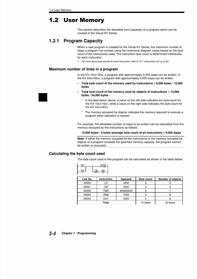
1.2.1 Program Capacity
When a user program is created for the Visual KV Series, the masteps a program can contain using the mnemonic diagram variescount of the instructions used. The instruction byte count is deterfor each instruction.
For more about byte counts for each instruction, refer to "2.1 Instruction List
Maximum number of lines in a program
In the KV-10xx/16xx, a program with approximately 2,000 steps cthe KV-24xx/40xx, a program with approximately 4,000 steps can
• Total byte count of the memory used by instructions ≤ 6,0bytes
• Total byte count of the memory used by objects of instrubytes / 24,000 bytes
* In the description above, a value on the left side indicates tthe KV-10xx/16xx, while a value on the right side indicatesthe KV-24xx/40xx.
* The memory occupied by objects indicates the memory reqprogram when operation is started.
For example, the allowable number of steps to be written can be memory occupied by the instructions as follows.
12,000 bytes / 3 bytes (average byte count of an instructio
Note: If either the memory occupied by the instructions or the meobjects of a program exceeds the specified memory capacity, thebe written or executed.
Calculating the byte count used
The byte count used in this program can be calculated as shown
T0000500
0000
0500
#00020 T000
7/18/2019 Keyence Programming
http://slidepdf.com/reader/full/keyence-programming 29/392
1.3 Device Configuration
"Device" is a general name for relays, registers, etc. p
This section describes the available devices in the Visgeneral use.
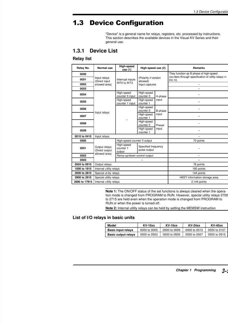
1.3.1 Device List
Relay list
Note 1: The ON/OFF status of the set functions is alwtion mode is changed from PROGRAM to RUN. Howe
.oNyaleR esulamroN deeps-hgiH
)1(esu )2(esudeeps-hgiH
0000
syalertupnItupnitceriD()aeradewolla
stupnitpurretnI3TNIot0TNI
noisrevniytiraloP()dewolla
serutpactupnI
oitcnufyehTorhtsretnuoc
.01-VK1000
2000
3000
4000
syalertupnI
deeps-hgiHtupni0retnuoc
deeps-hgiH0retnuoc esahpA
tupni5000
deeps-hgiHtupni1retnuoc
deeps-hgiH1retnuoc
6000
–
deeps-hgiH0retnuoc esahpB
tupni7000
deeps-hgiH1retnuoc
8000 deeps-hgiH
0retnuoc teserPtupni
9000 deeps-hgiH
1retnuoc
5140ot0100 syalertupnI
0050
syalertuptuOtuptuotceriD()aeradewolla
tuptuo0retnuocdeeps-hgiH
1050deeps-hgiH
1retnuoctuptuo
ycneuqerfdeificepStuptuoeslup
2050 tuptuolortnocnwod / pu-pmaR
3050 –
5190ot4050 syalertuptuO
5191ot0001 syalerytilitulanretnI
5182ot0002 syalerytilitulaicepS
5192ot0092 syalerytilitulaicepS EKH
51971ot0003 syalerytilitulanretnI
1.3 Device Configuration
7/18/2019 Keyence Programming
http://slidepdf.com/reader/full/keyence-programming 30/392
1
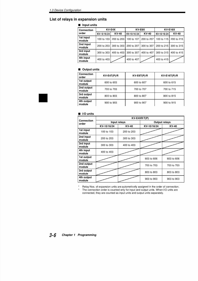
List of relays in expansion units
Input units
Output units
I/O units
noitcennoC
redro
X4E-VK X8E-VK
42/61/01-VK 04-VK 42/61/01-VK 04-VK 1-VK
tupnits1eludom
301ot001 302ot002 701ot001 702ot002 001
tupnidn2eludom
302ot002 303ot003 702ot002 703ot003 002
tupnidr3eludom
303ot003 304ot004 703ot003 704ot004 003
tupniht4eludom
304ot004 704ot004 004
noitcennoCredro
R/)P(T4E-VK R/)P(T8E-VK
tuptuots1eludom
306ot006 706ot006
tuptuodn2eludom
307ot007 707ot007
tuptuodr3eludom
308ot008 708ot008
tuptuoht4eludom
309ot009 709ot009
noitcennoC
redro
)P(T/RX4E-VK
syalertupnI ptuO42/61/01-VK 04-VK 42/61/01-VK
tupnits1eludom
301ot001 302ot002
tupnidn2eludom
302ot002 303ot003
tupnidr3eludom
303ot003 304ot004
tupniht4
eludom 304ot004tuptuots1
eludom 606ot306
tuptuodn2eludom
307ot307
tuptuodr3308t308

7/18/2019 Keyence Programming
http://slidepdf.com/reader/full/keyence-programming 31/392
1.3.2 Relay No.
The relay No. configuration is shown below.
Address No.
Address Nos. are assigned to basic units, input expanunits, and I/O expansion units. Zero to 4 are assignedassigned to output units. Address Nos. assigned in a of I/O terminals and the connection position of the uni
* 2 to 4 in KV-40xx
Address No. assignment procedure
• The address No. is represented as a number 0 to 9• Address Nos. 0 to 4 are provided for inputs, while vided for outputs.
1 2 5 1 5Channel No.
Contact No.(00 to 15)
Address No.
(Input: 0 to 4, output: 5 to 9)
ModelKV-10xx
Basic unitsKV-16xx
KV-24xx
KV-40xx
kV-E4X
Input expansion units KV-E8X
KV-E16X
KV-E4R/E4T(P)
Output expansion units KV-E8R/E8T(P)
KV-E16R/E16T(P)
I/O expansion units KV-E4XR/E4XT(P)
1.3 Device Configuration
7/18/2019 Keyence Programming
http://slidepdf.com/reader/full/keyence-programming 32/392
1
Contact No.
• Contact Nos. are input/output terminal Nos. of basic units, inpoutput expansion units, and I/O expansion units.
• The contact No. is represented as a number 0 to 15.
Example
In the KV-E4X, with 4 input terminals, the contact Nos. are 0 tE16T(P), with 16 input terminals, the contact Nos. are 0 to 15
• In a unit with 16 or more terminals, the contact No. of the 17th0 and its address No. is increased by 1.
Example
In the KV-40AR, with 40 terminals (24 input and 16 output terNo. 0 is assigned to input terminal Nos. 1 to 16 and address Ninput terminal Nos. 17 to 24
Channel No.
The channel No. is the higher order digit in the contact No.
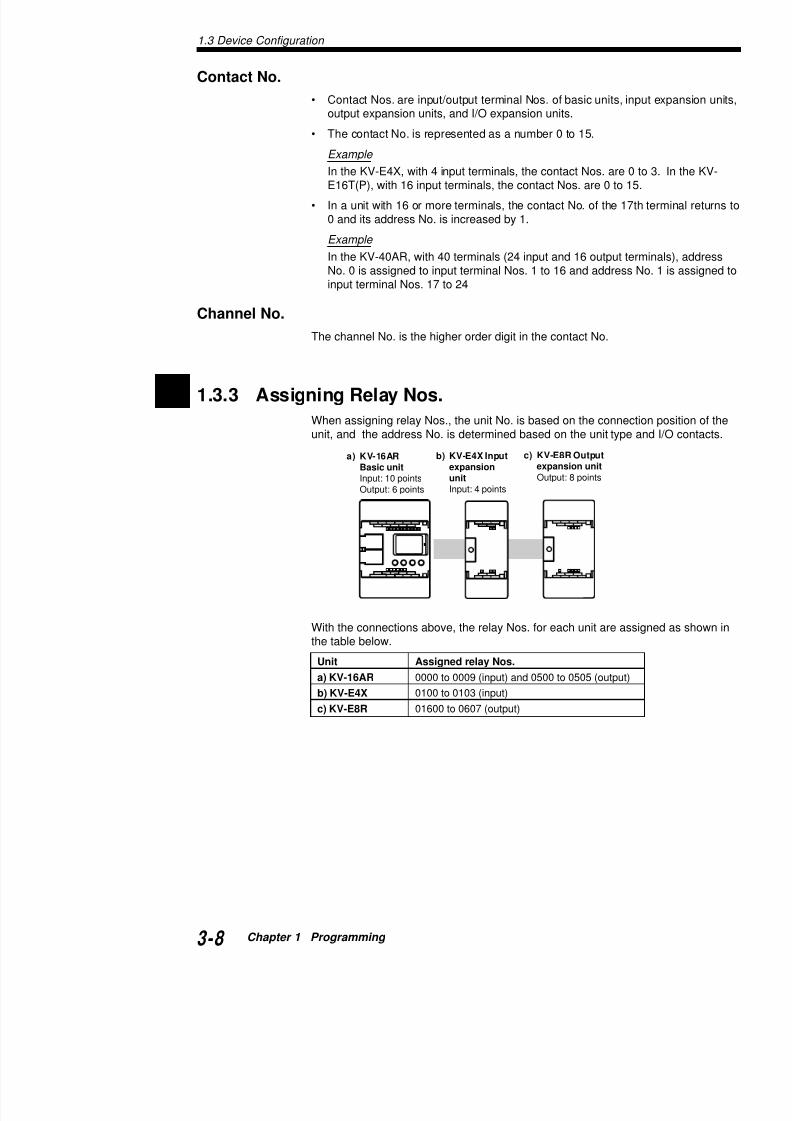
1.3.3 Assigning Relay Nos.
When assigning relay Nos., the unit No. is based on the connectunit, and the address No. is determined based on the unit type a
With the connections above, the relay Nos. for each unit are assithe table below.
a) KV-16ARBasic unitInput: 10 points
Output: 6 points
b) KV-E4X Inputexpansionunit
Input: 4 points
c) KV-E8R Outputexpansion unitOutput: 8 points
Unit Assigned relay Nos.
a) KV-16AR 0000 to 0009 (input) and 0500 to 0505 (output)

7/18/2019 Keyence Programming
http://slidepdf.com/reader/full/keyence-programming 33/392
1.3.4 Input Relays
Input relays receive ON/OFF signals sent from extern
Note 1: Input relays function as contacts in programs.coils (outputs).
Note 2: There is no restriction of the contact type (N.Orelay Nos. are used, or the number of relays used.
Basic unit
Input relay time constant
Though the time constant is usually 10 ms ±20%, it cafollowing settings.
• When the HSP instruction is used: 10 µs ±20%
• While special utility relay 2813 remains ON, the tim7 steps by setting data memory DM1940 as follows
When DM1940 is set to 0: 10µs ±20%1: 20 µs ±20%
2: 500 µs ±20%3: 1 ms ±20%4: 2.5 ms ±20%5: 5 ms ±20%6: 10 ms ±20%Never set a numeric va
For more about changing the input time constant, refer to "1.4.Function" (p.3-23).
Hardware input (independent of scan time)
• High-speed counterWhen the time constant is set to 10 µs using the HDM1940 (only while special utility relay 2813 remaresponse of input relays 0004 and 0005 of CTH0 a
• INT instruction: 0000 to 0003This instruction can receive any signal without regathe signal ON time is longer than the input time co
"HSP instruction" (p.3-86), "INT instruction" (p.3-192), "4.1 High (p.3-204)
Note 1: While special utility relay 2813 remains ON, thifi d f ll i t l i b i it
1.3 Device Configuration

7/18/2019 Keyence Programming
http://slidepdf.com/reader/full/keyence-programming 34/392
1
Expansion unit
Input relay time constant
By setting special utility relays 2609 to 2612 to ON, the time cons
sion units can be set to 10 µs.
* Not available with the KV-40xx
1.3.5 Output Relays
Output relays output the program execution results to the outsidetypes of outputs, relay and transistor.
Note 1: Output relays function as contacts and relay coils in prog
Note 2: There is no restriction of the contact type (N.O. or N.C.) relay Nos. are used, or the number of relays used.
Output operation time
• Transistor output
OFF ON: 50 µs or less (10 µs or less in 500 to 502)ON OFF: 250 µs or less (10 µs or less in 500 to 502, 100 µ
outputs in the basic unit)
• Relay outputOFF ON: 10 ms or lessON OFF: 10 ms or less
ytilitulaicepS.oNyaler
noitcnuF
*9062 tinunoisnapxetupnifotnatsnocemittupnI
5110ot0010.soNyalerhtiw FFO
0162 tinunoisnapxetupnifotnatsnocemittupnI
5120ot0020.soNyalerhtiw FFO
1162 tinunoisnapxetupnifotnatsnocemittupnI
5130ot0030.soNyalerhtiw
FFO
2162 tinunoisnapxetupnifotnatsnocemittupnI
5140ot0040.soNyalerhtiw FFO
epyttuptuorotsisnarT ptuoyaleR
)P(TD / )P(TA01-VK )P(TD / )P(TA61-VK RD / RA01-VK K
)P(TD / )P(TA42-VK )P(TD / )P(TA04-VK RD / RA42-VK K
T4E-VK )P(T8E-VK R4E-VK K
)P(T61E-VK )P(TX4E-VK R61E-VK K

7/18/2019 Keyence Programming
http://slidepdf.com/reader/full/keyence-programming 35/392
1.3.6 Internal Utility Relays
In a relay circuit, when one relay contact is used twicemulti-pole relay with the same number of poles as the
Internal utility relays function only in programs, and elcircuits to facilitate circuit design.
Note 1: Internal utility relays function as contacts and
Note 2: There is no restriction of the contact type (N.Orelay Nos. are used, or the number of relays used.
Retentive function of internal utility relays
Except for internal utility relays, all relays turn OFF whchanged or when operation is stopped via a power shrestarted, all relays remain OFF except relays whose ever, internal utility relays can be set using the MEMSnot they are to be retained. (Internal utility relays 2700retained.)
When an internal utility relay is set to be retained, its O
the power is turned off. By using the retained relay all relays which are set to be retained can be set to OFF.
For more about setting the memory switch, refer to "MEMSW in
Application example of a retentive function: Lift ve
Internal utility relays 1000 and 1001 are set to be retaWhen the upper/lower limit switch turns ON, the directinverted. Even if the power is turned off while the lift is
continues to move up (or down) when the power is tur
(0000)
(0500)
(0001)
Move-up
Upper limitswitch
Lower limitswitch
Move-down
1.3 Device Configuration

7/18/2019 Keyence Programming
http://slidepdf.com/reader/full/keyence-programming 36/392
1
1.3.7 Special Utility Relays
Each special utility relay has a unique function. By using special tively, programs can be simplified and program control improved
Note 1: A special utility relay can be used as many times as des
Note 2: Special utility relays dedicated for reading can be used acannot be used as outputs.
For more about relays dedicated for reading, refer to "1.3.8 Special Utility Rela
Description
Relay 2002: Always ON
By setting an output relay to ON using relay 2002, the output rela"running indicator output".
Relay 2003: Always OFF.
Opposite that of relay 2002, use relay 2003 where it is not requireFor example, when using only the up function of an up/down couin the DW (down) input.
Relays 2004, 2005 and 2006: Clock pulse
For each relay, the time ratio is "ON:OFF = 1:1". (Accordingly, th2005 is 0.05 sec/pulse.)However, because these relays depend on the scan time, error atime is generated.
• By combining an output relay, an "intermittent output" can be • By using relay 2006 as input for a counter, the counter can be
term timer.
2002
00000LDA
DM0000STA
2002
HSP0100
Set the input time constant of relay 0100 to 10 µs.Transfer the ON/OFF status data of channel 0000 to DM0000.
C000
1000 #03600
2006C000
1000
7/18/2019 Keyence Programming
http://slidepdf.com/reader/full/keyence-programming 37/392
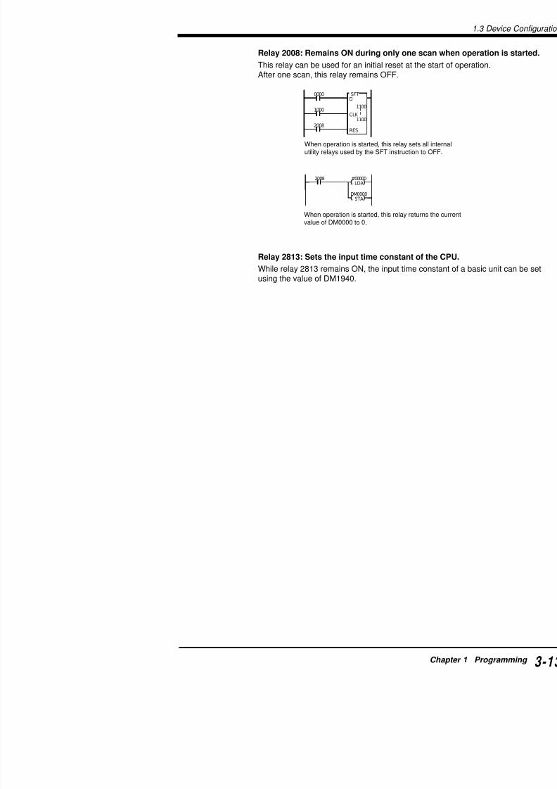
Relay 2008: Remains ON during only one scan wh
This relay can be used for an initial reset at the start oAfter one scan, this relay remains OFF.
Relay 2813: Sets the input time constant of the CP
While relay 2813 remains ON, the input time constantusing the value of DM1940.
When operation is started, this relay sets all internautility relays used by the SFT instruction to OFF.
0000
1000
SFTD
CLK
RES2008
1100
1100
#00000LDA
DM0000STA
2008
When operation is started, this relay returns the curvalue of DM0000 to 0.
1.3 Device Configuration

7/18/2019 Keyence Programming
http://slidepdf.com/reader/full/keyence-programming 38/392
1
1.3.8 Special Utility Relay List
Special relays and arithmetic operation flags
"1.3.7 Special Utility Relays" (p.3-12)
* Read-only relay.
Special utility relays for high-speed counter(0)
"Chapter 4. High-Speed Counters" (p.3-203)
.oNyaleR noitcnuF
*0012 1(0HTCrofylnodesukcolclanretnI µ )s
*1012 01(0HTCrofylnodesukcolclanretnI µ )s
*2012 001(0HTCrofylnodesukcolclanretnI µ )s
3012 0CTCrotarapmocnehw0HTCforaelccitamotuA.NOsnrut
OO
4012 nehw0050ottuptuotceridstimrep / stibihorP.NOsnrut0CTCrotarapmoc
OO
5012 rotarapmocnehwFFOottessi0050ottuptuotceriD.NOsnrut0CTC
OO
6012 rotarapmocnehwNOottessi0050ottuptuotceriD.NOsnrut0CTC
OO
7012 hcaedesreversi0050ottuptuofosutatsFFO / NO
.NOsnrut0CTCrotarapmocemit
O
O
8012 nehw0050ottuptuotceridstimrep / stibihorP.NOsnrut1CTCrotarapmoc
OO
9012 rotarapmocnehwFFOottessi0050ottuptuotceriD.NOsnrut1CTC
OO
0112 rotarapmocnehwNOottessi0050ottuptuotceriD O
.oNyaleR noitcnuF
*2002 .NOsyawlA
*3002 .FFOsyawlA
*4002 )%05:elcycytud(eslupkcolcs-10.0
*5002 )%05:elcycytud(eslupkcolcs-1.0
*6002 )%05:elcycytud(eslupkcolcs-0.1
*7002 .putratsretfanacstsrifgnirudFFOsniameR*8002 .putratsretfanacstsrifgnirudNOsniameR
*9002 evitagensinoitarepocitemhtirafotlusernehwNOsnruT
.detarenegsiwolfrevo
*0102 .0sinoitarepocitemhtirafotlusernehwNOsnruT
*1102 .evitisopsinoitarepocitemhtirafotlusernehwNOsnruT
*2102 renasetarenegnoitarepocitemhtirananehwNOsnruT

7/18/2019 Keyence Programming
http://slidepdf.com/reader/full/keyence-programming 39/392
Special utility relays for high-speed counter(1)
"Chapter 4. High-Speed Counters" (p.3-203)
* Read-only relay.
Note: Never use special utility relays that are not show
Other special utility relays
.oNyaleR noitcnuF
*0022 1(1HTCrofylnodesukcolclanretnI µ )s
*1022 01(1HTCrofylnodesukcolclanretnI µ )s
*2022 001(1HTCrofylnodesukcolclanretnI µ )s
3022 Crotarapmocnehw1HTCforaelccitamotuA.NOsnrut
4022 nehw1050ottuptuotceridstimrep / stibihorP.NOsnrut2CTCrotarapmoc
5022 ocnehwFFOottessi1050ottuptuotceriD
.NOsnrut2CTC
6022 mocnehwNOottessi1050ottuptuotceriD.NOsnrut2CTC
7022 desreversi1050ottuptuofosutatsFFO / NO.NOsnrut2CTCrotarapmocemit
8022 nehw1050ottuptuotceridstimrep / stibihorP.NOsnrut3CTCrotarapmoc
9022 ocnehwFFOottessi1050ottuptuotceriD.NOsnrut3CTC
0122 mocnehwNOottessi1050ottuptuotceriD.NOsnrut3CTC
1122 desreversi1050ottuptuofosutatsFFO / NO.NOsnrut3CTCrotarapmocemit
2122 Crotarapmocnehw1HTCforaelccitamotuA.NOsnrut
3122 CrotarapmocrofedomnoitacilpitlumstceleSNOFFONOFFO
p2:NO4x:NO2x:FFOeslup1:FFO4122
noitacilpitluMedom
eslup1 2x
3122 FFO NO
4122 FFO FFO
.oNyaleR noitcnuF
0032 delbasidstuptuolanretxE
)5190ot0050stuptuo(
1032delbasidstupnihserferlanretxE
1.3 Device Configuration
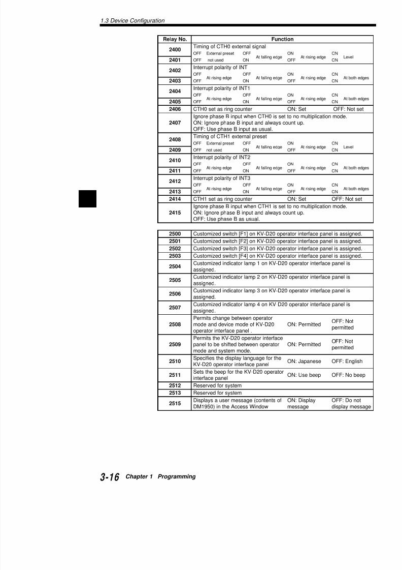
7/18/2019 Keyence Programming
http://slidepdf.com/reader/full/keyence-programming 40/392
1
.oNyaleR noitcnuF
0042 langislanretxe0HTCfognimiT
FFO teserplanretxE FFOegdegnillaftA
NOegdegnisirtA
1042 FFO desuton NO FFO
2042 TNIfoytiraloptpurretnIFFO
egdegnisirtAFFO
egdegnillaftANO
egdegnisirtA3042 FFO NO FFO
4042 1TNIfoytiraloptpurretnI
FFOegdegnisirtA
FFOegdegnillaftA
NOegdegnisirtA
5042 FFO NO FFO
6042 retnuocgnirsates0HTC teS:NO
7042tacilpitlumonottessi0HTCnehwtupniBesahperongI
.putnuocsyawladnatupniBesahperongI:NO
.laususatupniBesahpesU:FFO
8042 teserplanretxe1HTCfognimiT
FFO teserplanretxE FFOegdegnillaftA
NOegdegnisirtA
9042 FFO desuton NO FFO
0142 2TNIfoytiraloptpurretnI
FFOegdegnisirtA
FFOegdegnillaftA
NOegdegnisirtA
1142 FFO NO FFO
2142 3TNIfoytiraloptpurretnI
FFO
egdegnisirtA
FFO
egdegnillaftA
NO
egdegnisirtA3142 FFO NO FFO
4142 retnuocgnirsates1HTC teS:NO
5142tacilpitlumonottessi1HTCnehwtupniBesahperongI
.putnuocsyawladnatupniBesahperongI:NO.laususaBesahpesU:FFO
0052 apecafretnirotarepo02D-VKno]1F[hctiwsdezimotsuC
1052 apecafretnirotarepo02D-VKno]2F[hctiwsdezimotsuC
2052 apecafretnirotarepo02D-VKno]3F[hctiwsdezimotsuC3052 apecafretnirotarepo02D-VKno]4F[hctiwsdezimotsuC
4052 afretnirotarepo02D-VKno1pmalrotacidnidezimotsuC
.dengissa
5052 afretnirotarepo02D-VKno2pmalrotacidnidezimotsuC
.dengissa
6052 afretnirotarepo02D-VKno3pmalrotacidnidezimotsuC
.dengissa
7052 afretnirotarepo02D-VKno4pmalrotacidnidezimotsuC
.dengissa
8052rotareponeewtebegnahcstimreP02D-VKfoedomeciveddnaedom
.lenapecafretnirotarepodettimreP:NO
9052ecafretnirotarepo02D-VKehtstimreP
rotareponeewtebdetfihsebotlenap dettimreP:NO

7/18/2019 Keyence Programming
http://slidepdf.com/reader/full/keyence-programming 41/392
.oNyaleR noitcnuF
9062 wtinunoisnapxetupnifotnatsnocemittupnI
5110ot0010.soN
0162 wtinunoisnapxetupnifotnatsnocemittupnI
5120ot0020.soN
1162 wtinunoisnapxetupnifotnatsnocemittupnI
5130ot0030.soN
2162 wtinunoisnapxetupnifotnatsnocemittupnI
5140ot0040.soN
3162 tcennocsidnoisnapxetatupnifogniraelC
2172 lamroN:FFOrorretcennocsiD
tinudetcennocninoitcennocsiD:NO
4172 tiucricnoitcerroctupnideeps-hgihfoesU
desutoN:FFOdesU:NO
5172 .noitareponisihctiwsmacelihwNO
0082 AtropnoitacinummocotdneslangiskaerB
1082 tropnoitacinummocmorfatadtxetsevieceR
.atadtxetgniviecerelihwnacs1
2082ecnatpeccaatadtxetAtropnoitacinummoCelihwdeviecersiatadtxetnehwNOnacs1
.NOsi
3082 orreevieceratadtxetAtropnoitacinummoC
txetanehwnacs1ylnognirudNOsniameR
4082 (tratsdnesatadtxetAtropnoitacinummoC
5082 BtropnoitacinummocotdneslangiskaerB
6082 na,atadtxetBtropnoitacinummocsevieceR
.atadtxetgniviecerelihwnacs
7082ecnatpeccaatadtxetBtropnoitacinummoCetnehwNOnacs1ylnognirudNOsniameR
.NOsi8082yalerro6082yaler
8082 orreevieceratadtxetBtropnoitacinummoC
txetanehwnacs1ylnognirudNOsniameR
9082 (tratsdnesatadtxetBtropnoitacinummoC
1.3 Device Configuration
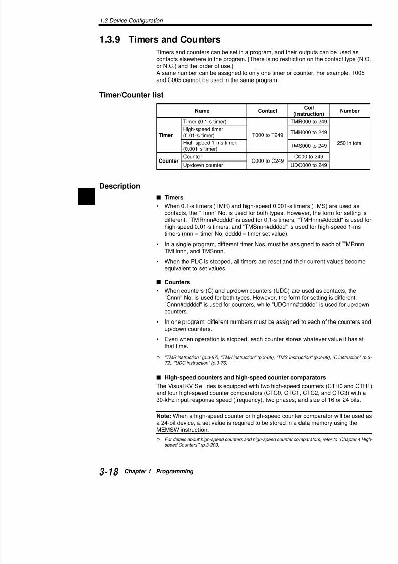
7/18/2019 Keyence Programming
http://slidepdf.com/reader/full/keyence-programming 42/392
1
1.3.9 Timers and Counters
Timers and counters can be set in a program, and their outputs ccontacts elsewhere in the program. [There is no restriction on the
or N.C.) and the order of use.]A same number can be assigned to only one timer or counter. Foand C005 cannot be used in the same program.
Timer/Counter list
Description Timers
• When 0.1-s timers (TMR) and high-speed 0.001-s timers (TMcontacts, the "Tnnn" No. is used for both types. However, the different. "TMRnnn#ddddd" is used for 0.1-s timers, "TMHnnnhigh-speed 0.01-s timers, and "TMSnnn#ddddd" is used for htimers (nnn = timer No, ddddd = timer set value).
• In a single program, different timer Nos. must be assigned to TMHnnn, and TMSnnn.
• When the PLC is stopped, all timers are reset and their currenequivalent to set values.
Counters
• When counters (C) and up/down counters (UDC) are used as"Cnnn" No. is used for both types. However, the form for setti"Cnnn#ddddd" is used for counters, while "UDCnnn#ddddd" iscounters.
• In one program, different numbers must be assigned to each up/down counters.
• Even when operation is stopped, each counter stores whatevth t ti
emaN tcatnoC lioC
noitcurtsni(
remiT
)remits-1.0(remiT
942Tot000T
2ot000RMT
remitdeeps-hgiH)remits-10.0(
2ot000HMT
remitsm-1deeps-hgiH)remits-100.0(
2ot000SMT
retnuoCretnuoC
942Cot000C942ot000C
retnuocnwod / pU 2ot000CDU

7/18/2019 Keyence Programming
http://slidepdf.com/reader/full/keyence-programming 43/392
1.3.10 Data Memories
Data memories store various types of data.Data memories are not usually used in a program that
timers, and counters. When arithmetic instructions areries can be used to store data for arithmetic operationarithmetic operations.
.oNMD ircseD
999MDot0MD esuybdesuebnac(deificepstoN
9901MDot0001MD AtropeviecertxeT
9911MDot0011MD AtropdnestxeT
9921MDot0021MD BtropeviecertxeT9931MDot0031MD BtropdnestxeT
0041MD tuotsrifehT:noitcnufhctiwsmaC
1041MD nosirapmoC:noitcnufhctiwsmaC
edom
2041MD tnuocesluP:noitcnufhctiwsmaC
0HTCot
3041MD esuybdesuebnac(deificepstoN
4041MD )sm(elcyctnemerusaeM5041MD )zH(tnuocycneuqerffotluseR
7041MD/6041MD foeulavteS:noitcnufhctiwsmaC
FFO / NOsnrut
9041MD/8041MD:
9641MD/8641MD
foeulavteS:noitcnufhctiwsmaCFFO / NOsnrut
:foeulavteS:noitcnufhctiwsmaC
FFO / NOsnrut
0741MD uebtonnac(metsysybdevreseR
9741MDot1741MD esuybdesuebnac(deificepstoN
0841MD S:noitcnuflortnocnwod / pu-pmaR
)000,05
1841MD O:noitcnuflortnocnwod / pu-pmaR
)000,05
2841MD A:noitcnuflortnocnwod / pu-pmaR
)000,4ot0(
3841MD esuybdesuebnac(deificepstoN
4841MD O:noitcnuflortnocnwod / pu-pmaR
)535,56ot0(
5841MD O:noitcnuflortnocnwod / pu-pmaR
)535,56ot0(
6841MD E:noitcnuflortnocnwod / pu-pmaR
1.3 Device Configuration
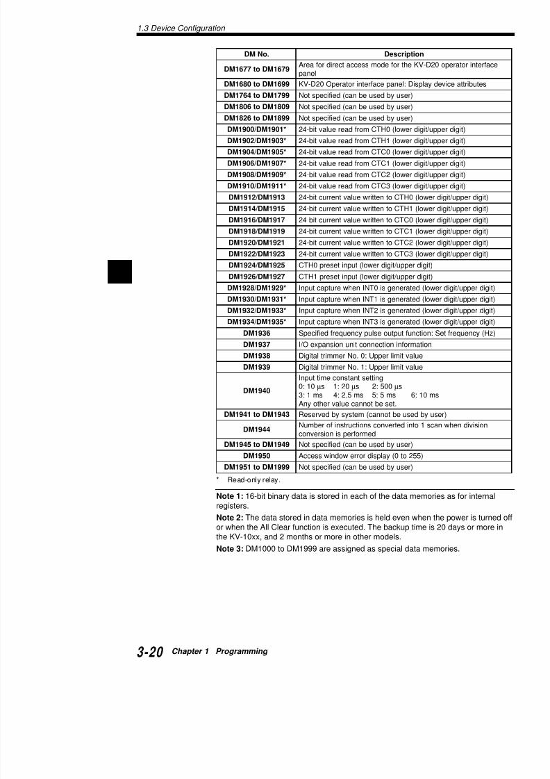
7/18/2019 Keyence Programming
http://slidepdf.com/reader/full/keyence-programming 44/392
1
.oNMD noitpircseD
9761MDot7761MD o02D-VKehtrofedomsseccatceridrofaerA
lenap
9961MDot0861MD vedyalpsiD:lenapecafretnirotarepO02D-VK
9971MDot4671MD )resuybdesuebnac(deificepstoN
9081MDot6081MD )resuybdesuebnac(deificepstoN
9981MDot6281MD )resuybdesuebnac(deificepstoN
*1091MD/0091MD eppu / tigidrewol(0HTCmorfdaereulavtib-42
*3091MD/2091MD eppu / tigidrewol(1HTCmorfdaereulavtib-42
*5091MD/4091MD eppu / tigidrewol(0CTCmorfdaereulavtib-42
*7091MD/6091MD eppu / tigidrewol(1CTCmorfdaereulavtib-42
*9091MD/8091MD eppu / tigidrewol(2CTCmorfdaereulavtib-42*1191MD/0191MD eppu / tigidrewol(3CTCmorfdaereulavtib-42
3191MD/2191MD gidrewol(0HTCotnettirweulavtnerructib-42
5191MD/4191MD gidrewol(1HTCotnettirweulavtnerructib-42
7191MD/6191MD gidrewol(0CTCotnettirweulavtnerructib-42
9191MD/8191MD gidrewol(1CTCotnettirweulavtnerructib-42
1291MD/0291MD gidrewol(2CTCotnettirweulavtnerructib-42
3291MD/2291MD gidrewol(3CTCotnettirweulavtnerructib-42
5291MD/4291MD )tigidreppu / tigidrewol(tupniteserp0HTC
7291MD/6291MD )tigidreppu / tigidrewol(tupniteserp1HTC
*9291MD/8291MD rewol(detarenegsi0TNInehwerutpactupnI
*1391MD/0391MD rewol(detarenegsi1TNInehwerutpactupnI
*3391MD/2391MD rewol(detarenegsi2TNInehwerutpactupnI
*5391MD/4391MD rewol(detarenegsi3TNInehwerutpactupnI
6391MD eS:noitcnuftuptuoeslupycneuqerfdeificepS
7391MD noitamrofninoitcennoctinunoisnapxeO / I
8391MD eulavtimilreppU:0.oNremmirtlatigiD
9391MD eulavtimilreppU:1.oNremmirtlatigiD
0491MD
gnittestnatsnocemittupnI01:0 µ 02:1s µ 005:2s µs
sm01:6sm5:5sm5.2:4sm1:3.tesebtonnaceulavrehtoynA
3491MDot1491MD resuybdesuebtonnac(metsysybdevreseR
4491MD nacs1otnidetrevnocsnoitcurtsniforebmuNdemrofrepsinoisrevnoc
9491MDot5491MD )resuybdesuebnac(deificepstoN
0591MD )552ot0(yalpsidrorrewodniwsseccA
9991MDot1591MD )resuybdesuebnac(deificepstoN
1 3 11 T D t M

7/18/2019 Keyence Programming
http://slidepdf.com/reader/full/keyence-programming 45/392
1.3.11 Temporary Data Memory
These data memories are used for temporary storageare used, temporary data memories can be used to te
arithmetic operations as well as the results of arithmet
Attribute R: Read W: Write
* Both R and W are enabled when special functions are n
Note 1: Temporary data memories are initialized whe
Note 2: TM20, TM30, and TM31 are read-only, so canHowever, TM28 can be used for both reading and writused.
Note 3: TM00 and TM01 are used by the MUL and DIfor any other purpose.
.oNMT egasU
00MT LUM / VID(snoitarepocitemhtirarofdesU
10MT )VID(snoitarepocitemhtirarofdesU
72MTot20MT )resuybdesuebnac(deificepstoN
82MT dnoyeb)sm1:eludom(emitnacsserotS
emrofrepsinoitarepoemitnacstnatsnoc
92MT
tsnocfo)sm1:eludom(eulavtesserotS
noitarepo 03MT oitpurretni3TNInehweulav0CTCserotS
13MT eulavnaem(emitnacsderusaemserotS
.)sm1.0:eludom()snacs
1.3 Device Configuration
1 3 12 Relay Nos and Functions

7/18/2019 Keyence Programming
http://slidepdf.com/reader/full/keyence-programming 46/392
1
1.3.12 Relay Nos. and Functions
Assignment of Relay Nos.The components of a relay no. are shown below.
Unit Nos.
Unit nos. are assigned to units within the KV-300 system, with ththe right of the KV-300 CPU (see the figure below) assigned as nassigned as unit no. 0.
Address Nos.
Address nos. are assigned to the input units, output units, and I/OThe following table shows the assignment of address nos. to uni
0 7 5 1 5
Address No.
Channel No. Relay No. (00 t
Module No. (07 to 17)Input (0 to 4)Output (5 to 9)
Power supply unit CPU
0 7 8 9
Unit
KV-300 CPU CPU
KV-C16X 16-input unit
KV-C32X 32-input unit
KV-B16R 16-output unit
KV-B16S 16-output unit
KV-C32T 32-output unit
1 4 Special Functions

7/18/2019 Keyence Programming
http://slidepdf.com/reader/full/keyence-programming 47/392
1.4 Special Functions
This section describes special functions to set and co
KV Series, and useful functions for program debugginequipment.
1.4.1 Input Time Constant Change Function
The input time constant can be changed when a signaWhen connecting external equipment which has no coas transistor outputs does not occur, and inputting pultime constant change function can be used to decreas
Setting the input time constant for basic units using sp
The input time constant for a basic unit can be changeand special utility relay 2813.Though the input time constant is usually 10 ms, it cancorresponds to the number stored in DM1940 by settiON.If the HSP instruction and special utility relay 2813 are
priority is given to the HSP instruction and the numbe
Special utility relay 2813
OFF: Sets the input time constant to 10 ms.ON: Refers to the number stored in DM1940, then d
constant.
Note 1: Be sure to set the input time constant to 10 µs whencounter input.
Note 2: Never enter a number that is 7 or larger to data mem
Note 3: The input time constant specified by data memory Drising edge of special utility relay 2813.
T h h i i fi h d
0491MDniderotsrebmuN tnatsnocemittupnI
0 01 µs
1 02 µs
2 005 µs
3 sm1
4 sm5.2
5 sm5
6 sm01
eromro7 dewollatoN
1.4 Special Functions
1 4 2 Modifying the Input Relay Time Constant KV
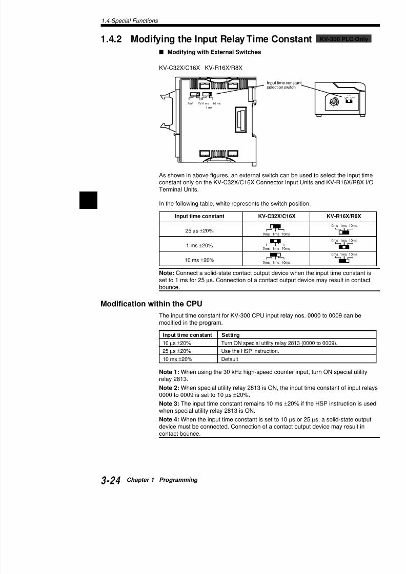
7/18/2019 Keyence Programming
http://slidepdf.com/reader/full/keyence-programming 48/392
1
1.4.2 Modifying the Input Relay Time Constant
Modifying with External Switches
KV-C32X/C16X KV-R16X/R8X
As shown in above figures, an external switch can be used to selconstant only on the KV-C32X/C16X Connector Input Units and K
Terminal Units.
In the following table, white represents the switch position.
Note: Connect a solid-state contact output device when the inputset to 1 ms for 25 µs. Connection of a contact output device maybounce.
Modification within the CPU
The input time constant for KV-300 CPU input relay nos. 0000 to modified in the program.
5V24V 10 ms0 ms
1 ms
Input time constantselection switch
Input time constant KV-C32X/C16X K
25 µs ±20%
1 ms ±20%
10 ms ±20%
0ms 1ms 10ms
0ms 1ms 10ms
0ms 1ms 10ms
Input time constant Setting
10 µs ±20% Turn ON special utility relay 2813 (0000 to 00
25 µs ±20% Use the HSP instruction
KV
1.4.3 Constant ScanTime Mode

7/18/2019 Keyence Programming
http://slidepdf.com/reader/full/keyence-programming 49/392
1.4.3 Constant Scan Time Mode
This function executes a program while keeping the scwhich usually changes based on the processing conte
how to set this function.
Though the scan time changes usually depending on be kept at a constant value by using this function. Thacquire data from external equipment at a constant timThe set value should be longer than the maximum scais kept at a constant value until the end of processing.
Setting procedure
Set the desired scan time to temporary data memory TSet special utility relay 2303 to ON.The scan time is written to TM31.The scan time can be set in 1-ms increments.Enter the desired scan time (ms) to the temporary dat
Setting example
In this example, the scan time is kept at 20 ms.
Note 1: Be sure to set the constant scan time value soscan time.
Note 2: If the actual scan time exceeds the set scan tturns ON (during the next 1 scan) while the actual sca1 ms).
Note 3: The scan time can be set up to 200 ms in tema value larger than 200 ms is input, it will be treated a
2008 2303SET
TM29STA
#00020LDA
1.4 Special Functions
1.4.4 Output Disabled Function

7/18/2019 Keyence Programming
http://slidepdf.com/reader/full/keyence-programming 50/392
1
1.4.4 Output Disabled Function
This function disables outputs from each unit in RUN mode withoprogram used. By disabling external outputs, the program can be
external equipment is connected, even when output of signals toequipment is not desired.
Setting procedure
When special utility relay 2300 turns ON, all outputs from all outp0915) to the outside are cleared after 1 scan is finished.However, the display in the Access Window and the output indicacleared.
Setting example
By setting/resetting special utility relay 2300 using the Access WIncrediWare (DOS)" or "LADDER BUILDER for KV" programminor the KV-P3E(01) handheld programmer, the external output procan be used.External outputs are prohibited while input 0000 is ON. External ted, though, while input 0000 is OFF.
For more about operating procedures, refer to the "Chapter 6. Handheld Prog
1.4.5 Input Refresh Disabled Function
This function disables the update of inputs from each unit triggerefrom external equipment.
By disabling external input refresh, inputs from each unit can be monitor status without mechanical operations to enable a progra
Setting procedure
When special utility relay 2301 turns ON, input refresh (read of ininput relays (0000 to 0415 used by the QL Series) is skipped.In this status, inputs can be set to ON/OFF from the Access WindIncrediWare (DOS)" or "LADDER BUILDER for KV" programminor the KV-P3E(01) handheld programmer.
Setting example
By setting/resetting special utility relay 2301 using the Access WIncrediWare (DOS)" or "LADDER BUILDER for KV" programminor the KV-P3E(01) handheld programmer, the external input refre
0000 2300
1.4.6 Contact Comment Save Function
7/18/2019 Keyence Programming
http://slidepdf.com/reader/full/keyence-programming 51/392
• This function transfers contact comments to the ViIncrediWare (DOS)" or "LADDER BUILDER for KV
software.• The Visual KV Series can store not only programs
to each contact using the "KV IncrediWare (DOS)" KV" programming support software.A program may not be easy to understand if only dregistering comments to the contacts, the programmore efficiently maintained.
• The number of contact comments that can be tran
normal transfer and compression transfer.• The KV-D20 operator interface panel includes the
function.
For more about operating procedures, refer to "2.5 Entering CoSetting the comment transfer" (p.2-138).
Note 1: Line comments cannot be stored.
Note 2: The KV-P3E(01) handheld programmer cannoments.
Note 3: The KV-D20 operator interface panel cannot dwhich have been compressed and transferred.
1.4 Special Functions
1.4.7 Special Functions KV-300 PLC only

7/18/2019 Keyence Programming
http://slidepdf.com/reader/full/keyence-programming 52/392
1
p
Constant Scan Time Mode
In this mode, operation can take place according to a preset scan
Setting
Write the desired scan time into TM29 (temporary data memory)special utility relay No. 2303. The scan time can also be written iscan time in increments of 10 ms (a value of less than 10 ms is inHere, write a value into TM equivalent to 10 times the scan time.
Example
Set the constant scan time to 20 ms.
Note 1: The set value for the constant scan time must be greaterscan time. Otherwise, special utility relay 2304 turns on during evconstant scan time mode.
Note 2: If the scan time exceeds the set value, special utility reladuring the next scan.
Output Disabled Function
During checking of a program, this function clears output from ouless of the program currently running.
SettingTurn on special utility relay No. 2300. After one scan is complete(00500 to 00503, 07500 to 17915) are cleared.
Example
Use the output disabled function by executing FORCED RESET/utility relay No. 2300 from the monitor display.
To execute FORCED RESET or RESET, refer to "Chapter 6 Handheld Progr
Input Refresh Disabled Function
Set this function if it is desired to turn ON/OFF input relays from twithout activating the machine when checking a program.
LDA STA SET
02008 #00200 TM29 2303
1.5 Extended Ladder Diagrams
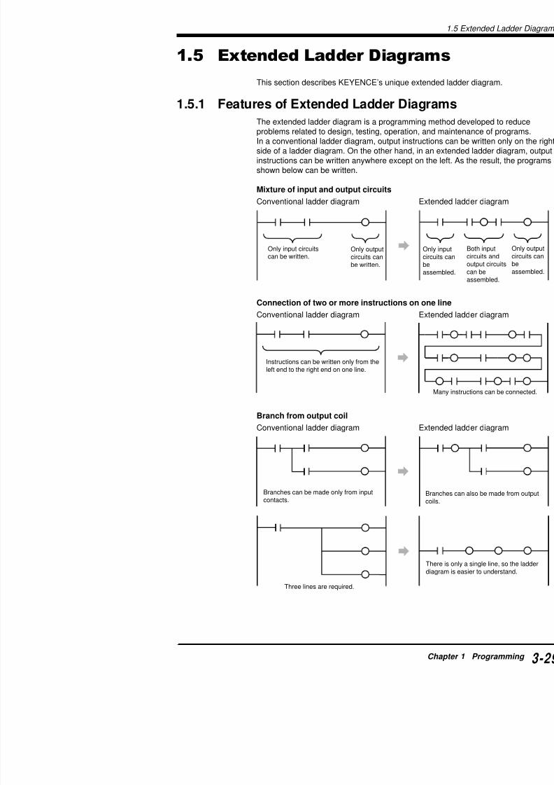
7/18/2019 Keyence Programming
http://slidepdf.com/reader/full/keyence-programming 53/392
g
This section describes KEYENCE’s unique extended
1.5.1 Features of Extended Ladder Diagram
The extended ladder diagram is a programming methoproblems related to design, testing, operation, and maIn a conventional ladder diagram, output instructions cside of a ladder diagram. On the other hand, in an extinstructions can be written anywhere except on the lefshown below can be written.
Mixture of input and output circuits
Conventional ladder diagram Extende
Connection of two or more instructions on one lin
Conventional ladder diagram Extende
Branch from output coil
Conventional ladder diagram Extende
Only input circuitscan be written.
Only outputcircuits can
be written.
Only inpcircuits c
beassembl
Instructions can be written only from theleft end to the right end on one line.
Many
1.5 Extended Ladder Diagrams
1.5.2 Advantages of Extended Ladder Diagrams
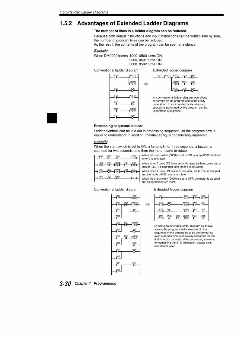
7/18/2019 Keyence Programming
http://slidepdf.com/reader/full/keyence-programming 54/392
1
2010
20102002
2010 05
05
05#01000
CMP
DM0000
LDA
#02000CMP
#03000CMP
2002 DM0000
LDA
#01000CMP
2002
2010
#02000CMP
0500
0501
2002
2010
#03000CMP
2010 0502
In a conventional ladder diagramperformed by the program cannounderstood. In an extended laddeoperations performed by the progunderstood at a glance.
When the start switch (0000) is set to ON,timer 0 is activated.
0000 1100
T000
T001
0500
0501
0502 0000
1000STG
1001STG
#00030 T000
#00020 T001
1002STG
1001 J MP
1002 J MP
ENDS
1100DIFU
1000SET
When timer 0 turns ON three seconds latebuzzer (0501) is sounded, and timer 1 is a
When timer 1 turns ON two seconds later,and the motor (0502) starts to rotate.
When the start switch (0000) is set to OFFand all operations are reset.
0000
T
1
0500
0000
1000 T000 #00010 T000
1000DIFU
1001STG
#00010 T000
1000DIFU
The number of lines in a ladder diagram can be reduced.
Because both output instructions and input instructions can be w
the number of program lines can be reduced.As the result, the contents of the program can be seen at a glanc
Example
When DM0000 stores 1000, 0500 turns ON.2000, 0501 turns ON.3000, 0502 turns ON.
Conventional ladder diagram Extended ladder diagram
Processing sequence is clear.
Ladder symbols can be laid out in processing sequence, so the peasier to understand. In addition, maintainability is considerably i
Example
When the start switch is set to ON, a lamp is lit for three seconds
sounded for two seconds, and then the motor starts to rotate.
Conventional ladder diagram Extended ladder diagram
Note: When an extended ladder diagram is used, the diagram may be reduced However this may not nece
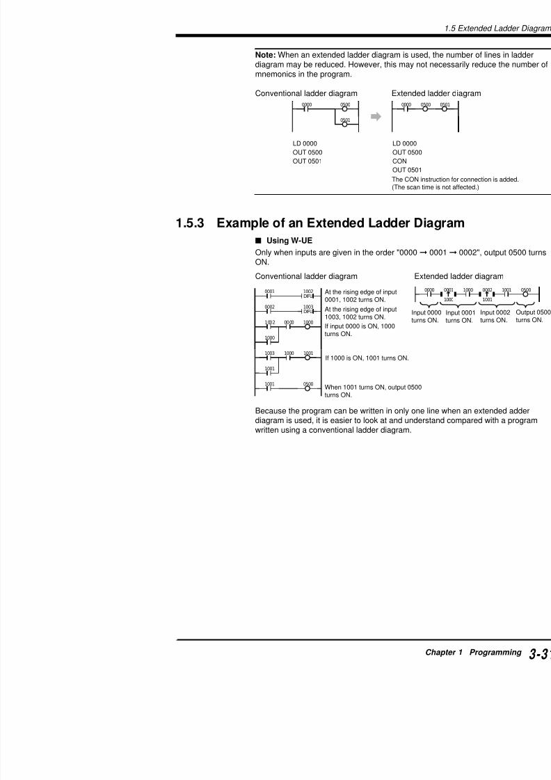
7/18/2019 Keyence Programming
http://slidepdf.com/reader/full/keyence-programming 55/392
0501
05000000
LD 0000
OUT 0500
OUT 0501
LD 0000
OUT 0500
CON
OUT 0501
0505000000
The CON instructio(The scan time is n
At the rising edge of input0001, 1002 turns ON.
0001
1000
1002 0000
0002
1000
1001
1003 1000 1001
1001 0500
1003DIFU
1002DIFU
0000
At the rising edge of input1003, 1002 turns ON.
If input 0000 is ON, 1000turns ON.
If 1000 is ON, 1001 turns ON.
When 1001 turns ON, output 0500turns ON.
Input 0000turns ON.
diagram may be reduced. However, this may not necemnemonics in the program.
Conventional ladder diagram Extended ladde
1.5.3 Example of an Extended Ladder Diagr
Using W-UE
Only when inputs are given in the order "0000 0001
ON.
Conventional ladder diagram Extended
Because the program can be written in only one line wdiagram is used, it is easier to look at and understand
written using a conventional ladder diagram.
1.5 Extended Ladder Diagrams

7/18/2019 Keyence Programming
http://slidepdf.com/reader/full/keyence-programming 56/392
1

7/18/2019 Keyence Programming
http://slidepdf.com/reader/full/keyence-programming 57/392
Chapter 2Instructions
Describes the concrete usage of instructions in the KVRefer to "Chapter 3 Interrupts" on page 3-191 for detaRefer to "Chapter 4 High-speed counters" on page 3-2speed counters used in the application instruction.
2.1 Instruction List [Visual KV Series] ..2.1.1 Basic Instructions ........................................2.1.2 Application Instructions ...............................2.1.3 Arithmetic Instructions .................................2.1.4 Interrupt Instructions ...................................2.1.5 Function No. List (Alphabetical order) .........
2.2 Instruction List [KV-300 Series, KV-1
2.2.1 Basic Instructions ........................................2.2.2 Application Instructions ...............................2.2.3 Arithmetic Instructions .................................2.2.4 Interrupt Instructions ...................................
2.3 Convention Details ............................
2.4 Instruction Details .............................2.4.1 Basic Instructions ........................................2.4.2 Application Instructions ...............................
2.4.3 Arithmetic Instructions .................................2.5 Programming Notes ..........................
2.1 Instruction List Visual KV Series
2.1 Instruction List Visual KV Series

7/18/2019 Keyence Programming
http://slidepdf.com/reader/full/keyence-programming 58/392
2
The KV Series uses 80 instructions.
The instructions are divided into four categories according to theinstructions, application instructions, arithmetic instructions, and tions.The following is an overview of applications and functions. For derespective description pages for each instruction.
2.1.1 Basic Instructions
LOAD LD
R No.T/C No.
LOAD BAR LDB
AND AND
AND BAR ANB
OR OR
OR BAR ORB
AND LOAD ANL
OR LOAD ORL
OUT OUT
R No.
OUT BAR OUB
SET SET
0000 to 17915
T000 to T249C000 to C249CTC0 to CTC3
0500 to 19152009
2300 to 17915
0500 to 191520092300 to 17915T000 to T249C000 to C249
0500 to 1915
0.7 to 1.6
0.7 to 1.6
0.7 to 0.9
0.7 to 0.9
0.7 to 0.9
0.7 to 0.9
0.8
0.8
1.5
1.5
1.9 to 12.
Connects N.O. contact to bus.
Connects N.C. contact to bus.
Connects N.O. contact inseries with previous contact.
Connects N.C. contact inseries with previous contact.
Connects N.O. contact inparallel with previous contact.
Connects N.C. contact inparallel with previous contact.
Connects in series blocksmade of one or more
contacts.Connects in parallel blocksmade of one or morecontacts.
Outputs input ON/OFF statusto R coil.
Outputs inverted input ON/ OFF status to R coil.
Forces relay ON and holdsthis status when input is ON.
Instruction Symbol Mnemonic Operand Operand value FunctionExec.time
(µs)
R No.T/C No.
nnnn
nnnn
nnnn
nnnn
nnnn
nnnn
nnnn
nnnn
nnnnSET
2.1 Instru
Instruction Symbol Mnemonic Operand Operand value Function
16 bit on delay T that

7/18/2019 Keyence Programming
http://slidepdf.com/reader/full/keyence-programming 59/392
N b f b t t th it
1-msTIMER
TMS(FUN51)
COUNTER C# preset value,C No., counter
input R
UP-DOWNCOUNTER
UDC(FUN52)
C No.,# preset value
#00000 to#65535000 to 249
0000 to 17915
000 to 249#00000 to
#65535
16-bit on-delay T thatcounts down in 1-msdecrements.
Sets 16-bit up-counter
Sets a 16-bit up-downcounter.
000 to 249#0000 to #65535
DIFFEREN-TIATE UP
DIFU(FUN10)
R No.DIFFEREN-TIATEDOWN
DIFD(FUN09)
KEEP KEEP(FUN22)
R No.
SHIFTSFT
(FUN39)
nnnn: 1st RNo. mmmm:Last R No.
HIGHSPEED
HSP(FUN18)
R No.
MASTERCONTROL
MC(FUN24)
MASTERCONTROL
RESET
MCR(FUN25)
MEMORYSWITCH
MEMSW(FUN26)
$ constant
NOPNOP
(FUN30)
END END
END HI ENDH
1000 to 19153000 to 9915
0500 to 19152009
2100 to 17915
1000 to 19153000 to 9915
(KV-10)0000 to 0005
(KV-16)0000 to 0009
(KV-24)0000 to 0015
(KV-40)0000 to 0107
$ 0000 to$ FFFF
Turns ON R for 1 scantime at rising edge ofinput.
Turns ON R for 1 scantime at falling edge ofinput.
Turns ON R and holds thstatus when SET input isTurns OFF R when RESinput is ON.
Sets shift register.
Reduces input relay ticonstant to 10 µs forhigher input response
Selects ON/OFF statuR coils, Ts, or Cs.
Represents end of MC
Sets memory switches
Performs no operation
Indicates end of eachroutine of program.
Indicates end of entireprogram.
T No.,# preset value
#ddddd Txxx T
S
#ddddd
nnnnCxxx
UDC xxx#ddddd
UPDWRES
nnnnDIFU
nnnn
DIFD
KEEP
SETRES
nnnn
SFTnnnn
mmmm
DCLK RES
HSPnnnn
MC
MCR
MEMSW$xxxx
END
ENDH
2.1 Instruction List Visual KV Series
2.1.2 Application Instructions
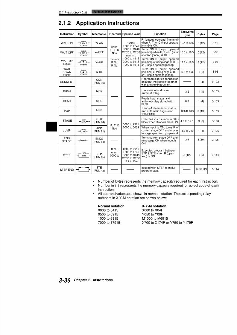
7/18/2019 Keyence Programming
http://slidepdf.com/reader/full/keyence-programming 60/392
2
• Number of bytes represents the memory capacity required fo
• Number in ( ) represents the memory capacity required for obinstruction.
• All operand values are shown in normal notation. The correspnumbers in X-Y-M notation are shown below:
Instruction Symbol Mnemonic Operand Operand value FunctionExec.tim
(µs)
WAIT ON
WAIT OFF
WAIT UPEDGE
WAITDOWNEDGE
CONNECT
PUSH
READ
POP
W-ON
W-OFF
W-UE
W-DE
CON(FUN 06)
MPS
MRD
MPP
nnnn:R, T, C
Nos.
mmmm:R No.R No.
17915T000 to T249C000 to C249CTC0 to CTC3
mmmm:1000 to 19153000 to 99151000 to 1915
10.4 to 12
13.6 to 18
13.6 to 18
6.8 to 5.
3.2
6.8
10.5 to 13
R (output operand [mmmm])when R, T, or C (input operand[nnnn]) is ON.
Turns ON R (output operand[mmmm]) at falling edge of R, T,or C (input operand [nnnn]).
Represents series connectionof output instruction togetherwith another instruction.
Stores input status andarithmetic flag.
Reads input status andarithmetic flag stored withPUSH.
STEP
STEP END
STP(FUN 45)
STE(FUN 43)
R No.nnnn:
0000 to
0500 to 9915T000 to T249C000 to C249CTC0 to CTC3
11.2 to 13.4
2.5
5 (12)
Reads & clears input statusand arithmetic flag storedwith PUSH.
Is used with STEP to makeprogram step.
STAGE
JUMP
ENDSTAGE
STG(FUN 44)
JMP(FUN 21)
ENDS(FUN 14)
R, T, CNos.
3000 to 99150000 to 0009
4.5 to 12
4.3 to 7.
Turns ON R (output operand[mmmm]) when R, T, or C (inputoperand [nnnn]) is OFF.
Turns ON R (output operand[mmmm]) at rising edge of R, T,or C (input operand [nnnn]).
Executes instructions in STGblock when R (operand) is ON.
When input is ON, turns R ofcurrent stage OFF and movesto stage specified by operand.
Turns current stage OFF andnext stage ON when input isON.
Executes program betweenSTP & STE when R (oper-and) is ON.
nnnnON
mmmm
nnnnOFF
mmmm
nnnn
mmmm
nnnn
mmmm
nnnn
STG
nnnn
J MP
ENDS
STPnnnn
STE
2.1 Instru
Instruction Symbol Mnemonic Operand Operand value Function
DMnnnn:
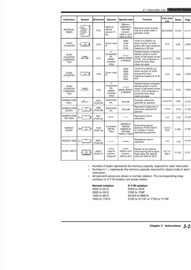
7/18/2019 Keyence Programming
http://slidepdf.com/reader/full/keyence-programming 61/392
INTERVAL
TIMER
16-BITCOUNTER
16-BITCOUNTERCOMPARA-
TOR
16-BITCOUNTER
16-BITCOUNTER
COMPARA-TOR
SUBROUTINECALL
ITVL
CTH
CTC
CALL(FUN 03)
SBN(FUN 38)
RET(FUN 33)
DMnnnn:DM No.
mmmm: RNo.
Count inputR
n:Comparator
No.ddddd:
# presetvalue
n:Comparator
No.
ddddd:# presetvalue
SubroutineNo.
DMnnnn:DM0000 to
DM1985mmmm:
1000 to 19123000 to 9912
0004210021012102
n: 0,1ddddd: #00001
to #65535
00050500220022012202
Measures pulse-to-pinterval & pulse width
specified mode.
16-bit (0 to 65535) udown counter for clopulses with input resfrequency of 30 kHz.
Hardware-based compbetween preset & currvalues of high-speed c(CTH0). This compara
turned ON when thesevalues are equal.
Executes subroutinespecified by operand
Represents beginninsubroutine specified operand.
Represents end ofsubroutine.
REPEATSTART
REPEAT END
16-KEY INPUT
FOR(FUN 16)
NEXT(FUN 29)
HKEY(FUN 17)
# constant,DM No.TMxx
nnnn:Input Rmmmm:Output R
#00000 to#65535
DM0000 toDM1999
TM00 to TM29
nnnn:0000 to 415mmmm:
0500 to 915
Executes programbetween FOR & NEfor number of timesspecified by operan
Represents end ofrepetition.
Reads 16-key data time-sharing and outhese data into specutility Rs 2900 to 29
SUBROUTINEENTRY
SUBROUTINERETURN
CTH
CTC
Count inputR
SubroutineNo.
n: 2,3ddddd: #00001
to #65535
00 to 99
00 to 99
16-bit (0 to 65535) udown counter for clopulses with inputresponse frequencykHz.
Hardware-based compbetween preset & currvalues of high-speed c
(CTH1). This comparaturned ON when thesevalues are equal.
ITVLPLSDMnnnnPAUSEmmmmRES
CTH0nnnn
CTCn#ddddd
CTH1nnnn
CTCn#ddddd
CALLnn
SBNnn
RET
FORnnnn
HKEYnnnn
mmmm
NEXT
2.1 Instruction List Visual KV Series
2.1.3 Arithmetic Instructions

7/18/2019 Keyence Programming
http://slidepdf.com/reader/full/keyence-programming 62/392
2
Instruction Symbol Mnemonic Operand Operand value FunctionExec.time
(µs)
DATAMEMORY
WRITE
TRIMMERSETTING
LOAD A
STORE A
COMPARE
ADD
DW
TMIN(FUN 50)
@TMIN@(FUN 50)
LDA(FUN 23)
@LDA@(FUN 23)
STA(FUN 42)
@STA@(FUN 42)
CMP(FUN 04)
@CMP@(FUN 04)
ADD(FUN00)
@ADD@(FUN 00)
SUB
nnnn:#/$ constantDMmmmm:
DM No.
Trimmer No.
R No.,C/T No.,DM No,TM xx,
#/$ constant,
#TMxx
R No.,C/T No.,DM No.,TM xx,
#TMxx
DM/TM No.TMxx,
#/$ constant,#TM
nnnn:#0000 to#65535
$0000 to$FFFF
DMmmmm:DM0000 to
DM1999
0 to 1
0000 to 17915T000 to T249C000 to C249CTH0 to CTH1
DM0000 toDM1999
TM00 to TM31#00000 to
#65535$0000 to $FFFF#TM00 to
#TM29
0500 to 19152100 to 17915T000 to T249C000 to C249
CTH0 toCTC3
DM0000 to
DM1999TM00 to TM29
#TM00 to#TM29
DM0000 toDM1999TM00 to TM31
#00000 to#65535
$0000 to$FFFF
8.0
8.9
20.9
6.4 to 14.0
18.4 to 26.0
6.6 to 28.5
18.0 to 40.5
10.8 to 35.6
22.8 to 47.6
9.4 to 34.2
21.4 to 46.2
10 8 to 35 6
Writes constant into datamemory.
Inputs value set byaccess window’s digital
trimmer (0 to 65535) tointernal register.
Inputs value specified byoperand into internalregister or inputs currentvalue when T/C is
specified as operand.
Transfers content ofinternal register tolocation specified byoperand, or changespreset value when T/C is
specified as operand.
Compares content ofinternal register andvalue specified byoperand.
Adds content of internalregister and valuespecified by operand andinputs result back tosame register.
Subtracts value specified
nnnn
DMmmmmDW
n TMIN
n TMIN
nnnnLDA
nnnnLDA
nnnnSTA
nnnnSTA
nnnnCMP
nnnnCMP
nnnn
ADD
nnnnADD
nnnnSUB
2.1 Instru
Instruction Symbol Mnemonic Operand Operand value Function
DM0000 to
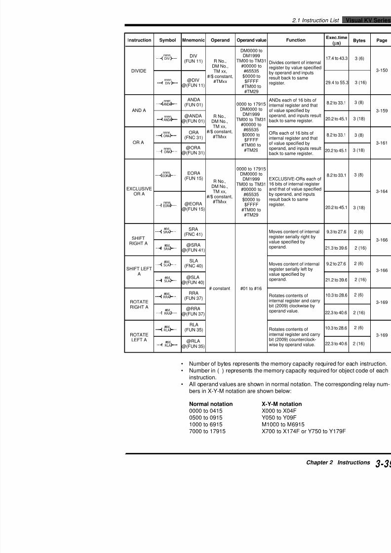
7/18/2019 Keyence Programming
http://slidepdf.com/reader/full/keyence-programming 63/392
@DIV@(FUN 11)
DIVIDE
DIV(FUN 11) Divides content of inter
register by value specifby operand and inputsresult back to sameregister.
R No.,
DM No.,TM xx,#/$ constant,
#TMxx
DM0000 toDM1999
TM00 to TM31
#00000 to#65535$0000 to$FFFF
#TM00 to#TM29
AND A
OR A
EXCLUSIVEOR A
SHIFTRIGHT A
SHIFT LEFTA
ROTATE
RIGHT A
ROTATE
ANDA(FUN 01)
@ANDA@(FUN 01)
ORA(FNC 31)
@ORA@(FUN 31)
EORA(FUN 15)
@EORA@(FUN 15)
SRA(FNC 41)
@SRA@(FUN 41)
SLA(FNC 40)
@SLA@(FUN 40)
RRA(FUN 37)
@RRA@(FUN 37)
RLA(FUN 35)
R No.,DM No.,
TM xx,#/$ constant,#TMxx
R No.,
DM No.,TM xx,
#/$ constant,#TMxx
# constant
0000 to 17915DM0000 to
DM1999TM00 to TM31
#00000 to#65535
$0000 to$FFFF
#TM00 to#TM29
0000 to 17915DM0000 to
DM1999TM00 to TM31
#00000 to#65535
$0000 to$FFFF
#TM00 to#TM29
ANDs each of 16 bits ointernal register and thaof value specified byoperand, and inputs resback to same register.
ORs each of 16 bits ofinternal register and thaof value specified byoperand, and inputs resback to same register.
EXCLUSIVE-ORs each16 bits of internal registand that of value specifby operand, and inputsresult back to sameregister.
Moves content of internregister serially left byvalue specified byoperand.
Rotates contents ofinternal register and ca
bit (2009) clockwise byoperand value.
Rotates contents ofinternal register and ca
Moves content of internregister serially right byvalue specified by
operand.
#01 to #16
nnnnDIV
nnnnDIV
nnnnANDA
nnnnANDA
nnnnORA
nnnnORA
nnnnEORA
nnnnEORA
#ddSRA
#ddSRA
#ddSLA
#ddSLA
#ddRRA
#ddRRA
#ddRLA
2.1 Instruction List Visual KV Series
Instruction Symbol Mnemonic OperandOperand
valueFunction
Exec.t(µs
COM
5 6

7/18/2019 Keyence Programming
http://slidepdf.com/reader/full/keyence-programming 64/392
2
Converts content ofinternal register (4-digitBCD) into 16-bit binarydata.
Converts content ofinternal register (16-bitbinary) into 4-digit BCDdata.
DEMULTI-PLEXER
TRANSFERBCD
TRANSFERBIN
ASCIICONVERT
REVERSEASCII
CONVERT
DMX
(FUN 12)
@DMX@(FUN 12)
TBCD(FUN 47)
@TBCD@(FUN 47)
TBIN(FUN 48)
@TBIN@(FUN 48)
ASC(FUN 02)
@ASC@(FUN 02)
RASC(FUN 32)
@RASC@(FUN 32)
22.6
34.6
5.6
17.6
9.6
21.6
9.7
21.
9.3
21.3
Converts position of
highest order bit with 1 ininternal register into 4-bitdata.
Converts content of lowerorder 8 bytes of internalregister into 2-digit ASCIIcode.
Converts 2-digit ASCIIcode of internal registerinto 2-digit numericalvalue.
T k t f 32
COMPLE-MENT
INCREMENTMEMORY
DECRE-
MENTMEMORY
MULTI-PLEXER
COM(FUN 05)
@COM@(FUN 05)
INC(FNC 19)
@INC@(FUN 19)
DEC(FNC 07)
@DEC@(FUN 07)
MPX(FUN 27)
@MPX@(FUN 27)
DM/TM No.
DM/TM No.
DM0000 toDM1999TM00 to
TM29
5.6
17.6
9.8
21.8
10.4
22.4
10.1
22.1
Inverts content of each bitin internal register.
Adds 1 to content of datamemory specified byoperand.
Subtracts 1 from content
of data memory specifiedby operand.
Converts 4-bit data(specified by operand) ofinternal register into 16-bitdata.
# constant
DM0000 to
DM1999TM00 toTM29
#0 to #3
COM
COM
nnnnINC
nnnnINC
nnnnDEC
nnnnDEC
#nMPX
#nMPX
DMX
DMX
TBCD
TBCD
TBIN
TBIN
ASC
ASC
RASC
RASC
2.1 Instru
2.1.4 Interrupt Instructions
Instruction Symbol Mnemonic Operand Operand value Function
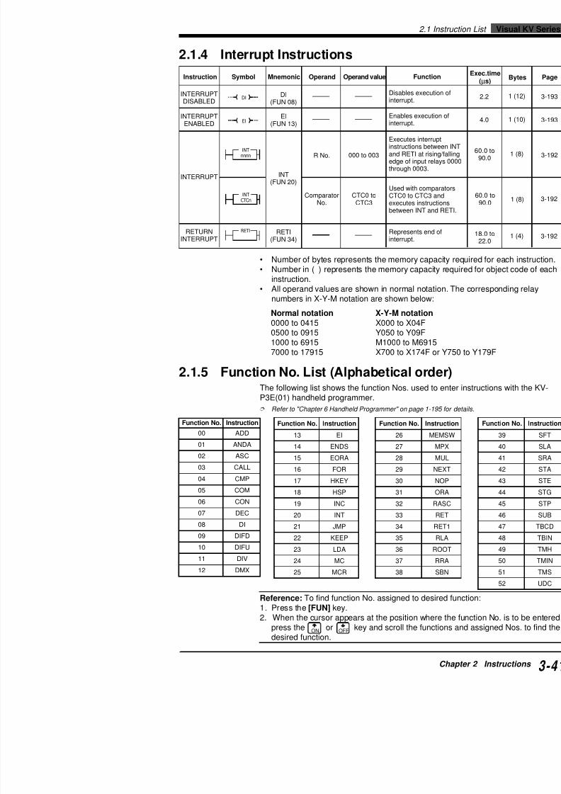
7/18/2019 Keyence Programming
http://slidepdf.com/reader/full/keyence-programming 65/392
• Number of bytes represents the memory capacity
• Number in ( ) represents the memory capacity reqinstruction.
• All operand values are shown in normal notation. Tnumbers in X-Y-M notation are shown below:
Normal notation X-Y-M notation0000 to 0415 X000 to X04F0500 to 0915 Y050 to Y09F1000 to 6915 M1000 to M6915
7000 to 17915 X700 to X174F or Y75
2.1.5 Function No. List (Alphabetical order)The following list shows the function Nos. used to enteP3E(01) handheld programmer.
Refer to "Chapter 6 Handheld Programmer" on page 1-195 for
Instruction Symbol Mnemonic Operand Operand value Function
INTERRUPTDISABLED
INTERRUPTENABLED
INTERRUPT
RETURNINTERRUPT
DI(FUN 08)
EI(FUN 13)
INT
(FUN 20)
RETI(FUN 34)
R No.
ComparatorNo.
000 to 003
CTC0 toCTC3
Disables execution of
interrupt.
Enables execution ofinterrupt.
Executes interruptinstructions between Iand RETI at rising/falliedge of input relays 00through 0003.
Used with comparatorCTC0 to CTC3 andexecutes instructionsbetween INT and RET
Represents end ofinterrupt.
DI
EI
INTnnnn
INTCTCn
RETI
.oNnoitcnuF noitcurtsnI
00 DDA
10 ADNA
20 CSA
30 LLAC
40 PMC
.oNnoitcnuF oitcurtsnI
62 WSMEM
72 XPM
82 LUM
92 TXEN
03 PON
.oNnoitcnuF noitcurtsnI
31 IE
41 SDNE
51 AROE
61 ROF
71 YEKH
KV-300 Series, KV-10/802.2 Instruction List
KV-300 Series,
2.2 Instruction List• Number of bytes represents the memory capacity required fo
KV-300 Series, KV-10/80
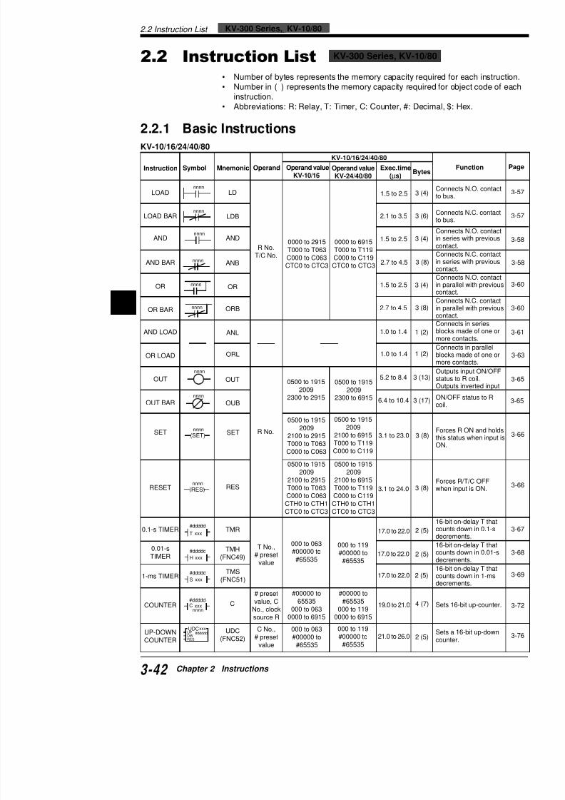
7/18/2019 Keyence Programming
http://slidepdf.com/reader/full/keyence-programming 66/392
2
Number of bytes represents the memory capacity required fo• Number in ( ) represents the memory capacity required for ob
instruction.• Abbreviations: R: Relay, T: Timer, C: Counter, #: Decimal, $:
2.2.1 Basic Instructions
KV-10/16/24/40/80
nnnnLOAD
nnnn
nnnn
nnnn
nnnn
nnnn
nnnn
nnnn
(SET)nnnn
LD
R No.T/C No.
LOAD BAR LDB
AND AND
AND BAR ANB
OR OR
OR BAR ORB
AND LOAD ANL
OR LOAD ORL
OUT OUT
R No.
OUT BAR OUB
SET SET
RESET RES
0000 to 2915T000 to T063C000 to C063CTC0 to CTC3
0500 to 19152009
2300 to 2915
0500 to 19152009
2100 to 2915
T000 to T063C000 to C063
0500 to 19152009
2100 to 2915T000 to T063(RES)
nnnn
0000 to 6915T000 to T119C000 to C119CTC0 to CTC3
0500 to 19152009
2300 to 6915
0500 to 19152009
2100 to 6915
T000 to T119C000 to C119
0500 to 19152009
2100 to 6915T000 to T119
1.5 to 2.5
2.1 to 3.5
1.5 to 2.5
2.7 to 4.5
1.5 to 2.5
2.7 to 4.5
1.0 to 1.4
1.0 to 1.4
5.2 to 8.4
6.4 to 10.4
3.1 to 23.0
3 1 to 24 0
3 (4)
3 (6)
3 (4)
3 (8)
3 (4)
3 (8)
1 (2)
1 (2)
3 (13)
3 (17)
3 (8)
3 (8)
Connecto bus.
Connecto bus.
Connecin seriecontact
Connecin serie
contactConnecin paracontact
Connecin paracontact
Connecblocks more c
Connec
blocks more c
Outputstatus tOutput
ON/OFcoil.
Forcesthis sta
ON.
Forceswhen in
KV-10/16/24/40/80
Instruction Symbol Mnemonic Operand Operand valueKV-10/16
Operand valueKV-24/40/80
Exec.time(µs)
Bytes
2.2 Instruction List
KV-10/16/24/40/80
Instruction Symbol Mnemonic Operand Operand valueKV-10/16
Operand valueKV-24/40/80
Exec.time(µs)
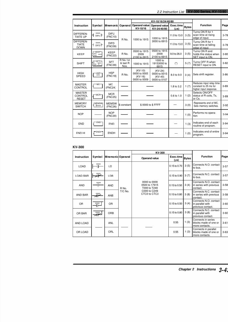
7/18/2019 Keyence Programming
http://slidepdf.com/reader/full/keyence-programming 67/392
KV-300
Instruction Symbol Mnemonic OperandOperand value
Exec.time(µs)
LOADnnnn
nnnn
nnnn
nnnn
LOAD BAR
AND
AND BAR
LD
LDB
AND
ANB
R No.T/C No.
0000 to 00090500 to 17915T000 to T249C000 to C249CTC0 to CTC3
0.15 to 0.70
0.15 to 0.90
0.15 to 0.50
0.15 to 0.80
KV-300
nnnn
DIFU
nnnn
DIFD
KEEPSET
RES nnnn
SFTDCLKRES
nnnn
mmmm
MC
HSPnnnn
MCR
$xxxx
MEMSW$xxxx
END
ENDH
DIFFEREN-TIATE UP
DIFU(FNC10)
R No.DIFFEREN-TIATEDOWN
DIFD(FNC09)
KEEPKEEP
(FNC22)R No.
SHIFTSFT
(FNC39)
R No.1st& last R
Nos.
HIGHSPEED
HSP(FNC18) R No.
MASTERCONTROL
MC(FNC24)
MASTERCONTROL
RESET
MCR(FNC25)
MEMORYSWITCH
MEMSW(FNC26)
$ constant
NOP NOP(FNC30)
END END
END HI ENDH
1000 to 1915
0500 to 19152009
2100 to 2915
1000 to 1915
(KV-10)
0000 to 0005(KV-16)0000 to 0009
$ 0000 to $ FFFF
1000 to 19153000 to 6915
0500 to 19152009
2100 to 6915
1000 to19153000 to
6915
(KV-24)
0000 to 0015(KV-40)0000 to 0107
11.0 to 13.0
11.0 to 13.0
9.0 to 26.0
(*)
8.0 to 9.0
1.8 to 3.2
0.6 to 1.0
––
––
––
––
KV-300 Series, KV-10/802.2 Instruction List
KV-300 Series,
KV-300
Instruction Symbol Mnemonic Operand Operand value Exec.time(µs)
Bytes
nnnn

7/18/2019 Keyence Programming
http://slidepdf.com/reader/full/keyence-programming 68/392
2
OUT
OUT BAR
nnnn
nnnn
(SET)nnnn
(RES)nnnn
#ddddd
T xxx
#ddddd
xxxH
#ddddd
xxxS
nnnn
#dddddC xxx
UDCxxx#dddddUP
DWRES
nnnn
DIFU
nnnn
DIFD
KEEPSET
RES nnnn
SFTDCLK
RES
nnnn
mmmm
HSPnnnn
SET
RESET
0.1-s TIMER
0.01-s TIMER
1-ms TIMER
COUNTER
UP-DOWNCOUNTER
DIFFEREN-TIATE UP
DIFFEREN-TIATE DOWN
KEEP
SHIFT
HIGHSPEED
OUT
OUB
SET
RES
TMR
TMH(FNC49)
TMS(FNC51)
C
UDC(FNC52)
DIFUFNC10)
DIFD(FNC09)
KEEP(FNC22)
SFT
(FNC39)
HSP(FNC18)
R No.
T No.,# preset
value
# presetvalue, CNo., clocksource R
C No.,# presetvalue
R No.
R No.
1st &last R
Nos.
R No.
0500 to 1915
20092300 to 17915
0500 to 19152009
2100 to 17915T000 to T249C000 to C249
0500 to 1915
20092100 to 17915T000 to T249C000 to C249CTH0 to CTH1CTC0 to CTC3
000 to 249#00000 to 65535
#00000 to #65535000 to 249
0000 to 00090500 to 17915
000 to 249#00000 to #65535
1000 to 19153000 to 6915
(*) 7000 to 9915
0500 to 19152009
2100 to 17915
1000 to 19153000 to 6915
(*) 7000 to 9915
0000 to 0009
0.20 to 0.56
0.50 to 1.20
0.20 to 5.70
0.50 to 4.40
5.60 to 10.40
5.60 to 10.40
5.60 to 10.40
7.60 to 9.45
8.00 to 11.60
6.70
6.70
6.10 to 7.90
6.40 to 8.20
4.66 to 4.92
3 (8)
3 (11)
3 (12)
3 (12)
2 (7)
2 (7)
2 (7)
4 (7)
2 (10)
3 (10)
3 (10)
3 (11)
5 (15)
3 (8)
Outpustatus
OutputON/OFcoil.
Forcesthis stais ON.
Forceswhen
16-bit countsdecrem
16-bit counts
decrem16-bit countsdecrem
Sets 1
Sets acounte
Turns time ainput.Turns time ainput.
Turns this stainput is
Turns
RESE
Sets s
Reduce
2.2 Instruction List
2.2.2 Application Instructions
KV-10/16/24/40/80

7/18/2019 Keyence Programming
http://slidepdf.com/reader/full/keyence-programming 69/392
KV-10/16/24/40/80
Instruction Symbol Mnemonic Operand Operand valueKV-10/16 Operand valueKV-24/40/80
Exec.time(µs) Byte
WAIT ON
WAIT OFF
WAIT UPEDGE
WAIT DOWNEDGE
CONNECT
PUSH
READ
POP
STAGE
JUMP
END
STAGE
STEP
STEP END
INTERVALTIMER
8-BITCOUNTER
8 BIT
W-ONnnnnON
mmmm
W-OFFnnnnOFF
mmmm
W-UE
W-D
CON[FNC 06]
MPS
MRD
MPP
STG[FNC 44]
JMP[FNC 21]
ENDS
[FNC 14]
STP[FNC 45]
STE[FNC 43]
ITVL
CTH
nnnn:R,T, or C
No.
R No.
R, T, CNos.
DM & RNo.
Clocksource Rs
n:
nnnn↑
mmmm
nnnn↓
mmmm
nnnn
STG
nnnnJMP
ENDS
STPnnnn
STE
ITVLPLS
PAUSERES
nnnnmmmmDM
nnnnCTH0
nnnn:0000 to 2915T000 to T063C000 to C063CTC0 to CTC3
mmmm:1000 to 1915
1000 to 1915
0000 to 2915T000 to T063C000 to C063CTC0 to CTC3
DM0000 to
DM09851000 to 1912
00042100 to 2102
nnnn:0000 to 6915T000 to T119C000 to C119CTC0 to CTC3
mmmm:1000 to 1915
3000 to 6915
1000 to 19153000 to 6915
0000 to 6915T000 to T119C000 to C119CTC0 to CTC3
DM0000 toDM1985
1000 to 19123000 to 6912
11.0 to13.0
11.0 to13.0
14.0 to18.0
14.0 to18.0
0.4 to0.6
11.0 to14.0
8.0 to10.0
10.0 to12.0
11.0 to14.0
10.0 to13.0
7.0 to
9.0
3.7 to5.3
0.00
29.0 to
79.0
9.0 to39.0
5 (7
5 (7
5 (7
5 (7
30
1 (3
1 (3
1 (3
3 (7
3 (5
1 (3
3 (7
1 (0
5 (7
4 (4
KV-300 Series, KV-10/802.2 Instruction List
KV-300 Series,
KV-10/16/24/40/80
Instruction Symbol Mnemonic Operand Operand valueKV-10/16
Operand valueKV-24/40/80
Exec.time(µs)
Bytes
#00000 to #00000 to

7/18/2019 Keyence Programming
http://slidepdf.com/reader/full/keyence-programming 70/392
2
KV-300
KV-300
Instruction Symbol Mnemonic Operand Operand value Exec.time(µs)
BytesF
WAIT ONnnnn
ON
mmmm
nnnnOFF
mmmm
nnnn
↑mmmm
nnnn↓
mmmm
nnnn
STG
nnnnJMP
WAIT OFF
WAIT UPEDGE
WAIT DOWNEDGE
CONNECT
PUSH
READ
POP
STAGE
JUMP
W-ON
W-OFF
W-UE
W-DE
CON[FNC 06]
MPS
MRD
MPP
STG[FNC 44]
JMP[FNC 21]
nnnn:R,T, orC No.
R No.
nnnn:
0000 to 00090500 to 17915T000 to T249C000 to C249CTC0 to CTC3
mmmm:1000 to 19153000 to 6915
(*)7000 to 9915
1000 to 19153000 to 6915
(*)7000 to 9915
5.00 to 6.10
5.00 to 6.10
6.10 to 7.50
6.10 to 7.50
—
1.30
2.70
1.40
5.60 to 6.50
3.80 to 6.00
5 (9)
5 (9)
5 (10)
5 (10)
1 (0)
1 (9)
1 (18)
1 (9)
3 (10)
3 (7)
Turns ON [mmmm])
operand [nWhen R, T[nnnn]) turoperand [m
R (2nd opturns ON T, or C (1s
R (2nd opturns ON T, or C (1s
Represenof output iwith anoth
Stores inparithmetic
Reads inparithmeticPUSH.
Reads & cand arithmwith PUSH
Executes between S(operand)
Turns curnext stageON.
REPEAT
START
REPEATEND
16-KEYINPUT
FOR
[FNC 16]
NEXT[FNC 29]
HKEY[FNC 17]
# constant,
DM No.
I/O R
nnnn
FOR
NEXT
nnnnmmmm
HKEY
#00000 to#65535
DM0000 toDM0999TM00 to TM29
nnnn:0000 to 000910000 to 10415
:17000 to 17415
mmmm:10500 to 10915:17500 to 17915
#00000 to#65535
DM0000 toDM1999TM00 to TM29
5.0 to 20.0
1.7 to 2.3
71 to 370
3 (15)
1 (3)
5 (7)
Execbetwfor nuspec
Reprrepet
Readtimeoutpspecto 29
2.2 Instruction List
KV-300
Instruction Symbol Mnemonic OperandOperand value
Exec.time(µs)
Byt
n:
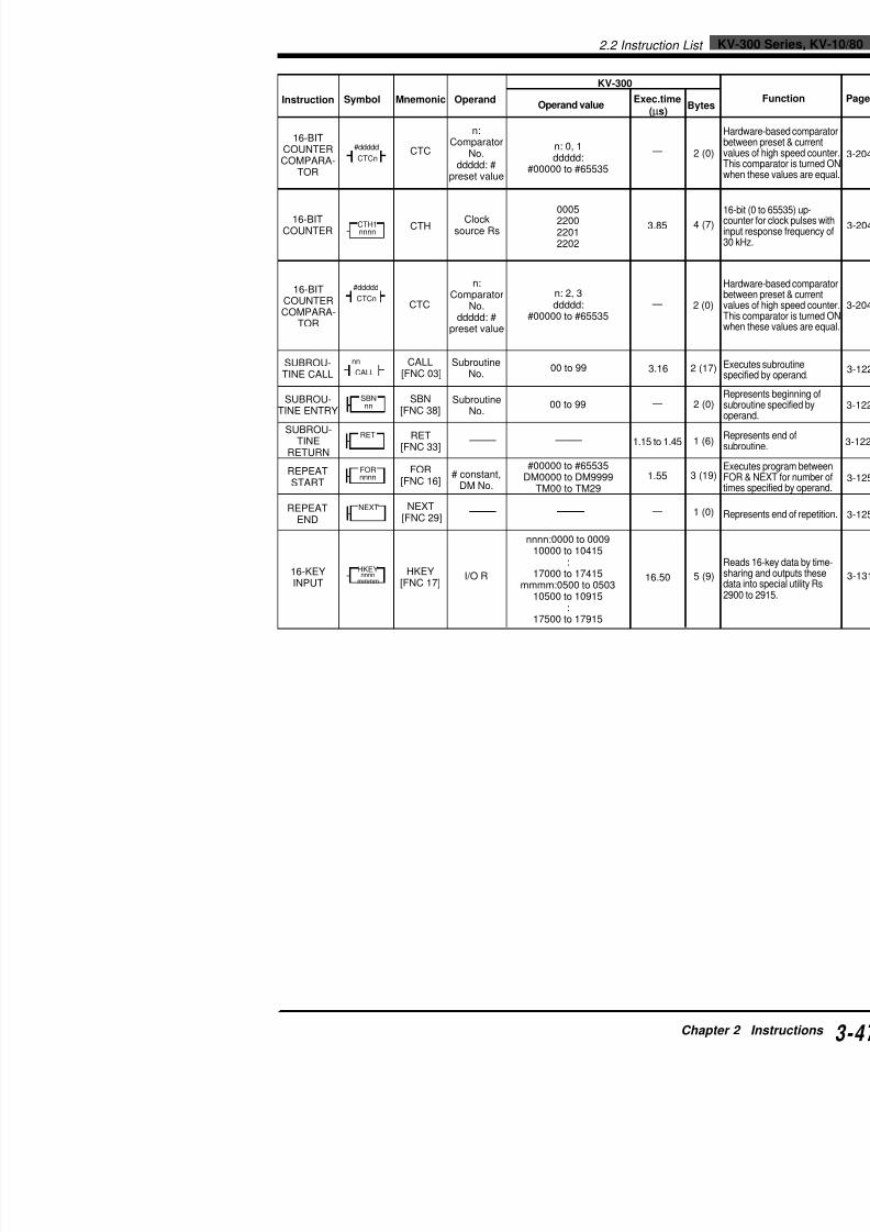
7/18/2019 Keyence Programming
http://slidepdf.com/reader/full/keyence-programming 71/392
16-BITCOUNTERCOMPARA-
TOR
16-BITCOUNTER
16-BITCOUNTERCOMPARA-
TOR
SUBROU-TINE CALL
SUBROU-TINE ENTRY
SUBROU-TINE
RETURN
REPEATSTART
REPEATEND
16-KEYINPUT
CTC
CTH
CTC
SBN[FNC 38]
RET[FNC 33]
FOR[FNC 16]
NEXT [FNC 29]
HKEY[FNC 17]
CALL [FNC 03]
#ddddd
CTCn
nnnnCTH1
#dddddCTCn
nn
CALL
nnSBN
RET
nnnnFOR
NEXT
nnnnmmmm
HKEY
n:Comparator
No.ddddd: #
preset value
Clocksource Rs
n:ComparatorNo.
ddddd: #preset value
SubroutineNo.
SubroutineNo.
# constant,DM No.
I/O R
n: 0, 1
ddddd:#00000 to #65535
0005220022012202
n: 2, 3ddddd:
#00000 to #65535
00 to 99
00 to 99
#00000 to #65535DM0000 to DM9999
TM00 to TM29
nnnn:0000 to 0009
10000 to 10415:
17000 to 17415mmmm:0500 to 0503
10500 to 10915:
17500 to 17915
—
3.85
—
3.16
—
1.15 to 1.45
1.55
—
16.50
2
4
2
2 (
2
1
3 (
1
5
KV-300 Series, KV-10/802.2 Instruction List
KV-300 Series,
2.2.3 Arithmetic Instructions
KV-10/16/24/40/80
KV-10/16/24/40/80
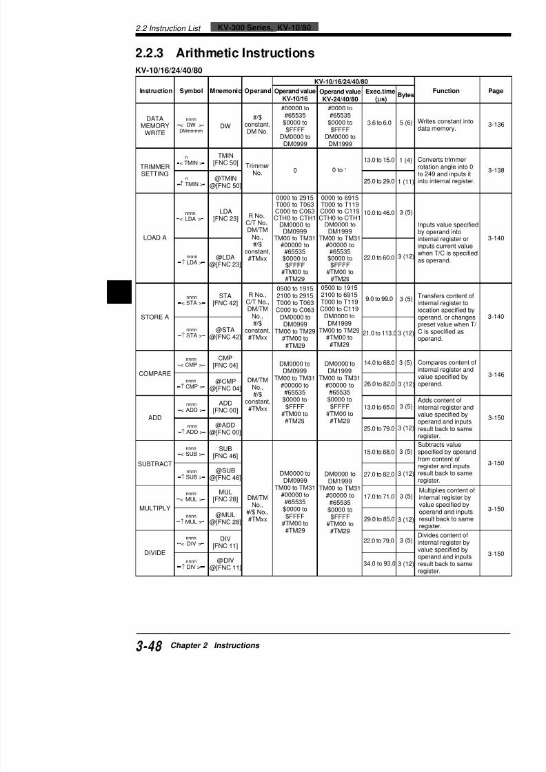
7/18/2019 Keyence Programming
http://slidepdf.com/reader/full/keyence-programming 72/392
2
KV 10/16/24/40/80
Instruction Symbol Mnemonic Operand Operand value
KV-10/16
Operand value
KV-24/40/80
Exec.time
(µs) Bytes
Fu
DATAMEMORY
WRITE
TRIMMERSETTING
LOAD A
STORE A
COMPARE
ADD
SUBTRACT
DW
TMIN[FNC 50]
@TMIN@[FNC 50]
LDA[FNC 23]
@LDA
@[FNC 23]
STA[FNC 42]
@STA@[FNC 42]
CMP[FNC 04]
@CMP@[FNC 04]
ADD[FNC 00]
@ADD@[FNC 00]
SUB[FNC 46]
@SUB
#/$constant,DM No.
TrimmerNo.
R No.,C/T No.,DM/TM
No.,#/$
constant,#TMxx
R No.,C/T No.,DM/TM
No.,#/$
constant,#TMxx
DM/TMNo.,#/$
constant,#TMxx
#00000 to#65535$0000 to$FFFF
DM0000 toDM0999
0
0000 to 2915T000 to T063C000 to C063CTH0 to CTH1
DM0000 toDM0999
TM00 to TM31#00000 to
#65535$0000 to$FFFF
#TM00 to#TM29
0500 to 19152100 to 2915T000 to T063C000 to C063
DM0000 toDM0999
TM00 to TM29#TM00 to
#TM29
DM0000 toDM0999
TM00 to TM31#00000 to
#65535$0000 to$FFFF
#TM00 to#TM29
DM0000
#0000 to#65535
$0000 to$FFFF
DM0000 toDM1999
0 to 1
0000 to 6915T000 to T119C000 to C119CTH0 to CTH1
DM0000 toDM1999
TM00 to TM31#00000 to
#65535$0000 to$FFFF
#TM00 to#TM29
0500 to 19152100 to 6915T000 to T119C000 to C119
DM0000 toDM1999
TM00 to TM29#TM00 to
#TM29
DM0000 toDM1999
TM00 to TM31#00000 to
#65535$0000 to$FFFF
#TM00 to#TM29
3.6 to 6.0
13.0 to 15.0
25.0 to 29.0
10.0 to 46.0
22.0 to 60.0
9.0 to 99.0
21.0 to 113.0
14.0 to 68.0
26.0 to 82.0
13.0 to 65.0
25.0 to 79.0
15.0 to 68.0
5 (6)
1 (4)
1 (11)
3 (5)
3 (12)
3 (5)
3 (12)
3 (5)
3 (12)
3 (5)
3 (12)
3 (5)
3 (12)
Writes cdata me
Convertrotation to 249 a
into inte
Inputs vby operainternal inputs cuwhen T/
as opera
Transferinternal location operandpreset vC is speoperand
Comparinternal value spoperand
Adds cointernal value spoperand
result baregister.
Subtractspecifiedfrom conregister
lt b
< DW >DMmmmm
nnnn
< TMIN >n
↑ TMIN >n
< LDA >nnnn
↑ LDA >
nnnn
< STA >nnnn
↑ STA >nnnn
< CMP >nnnn
↑ CMP >nnnn
< ADD >nnnn
↑ ADD >nnnn
<
SUB
>nnnn
nnnn
2.2 Instruction List
KV-10/16/24/40/80
Instruction Symbol Mnemonic Operand Operand valueKV-10/16
Operand valueKV-24/40/80
Exec.time(µs)
ANDA[FNC ] 0000 to 2915 0000 to 6915 11 0 to 64 0ANDA
nnnn
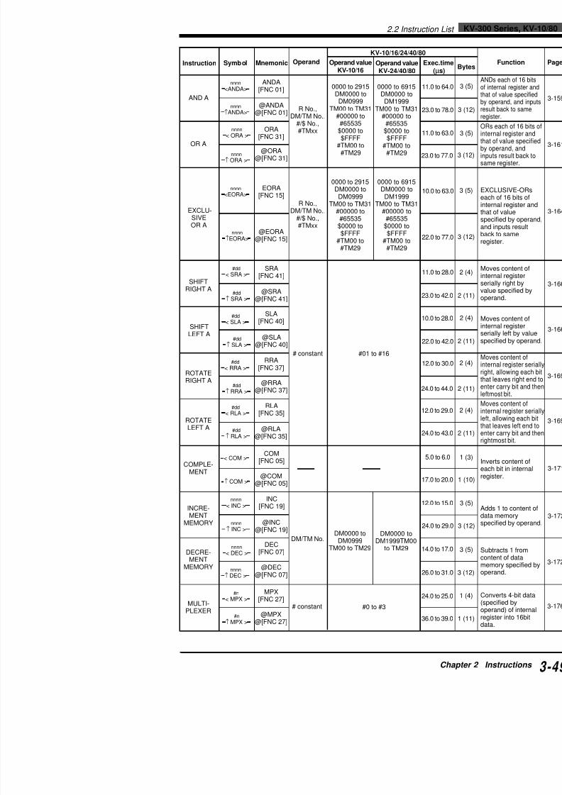
7/18/2019 Keyence Programming
http://slidepdf.com/reader/full/keyence-programming 73/392
AND A
OR A
EXCLU-SIVEOR A
SHIFTRIGHT A
SHIFTLEFT A
ROTATERIGHT A
ROTATELEFT A
COMPLE-MENT
[FNC 01]
@ANDA@[FNC 01]
ORA[FNC 31]
@ORA@[FNC 31]
EORA[FNC 15]
@EORA@[FNC 15]
SRA[FNC 41]
@SRA@[FNC 41]
SLA[FNC 40]
@SLA@[FNC 40]
RRA[FNC 37]
@RRA@[FNC 37]
RLA[FNC 35]
@RLA@[FNC 35]
COM[FNC 05]
@COM@[FNC 05]
R No.,DM/TM No.,
#/$ No.,#TMxx
R No.,DM/TM No.,
#/$ No.,#TMxx
# constant
0000 to 2915DM0000 to
DM0999TM00 to TM31
#00000 to#65535
$0000 to$FFFF
#TM00 to#TM29
0000 to 2915DM0000 to
DM0999TM00 to TM31
#00000 to#65535
$0000 to$FFFF
#TM00 to#TM29
#01 to #16
0000 to 6915DM0000 to
DM1999TM00 to TM31
#00000 to#65535
$0000 to$FFFF
#TM00 to#TM29
0000 to 6915DM0000 to
DM1999TM00 to TM31
#00000 to#65535
$0000 to$FFFF
#TM00 to#TM29
11.0 to 64.0
23.0 to 78.0
11.0 to 63.0
23.0 to 77.0
10.0 to 63.0
22.0 to 77.0
11.0 to 28.0
23.0 to 42.0
10.0 to 28.0
22.0 to 42.0
12.0 to 30.0
24.0 to 44.0
12.0 to 29.0
24.0 to 43.0
5.0 to 6.0
17.0 to 20.0
<ANDA>
↑ANDA>nnnn
< ORA >nnnn
↑ ORA >nnnn
<EORA>nnnn
↑EORA>nnnn
< SRA >#dd
↑ SRA >#dd
< SLA >#dd
↑ SLA >#dd
< RRA >#dd
↑ RRA >#dd
< RLA >#dd
↑ RLA >#dd
< COM >
↑ COM >
KV-300 Series, KV-10/802.2 Instruction List
KV-300 Series,
KV-10/16/24/40/80
Instruction Symbol Mnemonic Operand Operand valueKV-10/16
Operand valueKV-24/40/80
Exec.time(µs)
Bytes
DMX[FNC 12] 28 0 to 30 0 1 (3) Conve
< DMX >

7/18/2019 Keyence Programming
http://slidepdf.com/reader/full/keyence-programming 74/392
2
KV-300
Instruction Symbol Mnemonic Operand Operand valueExec.time
(µs)Bytes
KV-300
DATAMEMORY
WRITE
TRIMMERSETTING
DW
TMIN [FNC 50]
@TMIN@[FNC 50]
#/$constant,DM No.
TrimmerNo.
nnnn:#0000 to #65535$0000 to $FFFF
DMmmmm:DM0000 to DM9999
0, 1
0.60 to1.40
5.10 to5.60
2.00 to5.70
5 (11)
1 (11)
1 (25)
Writes data m
Converotation249 aninterna
< DW >DMmmmm
nnnn
< TMIN >n
↑ TMIN >n
DEMULTI-PLEXER
TRANSFERBCD
TRANSFERBIN
ASCIICONVERT
REVERSEASCII
CONVERT
SQUAREROOT
[FNC 12]
@DMX@[FNC 12]
TBCD[FNC 47]
@TBCD@[FNC 47]
TBIN[FNC 48]
@TBIN@[FNC 48]
ASC[FNC 02]
@ASC@[FNC 02]
RASC[FNC 32]
@RASC@[FNC 32]
ROOT[FNC 36]
@ROOT@[FNC 36]
28.0 to 30.0
40.0 to 44.0
19.0 to 21.0
31.0 to 35.0
18.0 to 20.0
30.0 to 34.0
8.0
20.0 to 22.0
12.0 to 14.0
24.0 to 28.0
102.0 to103.0
114.0 to117.0
1 (3)
1 (10)
1 (3)
1 (10)
1 (3)
1 (10)
1 (3)
1 (10)
1 (3)
1 (10)
1 (3)
1 (10)
Convehighes
1 in intinto 4-
Conveinternabit binBCD d
Conve
internadigit Bbinary
Convelower interna2-digit
Convecode idata.
Takes bit dataorder bregistebyte) aback to
< DMX >
↑ DMX >
<TBCD>
↑ TBCD>
< TBIN >
↑ TBIN>
< ASC >
↑ ASC >
<RASC>
↑ RASC>
<ROOT>
↑ ROOT>
2.2 Instruction List
KV-300
Instruction Symbol Mnemonic Operand Operand valueExec.time
(µs)B
CMP 9.20 to3< CMP >
nnnn

7/18/2019 Keyence Programming
http://slidepdf.com/reader/full/keyence-programming 75/392
COMPARE
ADD
SUBTRACT
MULTIPLY
DIVIDE
AND A
OR A
EXCLUSIVEOR A
[FNC 04]
@CMP@[FNC 04]
ADD[FNC 00]
@ADD@[FNC 00]
SUB
[FNC 46]
@SUB@[FNC 46]
MUL [FNC 28]
@MUL@[FNC 28]
DIV[FNC 11]
@DIV@[FNC 11]
ANDA[FNC 01]
@ANDA@[FNC 01]
ORA [FNC 31]
@ORA@[FNC 31]
EORA[FNC 15]
@EORA
@[FNC 15]
DM/TMNo.,#/$
constant,#TMxx
DM/TMNo.,
#/$ No.,#TMxx
R No.,DM/TM
No.,#/$ No.,#TMxx
R No.,DM/TM
No.,#/$ No.,
#TMxx
DM0000 to DM9999TM00 to TM31
#00000 to #65535$0000 to $FFFF#TM00 to #TM29
DM0000 to DM9999TM00 to TM31
#00000 to #65535$0000 to $FFFF#TM00 to #TM29
0000 to 00090500 to 17915
DM0000 to DM9999
TM00 to TM31#00000 to #65535$0000 to $FFFF#TM00 to #TM29
0000 to 00090500 to 17915
DM0000 to DM9999TM00 toTM31
#00000 to #65535$0000 to $FFFF
#TM00 to #TM29
36.00
11.20 to38.00
7.70 to35.00
9.70 to37.00
8.40 to
35.00
10.40 to37.00
9.80 to37.00
11.80 to39.00
13.70 to41.00
15.70 to42.00
6.90 to33.00
8.90 to35.00
6.90 to33.00
8.90 to35.00
6.90 to33.00
8.9 to
35.00
3
3
3
3
3
3
3
3
3
3
3
3
3
3
3
3
< CMP >
↑ CMP >nnnn
< ADD >nnnn
↑ ADD >nnnn
< SUB >nnnn
↑ SUB >nnnn
< MUL >nnnn
↑ MUL >nnnn
<
DIV
>nnnn
↑ DIV >nnnn
<ANDA>nnnn
↑ANDA>nnnn
< ORA >nnnn
↑ ORA >nnnn
<EORA>nnnn
↑EORA>nnnn
KV-300 Series, KV-10/802.2 Instruction List
KV-300 Series,
KV-300
Instruction Symbol Mnemonic Operand Operand valueExec.time
(µs)Bytes
SRA[FNC 41]
10.80 2 (22) Moves c< SRA >#dd

7/18/2019 Keyence Programming
http://slidepdf.com/reader/full/keyence-programming 76/392
2
SHIFT
RIGHT A
SHIFTLEFT A
ROTATERIGHT A
ROTATELEFT A
COMPLE-MENT
INCREMENTMEMORY
DECREMENTMEMORY
MULTI-PLEXER
DEMULTI-PLEXER
[FNC 41]
@SRA@[FNC 41]
SLA[FNC 40]
@SLA@[FNC 40]
RRA
[FNC 37]
@RRA@[FNC 37]
RLA [FNC 35]
@RLA@[FNC 35]
COM [FNC 05]
@COM@[FNC 05]
INC[FNC 19]
@INC@[FNC 19]
DEC[FNC 07]
@DEC@[FNC 07]
MPX [FNC 27]
@MPX@[FNC 27]
DMX [FNC 12]
@DMX@[FNC 12]
# constant
DM/TMNo.
# constant
#01 to #16
DM0000 to DM9999TM00 to TM29
#0 to #3
10.80
12.80
10.80
12.80
12.00
14.00
12.00
14.00
6.10
8.10
7.70
9.70
7.70
9.70
7.30
9.30
6.70
8.70
( )
2 (25)
2 (11)
2 (25)
2 (11)
2 (25)
2 (11)
2 (25)
1 (9)
1 (23)
3 (12)
3 (26)
3 (12)
3 (26)
1 (11)
1 (25)
1 (9)
1 (23)
internal
right by by oper
Moves cinternal left by voperand
Moves cinternal
right, althat leaventer caleftmost
Moves internaleft, allothat leaenter carightmo
Inverts cbit in int
Adds 1 data meby oper
Subtracof data specifie
Convert(specifieof intern16- bit d
Converthighest in intern4-bit da
< SRA >
↑ SRA >#dd
< SLA >#dd
↑ SLA >#dd
< RRA >
#dd
↑ RRA >#dd
< RLA >#dd
↑ RLA >#dd
< COM >
↑ COM >
< INC >nnnn
↑ INC >nnnn
< DEC >nnnn
↑ DEC >nnnn
< MPX >#n
↑ MPX >#n
< DMX >
↑ DMX >
2.2 Instruction List
KV-300
Instruction Symbol Mnemonic Operand Operand value Exec.time(µs)
By
TBCD[FNC 47]
13.20 1<TBCD>
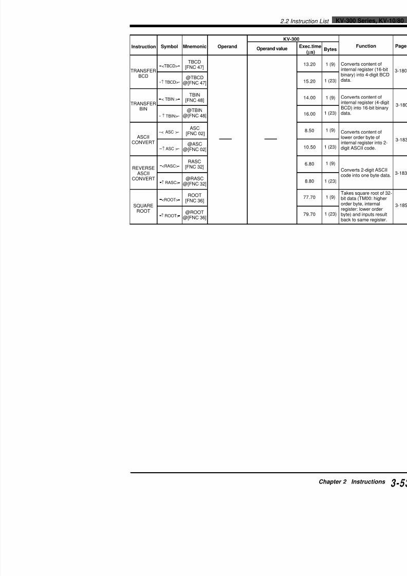
7/18/2019 Keyence Programming
http://slidepdf.com/reader/full/keyence-programming 77/392
TRANSFERBCD
TRANSFERBIN
ASCIICONVERT
REVERSEASCII
CONVERT
SQUAREROOT
[FNC 47]
@TBCD@[FNC 47]
TBIN[FNC 48]
@TBIN@[FNC 48]
ASC
[FNC 02]
@ASC@[FNC 02]
RASC[FNC 32]
@RASC@[FNC 32]
ROOT[FNC 36]
@ROOT@[FNC 36]
15.20
14.00
16.00
8.50
10.50
6.80
8.80
77.70
79.70
1
1
1
1
1
1
1
1
1
<TBCD>
↑ TBCD>
< TBIN >
↑ TBIN>
< ASC >
↑ ASC >
<RASC>
↑ RASC>
<ROOT>
↑ ROOT>
KV-300 Series, KV-10/802.2 Instruction List
KV-300 Series,
2.2.4 Interrupt Instructions
KV-10/16/24/40/80
KV-10/16/24/40/80
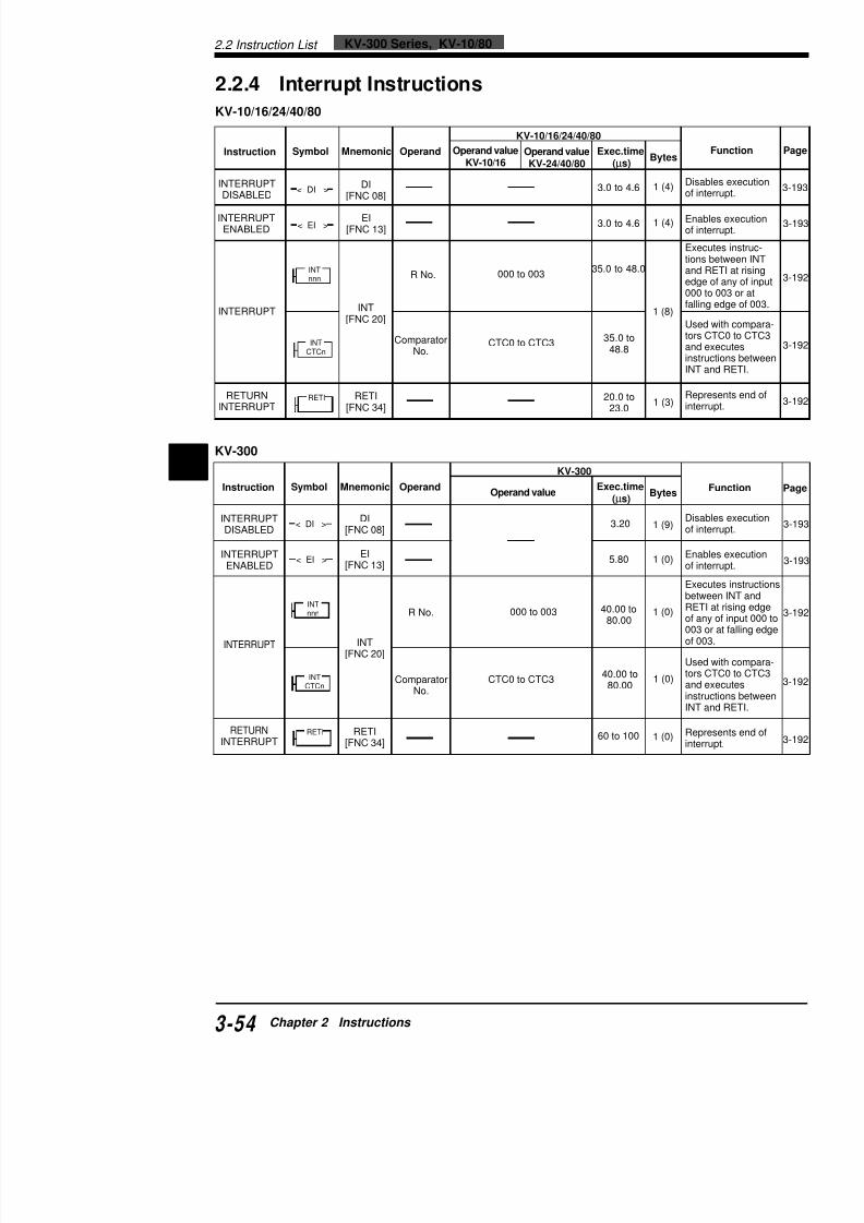
7/18/2019 Keyence Programming
http://slidepdf.com/reader/full/keyence-programming 78/392
2 KV-300
Instruction Symbol Mnemonic OperandOperand value
Exec.time(µs)
Bytes
INTERRUPTDISABLED
INTERRUPTENABLED
INTERRUPT
RETURNINTERRUPT
DI[FNC 08]
EI[FNC 13]
INT[FNC 20]
RETI[FNC 34]
R No.
ComparatorNo.
000 to 003
CTC0 to CTC3
3.20
5.80
40.00 to80.00
40.00 to80.00
60 to 100
1 (9)
1 (0)
1 (0)
1 (0)
1 (0)
Disof
Enof
ExbeREof 00of
Ustor
aninsINT
Reinte
< DI >
< EI >
INTnnn
INTCTCn
RETI
KV-300
Instruction Symbol Mnemonic OperandOperand value
KV-10/16 Operand valueKV-24/40/80 Exec.time(µs) Bytes
INTERRUPTDISABLED
INTERRUPTENABLED
INTERRUPT
RETURNINTERRUPT
DI[FNC 08]
EI[FNC 13]
INT[FNC 20]
RETI[FNC 34]
R No.
ComparatorNo.
000 to 003
CTC0 to CTC3
3.0 to 4.6
3.0 to 4.6
35.0 to 48.0
35.0 to48.8
20.0 to23.0
1 (4)
1 (4)
1 (8)
1 (3)
Disof
Enof
Extioaned00fal
UstoraninsINT
Reinte
< DI >
< EI >
INTnnn
INTCTCn
RETI
2.3 Convention Details
In this chapter, each instruction is described as follow

7/18/2019 Keyence Programming
http://slidepdf.com/reader/full/keyence-programming 79/392
2.4 Instruction Details
2
Example
Coding
Description
• Output relay 0500 remains ON after input relay 0000 turns OFF.
0500 turns OFF when input relay 0001 turns ON.• SET instruction sets a latch whereas RES instruction resets it.
• RES instruction not only turns OFF relay coils but serves as a re
a timer or counter is used as an operand.
Note: The SET and RES instructions can be entered in any order. N
that priority is given to the instruction that is entered last.In the above example, when both 0000 and 0001 are ON, RES has
SET, causing 0500 to remain OFF.
Tips
Differences between SET/RES and KEEP
Basically , SET/RES and KEEP ( p. 3-57 and p. 3-71 ) serve the sa• SET and RES can be used separately. Therefore, RES can be p
SET.
Another instruction may be placed between SET and RES.• KEEP needs only three lines of program, therefore saving memo
used a number of times.
Operands
Key operation
SET: Set
RES: Reset
Turns ON specified relay whand enables this relay to rem
Turns OFF specified relay, ti
when input is ON.
SET1
RES0
nnnnRES
nnnnSET
0000
0001
0500SET
0500RES
Line No. Instruction Operand
0000 LD 0000
0001 SET 0500
0002 LD 0001
0003 OUB 0500
0001 00020001
0002 C000RES
#00100
00000C000
#00100
0000C000
0000
0001 0500SET
0500RES
0000
0001RES
KEEP
0500SET
L D 0 00 0RES 0500
L D 0 00 1SET 0500
:
:
SET / RES
NEW KV KV-300 KV-10/16 KV-24
0500 to 1915 0500 to 1915 0500 to 1915 0500 to2009 2009 2009 20
2100 to 17915 2100 to 17915 2100 to 2915 2100 to
T000 to T249 T000 to T249 T000 to T063 T000 toC000 to C249 C000 to C249 C000 to C063 C000 to
CTH0 to CTH1 (RES only)CTC0 to CTC3 (RES only)
InstructionDescribes the nameand brief function ofthe instruction.
Instruction keyRepresents the key orfunction No. for entry.
LRola
MnemonicRepresents the instruc-tion in ladder language.
• Example
• Timing diagram• DescriptionPerform programmingusing the given exampleto gain experience.
NoteDescribes the notesfor the instruction.
TipsDescribes hands-ontechniques for efficientprogramming.
Operand
Shows operands (elementNos.) that can be used forthe instruction.
Key operation
2.4 Instruction Details
2.4 Instruction Details
2.4.1 Basic Instructions

7/18/2019 Keyence Programming
http://slidepdf.com/reader/full/keyence-programming 80/392
2
This section describes the basic instructions used for programmicomplete programs with only these basic instructions.
Instruction Mnemonic
Load LD
Load Bar LDB
And AND
And Bar ANB
OR: Or OR
ORB: Or Bar ORB
ANL: And Load ANL
Or Load ORL
OUT: Out OUT
OUB: Out Bar OUB
SET: Set SET
RES: Reset RES
TMR: 0.1-s Timer TMR
TMH: 0.01-s Timer TMH (FUN49)
TMS: 1-ms Timer TMS (FUN51)
C: Counter C
UDC: Up-Down Counter UDC (FUN52)
DIFU: Differentiate Up DIFU (FUN10)
DIFD: Differentiate Down DIFD (FUN09)
KEEP: Keep KEEP (FUN22)SFT: Shift SFT (FUN39)
HSP: High Speed HSP (FUN18)
MC: Master Control MC (FUN24)
MCR: Master Control Reset MCR (FUN25)
MEMSW: Memory Switch MEMSW (FUN26)
NOP: No Operation NOP
END: End END
ENDH: End Hi END
LD: Load
LDB: Load Bar
Connects N.O
Connects N.C
LD7
LDB4
nnnn
nnnn:
:

7/18/2019 Keyence Programming
http://slidepdf.com/reader/full/keyence-programming 81/392
Example
Coding
When input relay 0000 turns ON, output relay 0500 tuWhen input relay 0001 turns OFF, output relay 0501 t
Description
• LD and LDB instructions are used to connect a con• LD and LDB instructions are also used to separate
ORL instruction is used.
Operands
Key operation
Example: LD C014
0000 0500
0001 0501
Line No. Instruction Operand
0000 LD 0000
0001 OUT 0500
0002 LDB 0001
0003 OUT 0501
( )LD7
Operand ENT ENTLD7
LDB4
CTR SET1
Visual KV KV-300 KV-10/16
0000 to 17915 0000 to 0009 0000 to 2915T000 to T249 0500 to 17915 T000 to T063C000 to C249 T000 to T249 C000 to C063CTC0 to CTC3 C000 to C249 CTC0 to CTCCTC0 to CTC3
2.4 Instruction Details
AND: And
ANB: And Bar
Connects N.O. contact in previous contact.
Connects N.C. contact in sprevious contact.
AND
8
ANB
5
nnnn
nnnn:
:
AND / ANB

7/18/2019 Keyence Programming
http://slidepdf.com/reader/full/keyence-programming 82/392
2
Example
Coding
To turn ON 0503, 0002 must be ON, 0003 OFF, and 0004 ON atAND and ANB instructions are used when two or more condition0002: ON, 0003: OFF, 0004: ON) must be satisfied at the same t
Description
• As many contacts as desired can be connected in series provare used in the same program.
• As OUT 0503 shown in the above example, when an AND or
used immediately after an OUT instruction to connect the othecontact (0004 in the example), the AND or ANB can be used desired, provided the program syntax is correct.
• The following two circuits operate in the same manner, but thcircuits are different.
0000 0500
0002
0001
0004
0003 0501
0502
0503
Line No. Instruction Operand
0000 LD 0000
0001 AND 0001
0002 OUT 05000003 LD 0002
0004 ANB 0003
0005 OUT 0501
0006 OUT 0502
0007 AND 0004
0008 OUT 0503
Operand
Visual KV KV-300 KV-10/16
0000 to 17915 0000 to 0009 0000 to 2915T000 to T249 0500 to 17915 T000 to T063C000 to C249 T000 to T249 C000 to C063
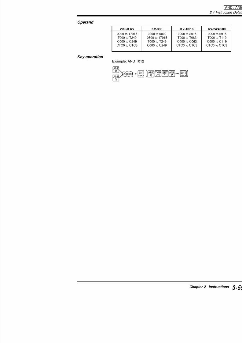
7/18/2019 Keyence Programming
http://slidepdf.com/reader/full/keyence-programming 83/392
Key operation Example: AND T012
( )SET1
TMR(T)
AND8 AND
8ANB5
ANL2Operand ENT
R-SRCHENTR-SRCH
CTC0 to CTC3 C000 to C249 CTC0 to CTC
2.4 Instruction Details
OR: Or
ORB: Or Bar
Connects N.O. contact iprevious contact.
Connects N.C. contact inprevious contact.
OR9
ORB6
nnnn
nnnn:
:
OR / ORB
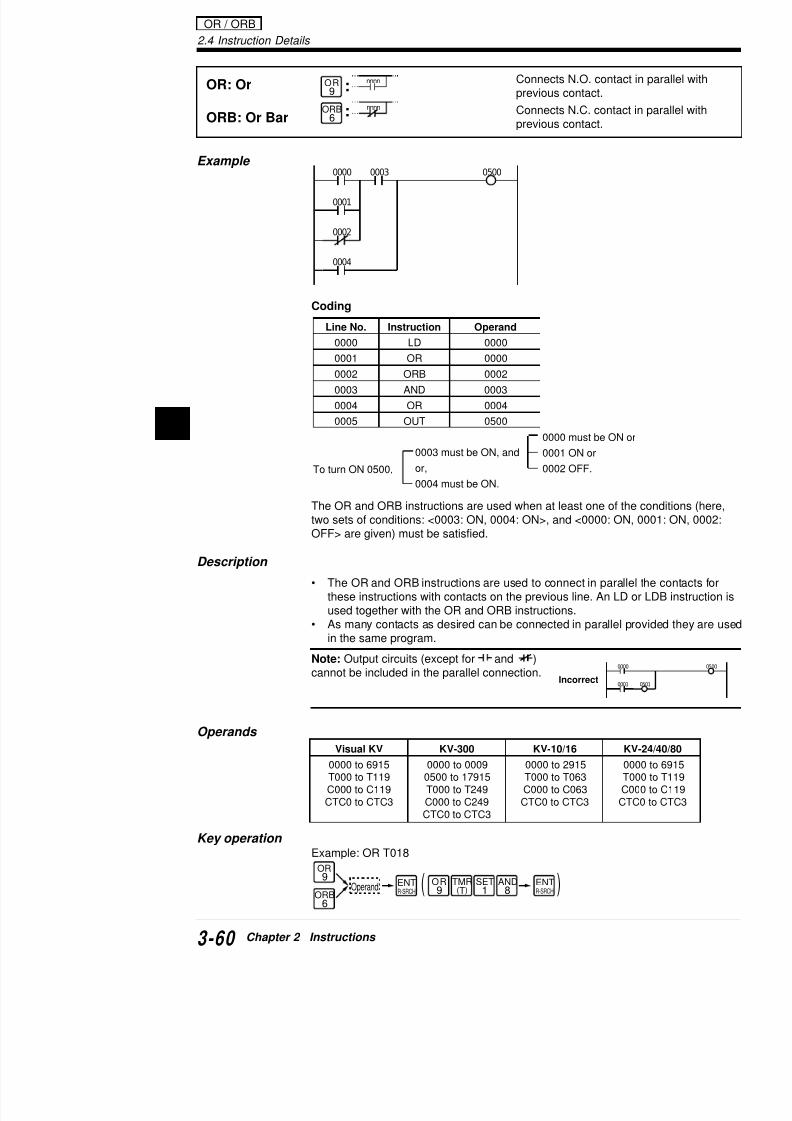
7/18/2019 Keyence Programming
http://slidepdf.com/reader/full/keyence-programming 84/392
2
Example
Coding
The OR and ORB instructions are used when at least one of the two sets of conditions: <0003: ON, 0004: ON>, and <0000: ON, 0OFF> are given) must be satisfied.
Description
• The OR and ORB instructions are used to connect in parallel these instructions with contacts on the previous line. An LD oused together with the OR and ORB instructions.
• As many contacts as desired can be connected in parallel proin the same program.
Note: Output circuits (except for and )cannot be included in the parallel connection.
0000 0003 0500
0004
0002
0001
Line No. Instruction Operand
0000 LD 0000
0001 OR 0000
0002 ORB 0002
0003 AND 0003
0004 OR 0004
0005 OUT 0500
0000
0001
To turn ON 0500,
0000 must be ON or
0001 ON or
0002 OFF.
0003 must be ON, and
or,
0004 must be ON.
Incorrect
ANL: And LoadConnects in smore contact
ANL2 :
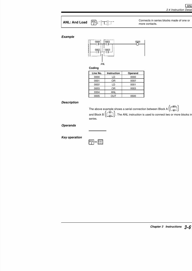
7/18/2019 Keyence Programming
http://slidepdf.com/reader/full/keyence-programming 85/392
Example
Coding
Description
The above example shows a serial connection betwee
and Block B
0001
0003 . The ANL instruction is used to
series.
Operands
Key operation
0000 0001 0500
00030002
ANL
Line No. Instruction Operand
0000 LD 0000
0001 OR 0002
0002 LD 0001
0003 OR 0003
0004 ANL0005 OUT 0500
ANL2
ENTR-SRCH
2.4 Instruction Details ANL
0000 0002 05000004
Applications of ANL Instruction

7/18/2019 Keyence Programming
http://slidepdf.com/reader/full/keyence-programming 86/392
2
0003 00050001
Line No. Instruction Operand
0000 LD 0000
0001 OR 0001
0002 LD 0002
0003 OR 0003
0004 ANL
0005 LD 0004
0006 OR 0005
0007 ANL
0008 OUT 0500
Line No. Instruction
0000 LD
0001 OR
0002 LD
0003 OR
0004 LD
0005 OR
0006 ANL
0007 ANL
0008 OUT
Coding (1) Coding (2)
• The ANL instruction can be used as many times as desired. Nin example (2) above, ANL is entered one less time than the nbe connected.
• Also, ANL can be used only 8 times or less in example (2), w(1) it can be used as many times as desired.
Note: "LOGIC ERROR" is displayed on the programmer when A
more times in example (2).
Example
ORL: Or LoadConnects in pmore contacts
ORL3 :

7/18/2019 Keyence Programming
http://slidepdf.com/reader/full/keyence-programming 87/392
Coding
Description
The above example shows a parallel connection of Bl
and Block B0002 0003
. The ORL instruction is used to
parallel.
Operands
Key operation
Line No. Instruction Operand
0000 LD 0000
0001 AND 0001
0002 LD 0002
0003 AMD 0003
0004 ORL
0005 OUT 0500
0000 0001 0050
00030002ORL
ORL3
ENTR-SRCH
2.4 Instruction Details
Applications of ORL Instruction
0000 0001 0500
00030002
Block
Block
ORL

7/18/2019 Keyence Programming
http://slidepdf.com/reader/full/keyence-programming 88/392
2
Coding (1) Coding (2)
• The ORL instruction can be used as many times as desired. Nin example (2) above, ORL is entered one less time than the nbe connected.
• Also, ORL can be used only 8 times or less in example (2), w(1) it can be used as many times as desired.
Note: "LOGIC ERROR" is displayed on the programmer when Oor more in example (2).
00030002
00050004
Line No. Instruction Operand
0000 LD 0000
0001 AND 0001
0002 LD 0002
0003 AND 0003
0004 ORL
0005 LD 0004
0006 AND 0005
0007 ORL
0008 OUT 0500
Line No. Instruction
0000 LD
0001 AND
0002 LD
0003 AND
0004 LD
0005 AND
0006 ORL
0007 ORL
0008 OUT
Block
Block
OUT: Out
OUB: Out Bar
Outputs ON/OF
Outputs inverterelay coil.
OUTA
OUBB
nnnn
nnnn
:
:

7/18/2019 Keyence Programming
http://slidepdf.com/reader/full/keyence-programming 89/392
Example
Coding
Description
• When input relay 0000 turn ON, output relay 0500 0501 turns OFF.
• The OUT and OUB instructions are used to drive rinternal utility relays, and latch relays. These instrurelays, timers, counters, or data memories.
Note: Double coilWhen one output relay receives input from two or mor
priority is given to the instruction that is entered last.
When 0001 is OFF, 0500 does not turn ON even if 00
Operands
Key operation
0000 0500
0501
Line No. Instruction Operand
0000 LD 0000
0001 OUT 0500
0002 OUB 0501
OUT OUB
Visual KV KV-300 KV-10/16
0000 to 1915 0500 to 1915 0500 to 1915
2009 2009 20092300 to 17915 2300 to 17915 2300 to 2915
2.4 Instruction Details
SET: Set
RES: Reset
Turns ON specified relay and enables this relay to r
Turns OFF specified relaywhen input is ON.
SET1
RES0
nnnnRES
nnnnSET:
:
SET / RES

7/18/2019 Keyence Programming
http://slidepdf.com/reader/full/keyence-programming 90/392
2
Example
Coding
Description
• Output relay 0500 remains ON after input relay 0000 turns OF0500 turns OFF when input relay 0001 turns ON.
• SET instruction sets a latch whereas RES instruction resets it• RES instruction not only turns OFF relay coils but serves as a
a timer or counter is used as an operand.
Note: The SET and RES instructions can be entered in any orde
that priority is given to the instruction that is entered last.In the above example, when both 0000 and 0001 are ON, RES hSET, causing 0500 to remain OFF.
Tips
Differences between SET/RES and KEEP
Basically , SET/RES and KEEP ( See above and p. 3-80 ) serve• SET and RES can be used separately. Therefore, RES can b
SET.
Another instruction may be placed between SET and RES.• KEEP needs only three lines of program, therefore saving me
used a number of times.
0000
0001
0500SET
0500RES
Line No. Instruction Operand
0000 LD 0000
0001 SET 0500
0002 LD 0001
0003 OUB 0500
0001 00020001
0002 C000RES
#00100
00000C000
#00100
0000C000
0000 0500 0000 KE
Example
TMR: 0.1-s TimerSets a 16-bit on-deladown in 0.1-s decrem
TMR(T)
#ddddd
Txxx
0000 #00010
:
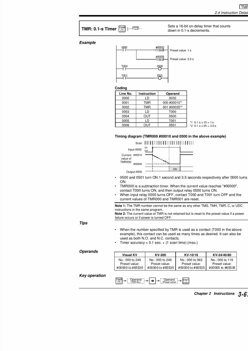
7/18/2019 Keyence Programming
http://slidepdf.com/reader/full/keyence-programming 91/392
Coding
Timing diagram (TMR000 #00010 and 0500 in the a
• 0500 and 0501 turn ON 1 second and 3.5 secondsON.
• TMR000 is a subtraction timer. When the current vcontact T000 turns ON, and then output relay 0500
• When input relay 0000 turns OFF, contact T000 ancurrent values of TMR000 and TMR001 are reset.
Note 1: The TMR number cannot be the same as any otherinstructions in the same program.Note 2: The current value of TMR is not retained but is rese
*1 0.1 s*2 0.1 s
0000
T000
T001
0500
0501
#00010
T000
#00035
T001
Preset value: 1 s
Preset value: 3.5 s
Line No. Instruction Operand
0000 LD 0000
0001 TMR 000 #00010*1
0002 TMR 001 #00035*2
0003 LD T000
0004 OUT 0500
0005 LD T0010006 OUT 0501
OFF
ON
ON
#00010
#00000
Output 0500
Scan
Input 0000
Current
value ofTMR000
2.4 Instruction Details
Example
TMH: 0.01-s TimerSets a 16-bit on-decounts down in 0.0
LDB4
OR9FUN
#ddddd Txxx TH
0000 #00010
:
TMH
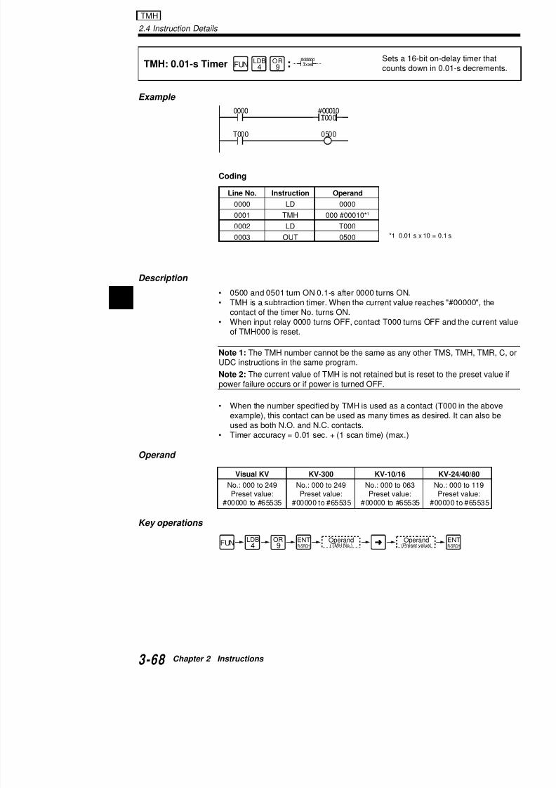
7/18/2019 Keyence Programming
http://slidepdf.com/reader/full/keyence-programming 92/392
2
Coding
Description
• 0500 and 0501 turn ON 0.1-s after 0000 turns ON.• TMH is a subtraction timer. When the current value reaches "
contact of the timer No. turns ON.• When input relay 0000 turns OFF, contact T000 turns OFF an
of TMH000 is reset.
Note 1: The TMH number cannot be the same as any other TMSUDC instructions in the same program.
Note 2: The current value of TMH is not retained but is reset to tpower failure occurs or if power is turned OFF.
• When the number specified by TMH is used as a contact (T00example), this contact can be used as many times as desiredused as both N.O. and N.C. contacts.
• Timer accuracy = 0.01 sec. + (1 scan time) (max.)
Operand
*1 0.01 s x 10 = 0.1
0000
T000 0500
#00010
T000 T
H
Line No. Instruction Operand
0000 LD 0000
0001 TMH 000 #00010*1
0002 LD T000
0003 OUT 0500
Visual KV KV-300 KV-10/16 KV
E l
TMS: 1-ms TimerSets a counts
SET1
ANB5FUN
#ddddd
Txxx T
S:
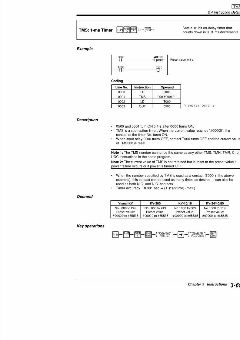
7/18/2019 Keyence Programming
http://slidepdf.com/reader/full/keyence-programming 93/392
Example
Coding
Description
• 0500 and 0501 turn ON 0.1-s after 0000 turns ON.• TMS is a subtraction timer. When the current value
contact of the timer No. turns ON.• When input relay 0000 turns OFF, contact T000 tu
of TMS000 is reset.
Note 1: The TMS number cannot be the same as anyUDC instructions in the same program.
Note 2: The current value of TMS is not retained but ipower failure occurs or if power is turned OFF.
• When the number specified by TMS is used as a cexample), this contact can be used as many times used as both N.O. and N.C. contacts.
• Timer accuracy = 0.001 sec. + (1 scan time) (max.
Operand
*1 0.00
0000
T000 0500
#00100
T000 T
SPreset value: 0.1 s
Line No. Instruction Operand
0000 LD 0000
0001 TMS 000 #00010*1
0002 LD T000
0003 OUT 0500
Visual KV KV-300 KV-10/16
No 000 to 249 No 000 to 249 No 000 to 06
2.4 Instruction Details
Applications of TMR instruction
One-shot circuit
When input relay 0000 turns ON, output relay 0500 turns ON andspecified time.
0000 #00020T000
2 sec.
TMR

7/18/2019 Keyence Programming
http://slidepdf.com/reader/full/keyence-programming 94/392
2
Timing diagram
Coding
Off-delay circuit
When input relay 0000 turns ON, output relay 0500 turns ON. 05specified time after 0000 turns OFF.
Timing diagram
T0000500 0500
T000
OFF
ON
ONON
0000
0500
Line No. Instruction Operand
0000 LD 0000
0001 OR 0500
0002 TMR 000 #00020
0003 ANB T000
0004 OUT 0500
0000 T000
00000500
0500
#00020 T000
OFF
ON
0000
2 sec.
2 sec. 2 sec.
On-delay circuit
Output relay 0500 turns ON in a specified time after inWhen input relay 0000 turns OFF, output relay 0500 a
0000 #00020
T0002 sec.

7/18/2019 Keyence Programming
http://slidepdf.com/reader/full/keyence-programming 95/392
Timing diagram
Coding
Flicker circuit
Output relay 0500 turns ON and OFF repeatedly while
Timing diagram
T000 0500
OFF
ON
ON
0000
0500
Line No. Instruction Operand
0000 LD 0000
0001 TMR 000 #00020
0002 LD T000
0003 OUT 0500
0000 T001
T000
0500
#00020 T000
#00010 T001
2 sec.
1 sec.
OFF
ON
0000
2 s 1 s
2.4 Instruction Details
Example
C: Counter Sets a 16-bit up-#ddddd
nnnnCxxx
CTR(C) :
Reset input Preset value
C

7/18/2019 Keyence Programming
http://slidepdf.com/reader/full/keyence-programming 96/392
2
Coding
Timing diagram (C000#00010 and 0500 in the above example
Description
• The counter performs one counting at the rising edge of clockcurrent value reaches the preset value, the coil of specified N
• When a reset input (b [N.C.] contact) turns ON, the current co
to "00000".• Since C is software counter which is set on the program, the
depends on the scan time.
N t 1 Wh t i t i id d i (N O ) t t
0001
C000 0500
0000
#00010C000
Line No. Instruction Operand
0000 LDB 0001
0001 C 000 #00010 0000
0002 LD C000
0003 OUT 0500
ON
#00010 1 2
3 4
5 6
7 8
9 10
C0000500
OFF
ON
Counter No.
Count input
0000(Count input)
0001(Reset input)
Current valueof C000
Details of counter
Extended ladder
• The counter for the KV Series supports the extend
0001 2007
0000
#00010C005
KV counter

7/18/2019 Keyence Programming
http://slidepdf.com/reader/full/keyence-programming 97/392
• The extended ladder allows you to connect contaccounter in series, reducing the number of ladder pr
In the following example, the counter starts counting wturns ON. When the current counter value reaches "30ON.
Coding
"CON instruction" (p. 3-102)
For details of the extended ladder, refer to "1.5 Extend(p.3-29).
Operands
Key operation
0002 C002 0500
0004
#00300C002
Line No. Instruction Operand
0000 LDB 0002
0001 C 002 #00300 00040002 CON
0003 AND C002
0004 OUT 0500
0000
CTR(C)
Operand(Counter No.)
Operand(Preset value)
Ope(Coun
Visual KV KV-300 KV-10/16
No.: 000 to 249 No.: 000 to 249 No.: 000 to 06Count input: Count input: Count input:
0000 to 17915 0000 to 0009, 0000 to 29150500 to 17915
Preset value: Preset value: Preset value#00001 to #65535 #00000 to #65535 #00000 to #655
2.4 Instruction Details
Applications of C (counter) instruction
Long-duration timer
Sets a long-duration timer by combining a timer and a counter.Output 0500 turns ON in 1 hour.
CodingSpecial utility relay(1-second clock)
C

7/18/2019 Keyence Programming
http://slidepdf.com/reader/full/keyence-programming 98/392
2
0001
20090000
#09999C002
2002 0500#01000C002
"1.3.7 Special Utility Rela
Accumulator timer (Remains ON in case of power failure)
Coding
Large capacity counter
Coding
Multi-level setting
Sets a multi-level counter using arithmetic instructions.
0000
2006
#03600C002
C002 0500
( )
Line No. Instruction
0000 LDB
0001 C
0002 LD
0003 OUT
0001 C001
2006
#03600C001
0001
1000
#00600C002
C001 1000
Line No. Instruction
0000 LDB
0001 ANB
0002 C
0003 LD
0004 OUT0005 LDB
0006 C
0002 C000
0000
#10000C000
0002
1000
#65535C001
C000 1000
Line No. Instruction
0000 LDB0001 ANB
0002 C
0003 LD
0004 OUT
0005 LDB
0006 C
Coding
Line No. Instruction Operand Line No.
0000 LDB 0002 0010
0001 C 002 #09999 0000 0011
0002 LD 2002 0012
0003 LDA C002 00130004 CON 0014

7/18/2019 Keyence Programming
http://slidepdf.com/reader/full/keyence-programming 99/392
Counter multi-level setting
Outputs in 3 different levels according to the counter c
Current counter value• 00000 to 00999 0500 turns ON.• 01000 to 01999 0501 turns ON.• 02000 to 02999 0502 turns ON.
Coding
0005 MPS 0015
0006 CMP #01000 0016
0007 CON 0017
0008 ANB 2009 0018
0009 OUT 0500 0019
0001
20110000
#09999C000
2002 0500#00999CMP
2011 0501#01999CMP
2011
0500
0500 0501 0502#02999
CMP
C000LDA
Line No. Instruction Operand
0000 LDB 0001
0001 C 000 #09999 0000
0002 LD 2002
0003 LDA C000
0004 CON
0005 MPS
0006 CMP #00999
0007 CON
0008 ANB 2011
0009 OUT 0500
2.4 Instruction Details
Example
UDC: Up-Down Counter Sets a 16-bit upUDC xxx
#dddddUPDWRES
ANB5
ANL2FUN
0001 UDC 000
UP
UP input
:
UDC

7/18/2019 Keyence Programming
http://slidepdf.com/reader/full/keyence-programming 100/392
2
Coding
Timing diagram
• When UP input relay (0001) turns ON, the current value of the
incremented by one. When DOWN input relay (0002) turns Ois decremented by one.
• C000 turns ON when the digit shifts (#00009 to #00000, or #0
0002
0003
C000 0500
UP #00009
DW
RES
Line No. Instruction Operand
0000 LD 0001
0001 LD 0002
0002 LD 0003
0003 UDC 000 #00009
0004 LD C000
0005 OUT 0500
1
2 34
56
78
9
OFF
ON
OFF
ON
OFF
ON
OFF
ON
DOWN input
RESET input
Current value of C000Carry Carry
ON
C000
Input for up 0001
Input for down 0002
Input for resetting0003
Application of UDC instruction
Multi-level UP/DOWN counter
UP/DOWN counter which allows a count setting value
Low-order 4
0001
0002
UDC 000
UP #09999
BCD
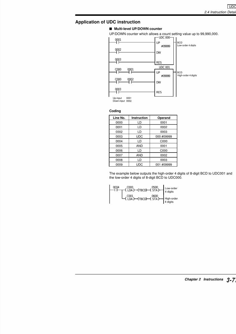
7/18/2019 Keyence Programming
http://slidepdf.com/reader/full/keyence-programming 101/392
Coding
The example below outputs the high-order 4 digits of 8the low-order 4 digits of 8-digit BCD to UDC000.
0003
DW
RES
C000
C000
0001
0002
0003
UDC 001
UP #09999
DW
RES
00010002
BCDHigh-order 4
Line No. Instruction Operand
0000 LD 0001
0001 LD 0002
0002 LD 0003
0003 UDC 000 #09999
0004 LD C000
0005 AND 0001
0006 LD C000
0007 AND 0002
0008 LD 0003
0009 UDC 001 #09999
0004 C000LDA TBCD 0500STA
C001LDA TBCD
0600STA
Up-inputDown-input
Low-order4 digits
High-order4 digits
2.4 Instruction Details
Example
DIFU: Differentiate Up
DIFD: Differentiate Down:
Detects rising edge of inpuON specified relay for 1st
Detects falling edge of inpON specified relay for 1st
nnnn
DIFD
nnnn
DIFU
SET1
RES0
RES0
FUN
FUNOR9
0000 1000
:
:
DIFU / DIFD
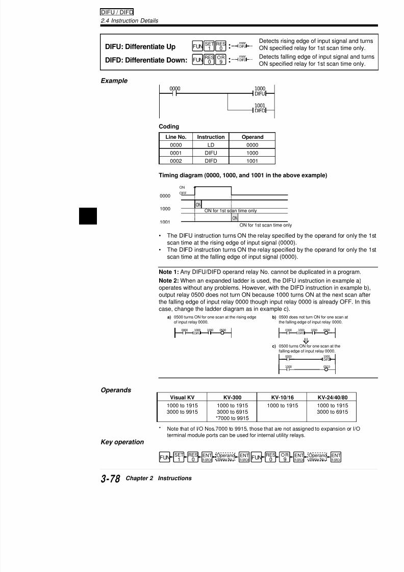
7/18/2019 Keyence Programming
http://slidepdf.com/reader/full/keyence-programming 102/392
2
Coding
Timing diagram (0000, 1000, and 1001 in the above example)
• The DIFU instruction turns ON the relay specified by the operscan time at the rising edge of input signal (0000).
• The DIFD instruction turns ON the relay specified by the operscan time at the falling edge of input signal (0000).
Note 1: Any DIFU/DIFD operand relay No. cannot be duplicated
Note 2: When an expanded ladder is used, the DIFU instruction operates without any problems. However, with the DIFD instructioutput relay 0500 does not turn ON because 1000 turns ON at ththe falling edge of input relay 0000 though input relay 0000 is alrecase, change the ladder diagram as in example c).
0000
1000DIFU
1001DIFD
Line No. Instruction Operand0000 LD 0000
0001 DIFU 1000
0002 DIFD 1001
ON
ON
0000
1000
1001
OFF
ON
0000 1000
1000DIFU
0500 0000 1000
1000DIFD
05
a) 0500 turns ON for one scan at the rising edge
of input relay 0000.
c) 0500 turns ON for one sca
b) 0500 does not turn ON for
the falling edge of input re
ON for 1st scan time only
ON for 1st scan time only
Application of DIFU, DIFD instructions
One-shot circuit using the differentiate instruct
When input relay 0000 turns ON/OFF, output relay 05shot (1 second).
Coding
0000 1000 Li N

7/18/2019 Keyence Programming
http://slidepdf.com/reader/full/keyence-programming 103/392
Timing diagram
Alternating circuit
Every time input relay 0000 turns ON, output relay 050nately.
Coding
0000
1000 T001
0500
1001 T002
0501
0500
1000DIFU
1001DIFD
#00010
T001
0501
#00010 T002
Line No.
0000
0001
0002
0003
0004
0005
0006
0007
0008
0009
0010
0011
0012
ON
ON
0000
1000
1001
0500
0501
OFF
ON
OFF
ON
OFF
ON
0000 1000DIFU
Line No.
0000
1 s
1 s
2.4 Instruction Details
Example
KEEP: Keep
Turns ON specified relay wrelay turns ON and enableremain ON. And, turns OFwhen RESET input relay tu
OR9
ORL3FUN
KEEP
SETRES
nnnn
KEEPSET i
:
KEEP

7/18/2019 Keyence Programming
http://slidepdf.com/reader/full/keyence-programming 104/392
2
Coding
Description
• When SET input relay No. 0001 is ON and RESET input relay0500 turns ON.
• When RES input (0002) is ON, output relay 0500 turns OFF.• When both 0001 and 0002 are OFF, the previous status is ret
Note 1: When 0500 used for KEEP instruction in the above exaOUT instruction ( ), it forms a double coil. In such a case, prinstruction that is entered last "Double coil" (p. 3-65)
Note 2: When both 0001 and 0002 are ON, RESET (0002) has(0001), causing 0500 to turn OFF.
Tips Internal utility relay latching function
The ON/OFF status of an internal utility relay immediately beforestored by setting the memory switch (MEMSW).
"MEMSW instruction" (p. 3-92)
If this stored utility relay is used for a latching instruction (SET orsettings can be stored while the power is off.
Coding
Line No. Instruction Operand
0000 LD 0000
0001 DIFU 1000
0002 DIFD 1001
0001
0002
KEEP
SET 0500
RESRES RESET input
SET input
0001 KEEP
MEMSW
$0004
Stores the status ofinternal utility relays1000 through 1915.
Line No. Instruct
0000 MEMS
0001 LD
0500
Application of KEEP instruction
Detection of chewing gum packs
Detects chewing gum packs over the carton using the(0001 to 0003). If the switch detects that one or more missing, output relay 0500 turns ON for 1 s.
The timing clock is generated from the visible beam p
E SET h ll i l
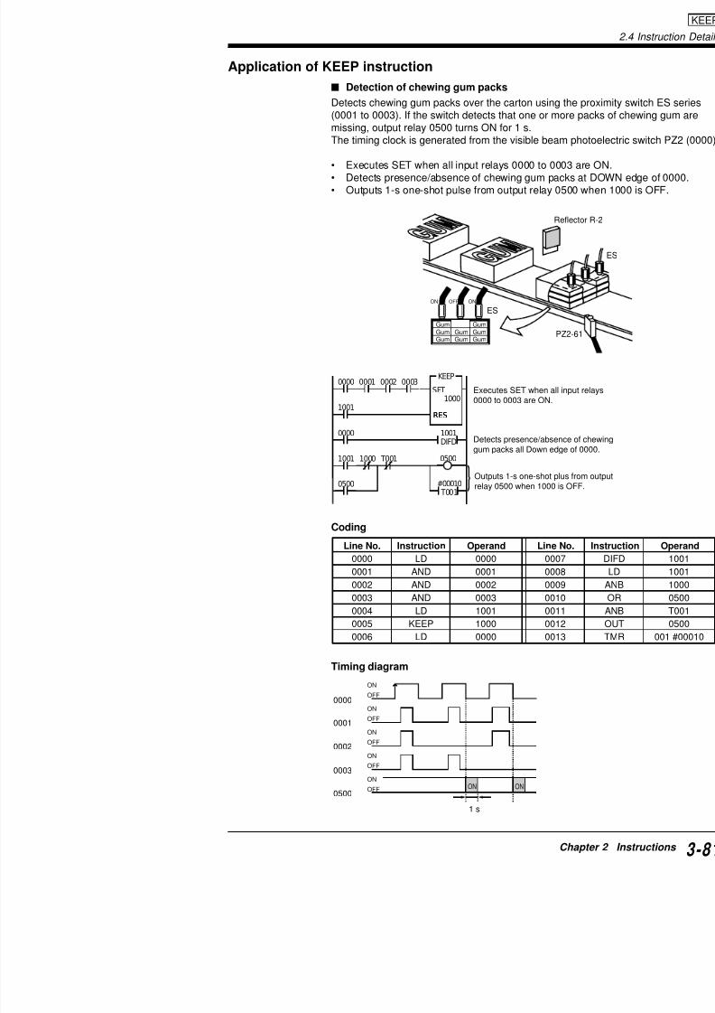
7/18/2019 Keyence Programming
http://slidepdf.com/reader/full/keyence-programming 105/392
• Executes SET when all input relays 0000 to 0003 a• Detects presence/absence of chewing gum packs • Outputs 1-s one-shot pulse from output relay 0500
Coding
Reflec
PZ2-6
ESON
GumGumGum
GumGum
GumGumGum
OFF ON
0000
1001
0000 1001DIFD
#00010 T001
1001 1000 T001
0500
0001 0002 0003 KEEP
SET 1000
RESRES
0500
Line No. Instruction Operand Line No.
0000 LD 0000 0007
0001 AND 0001 00080002 AND 0002 0009
0003 AND 0003 0010
0004 LD 1001 0011
Executes SET when all inpu0000 to 0003 are ON.
Detects presence/absence ogum packs all Down edge of
Outputs 1-s one-shot plus frrelay 0500 when 1000 is OF
2.4 Instruction Details
SFT: Shift Sets a shift register.
Example
SFTnnnn
mmmm
DCLK RES
OR9
ORL3FUN
0001SFT
D
Data input
:
SFT
Relay shift

7/18/2019 Keyence Programming
http://slidepdf.com/reader/full/keyence-programming 106/392
2
Coding
Timing diagram
0002
0003
1002 0500
D
1000
CLK
1002
RES
Line No. Instruction Operand
0000 LD 0001
0001 LD 0002
0002 LD 00030003 SFT 1000 1002
0004 LD 1002
0005 OUT 0500
0500
1002
1001
1000
0002 OFF
ON
0001
0003
OFF
ON
OFF
ON
ON
ON ON
ON ON
10
0
ON ON
ON ON
10
0
10
10
10
10
10
0
A B C D E F G
RESET input
First relay No.
Clock
Last relay No.
RESET input
Data input
Clock
yoperation
Lost
Lost
Lost
Lost
Lost
Lost
Lost
Operands
* Note that of I/O Nos. 7000 to 9915, those that are not asunit ports can be used for internal utility relays.
Key operation
Visual KV KV-300 KV-10/16
1000 to 1915 1000 to 1915 1000 to 19153000 to 6915 3000 to 6915
*7000 to 9915

7/18/2019 Keyence Programming
http://slidepdf.com/reader/full/keyence-programming 107/392
Applications of SFT instruction
Alternating circuit
Every time input relay No. 0000 turns ON, 0500 turns
Coding
Timing diagram
Reference: Alternating circuit can be configured withoThe following circuit does the same operation as the c "DIFU instruction" (p. 3-78)
Coding
1000
0000
2003
1000 0500
SFT
D
1000
CLK
1000
RES
Line No.
0000
0001
0002
00030004
0005
ON
OFF
ON ON ON ON ON
0000
0500
Line No.
0000
0001
0002
FUN OR
9ORL
3Operand(Relay No.)
Oper(Relay
ENTR-SRCH
0000
1000DIFU
1000 0500 0500
2.4 Instruction Details
Resetting internal utility relays
When input relay No. 0000 turns ON, all internal utility relays No.turn OFF.
SFT instruction can be substituted for RES instruction. This applito reset many relays at one time.(All relays 3000 through 9915 can also be turned OFF at one tim
C di g
SFT

7/18/2019 Keyence Programming
http://slidepdf.com/reader/full/keyence-programming 108/392
2 Line No. Instructio
0000 LD
0001 SET
0002 LDB
0003 T001
0004 LD
0005 LD
0006 LD
0007 SFT
0008 LD
0009 OUT
0010 LD
0011 OUT
0012 LD0013 OUT
0014 LD
0015 OUT
Coding
Repeat shift circuit
Turns ON every output for a second sequentially. Sets 1000 to 2scan only at startup) and shifts outputs from 0500 to 0504 every When 1005 turns ON, 1000 is set and the same sequence as ab
Coding
2003
2003
0000
SFT
D
1000
CLK
1915
RES
Line No. Instructio
0000 LD
0001 LD
0002 LD
0003 SFT
2003
T001
2008
T001
2003
SFT
D
1000CLK
1005
RES
1000
1001
1002
1003
#00010 T001
1000SET
0500
0501
0502
0503
Asynchronous shift register
Turns ON input relay 0002 to reset the shift register (1input to 0000 does not synchronize with the clock inpu
Coding
1100
0000 1100DIFU
1000SET
Line No.0000
0001
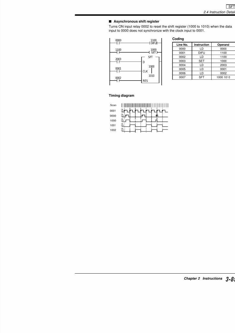
7/18/2019 Keyence Programming
http://slidepdf.com/reader/full/keyence-programming 109/392
Timing diagram
2003
0001
0002
SFT
D
1000
CLK
1010
RES
0002
0003
0004
0005
0006
0007
ONOFF
ON
OFFONOFF
ONOFF
ONOFF
1001
0000
0001
1002
1000
Scan
2.4 Instruction Details
HSP: High SpeedShortens time constant ofrelay to 10 µs to increase
SET1
AND8FUN
HSPnnnn
0000 HSP
0001
Example
Enable input
:
HSP

7/18/2019 Keyence Programming
http://slidepdf.com/reader/full/keyence-programming 110/392
2
0001 0500SET
0002 0501SET
0003 0500
RES
0501RES
Coding
Timing diagram
Line No. Instruction Operand
0000 LD 0000
0001 HSP 0001
0002 LD 0001
0003 SET 0500
0004 LD 0002
0005 SET 0501
0006 LD 0003
0007 RES 0500
0008 RES 0501
ON ON ON
ON
0000
0002
0001
0003
0500
ON ON
ONON
ON ON
OFF
ON
5 ms 5 ms 15 ms
Note 3: The HSP instruction must be specified when tspeed counter is used.
Note 4: When special utility relay 2813 and HSP instrtime, priority is given to the HSP instruction and the timµs.
Note 5: Connect a non-contact input for the HSP instrbounce from being entered.
D il f HSP I i

7/18/2019 Keyence Programming
http://slidepdf.com/reader/full/keyence-programming 111/392
Details of HSP Instruction
This section describes the operation of the HSP instru
Input signal width
Even if the input signal width is shorter than the scan when it turns ON during input process as in 1). Howevit turns ON any other time than the input process as inFor reliable signal reception, the input signal width mutime as in 3).
Scan time < Input signal width < Normal time cons
Switching the input time constant of expansion
Expansion input unit Expansion IKV-E4X KV-E4XTKV-E8X KV-E4XRKV-E16X
The input time constant of an expansion unit is initiallyIt can be changed to 10 µs by creating a ladder prograWindow, the LADDER BUILDER for KV programmingKV-P3E(01) handheld programmer.
Change the values of special utility relays 2609 to 261
OFF
ON
1) 2) 3)
Scan time
Outputdevice
Programexecution
Programexecution
Scan time
Inputdevice
Outputdevice
Outputdevice
Inputdevice
Special utility relay Description
2609 Input time constant of 1st unit. OFF
I i f d i OF
2.4 Instruction Details
Applications of HSP Instruction
High-speed fetching of input data
When the input signal at 0000 has pulses of 5-ms interval and 2-input relay 0001 is ON, fetches data from input relay 0000 at high1-s one-shot pulse from output relay 0500.
Coding
0001 HSP Line No. Instructi
HSP
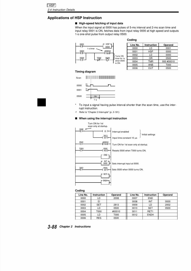
7/18/2019 Keyence Programming
http://slidepdf.com/reader/full/keyence-programming 112/392
2
Timing diagram
* To input a signal having pulse interval shorter than the scan trupt instruction.
Refer to "Chapter 3 Interrupts" (p. 3-191).
When using the interrupt instruction
0000
0000
0500 T000 0500
#00010 T000
0000 LD
0001 HSP
0002 LD
0003 OR
0004 TMR
0005 ANB
0006 OUT
ONOFF
ONOFF
0500
0000
0001
ON
2813SET
EI
#00010 T000
2008
0500
T000
END
INT
0500RES
0000
Turn ON for 1st scan only at startup.
Input time constant 10 µs
Turns ONtimer for 1swhen 0500is ON.
Resets 0500 when T000 turns ON.
Interrupt enabled
Initial setting
Sets interrupt input at 0000.
1-s timer
Scan
1 s
Turn ON for 1stscan only at startup.
MC: Master Control
MCR: Master ControlReset
Selects ON/OFFor counters set
Used in pairs wexecution of MC
LDB4
ANB5
ANL2
ANL2
MCR
MC FUN
FUN
0000 MC
Example
:
:

7/18/2019 Keyence Programming
http://slidepdf.com/reader/full/keyence-programming 113/392
MCR
0001 0500
0501
Coding
Description
• When 0000 is OFF, both 0500 and 0501 do not turON.
• When 0000 is ON, 0500 turns ON and 0501 turns ON.
• Regard the function of MC-MCR instructions as "p• When the input relay for MC is OFF, the instruction
MCR instructions function as follows:
Note: MC-MCR instructions cannot be used in the foll
1. Nesting 2.Improper c
Line No. Instruction Operand
0000 LD 0000
0001 MC
0002 LD 0001
0003 OUT 05000004 OUB 0501
0005 MCR
Instructions Function
OUT and OUB Correspond
TMR, TMH, and TMS Timer is res
C, SFT, KEEP, SET, RES, and CTH Previous sta
Other instructions such as TMIN Instruction i
2.4 Instruction Details
Details of MC-MCR Instructions
Position of MC-MCR instructions
MC-MCR instructions can be used in the following positions.
1. MC-MCR instructions canbe placed before or afterSTP-STE instructions.
STP
x x x x
MC
STP
x x x x
STE
2. MC-MCR instructions canbe placed between STPand STE instructions.
3. STP-Sbe plaand M
MC / MCR

7/18/2019 Keyence Programming
http://slidepdf.com/reader/full/keyence-programming 114/392
2
Making an input condition
The input condition for an MC instruction can be made as shown
Note: The scan time is not shortened even if the input relay of thOFF.
Output relays 0500 within and outside of the MC-MCR instructioncoil as shown below. "Double coil" (p. 3-65)
In this case, priority is given to the instruction that is entered last.
This relay is ignored.
MC
MCR
STE
STE
MC
MCR
0000 0001 0002 MC
MCR
0003 0500
MC
0003
0001
0500
MCR
0002 0500The last relay has priority.
Application of MC-MCR Instruction
Emergency stop circuit
When input relay 0000 is ON, 0500 turns ON for 1 s, tand then 0502 turns ON for 3 s, repeatedly.Once input relay 0000 turns OFF, 0500 turns ON whe
when 0002 is ON, and 0502 turns ON when 0003 is O
Timing diagram
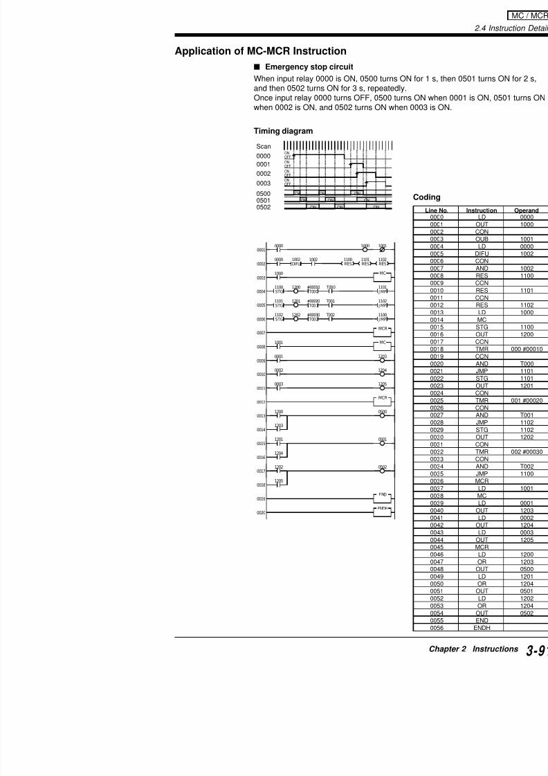
7/18/2019 Keyence Programming
http://slidepdf.com/reader/full/keyence-programming 115/392
CodingON ON
ON
ON
ON
ONON
ON ON
0003
0501
0001
0502
0000
Scan
0500
0002
ONOFF
ONOFF
ONOFF
ONOFF
1102RES
1101RES
1100RES
00000001
0002
0003
0004
0005
0006
0007
0008
0009
0010
0011
0012
0013
0014
0015
0016
0017
MC
MCR
MCR
10011000
0001 1203
1200
1203
0500
1201
1204
0501
1202 0502
0002 1204
0003 1205
1200
0000
T000
1000
MC1001
1002DIFU1002
T000#00010
STG1100
J MP1101
1201 T001 T001#00020
STG1101
J MP1102
1202 T002 T002#00030
STG1102
J MP1100
Line N00000001000200030004000500060007
00080009001000110012001300140015001600170018
00190020002100220023002400250026002700280029
003000310032003300340035
2.4 Instruction Details
FUN ANL2 ORB6 OperandENTR-SRCH
ENTR-SRCH
Key operation
Operands
MEMSW:Memory Switch
Sets memory switches.FUNMEMSW$nnnn
ANL2
ORB6 :
MEMSW

7/18/2019 Keyence Programming
http://slidepdf.com/reader/full/keyence-programming 116/392
2
$0000 to $FFFF
Example
Coding
• Specify 3 of SW3 and 0 and 1 of SW4 to reset the values of DM1900
up-down counter, CTH, and CTC when the operation is started.
Description Switch Nos. and functions are as follows. The switch consists of tion of the switch is specified by turning a certain bit ON or OFF.
0 0 1 1
3 2 1 0
1 0 0 0
3 2 1 0
0 0 0 0
3 2 1 0
0 0 0 0
3 2 1 0
SW4 SW3 SW2 SW1 MEMSW$3800
SW1SW2SW3SW4
Loads me
from EEP
Uses latc
function.
Uses latc
function.Uses latc
function.
Uses latc
MEMSW
$3800
Line No. Instruction Operand
0000 MEMSW $3800
Switch
No. Function of switch ONRetains e0 Cancels error when power is ON.
1 Action when "Memory error" occurs at
startup (due to data memory, counter
value, or retained content being erased).
2 Uses latch function of internal utility relays
1000 through 1915.
3 Uses latch function of internal utility relays
3000 through 3915.0 Uses latch function of internal utility relays
4000 through 4915.
1 Uses latch function of internal utility relays
Note 1: When a read-protected program is transferrbe read or modified from this PLC. Before read-proteccreate a backup copy of the program.
Note 2: When a 24-bit high-speed counter comparawhich specifies the numerical values of a 24-bit CTC ihigh-speed counter.
Note 3: The value of MEMSW can be changed eventhe new operation is not actually performed. The chanKV is turned off or stopped once and then restarted.

7/18/2019 Keyence Programming
http://slidepdf.com/reader/full/keyence-programming 117/392
(8)
23
0
0
0
0
0
0
0
0
1
11
1
1
1
1
1
(4)
22
0
0
0
0
1
1
1
1
0
00
0
1
1
1
1
(2)
21
0
0
1
1
0
0
1
1
0
01
1
0
0
1
1
(1)
20
0
1
0
1
0
1
0
1
0
10
1
0
1
0
1
0
1
2
3
4
5
6
7
8
9A
B
C
D
E
F
0 0 0 0
3 2 1 0
0
0 0 1 0
3 2 1 0
2
0 1 1
3 2 1
6
SW4 SW3 SW2
Retains all errors when power is ON.Retains utility relays 3000 through 399
(Example)
Clears DM0000 to DM0999when power is ON.
Retains Internal utility relay5000 through 5999 and 6000through 6999.
Details of MEMSW
Setting memory switches
Specify a hexadecimal number for each switch No.
Tips • The data entered for the memory switch is set into
gram is transferred to the KV PLC.• When MEMSW instruction is not entered into the p
Hexadeci-mal number
2.4 Instruction Details
NOP: No Operation Performs no opeRES0
ORL3FUN :
NOP END / ENDH
When ALL CLEAR [FNC60] or HANDHELD PROGRAMMER CL[FNC61] is executed to delete the program, NOP appears on all
program.NOP is not written by the KV IncrediWare (DOS)/LADDER BUILDgramming support software.
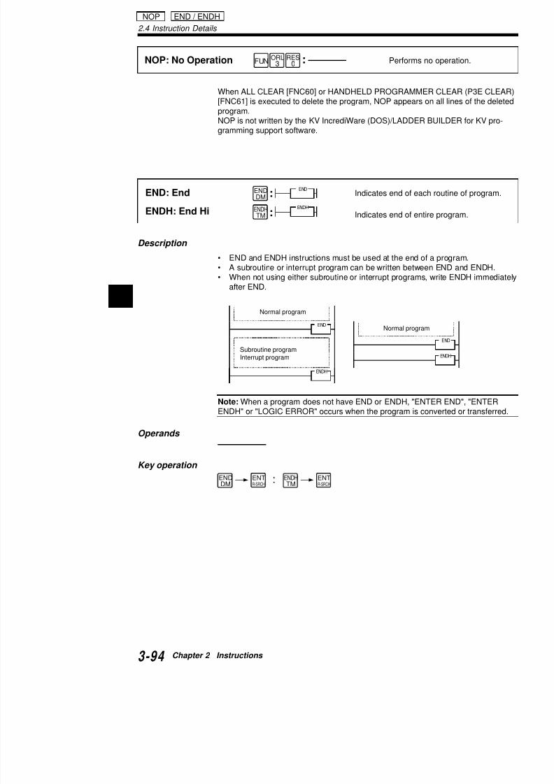
7/18/2019 Keyence Programming
http://slidepdf.com/reader/full/keyence-programming 118/392
2
END: End
ENDH: End Hi
Indicates end of each rout
Indicates end of entire pro
Normal program
ENDDM
ENDHTM
END
ENDH
EN
END
ENDH
END
Subroutine programInterrupt program
Normal program
END ENDHENT ENT
:
:
Description
• END and ENDH instructions must be used at the end of a pro• A subroutine or interrupt program can be written between EN
• When not using either subroutine or interrupt programs, write after END.
Note: When a program does not have END or ENDH, "ENTER EENDH" or "LOGIC ERROR" occurs when the program is convert
Operands
Key operation
Instruction Mnemo
W-ON: Wait ON W-O
2.4.2 Application Instructions
Application instructions are used for batch processingtransmitted to specified memory locations or changedover, parts of a program can be repeated or skipped w
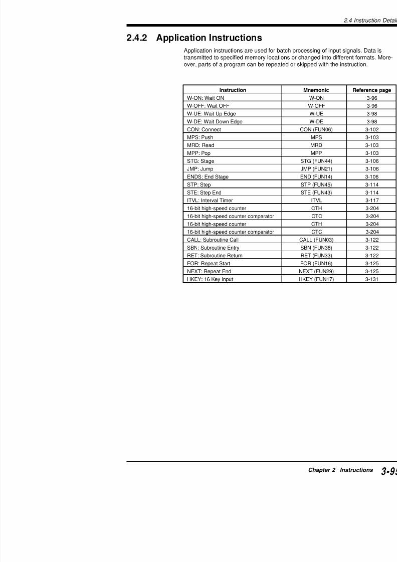
7/18/2019 Keyence Programming
http://slidepdf.com/reader/full/keyence-programming 119/392
W-OFF: Wait OFF W-OF
W-UE: Wait Up Edge W-U
W-DE: Wait Down Edge W-D
CON: Connect CON (FU
MPS: Push MPSMRD: Read MRD
MPP: Pop MPP
STG: Stage STG (FU
JMP: Jump JMP (FU
ENDS: End Stage END (FU
STP: Step STP (FU
STE: Step End STE (FU
ITVL: Interval Timer ITVL
16-bit high-speed counter CTH
16-bit high-speed counter comparator CTC
16-bit high-speed counter CTH
16-bit high-speed counter comparator CTC
CALL: Subroutine Call CALL (FU
SBN: Subroutine Entry SBN (FU
RET: Subroutine Return RET (FU
FOR: Repeat Start FOR (FU
NEXT: Repeat End NEXT (FU
HKEY: 16 Key input HKEY (FU
2.4 Instruction Details
Example
W-ON: Wait ON
W-OFF: Wait OFF
Turn ON second operandoperand relay contact turn
Turns ON second operandoperand relay contact turn
nnnnOFF
mmmm
nnnnON
mmmm
W-ONF
W-OFFL i
0000 0001ON
1000 W ON
:
:
W-ON / W-OFF

7/18/2019 Keyence Programming
http://slidepdf.com/reader/full/keyence-programming 120/392
2
Coding
Timing chart
• W-ON
When input relay 0000 is ON, output relay 0500 turns ON as soo0001 turns ON. 0500 remains ON until 0000 turns OFF.
• W-OFF
Line No. Instruction Operand
0000 LD 0000
0001 W-ON 0001 1000
0002 LD 1000
0003 OUT 0500
0004 LD 0002
0005 W-OFF 0003 1001
0006 LD 1001
0007 OUT 0501
1000 0500
1000
0002
1001 0501
0003OFF1001
W-ON
W-OFF
ON
0000
0001
10000500
OFF
ON
OFF
ON
ON
ON
Description
W-ON
• When input relay 0000 is ON output operand 1000
0000 0001
1000
00000001ON
1000
1000
Sameoperation
Input operand
Output operand

7/18/2019 Keyence Programming
http://slidepdf.com/reader/full/keyence-programming 121/392
• When input relay 0000 is ON, output operand 1000contact of input operand 0001 turns ON.
W-OFF
• When input relay 0002 is ON, output operand 1001contact of input operand 0003 turns OFF.
Note: Output operand relay Nos. for W-ON/W-OFF incated in a program.
Operands
* Note that of I/O Nos. 7000 to 9915, those that are
remote I/O unit ports can be used for internal utility
Key operation
0002 0003
1001
00020003OFF
1001
1001
W ON
Sameoperation
Input operand
Output operand
Visual KV KV-300 KV-10/16
nnnn: nnnn: nnnn:0000 to 17915 0000 to 0009 0000 to 2915
T000 to T249 0500 to 17915 T000 to T063C000 to C249 T000 to T249 C000 to C063CTC0 to CTC3 C000 to C249 CTC0 to CTC
mmmm: CTC0 to CTC3 mmmm:1000 to 1915 mmmm: 1000 to 19153000 to 9915 1000 to 1915
3000 to 6915*7000 to 9915
2.4 Instruction Details
Example
W-UE: Wait Up Edge
W-DE: Wait Down Edge
Turns ON second operanedge of first operand rela
Turns ON second operanedge of first operand rela
nnnn
mmmm
nnnn
mmmm
W-UEE
W-DEL o
0000
0001
1000W UE
:
:
W-UE / W-DE

7/18/2019 Keyence Programming
http://slidepdf.com/reader/full/keyence-programming 122/392
2
Coding
Timing chart
W-UE
• When input relay 0000 is ON, output relay 0500 turns ON at roperand relay 0001.
• As soon as input relay 0000 turns OFF, output relay 0500 turn
Line No. Instruction Operand
0000 LD 0000
0001 W-UE 0001 1000
0002 LD 1000
0003 OUT 0500
0004 LD 0002
0005 W-DE 0003 1001
0006 LD 1001
0007 OUT 0501
1000 0500
0002
1001 0501
0003
1001
W-UE
W-DE
ON
0000
0001
10000500
OFF
ON
OFF
ON
Description
W-UE
• When input relay 0000 is ON, the output operand tthe input operand.
0000 1002
0001
1000
00000001
1000
1000
1002DIFUSame
operation
Input operand
Output operand
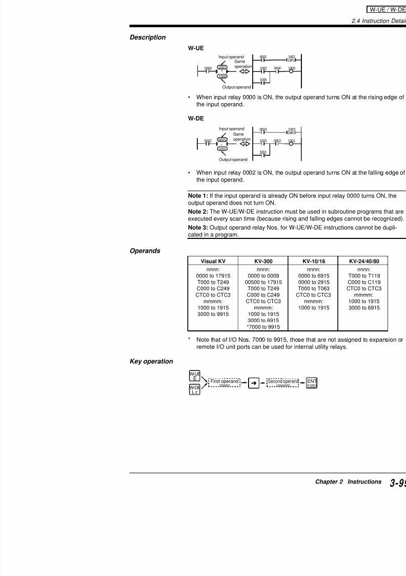
7/18/2019 Keyence Programming
http://slidepdf.com/reader/full/keyence-programming 123/392
W-DE
• When input relay 0002 is ON, the output operand tthe input operand.
Note 1: If the input operand is already ON before inpu
output operand does not turn ON.Note 2: The W-UE/W-DE instruction must be used in executed every scan time (because rising and falling e
Note 3: Output operand relay Nos. for W-UE/W-DE incated in a program.
Operands
* Note that of I/O Nos. 7000 to 9915, those that are remote I/O unit ports can be used for internal utility
0002 1003
1001
00020003
1001
1001
0003 1003DIFDSame
operation
Input operand
Output operand
Visual KV KV-300 KV-10/16
nnnn: nnnn: nnnn:0000 to 17915 0000 to 0009 0000 to 6915T000 to T249 00500 to 17915 0000 to 2915C000 to C249 T000 to T249 T000 to T063CTC0 to CTC3 C000 to C249 CTC0 to CTC
mmmm: CTC0 to CTC3 mmmm:1000 to 1915 mmmm: 1000 to 19153000 to 9915 1000 to 1915
3000 to 6915
*7000 to 9915
2.4 Instruction Details
Details of W-ON and W-UE Instructions
A combination of W-ON, W-OFF, W-UE, and W-DE instructions effective when used in programs controlling sequential operationtion of one operational step starts the next step.This section describes minute differences in the operation of thes
Difference between W-ON and W-UE
Output relay 0100 turns ON when b0000 and 0001 turn ON in any orde
0000
0001ON
1000
W-UE / W-DE

7/18/2019 Keyence Programming
http://slidepdf.com/reader/full/keyence-programming 124/392
2W-ON: Output relay 0500 turns ON when both input relays 000
ON in any order.
W-UE: Output relay 0501 turns ON only when input relay 0000input relay 0001.
Note: An input operand relay No. for these instructions can be duprogram, but output operand relay Nos. cannot be duplicated.
As shown above, W-UE requires a certain order for turning ON re0001, but W-ON does not. Therefore, W-UE is suitable for circuitevery input; W-ON is suitable for circuits that go on to the next opcertain condition is satisfied.
The operation of W-OFF and W-DE instructions are same as abowhich turns relays OFF.
0000 and 0001 turn ON in any orde
Output relay 1001 turns ON only w0000 turns ON before input relay 0
0100 0500
1000
0001
1001
1001 0501
ON
0000
0001
(W-ON)
(W-UE)
10000500
10010501
OFF
ON
OFF
ON
ON
ON
Application of W-UE Instruction
Input sequence check
Output relay 0500 turns ON when input relay 0000 is O0003 turn ON in this sequence.
Output relay 0500 turns OFF when input relay 0000 is
Coding0000 0001
1000Line No.
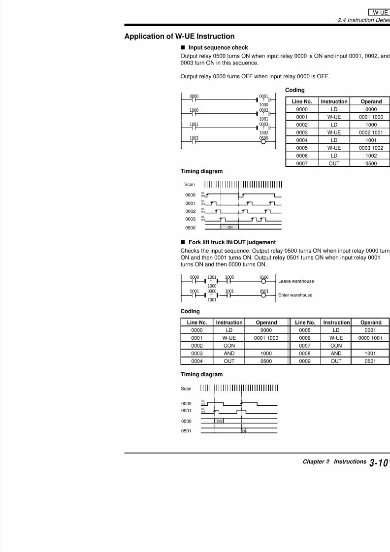
7/18/2019 Keyence Programming
http://slidepdf.com/reader/full/keyence-programming 125/392
Timing diagram
Fork lift truck IN/OUT judgement
Checks the input sequence. Output relay 0500 turns O
ON and then 0001 turns ON. Output relay 0501 turns turns ON and then 0000 turns ON.
Coding
0500
1000
1000 0002
1001
1001 0003
1002
1002
0000
0001
0002
0003
0004
0005
0006
0007
ON
ON
OFF
ONOFF
ONOFF
ONOFF0003
00010000
0500
0002
0000 0500
0501
1001
1000
0001
1000
10010000
1001
Line No. Instruction Operand Line No.
0000 LD 0000 0005
0001 W UE 0001 1000 0006
Scan
Leave warehouse
Enter warehouse
2.4 Instruction Details
Example
Coding
CON: ConnectRepresents series connecinstruction with another in
RES0
ORB6FUN
0000 0503050205010500
CON CON CON
:
CON
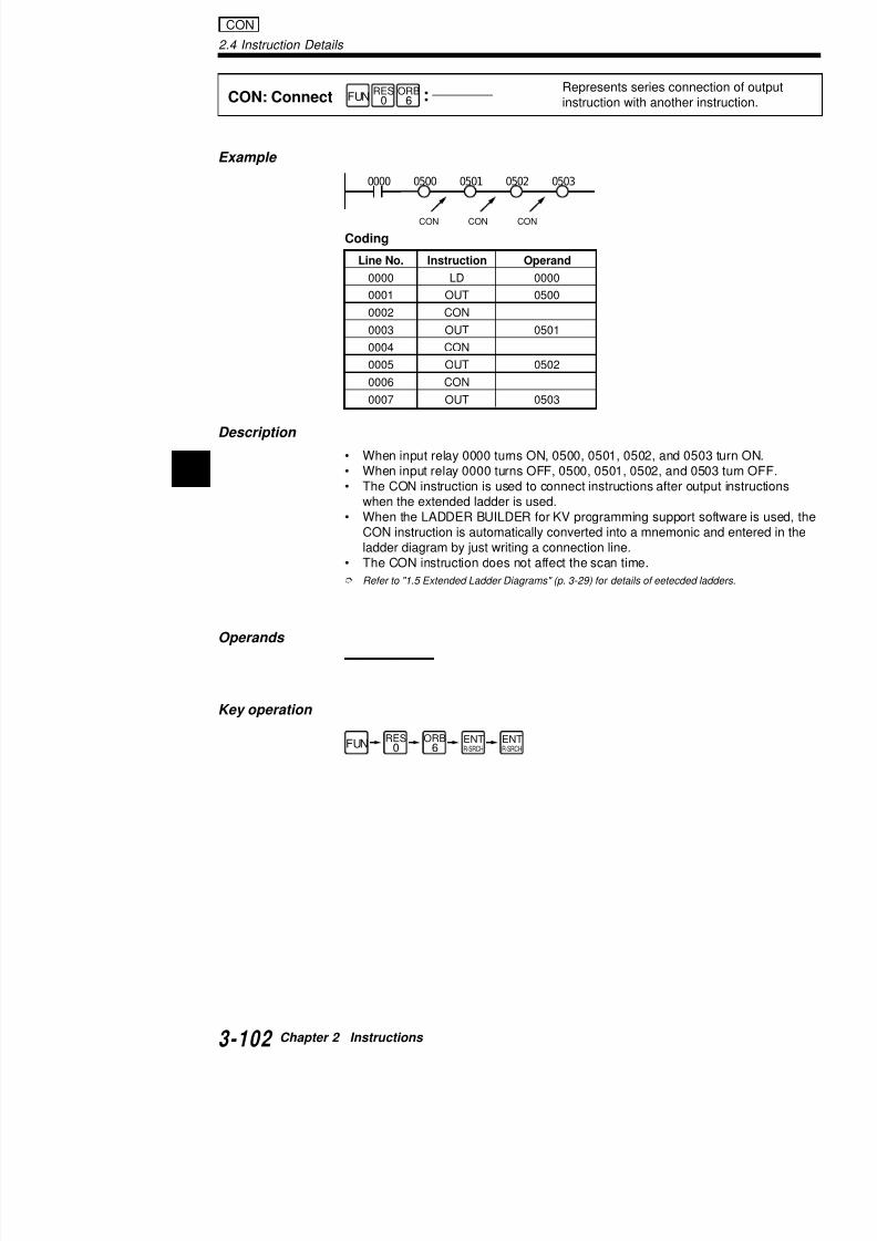
7/18/2019 Keyence Programming
http://slidepdf.com/reader/full/keyence-programming 126/392
2
Coding
Description
• When input relay 0000 turns ON, 0500, 0501, 0502, and 0503• When input relay 0000 turns OFF, 0500, 0501, 0502, and 050• The CON instruction is used to connect instructions after outp
when the extended ladder is used.• When the LADDER BUILDER for KV programming support so
CON instruction is automatically converted into a mnemonic aladder diagram by just writing a connection line.
• The CON instruction does not affect the scan time.
Refer to "1.5 Extended Ladder Diagrams" (p. 3-29) for details of eetecded lad
Operands
Key operation
Line No. Instruction Operand
0000 LD 0000
0001 OUT 0500
0002 CON
0003 OUT 0501
0004 CON
0005 OUT 0502
0006 CON
0007 OUT 0503
RES0
ORB6FUN ENT
R-SRCHENTR-SRCH
Example
MPS: Push
MRD: Read
MPP: Pop
Stores current istatus.
Reads input anstored with PUS
Reads and clea
status stored w
MPSC
MRDD
MPPc h
0000 05000001MPS
:
:
:
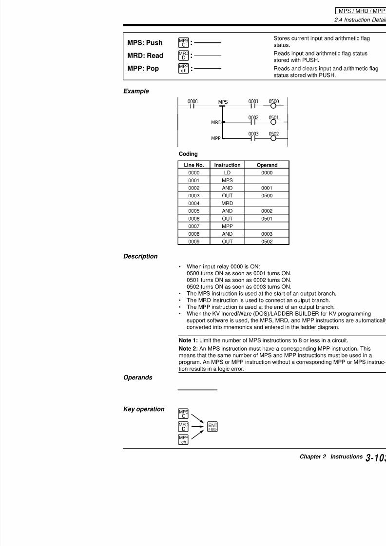
7/18/2019 Keyence Programming
http://slidepdf.com/reader/full/keyence-programming 127/392
Coding
Description
• When input relay 0000 is ON:0500 turns ON as soon as 0001 turns ON.0501 turns ON as soon as 0002 turns ON.0502 turns ON as soon as 0003 turns ON.
• The MPS instruction is used at the start of an outp• The MRD instruction is used to connect an output • The MPP instruction is used at the end of an outpu
• When the KV IncrediWare (DOS)/LADDER BUILDsupport software is used, the MPS, MRD, and MPPconverted into mnemonics and entered in the ladd
Line No. Instruction Operand
0000 LD 0000
0001 MPS
0002 AND 0001
0003 OUT 0500
0004 MRD
0005 AND 0002
0006 OUT 0501
0007 MPP
0008 AND 0003
0009 OUT 0502
0501
0002
0003 0502
MRD
MPP
2.4 Instruction Details
MPS/MRD/MPP applications
MPS, MRD, and MPP instructions are used as follows:
Start of branch0002 0003 0004 0500
0006 0501
0007 0502
MPS
MRD
Connection of branch
Connection of branch
MPS / MRD / MPP

7/18/2019 Keyence Programming
http://slidepdf.com/reader/full/keyence-programming 128/392
2
Coding
Coding
0008 0503MRD
MPP
End of branch
Line No. Instruction Operand Line No. Instruct
0000 LD 0000 0009 MPP
0001 MPS 0010 AND
0000 0001
0004
0002 0500
0003 0501
0005 0502
0006 0503
MPS
MPS
MPS
MPP
MPP
MPP
Line No. Instruction Operand Line No. Instruct
0000 LD 0002 0007 OUT
0001 AND 0003 0008 MRD
0002 MPS 0009 AND
0003 AND 0004 0010 OUT
0004 OUT 0500 0011 MPP
0005 MRD 0012 AND0006 AND 0006 0013 OUT
0000 0001 0002 0003 0004 0500
0501
0502
0503
0504
MPS MPS MPS MPS
MPP
MPP
MPP

7/18/2019 Keyence Programming
http://slidepdf.com/reader/full/keyence-programming 129/392
Coding
MPP
Line No. Instruction Operand
0000 LD 0000
0001 MPS
0002 AND 0001
0003 MPS
0004 AND 0002
0005 MPS
0006 AND 0003
0007 MPS
0008 AND 0004
0009 OUT 0500
0010 MPP
0011 OUT 0501
0012 MPP
0013 OUT 05020014 MPP
0015 OUT 0503
0016 MPP
0017 OUT 0504
2.4 Instruction Details
Example
STG: Stage
JMP: Jump
ENDS: End Stage
Executes instructions in STG block when
When transition condition relay is ON, turns Ostage and transfers execution to stage specif
When transition condition relay is ONof current stage.
ENDS
nnnn
J MP
nnnn
STG
LDB4
LDB4
LDB4
SET1
SET1
ANL2
FUN
FUN
FUN
Initial setting2008 1000
SET
:
:
:
STG / JMP / ENDS
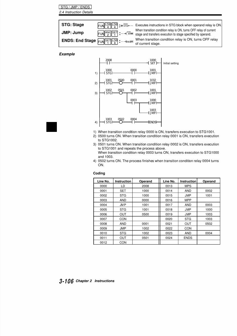
7/18/2019 Keyence Programming
http://slidepdf.com/reader/full/keyence-programming 130/392
21) When transition condition relay 0000 is ON, transfers executio2) 0500 turns ON. When transition condition relay 0001 is ON, tr
to STG1002.3) 0501 turns ON. When transition condition relay 0002 is ON, tr
to STG1001 and repeats the process above.When transition condition relay 0003 turns ON, transfers exec
and 1003.4) 0502 turns ON. The process finishes when transition conditio
ON.
Coding
0000
0500
1001 J MP
1000STG
0001 1002
J MP
1001
STG
0502 0004 ENDS1003STG
0501 0002 1001 J MP
1002STG
0003 1000 J MP
1003 J MP
1)
2)
3)
4)
Line No. Instruction Operand Line No. Instruct
0000 LD 2008 0013 MPS
0001 SET 1000 0014 AND0002 STG 1000 0015 JMP
0003 AND 0000 0016 MPP
0004 JMP 1001 0017 AND
Note 1: The following table shows the status of each JMP/ENDS when STG operand relay turns OFF.
Instruction Function
Relay for OUT instruction Turned OFF.
Relay for OUB instruction Turned ON.
TMR, TMH, TMS, Reset.C (counter) instructions
SET, RES instructions Current status is retain
Other instructions Not executed.
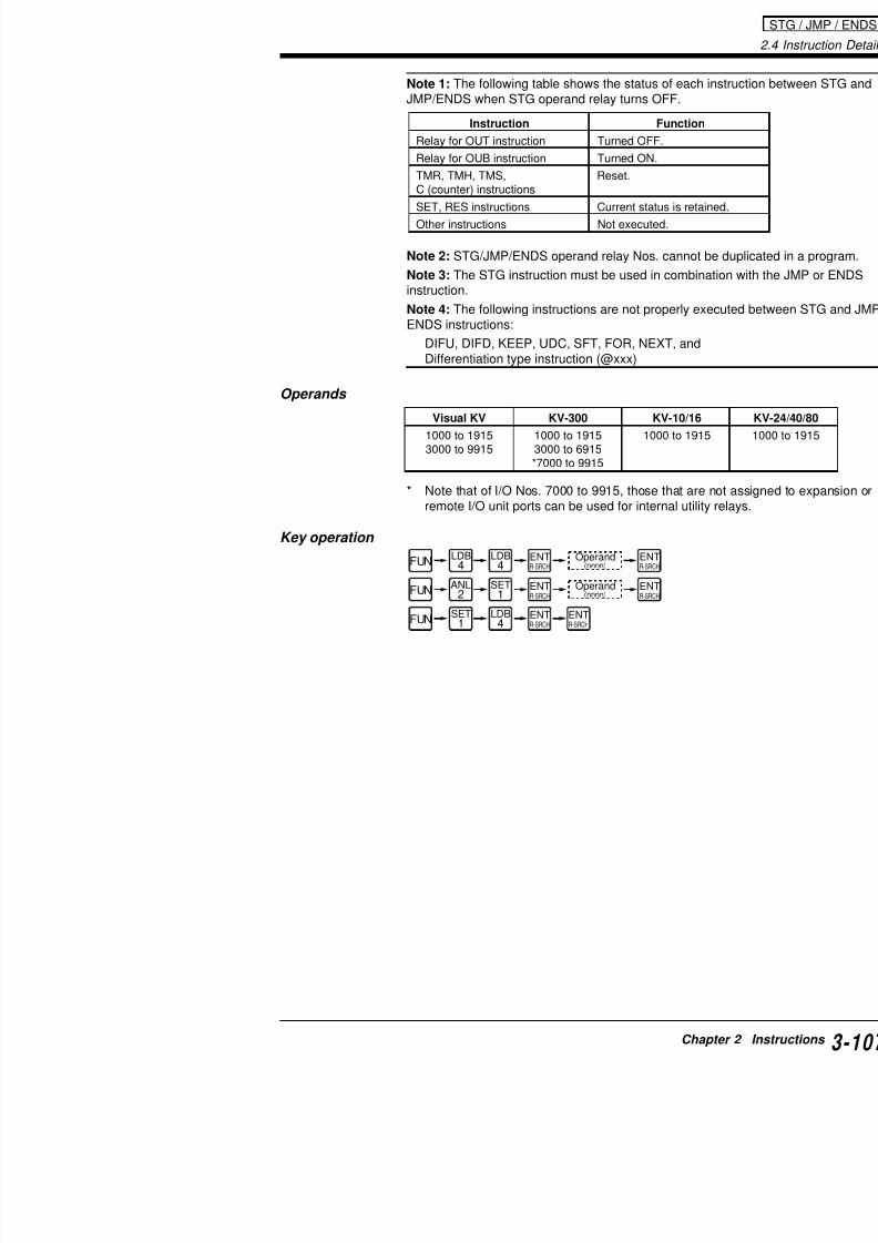
7/18/2019 Keyence Programming
http://slidepdf.com/reader/full/keyence-programming 131/392
Note 2: STG/JMP/ENDS operand relay Nos. cannot b
Note 3: The STG instruction must be used in combinainstruction.
Note 4: The following instructions are not properly exeENDS instructions:
DIFU, DIFD, KEEP, UDC, SFT, FOR, NEXT, andDifferentiation type instruction (@xxx)
Operands
* Note that of I/O Nos. 7000 to 9915, those that are remote I/O unit ports can be used for internal utility
Key operation
FUN
FUN ANL
2
FUN
LDB4
LDB4
LDB4
SET1
SET1
Operand(nnnn)
Operand(nnnn)
ENTR-SRCH
ENTR-SRCH
ENTR-SRCH
ENTR-SRCH
ENTR-SRCH
ENTR-SRCH
Visual KV KV-300 KV-10/16
1000 to 1915 1000 to 1915 1000 to 19153000 to 9915 3000 to 6915
*7000 to 9915
2.4 Instruction Details
Details of STG instruction
STG instruction
The STG instruction is suitable for sequential step-by-step proceThe whole process is divided into several operational steps, and assigned to each step.
The process to turn on several lamps sequentially can be dividedfive steps:
1) Wait until the start switch is turned ON.2) Turn on lamp 1 for 1 second.3) Turn on lamp 2 for 3 second
STG

7/18/2019 Keyence Programming
http://slidepdf.com/reader/full/keyence-programming 132/392
2
3) Turn on lamp 2 for 3 second.4) Turn on lamp 3 for 5 second.5) Turn on lamps 1, 2, and 3 simultaneously for 7 seconds.
These five steps are sequentially performed in order as shown inbelow.If a ladder program is written for such sequential processing withinstructions, the resulting program may be complicated and difficothers.
I/O assignments
Assign the input and output of the Visual KV Series as follows:
1) Start switch: Turned on when 0000 turns ON.2) Lamp 1: Lights when 0500 turns ON.3) Lamp 2: Lights when 0501 turns ON.4) Lamp 3: Lights when 0502 turns ON.
NO
YES
Start
StartSW ON?
Turn on lamp 1for 1 second.
Turn on lamp 2for 3 second.
Turn on lamp 3for 5 second.
Turn on lamps 1, 2,and 3 simultaneouslyfor 7 seconds.
Sequential processing
Sequence program
Assign the relays to execute the five processes on the
1 Wait until the start switch is turned ON.: Input re2 Turn on lamp 1 for 1 second.: Output3 Turn on lamp 2 for 3 second.: Output
4 Turn on lamp 3 for 5 second.: Output5 Turn on lamps 1, 2, and 3 simultaneously: Output
for 7 seconds.
The following is the ladder diagram for the I/O assignmwith and without STG instructions

7/18/2019 Keyence Programming
http://slidepdf.com/reader/full/keyence-programming 133/392
with and without STG instructions.
• Without STG instruction
• With STG instruction
0000 T000
#00010 T000
1000SET
1000
T000 T001 1001
1000
#00030 T001
1001
T001
T003
T002 1002
T002 T003 1100
1101
1102
#00050
T002
#00070 T003
1002
1100
1100
05001000
1101
05011001
1102
05021002
OR circuit is reqdouble coil cann
1000 (0500) turnswhen input 0000 t
1001 (0501) turnswhen T000 turns
1002 (0502) turnswhen T001 turns
1100 (0500), 110(0501), and 1102 turn ON for 7 secowhen T002 turns
The process is rebeginning when T
2.4 Instruction Details
Process progression with Wait instruction
2008
1100
0500
1001 J MP
1000STG
1002 J MP
1001STG
0501 1003 J MP
1002STG
0502
0500 0501 0502
1003STG
1004STG
1004 J MP
1000SET
0000
1100
1101
1102
1103
0000
1101
0000
11020000
1103
STG
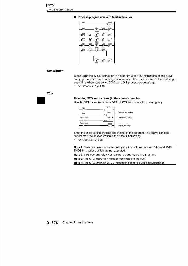
7/18/2019 Keyence Programming
http://slidepdf.com/reader/full/keyence-programming 134/392
2
Description
When using the W-UE instruction in a program with STG instructous page, you can create a program for an operation which moveevery time when start switch 0000 turns ON (process progressio
"W-UE instruction" (p. 3-98)
Tips
Resetting STG instructions (in the above example)
Use the SFT instruction to turn OFF all STG instructions in an em
Enter the initial setting process depending on the program. The acannot start the next operation without the initial setting.
"SFT instruction" (p. 3-82)
Note 1: The scan time is not affected by any instructions betweeENDS instructions which are not executed.
Note 2: STG operand relay Nos. cannot be duplicated in a progr
Note 3: The STG instruction must be connected to the bus.
Note 4: The STG JMP or ENDS instruction cannot be used in s
1104 1000 J MP
0000
1104
2003
2003
SFT
D
1000
CLK
1004
RES
1000SET Initial setting
Reset input
STG start relay
Reset input
STG end relay
Cautions for using STG instruction
Interlock
When an STG instruction moves to another stage, theON simultaneously only for one scan. Provide an interwhich may be dangerous when turned ON in such occ
reverse rotation).
D bl il
0001
0501
0500
1001 J MP
1000STG
1002 J MP
1001STG
0002
0501
0500
Interlock

7/18/2019 Keyence Programming
http://slidepdf.com/reader/full/keyence-programming 135/392
Double coil
A double coil can be used for an STG instruction.
Note: When STG 1000 and 1002 turn ON simultaneorelay 0500 of STG 1002, which is entered last.
Retaining output
Use the SET instruction to retain output.
When no JMP is usedWhen no JMP instruction is used, the STG instruction0001 turns ON. Be sure to use JMP after STG.
STG operand
When the STG operand relay remains ON, 0500 doesturns ON.
Double coil
1100
0501
0500
1001 J MP
1000STG
1002 J MP
1001STG
1101
0001ON
11000002ON
1101
0500 1003 J MP
1002STG
11020003ON
1102
0000
1001
1002
J MP1000STG
J MP
1001STG
0001
0500SET
0501SET
00011000STG
0500 0501
0000 1000
2.4 Instruction Details
JMP operand
Unlike the STG operand relay, the JMP operand relay No. can beprogram.
DIFU/DIFD instructions in an STG block
The operand relay for an STG instruction cannot be used as the
00021001STG
1002 J MP
0501
00011000STG
1001 J MP
1002 J MP
0500
STG / JMP

7/18/2019 Keyence Programming
http://slidepdf.com/reader/full/keyence-programming 136/392
2
The operand relay for an STG instruction cannot be used as the for a DIFU or DIFD instruction.
Application of STG and JMP instructions
Enabling a double coil
When start SW 0000 is pressed, the following output operation is
Output relay 0500 turns ON for 1 second.Output relays 0500 and 0501 turn ON for 2 seconds.Output relays 0500, 0501, and 0502 turn ON for 3 seconds.
Coding
0501
0001
3000
1000STG
3000DIFU
1001 J MP
0500
1100
T000 1001 J MP
1100DIFU
#00010 T000
05001000STG
T001 1002 J MP
#00020 T001
050105001001STG
T002 1000 J MP#00030 T0020502050105001002STG
1000SET
0000
Outputs 0500, 0501, and 0503 seconds.
1000 turns ON at the rising e
Output 0500 turns ON for 1 s
Outputs 0500 and 0501 turn
Line No. Instruction Operand Line No. Instruct
0000 LD 0000 0016 CON
0001 DIFU 1100 0017 TMR
0002 CON 0018 CON
0003 AND 1100 0019 AND
0004 SET 1000 0020 JMP
0005 STG 1000 0021 STG
Note: The double coils in different STG instruction bloever, when several STG instructions turn ON simultanone programmed last.
Conditional branching
When input relay 0000 (start SW) turns ON, output re
programmed for conditional branching, output relay 05when 0001 turns ON, and 0502 turns ON for 2 secondeach operation is completed, the program returns to threpeats the same steps.
11001100 10000000

7/18/2019 Keyence Programming
http://slidepdf.com/reader/full/keyence-programming 137/392
Coding
1100
0001 1001
J MP
1100DIFU
1000
STG
0002 1002 J MP
0500
T000 1000 J MP
#00010 T000
05011001STG
T001 1000 J MP
#00020 T001
05021002STG
1000SET
0000
Line No. Instruction Operand
0000 LD 0000
0001 DIFU 1100
0002 CON
0003 AND 1100
0004 SET 1000
0005 STG 1000
0006 OUT 0500
0007 CON
0008 MPS
0009 AND 0001
0010 JMP 1001
0011 MPP
0012 AND 00020013 JMP 1002
0014 STG 1001
2.4 Instruction Details
Example
STP: Step
STE: Step End
Executes instructions betwSTE when operand relay i
Used with STP to make a
LDB4
LDB4
ANB5
ORL3
STE
STPnnnnFUN
FUN
STP1000
0001 0500
0000 1000
:
:
STP / STE
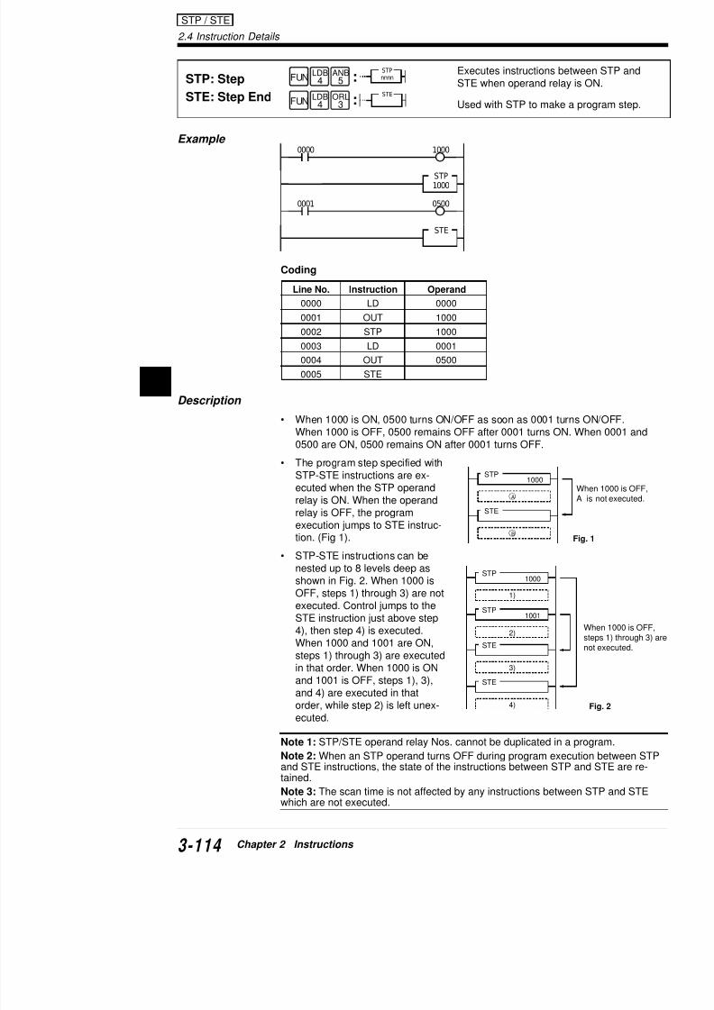
7/18/2019 Keyence Programming
http://slidepdf.com/reader/full/keyence-programming 138/392
2
1000STP
STP1001
1)
Coding
Description
• When 1000 is ON, 0500 turns ON/OFF as soon as 0001 turnsWhen 1000 is OFF, 0500 remains OFF after 0001 turns ON. W0500 are ON, 0500 remains ON after 0001 turns OFF.
• The program step specified withSTP-STE instructions are ex-ecuted when the STP operandrelay is ON. When the operandrelay is OFF, the programexecution jumps to STE instruc-tion. (Fig 1).
• STP-STE instructions can benested up to 8 levels deep as
shown in Fig. 2. When 1000 isOFF, steps 1) through 3) are notexecuted. Control jumps to theSTE instruction just above step
STE
Line No. Instruction Operand
0000 LD 0000
0001 OUT 1000
0002 STP 1000
0003 LD 0001
0004 OUT 05000005 STE
1000STP
STE
A
BF
Tips
Operation when STP turns OFF
Using a timer in an STP block
When a timer is used in a program defined with an STas follows:
a) 1000 is reset immediately when thetimer turns ON. The STE instruction isstarted with the timer remaining ON.
0000
T000
a)

7/18/2019 Keyence Programming
http://slidepdf.com/reader/full/keyence-programming 139/392
b) 1000 is not reset immediately when thetimer turns ON but is reset at the nextscan. The timer is reset before the STEinstruction is started.
Usage of STG and STP instructions
STG instructionUse the STG instruction for process progression with
STP instruction
1000
T000
0000
T000
T000
1000
b)
0000
ENDS
ENDS
1002
J MP
1001
J MP
1000
STG
1001
STG
1002
STG
0001
0002
0003
0004
0500
0501
0502
1000SET
2.4 Instruction Details
Operands
* Note that of I/O Nos.7000 to 9915, those that are not assigned to exunit ports can be used for internal utility relays.
Key operation
STP / STE
Visual KV KV-300 KV-10/16 KV
0000 to 17915 0000 to 0009 0000 to 2915 000T000 to T249 0500 to 6915 T000 to T063 T00C000 to C249 *7000 to 9915 C000 to C063 C00CTC0 to CTC3 T000 to T249 CTC0 to CTC3 CTC
C000 to C249CTC0 to CTC3

7/18/2019 Keyence Programming
http://slidepdf.com/reader/full/keyence-programming 140/392
20000 1000
T000
1001SET
T000
1001
T000
1001RES
0500
0501
1002RES
STE
STP1002
STP1001
1002SET
1000DIFU
#00020 T000
1002
T001
T001
#00030 T001
Line No. Instruction
0000 LD
0001 DIFU
0002 CON
0003 AND
0004 SET
0005 STP0006 LD
0007 RES
0008 LDB
0009 OUT
0010 LD
0011 TMR
0012 LD
0013 SET
0014 STE0015 STP
0016 LD
0017 RES
Application of STP and STE instructions
Process progression
When input relay 0000 turns ON, output relay 0500 turns ON for
output relay 0501 turns ON for 3 seconds automatically.Coding
FUN
FUN
LDB4
LDB4
ANB5
ORL3
Operand(nnnn)
ENTR-SRCH
ENTR-SRCH
ENTR-SRCH ENTR-SRCH
Example
ITVL: Interval Timer Measures pulse-width in specified
ITVLPLSDMnnnnPAUSEmmmmRES
ITVL#TM
0000
0001
0002
PLS
DM0000
PAUSE
1000
RES
ITVL
"Pulse" input
Beginning of workpiece data table
"Measurement Pause" inputFirst flag relay
:

7/18/2019 Keyence Programming
http://slidepdf.com/reader/full/keyence-programming 141/392
Coding
Operation in the above example
Measures pulse-to-pulse interval or pulse width for inpITVL instruction has two functions:• Measures pulse-to-pulse interval (cycle) or pulse w• Obtains the average of the contents of data memo
Each input has the following functions:• PLS
Executes measurement. In data memory measuredisabled in modes 0006 to 1999. Values are fetche
input is ON in modes 10000 to 11999.The measured value is written into the specified da
In the above example, the measured vwritten into DM0004 (DM0000 + 4 add
• PAUSEPauses the measurement when turned ON.
• RES
Initializes the contents of data memory (DM) when In the above example, DM0004 to DM0015 are
• DM0000 to DM0003 are designated as the area to
"Reset" input
Line No. Instruction Operand
0000 LD 0000
0001 LD 0001
0002 LD 0002
0003 ITVL DM0000 1000
2.4 Instruction Details
Setting procedure
The ITVL instruction reserves 16 data memories: 1 specified datasuccessive data memories. It also reserves 4 relays: 1 specified sive relays.
Note: Do not use the 16 data memories and 4 relays specified w
tion for any other purpose.
Data memory (DM) assignment
• Set the initial setting data to the first four data memories.
Data memory
ITVL
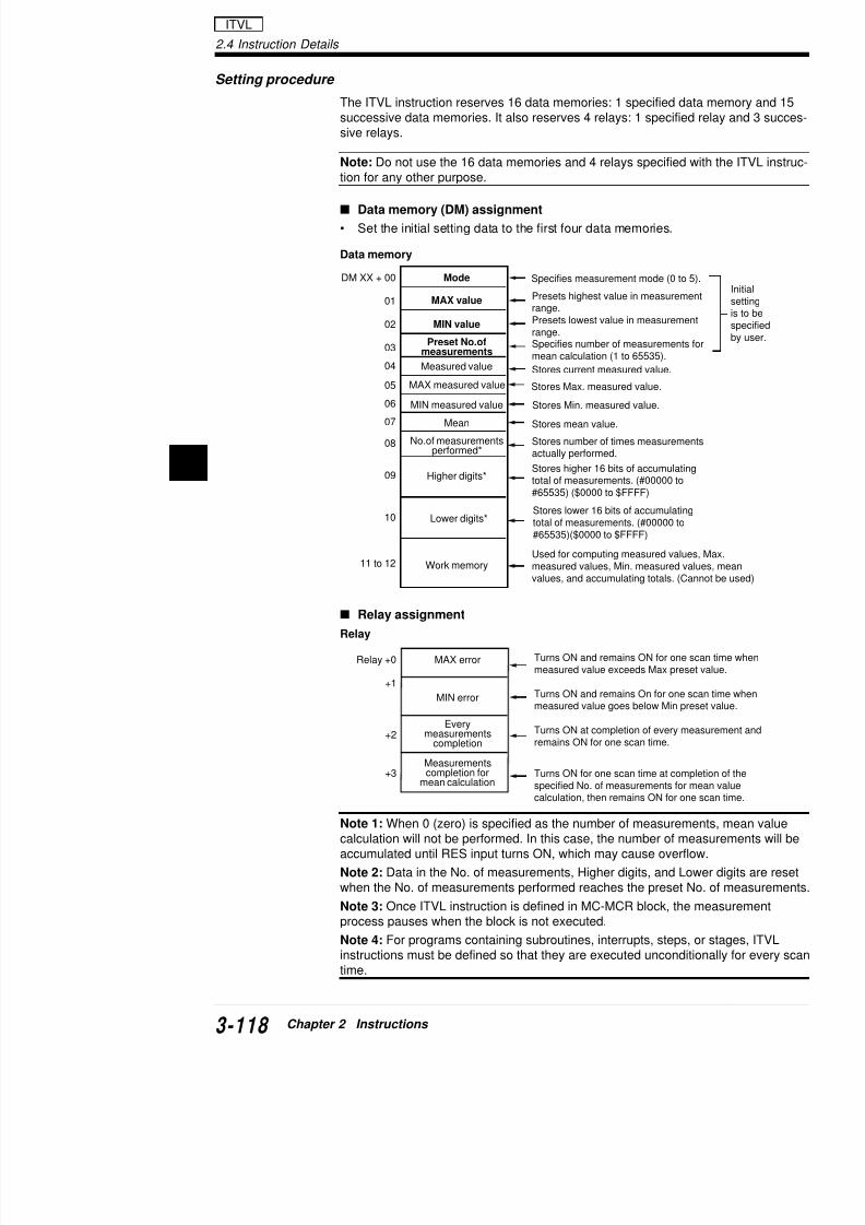
7/18/2019 Keyence Programming
http://slidepdf.com/reader/full/keyence-programming 142/392
2
ModeDM XX + 00
01
02
03
04
05
06
07
08
09
10
11 to 12
MAX value
MIN value
Measured value
MAX measured value
MIN measured value
Mean
Preset No.ofmeasurements
No.of measurementsperformed*
Higher digits*
Lower digits*
Work memory
MAX errorRelay +0
+1
+2
MIN error
Everymeasurements
completion
Used for computing measured valuesmeasured values, Min. measured valuvalues, and accumulating totals. (Can
Specifies measurement mode (0 to 5)
Presets highest value in measuremen
range.Presets lowest value in measurementrange.Specifies number of measurements fomean calculation (1 to 65535).
Stores current measured value.
Stores Max. measured value.
Stores Min. measured value.
Stores mean value.
Stores number of times measurementactually performed.
Stores higher 16 bits of accumulatingtotal of measurements. (#00000 to#65535) ($0000 to $FFFF)
Stores lower 16 bits of accumulatingtotal of measurements. (#00000 to#65535)($0000 to $FFFF)
Turns ON and remains ON for one scmeasured value exceeds Max preset
Turns ON and remains On for one sc
measured value goes below Min pres
Turns ON at completion of every mearemains ON for one scan time.
Relay assignment
Relay
Mode setting
Write the desired mode No. into the first data memory
Mode for pulse measurement
ModePulse-to-pulse
interval Unit Mode
10 m sec
100 m sec
1
Pulse-to-pulse interval measurement Puls
0 1
2 3
4 5

7/18/2019 Keyence Programming
http://slidepdf.com/reader/full/keyence-programming 143/392
Mode for DM measurementWrite the desired mode No. into the specified data me
Example
Write "#0006" to obtain the average of the contents of
Note 1: When the mode No. is set to 10000 through 1the scan only when the PLS input relay is ON.
Note 2: When the average of a data memory is calcul"65535" are converted into corresponding compliment
Note 3: Some data memories after DM1000 are assig
1 sec
Mode No. DM No.
10000 DM0000Measure the coaverage.
10001 DM0001Measure the coaverage.
• • •• • •
10005 DM0005 Measure the coaverage.
000610006 DM0006
Measure the coaverage.
0007 10007 DM0007 Measure the coaverage.
• • • •• • • •
1999 11999 DM1999 Measure the coaverage.
2000 to 9999 12000 or more Not provided Cannot be use
4 5
2.4 Instruction Details
Application of ITVL instruction
This section describes examples of pulse interval measurement.
Pulse interval measurement
Turns ON output relay 0500 for 3 seconds when the pulse intervarange of 490 to 510 ms.
2008
2008
2008
#00000LDA
DM0000STA
#00051LDA
DM0001STA
#00049 DM0002
Sets mode 0 (Unit:10 ms).
Sets max. setting value of measurement range to 5
ITVL

7/18/2019 Keyence Programming
http://slidepdf.com/reader/full/keyence-programming 144/392
2
Coding
2008
2008
0000
0001
0002
T0001000
1001
0500
#00049LDA
DM0002STA
#00010
LDA
DM0003
STA
PLS
DM0000
PAUSE
1000
RES
ITVL
0500
#00030 T000
Line No. Instruction Operand Line No. Instruct
0000 LD 2008 0013 LDA
0001 LDA #00000 0014 CON
0002 CON 0015 STA
0003 STA DM0000 0016 LD
0004 LD 2008 0017 LD
0005 LDA #00051 0018 LD
0006 CON 0019 ITVL
0007 STA DM0001 0020 LD0008 LD 2008 0021 OR
0009 LDA #00049 0022 OR
1001 turns ON for one scan when measured valueis below min. setting value (490 ms).
Sets min. setting value of measurement range to 49
Sets number of averaging measurements to 10.
Measures pulse interval when input relay 0000 turn
Pauses measurement while input relay 0001 turns O
Resets measurement when input relay 0002 turns O
1000 turns ON for one scan when measuredvalue exceeds max. setting value (510 ms).
A/D data measurement
Turns ON output relay 0500 when the analog input fro(range: 1 to 5 V) exceeds +3 V. Turns ON output relay+2 V. Writes the average into DM0100.Refer to the "KL-4AD/KL-2AD User’s Manual" for data4AD.
2008
2008
2008
#01600LDA
DM0000STA
#02000LDA
DM0001STA
#01000 DM0002
Measures contents of DM1600.
Sets max. setting value to +3 V (20
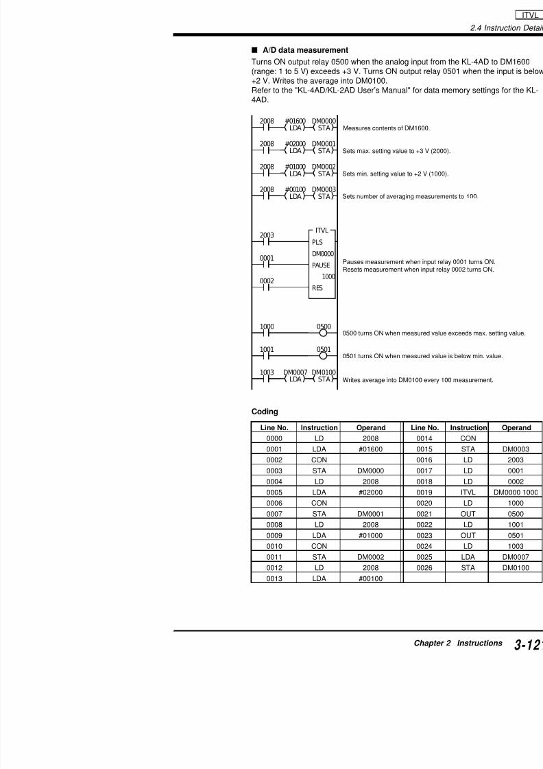
7/18/2019 Keyence Programming
http://slidepdf.com/reader/full/keyence-programming 145/392
Coding
2008
2003
0001
0002
1000
LDA STA
#00100LDA
DM0003STA
PLS
DM0000
PAUSE
1000RES
ITVL
1001
1003 DM0100STA
DM0007LDA
0500
0501
Writes average into DM0100 every
Sets min. setting value to +2 V (10
Sets number of averaging measure
Pauses measurement when input Resets measurement when input r
0500 turns ON when measured va
0501 turns ON when measured va
Line No. Instruction Operand Line No.
0000 LD 2008 0014
0001 LDA #01600 0015
0002 CON 0016
0003 STA DM0000 0017
2.4 Instruction Details
Example
CALL: Subroutine Call
SBN: Subroutine Entry
RET: Subroutine Return
Executes subroutine spe
Represents beginning offied by operand.
Represents end of subro
RES0
RES0
AND8
ORL3
ORL3
ORL3
FUN
FUN
FUNRET
SBNnn
CALLnn
0000 00CALL
END
:
:
:
CALL / SBN / RET
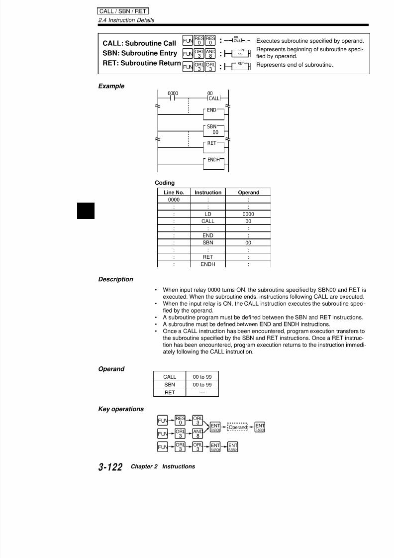
7/18/2019 Keyence Programming
http://slidepdf.com/reader/full/keyence-programming 146/392
2
Coding
Description
• When input relay 0000 turns ON, the subroutine specified by executed. When the subroutine ends, instructions following C
• When the input relay is ON, the CALL instruction executes thefied by the operand.
• A subroutine program must be defined between the SBN and• A subroutine must be defined between END and ENDH instruct• Once a CALL instruction has been encountered, program exe
the subroutine specified by the SBN and RET instructions. On
Line No. Instruction Operand
0000 : :: : :
: LD 0000
: CALL 00
: : :
: END :
: SBN 00
: : :
: RET :
: ENDH :
SBN00
RET
ENDH
Application of subroutine
00
CALL
SBN00
2008
RET
END
B)
A)
Subroutine program
Normal scan
Subroutine
Program
Program

7/18/2019 Keyence Programming
http://slidepdf.com/reader/full/keyence-programming 147/392
When CALL00 is encountered during normal scan exeexecuted. At the completion of this subroutine, progragram at B) immediately following CALL00. Then, the nan END instruction is encountered.
With no CALL instruction With CALL instru
Nesting structure of a subroutine
• Subroutine instructions can be nested up to 4 leve• A subroutine which is called from another subrouti
the call.
00
CALL
0000
A)
B)
ENDH
Program
Program
0000
B
AProgram
Program
00CALL
0001
END
Program
2.4 Instruction Details
Calling a subroutine from an interrupt program
• Subroutines can be called from interrupt programs.• A subroutine which is called from an interrupt program should
the call.
SBN00
0001
RET
END
0500
Program
Subroutine program
CALL / SBN / RET

7/18/2019 Keyence Programming
http://slidepdf.com/reader/full/keyence-programming 148/392
2
Note 1: Subroutine Nos. for SBN instructions cannot be duplicate
(It can be duplicated for CALL instructions.)Note 2: When a subroutine is executed, the scan time is extendeneeded for subroutine execution.
Note 3: The following instructions cannot be used in subroutinesSTG, JMP, ENDS, INT, RETI, and MEMSW
Note 4: The following instructions can be used only in subroutineecuted every scan time:
TMR, TMH, TMS, C, SFT, UDC, DIFU, DIFD, W-UE, W-DE, HK
and Differentiation type instruction (@xxx)
00CALL
0002
INT
0000
ENDH
RET
RETI
Call
Example
FOR: Repeat Start
NEXT: Repeat End
Executes progby number of
Represents e
FUN
FUN
SET1
ANL2
OR9
ORB6
NEXT
FORnnnn
2008 00CALL
END
SBN00
:
:

7/18/2019 Keyence Programming
http://slidepdf.com/reader/full/keyence-programming 149/392
Coding
Line No. Instruction Operand Line No
0000 LD 2008 0107
0001 CALL 00 0108
: : 0109
0099 END 0110
0100 SBN 00 0111
0101 LD 2002 0112
0102 LDA #00100 0113
0103 CON0104 STA TM02
0105 CON
LDA
Specify the first DM No.
Specify the number of DMs to beinitialized.
#00100
LDA
2002
2002
#00050FOR
NEXT
RET
ENDH
TM02
STA
#00000
LDA
#TM02STA
TM02INC
(DM100)
2.4 Instruction Details
Tips
Note 1: The FOR-NEXT instruction pair repeats the program for period at each scan. It usually is used in steps or subroutines.
Note 2: When a large number of loops or long programs are defiand NEXT instructions, the processing time for one scan may beresulting in "Cycle time error". In such a case, reduce the numbe
the ladder program.
• The FOR-NEXT instruction set can be nested up to 8 levels dnested levels will result in a FOR-NEXT error.
FOR#05
FOR / NEXT
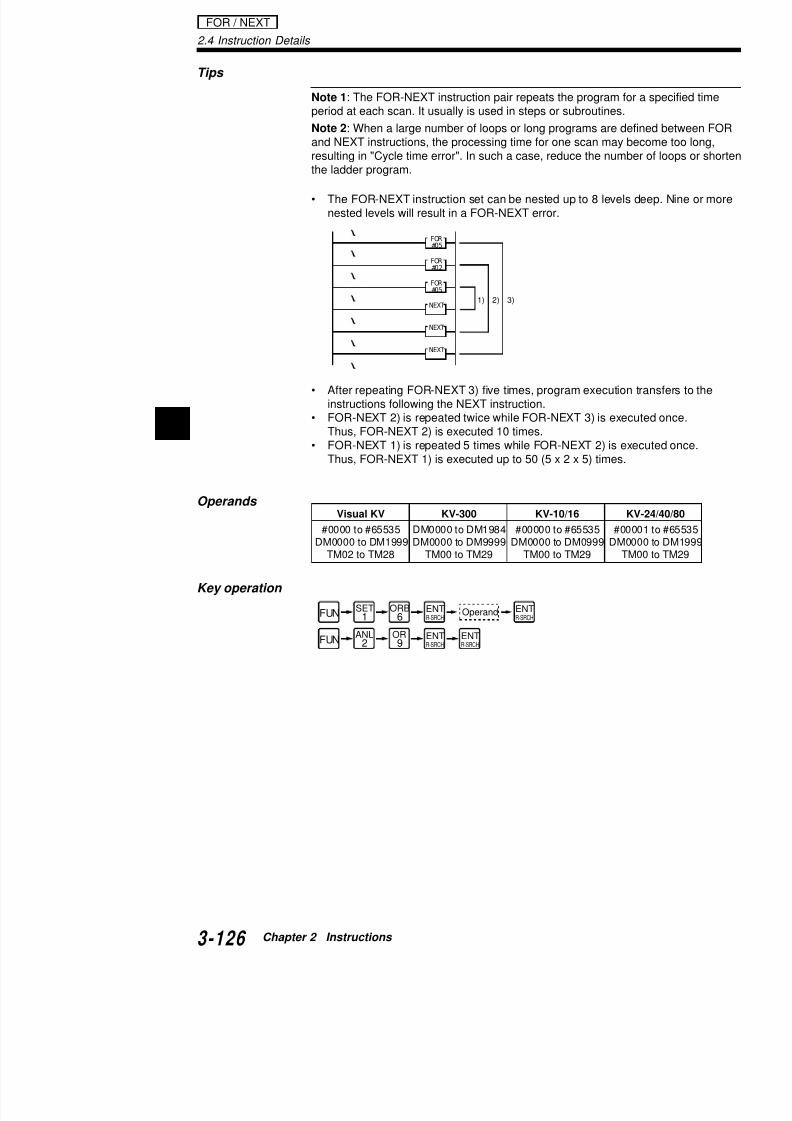
7/18/2019 Keyence Programming
http://slidepdf.com/reader/full/keyence-programming 150/392
2
• After repeating FOR-NEXT 3) five times, program execution t
instructions following the NEXT instruction.• FOR-NEXT 2) is repeated twice while FOR-NEXT 3) is execu
Thus, FOR-NEXT 2) is executed 10 times.• FOR-NEXT 1) is repeated 5 times while FOR-NEXT 2) is exe
Thus, FOR-NEXT 1) is executed up to 50 (5 x 2 x 5) times.
Operands
Key operation
NEXT
NEXT
NEXT
FOR#05
FOR#02
1) 2) 3)
FUN
FUN
SET1
ANL
2
OR
9
ORB6
OperandENTR-SRCH
ENTR-SRCH
ENT
R-SRCH
ENT
R-SRCH
Visual KV KV-300 KV-10/16 KV
#0000 to #65535 DM0000 to DM1984 #00000 to #65535 #0000DM0000 to DM1999 DM0000 to DM9999 DM0000 to DM0999 DM000
TM02 to TM28 TM00 to TM29 TM00 to TM29 TM0
Indirect addressing
Indirect addressing
Indirect addressing is used to so you don't have to useNos. when the contents of data memory or a relay is swhen the contents of the internal memory is stored in
Method for indirect addressing
• Specify the operand for instructions as "#TMxx". Tconsidered to be the specification No. (indirect add
Example
When TM02 value is "0000", "#TM02" represents DWhen TM02 value is "10000", "#TM02" represents

7/18/2019 Keyence Programming
http://slidepdf.com/reader/full/keyence-programming 151/392
, p
• Any of "02" through "29" can be specified for "xx".
• Specify the desired decimal number for "xx".• Numbers "0000" through "1999" specify DM0000 t
memory).Numbers "10000" through "27915" specify 0000 th
Example: LDA #TM15
This is the same operation whether "LDA DM0020" orspecified data memory or relay can be changed as deTM15.
Example: STA #TM02
This is the same operation whether "STA DM0000" orspecified data memory or relay can be changed as deTM02.
Range of DM and relay Nos. that can be specifi
TM15 value Data entered into internal register
20 DM0020
11000 1000 to 1015
TM02 value Specified destination
00 DM0000
13000 3000 to 3015
TMxx value DM/relay0000 to 1999 DM0000 to DM1999
2000 to 9999 Cannot be used.
2.4 Instruction Details
Data memory block transfer
DM0000
DM0099
DM0100
DM0199
•
•
•
•
•
•
•
•
•
•
•
•
The block transferred
The contents of DM0000 aretransferred to DM0100.
The contents of DM0099 aretransferred to DM0199.
Transfer ablock of
data.
FOR / NEXT

7/18/2019 Keyence Programming
http://slidepdf.com/reader/full/keyence-programming 152/392
2
• Comparison between a program with normal addressing and addressing.
Program with normal addressing Program with indirect add
0000
1000
1000
1000
1000
DM0000LDA
DM0100STA
DM0001LDA
DM0101STA
DM0002LDA
DM0102STA
DM0003LDA
DM0103STA
1000 DM0098LDA
DM0198STA
1000 DM0099LDA
DM0199STA
1000
DIFU
END
ENDH
0000
1000
2002 #00000LDA
TM02STA
#00100LDA
T
2002 #TM02LDA
#TM03STA
TM02INC
T
#
N
E
1
C
The contents of DM0000 are transferredto DM0100.The contents of DM0001 are transferredto DM0101.The contents of DM0002 are transferredto DM0102.
••
•••
The contents of DM0099 are transferredt DM0199
Program stepsare reduced byone-eighth.
The first No. of the source D(DM0000).The first No. of the destinatio(DM0100).The contents of the DM indi"#TM02" is transferred to the
The contents of the internal to the DM indirectly address
Add "1" to both "TM02" and the Nos of the source and d
Description
• On line 1), "TM02" is assigned to the first No. of thassigned to the first No. of the destination 0100. Th
• On lines 2) to 4), the contents of DM0000 to DM00to DM0199.
• The ladder program on line 3) is executed 100 time
1st operation: TM02 value: 0000, TM03 value: 0100
2002 #TM02LDA
#TM03STA
T
DM0000 isindirectlyaddressed
DM0100 isindirectlyaddressed.
Addcurr"TM

7/18/2019 Keyence Programming
http://slidepdf.com/reader/full/keyence-programming 153/392
2nd operation: TM02 value: 00001, TM03 value: 0101
100th operation: TM02 value: 0099, TM03 value: 0199
When the ladder program on line 3) is repeated 100 tispecified DM block are transferred.
This operation is repe
2002 #TM02LDA
#TM03STA
T
2002 #TM02LDA
#TM03STA
T
•
•
•
•
addressed.
DM0001 isindirectlyaddressed.
DM0101 isindirectlyaddressed.
Addcur"TM
DM0099 isindirectlyaddressed.
DM0199 isindirectlyaddressed.
Adcuof
2.4 Instruction Details
Application of SBN-RET and FOR-NEXT instructions
Data memory shift
Shifts the contents of the current data memory (DM) to the next Dedge of the synchronous (timing) signal. As the number of DMs tcreases, the required scan time becomes longer.
0000 1000
2002
#00010LDA
TM03LDA
TM04STA
TM02SUB
TM05STA
#00001ADD
TM02STA
#00030 TM03LDA STA
00CALL
1000DIFU
END
SBN00
FOR
Synchronoussignal
Shift start DMNo. (DM0010)is designated.
Shift end DMNo. (DM0030)is designated.
Shift level
Data is shifted fromDM0030.
FOR / NEXT

7/18/2019 Keyence Programming
http://slidepdf.com/reader/full/keyence-programming 154/392
2 Coding
2002 TM03DEC #TM03LDA #TM04STA TM04DEC
NEXT
FOR
2002 #00000LDA
#TM02STA
RET
TM05
ENDH
Shift level
Indirect addressing is usedto designate DM Nos.
Program lines whichdata shift are groupsubroutine.
Shift start DM No. is cleared to"#00000" after data is shifted.
Line No. Instruction Operand Line No. Instruct
0000 LD 0000 0020 STA
0001 DIFU 1000 0021 CON
0002 CON 0022 SUB
0003 AND 1000 0023 CON
0004 LDA #00010 0024 STA
0005 CON 0025 FOR
0006 STA TM02 0026 LD
0007 CON 0027 DEC
0008 LDA #00030 0028 CON
0009 CON 0029 DEC
0010 STA TM03 0030 CON
0011 CON 0031 LDA0012 CALL 00 0032 CON
0013 END 0033 STA
HKEY: 16-Key InputReads hexadecsharing basis aspecial utility re
FUN SET
1LD7
HKEYnnnn
mmmm
0005 HKEY00000500
Input relay
Output relay
:
Example
Coding

7/18/2019 Keyence Programming
http://slidepdf.com/reader/full/keyence-programming 155/392
Line No. Instruction Operand
0000 LD 00050001 HKEY 0000 0500
COM24VDC
+
-
000 001KV
002 003
0
COM 500 501 502 503
4
8
C
1
5
9
D
2
6
A
E
3
7
B
F
Description
• When input relay 0005 turns ON, the operand hexa• HKEY instruction employs four inputs and four outp
Refer to "Fetching 16-key input" (p. 3-133) for the programming
• The HKEY instruction employs four input relays anspecified number.
• Inputs are processed on a time-sharing basis, so thscan time cycles (approx. 160 msec when the scan
• When a hexadecimal key is pressed, the HKEY inssponding special utility relay (2900 to 2915).
2.4 Instruction Details
HKEY
Note 4: When two or more keys are pressed simultaneously evescan while relay 2814 is ON, relays 2900 through 2915 keep the soon as relay 2815 turns ON.
Note 5: The HKEY instruction does not properly operate if the scthan 200 ms.
Note 6: When the expansion I/O module is used as an operand,
unless the scan time is fixed to 2 ms or longer.
Operands
Visual KV KV-300 KV-10/16/
Input relay Output relay Input relay Output relay Input relay
0000 to 0500 to 00000 to 00500 to 0000 to 0415 0915 00009 00503 0415
10000 t 10500 t

7/18/2019 Keyence Programming
http://slidepdf.com/reader/full/keyence-programming 156/392
2
2002 0001 C000
2815
0005
#09999C0000000
HKEY01040512
ENDH
END
2900LDA TBIN
C000STA
0600
FUN SET
1LD7 Output relayInput relay ENT
R-SRCHENTR-SRCH
Key operation
Application of HKEY instruction
Changing the preset value of internal counters using a BC
Coding
Line No. Instructio
0000 LD
0001 ANB0002 C
0003 CON
0004 AND
0005 OUT
0006 LD
0007 HKEY
0008 LD
0009 LDA
0010 CON
0011 TBIN
0012 CON
10000 to 10500 to10415 10915
: :17000 to 17500 to17415 17915
COM24VDC
+
-
0104 0105KV
0106 01071
100 101 102
2 4 8
COM 0512 0513 0514 0515
BCD Digital switch
Diode

7/18/2019 Keyence Programming
http://slidepdf.com/reader/full/keyence-programming 157/392
2815
2002
2008
2010 20102900
LDA
$03FF
ANDA
TM05
CMP
TM05CMP
TM05
STA
TM06
STADMX
2815
2815 2915
2010 2010
DM0000STA
#00000
DM0000DW
TM06STA
#04SLA
DM0000LDA
2900LDA
$03FFANDA
TM05STA
END
ENDH
2814SET
HKEY
05000000
Line No. Instruction Operand Line No
0000 LD 2008 0020
0001 SET 2814 0021
0002 LD 2002 0022
0003 HKEY 0000 0500 0023
0004 LD 2815 00240005 LDA 2900 0025
0006 CON 0026
Fetching 16-key input
Writes the following 16-key input value into DM0000 aPressing the [F] key clears the input value.
Coding
2.4 Instruction Details
2.4.3 Arithmetic Instructions
Arithmetic instructions handle data as integers to perform arithmelogical operations.
Instruction Mnemonic
DW: Data Memory Write DW
Trimmer In TMIN (FUN50), @TMIN @(FUN50)
LDA/@LDA: Load A LDA (FUN23), @LDA@ (FUN23)
STA/@STA: Store A STA (FUN42), @STA@ (FUN42)
CMP/@CMP: Compare CMP (FUN04), @CMP @(FUN04)
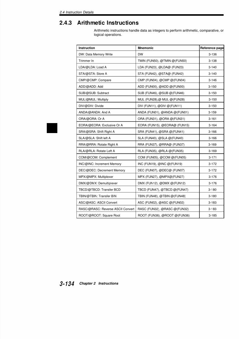
7/18/2019 Keyence Programming
http://slidepdf.com/reader/full/keyence-programming 158/392
2
p ( ) ( )
ADD/@ADD: Add ADD (FUN00), @ADD @(FUN00)
SUB/@SUB: Subtract SUB (FUN46), @SUB @(FUN46)
MUL/@MUL: Multiply MUL (FUN28),@ MUL @(FUN28)
DIV/@DIV: Divide DIV (FUN11), @DIV @(FUN11)
ANDA/@ANDA: And A ANDA (FUN01), @ANDA @(FUN01)
ORA/@ORA: Or A ORA (FUN31), @ORA @(FUN31)
EORA/@EORA: Exclusive Or A EORA (FUN15), @EORA@ (FUN15)
SRA/@SRA: Shift Right A SRA (FUN41), @SRA @(FUN41)
SLA/@SLA: Shift left A SLA (FUN40), @SLA @(FUN40)
RRA/@RRA: Rotate Right A RRA (FUN37), @RRA@ (FUN37)
RLA/@RLA: Rotate Left A RLA (FUN35), @RLA @(FUN35)
COM/@COM: Complement COM (FUN05), @COM @(FUN05)
INC/@INC: Increment Memory INC (FUN19), @INC @(FUN19)
DEC/@DEC: Decrement Memory DEC (FUN07), @DEC@ (FUN07)
MPX/@MPX: Multiplexer MPX (FUN27), @MPX@(FUN27)
DMX/@DMX: Demultiplexer DMX (FUN12), @DMX @(FUN12)
TBCD/@TBCD: Transfer BCD TBCD (FUN47), @TBCD @(FUN47)
TBIN/@TBIN: Transfer BIN TBIN (FUN48), @TBIN @(FUN48)
ASC/@ASC: ASCII Convert ASC (FUN02), @ASC @(FUN02)
Internal register
KV executes all arithmetic instructions (i.e. data excharegister, in order to increase the processing speed.This section begins by describing details of the interna
Internal register
An internal register stores 16-digit binary data. That isstoring ON-OFF status data (1-0 status data). The intethe KV performs arithmetic operation. Because this is it is not necessary to take into consideration how the ioperates.
Arithmetic instructions executed using interna

7/18/2019 Keyence Programming
http://slidepdf.com/reader/full/keyence-programming 159/392
1. ON-OFF status of the specified relay and 15 succe
resister.2. Current T/C value (decimal value = #*****) is autombinary value and input to the internal register.
3. Constant (decimal value = #*****, hexadecimal valconverted into a binary value and input to the inter
4. The range of numbers that can be specified is as fDecimal #00000 to #65535Hexadecimal $0000 to $FFFF
The constants can be entered by using @#, $ and the
keys.(Pressing @
#, $ once allows you to enter decimal valuhexadecimal values.)
D15 D14 D13 D12 D11 D10 D9 D8 D7 D6 D5 D4 D3
(Arithmetic instructions executed as binary code.)
Relay No.1.Current T/Cvalue. 2.
Constant 3. 4.
(decimal,hexadecimal)
Data memory,temporarymemory
LDA instruction
Internal registerSTA direction
Relay NoPreset T/Cvalue. 5.
Data memory,temporarymemory
Data mein indiretempora
2.4 Instruction Details
Example
Coding
DW: Data Memory Write Directly writes constant iDW nnnn
DMmmmmDW
2008 #00050DM0001
DW$0018DM0000
DW
Line No. Instruction Operand
0000 LD 2008
:
First operand
Second operand
DW
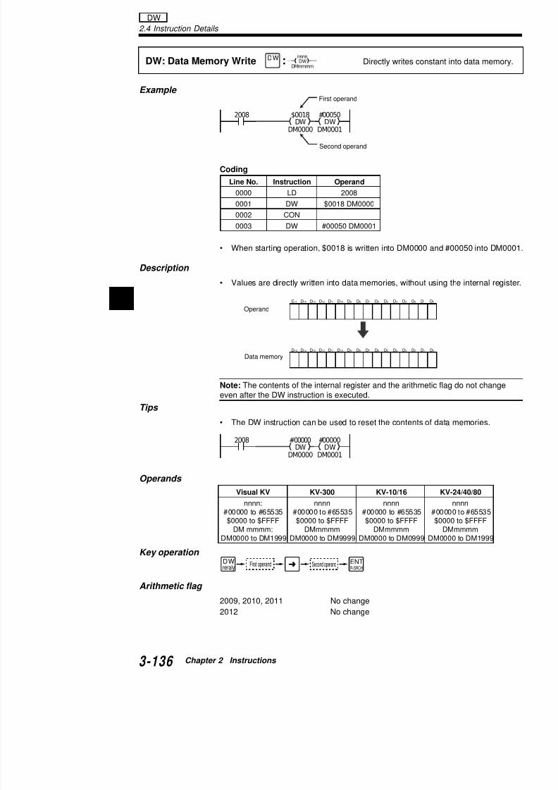
7/18/2019 Keyence Programming
http://slidepdf.com/reader/full/keyence-programming 160/392
2
• When starting operation, $0018 is written into DM0000 and #
Description
• Values are directly written into data memories, without using
Note: The contents of the internal register and the arithmetic flageven after the DW instruction is executed.
Tips
• The DW instruction can be used to reset the contents of data
Operands
0000 LD 2008
0001 DW $0018 DM00000002 CON
0003 DW #00050 DM0001
D15 D14 D13 D12 D11 D10 D9 D8 D7 D6 D5 D4 D3 D2 D1 D0
D15 D14 D13 D12 D11 D10 D9 D8 D7 D6 D5 D4 D3 D2 D1 D0
2008 #00000
DM0001
DW#00000
DM0000
DW
Operand
Data memory
Example
Description
• Arithmetic instructions have two instruction types: dscan type.
• The differentiation type instruction is executed onlyrelay 0000.
@xxxx: DifferentiationExecutes instrinput to input
@#,$ FUN xxxx
0000 0000 DM0000INC
Every-scan type instrDifferentiation type instruction
:

7/18/2019 Keyence Programming
http://slidepdf.com/reader/full/keyence-programming 161/392
y
• The every-scan type instruction is executed every 0000 is ON.
Timing diagram
• Instructions with the DIFFERENTIATION function LDA, SAT, CMP, ADD, SUB, MUL, DIV, ANDA, ORRLA, COM, INC, DEC, MPX, DMX, TBCD, TBIN, A
Note:In the executhe coinput r
In the tion is DM00
relay 0
ONOFF0000
INC
ONOFF0000
INC
Diffe
Executed StoppedStopped Stopp
Every-scan type instruction
0000 DM0000INC
0000 DM0000INC
0000 1000 DM00001000
2.4 Instruction Details
T000 preset value can be changed with trimmer as follows (#000
TMIN: Trimmer In
@TMIN: Trimmer Setting
Inputs numerical value strimmer of access windowinternal register.@
#,$
FUN
FUN RES
0ANB
5
RES0
ANB5
n TMIN
n TMIN
Inputs trimmer rotation angle of 0 to internal register.
Transfers contents of internal register to timfor use as preset value.
Turns ON output 0500 when current value
02002
TMIN
T000
STA
#000100000 T000 0500
T000
:
:
TMIN / @TMIN
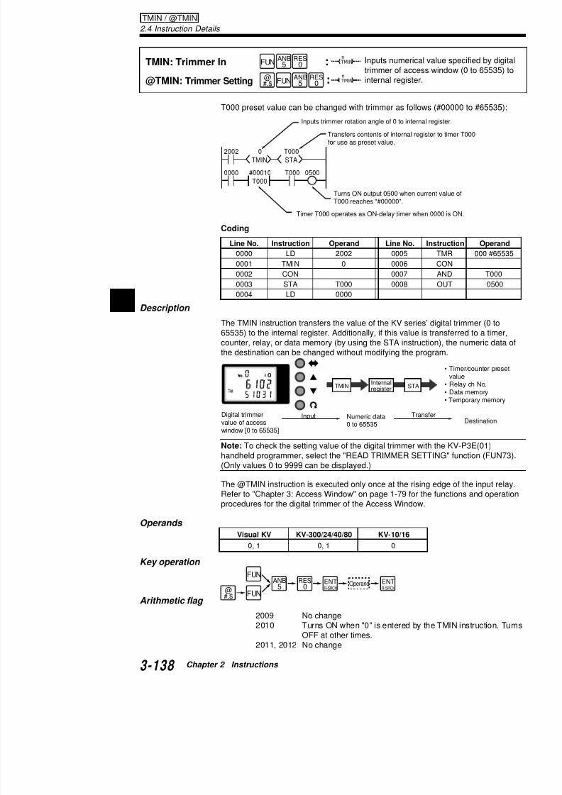
7/18/2019 Keyence Programming
http://slidepdf.com/reader/full/keyence-programming 162/392
2
Coding
Description
The TMIN instruction transfers the value of the KV series’ digital 65535) to the internal register. Additionally, if this value is transfecounter, relay, or data memory (by using the STA instruction), thethe destination can be changed without modifying the program.
Note: To check the setting value of the digital trimmer with the Khandheld programmer, select the "READ TRIMMER SETTING" f(Only values 0 to 9999 can be displayed.)
The @TMIN instruction is executed only once at the rising edge
pT000 reaches "#00000".
Timer T000 operates as ON-delay timer when 0000 is
Line No. Instruction Operand Line No. Instructi
0000 LD 2002 0005 TMR
0001 TMIN 0 0006 CON
0002 CON 0007 AND
0003 STA T000 0008 OUT
0004 LD 0000
STATMIN
Digital trimmervalue of accesswindow [0 to 65535]
Internalregister
TransferNumeric data0 to 65535
Input
• T
va• R• D• Te
Applications of TMIN (Analog timer) instruction
Changing the timer setting value
Uses the digital trimmer (TMIN0) to change the settingsec.).
Coding
Line No Instruction Operand Line No
0 TMIN
T000STA
2002
0000
0500 0500 T000
#00010 T000
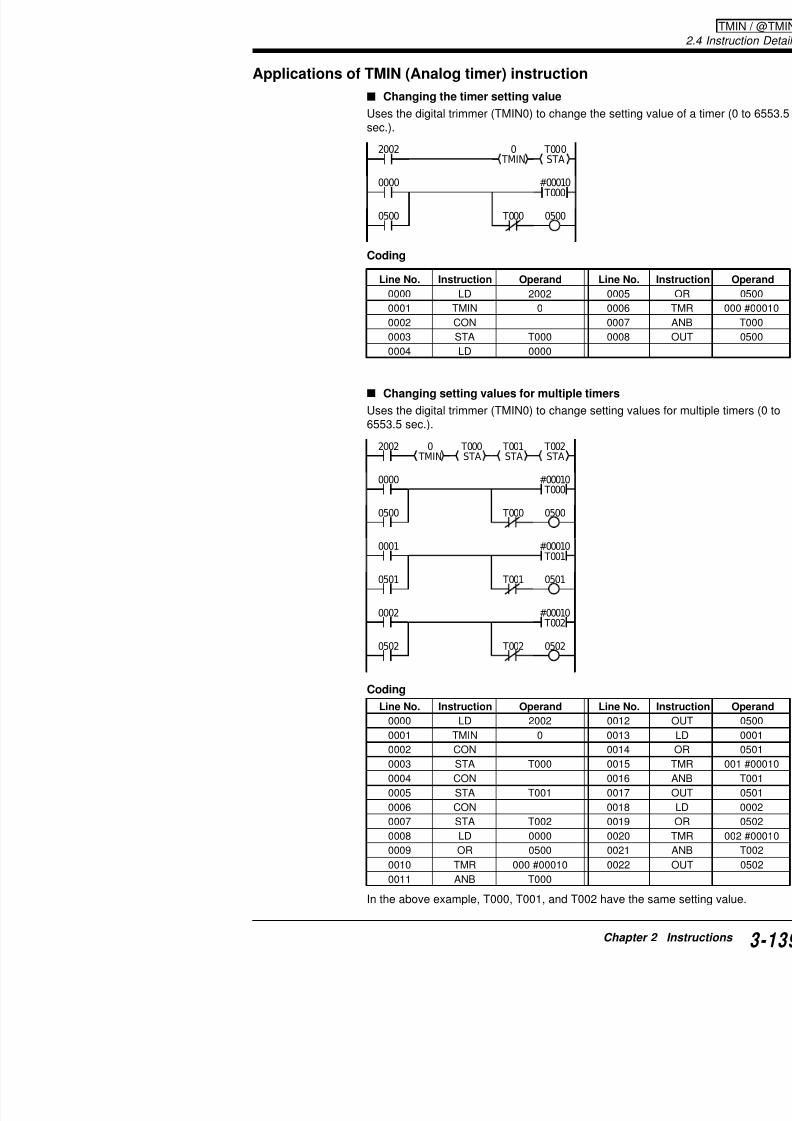
7/18/2019 Keyence Programming
http://slidepdf.com/reader/full/keyence-programming 163/392
Changing setting values for multiple timers
Uses the digital trimmer (TMIN0) to change setting va6553.5 sec.).
Line No. Instruction Operand Line No.
0000 LD 2002 0005
0001 TMIN 0 0006
0002 CON 0007
0003 STA T000 0008
0004 LD 0000
0 TMIN
T000STA
T001STA
T002STA
#00010 T000
2002
0000
0500 T000
#00010 T001
0001
0501 T001
0500
0501
#00010 T002
0002
0502 T0020502
2.4 Instruction Details
The LDA instruction inputs each data item to the internal registerThe STA instruction transfers the contents of the internal registerdestination.
LDA: Load A
@LDA: Load A
STA: Store A
@STA: Store A
Inputs value specified byregister.
Transfers contents of intedestination specified by o
@#,$
FUN
FUN
@
#,$
FUN
FUN
LDB4
ANL2
ORL3
ORL3
LDB
4
ANL2
ORL3
ORL
3
nnnnSTA
nnnnSTA
nnnnLDA
nnnnLDA
(#XXXXX)($XXXXX)
1 Constant Decimal
Hexadecimal
Storage Transfer Des
r
T/C presevalue
InputSource
LDA / @LDA / STA @STA
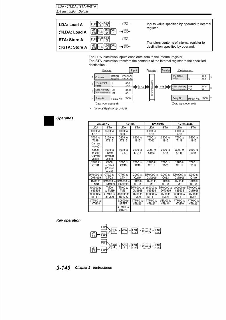
7/18/2019 Keyence Programming
http://slidepdf.com/reader/full/keyence-programming 164/392
2
"Internal Register" (p. 3-126)
Operands
T XXXC XXX
DM XXXXTM XX
XXXX
2
3
4
LDA STA
T/C currentvalue
Data memoryTemporary memory
Relay No. Relay No.
Internalregister
Data memTemporary m
Relay No
(Data type: operand) (Data typ
Visual KV KV-300 KV-10/16 KV-
LDA STA LDA STA LDA STA LDA
0000 to 0500 to 0000 to 0000 to 0000 t17915 1915 0009 2915 6915
T000 to 2100 to 0500 to 0500 to T000 to 0500 to T000 tT249 17915 17915 1915 T063 1915 T119
(Currentvalue)
C000 T000 to T000 to 2100 to C000 to 2100 to C000 t to 249 T249 T249 17915 C063 2915 C119(Current (Presetvalue) value)
CTH0 to C000 C000 to T000 to CTH0 to T000 to CTH0 t CTH1 to C249 C249 T249 CTH1 T063 CTH1
(Presetvalue)
DM0000 to CTC0 to CTH0 to C000 to DM0000 to C000 to DM0000 DM1999 CTC3 CTH1 C249 DM0999 C063 DM199
TM00 to DM0000 to DM0000 to CTC0 to TM00 to CTC0 to TM00 t TM31 DM1999 DM9999 CTC3 TM31 CTC3 TM31
#00000 to TM00 TM00 to DM0000 to #00000 to DM0000 to #00000#65535 to TM29 TM31 DM9999 #65535 DM0999 #6553
$0000 to #TM00 to #00000 to TM00 to $0000 to TM00 to $0000
Arithmetic flag
2009 No change2010 Turns ON when the contents of the
"LDA #00000" is executed. Turns O2011 No change2012 Turns ON when the DM or relay ind
out of range. "Indirect addressing" (p. 3-127)
Application of LDA and STA instructions
Changing the counter setting value
When 0000 is ON, #001preset value.
0000 #00100LDA
C001STAa)
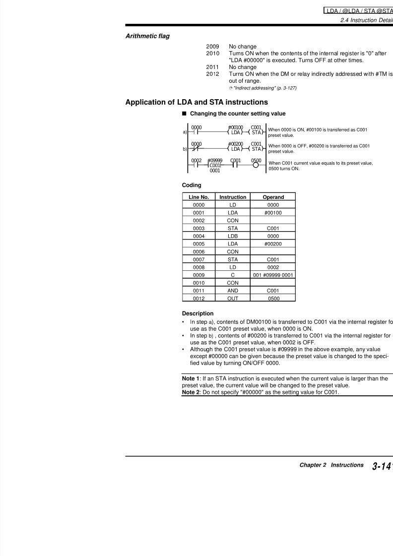
7/18/2019 Keyence Programming
http://slidepdf.com/reader/full/keyence-programming 165/392
Coding
Description
• In step a), contents of DM00100 is transferred to Cuse as the C001 preset value, when 0000 is ON.
• In step b) , contents of #00200 is transferred to C0
When 0000 is OFF, #00preset value.
When C001 current valu0500 turns ON.
C001 0500
b)0000
0002
#00200LDA
C001STA
#09999C0010001
Line No. Instruction Operand
0000 LD 0000
0001 LDA #00100
0002 CON
0003 STA C001
0004 LDB 0000
0005 LDA #00200
0006 CON
0007 STA C001
0008 LD 0002
0009 C 001 #09999 0001
0010 CON
0011 AND C001
0012 OUT 0500
2.4 Instruction Details
Transferring the current counter value to data memory (D
Coding
The C010 current value is transferred to D
0001
2002 C010LDA
DM0000STA
#09999C0100000
a)
Line No. Instruction Operand
0000 LDB 0001
0001 C 010 #099999 0000
0002 LD 2002
0003 LDA C010
0004 CON
0005 STA DM0000
LDA / @LDA / STA @STA
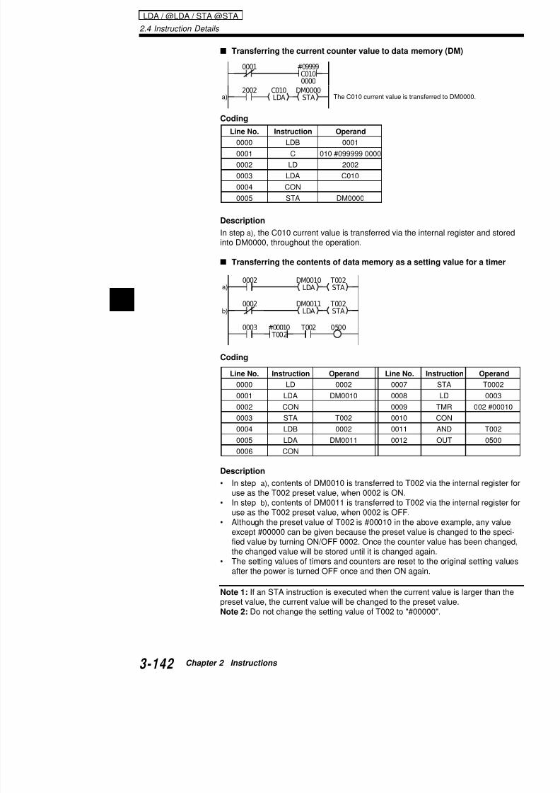
7/18/2019 Keyence Programming
http://slidepdf.com/reader/full/keyence-programming 166/392
2
Description
In step a), the C010 current value is transferred via the internal reinto DM0000, throughout the operation.
Transferring the contents of data memory as a setting va
Coding
Description
• In step a) contents of DM0010 is transferred to T002 via the
0005 S 0000
0002
T002 0500
b)
DM0010
LDA
T002
STA
0002
0003
DM0011LDA
T002STA
#00010 T002
a)
Line No. Instruction Operand Line No. Instruct0000 LD 0002 0007 STA
0001 LDA DM0010 0008 LD
0002 CON 0009 TMR
0003 STA T002 0010 CON
0004 LDB 0002 0011 AND
0005 LDA DM0011 0012 OUT
0006 CON
Outputting the input (ON/OFF status) of a basicsion output unit
The ON/OFF status of a KV series basic unit is outputnected next to the basic unit.
Coding
2002 0000LDA
0600STA
Line No. Instruction Operand
0000 LD 2002
0001 LDA 0000
0002 CON
0003 STA 0600
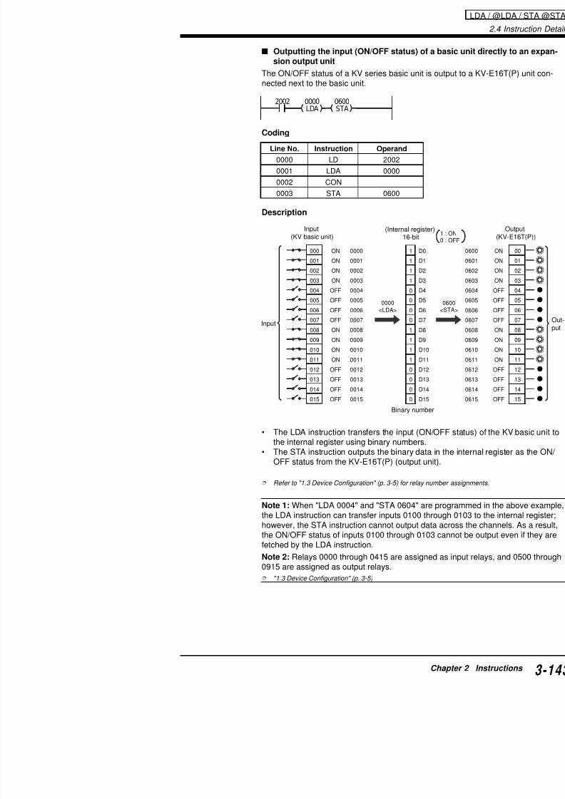
7/18/2019 Keyence Programming
http://slidepdf.com/reader/full/keyence-programming 167/392
Description
• The LDA instruction transfers the input (ON/OFF sthe internal register using binary numbers.
• The STA instruction outputs the binary data in the
OFF status from the KV-E16T(P) (output unit).
Refer to "1.3 Device Configuration" (p. 3-5) for relay number as
1 : ON0 : OF
D0
D1
D2
D3
D4D5
D6
D7
D8
D9
D10
D11
D12
D13
D14
D15
1
1
1
1
00
0
0
1
1
1
1
0
0
0
0
000
001
002
003
004005
006
007
008
009
010
011
012
013
014
015
0000
0001
0002
0003
00040005
0006
0007
0008
0009
0010
0011
0012
0013
0014
0015
ON
ON
ON
ON
OFFOFF
OFF
OFF
ON
ON
ON
ON
OFF
OFF
OFF
OFF
0600<STA>
0000<LDA>
Input (KV basic unit)
(Internal register) 16-bit
Binary number
Input
2.4 Instruction Details
When a BCD (2-digit) digital switch is connected to inputs0007 and a toggle switch is connected to inputs 0008 thro
a) Use the value of the digital switch (2 digits) as the setting valu(C001).
b) The current value of the counter (C001) is output to 0500 to 0output.
Coding
0008
0010 0000LDA
$00FFANDA TBIN
C001STA
#09999C0010009
0011 C001LDA TBCD
0500STAb)
a)
Line No. Instruction
0000 LDB
0001 C
0002 LD
0003 LDA
0004 CON
0005 ANDA
0006 CON
LDA / @LDA / STA @STA

7/18/2019 Keyence Programming
http://slidepdf.com/reader/full/keyence-programming 168/392
2 Description
<59>
D0
D1
D2
D3D4
D5
D6
D7
D8
D9
D10
D11
D12
D13
D14
1
1
0
11
1
0
0
0
0
0
0
0
0
0
<TBIN>
1
0
0
11
0
1
0
0
0
0
0
0
0
0
$00FF<ANDA>
1
0
0
11
0
1
0
0
1
1
1
0
0
0
ON
OFF
OFF
ONON
OFF
ON
OFF
OFF
ON
ON
ON
OFF
OFF
OFF
000
001
002
003004
005
006
007
008
009
010
011
012
013
014
07000<LDA>
Digital switch
Reset input
ProximitySW input
SW input
Internal register
ON/OFFstatus istrans-ferred tointernal
register.
Only low-order 2digits isused.
BCDdata isconvertedinto binarydata.
0007 TBIN
0008 CON
0009 STA
0010 LD
0011 LDA
0012 CON
0013 TBCD
0014 CON
0015 STA
Note 3: When an STA instruction is executed while tha timer is smaller than the current value, the current vsetting value.
First-in first-out (FIFO)
The data once fetched is written into DM0004,DM0003, …, to DM0000 in this order. At the
unloading timing, data is fetched fromDM0004 and the contents of DM are shiftedto the next DM.
The OK/NG judgment and unloading timings can be ugrams.

7/18/2019 Keyence Programming
http://slidepdf.com/reader/full/keyence-programming 169/392
Coding
0000 1000 0001
DM0004LDA
$1111LDA
DM0000STA
$0000CMP
DM0003LDA
DM0004STA
$0000LDA
DM0003STA
1000
0001 $5555LDA
DM0000STA
DIFU
2002 2010
DM0003LDA
$0000CMP
DM0002LDA
DM0003STA
$0000LDA
DM0002STA
2002 2010
DM0002LDA $0000CMP DM0001LDA DM0002STA $0000LDA DM0001STA2002 2010
DM0001LDA
$0000CMP
DM0000LDA
DM0001STA
$0000LDA
DM0000STA
2002
$0000 DM0004STA
0002
2010
LDA
ContentsWhen twprevious transferre
"$0000" is transferred to DMat unloading timing.
OK/NG judgmenttiming OK/NG judgment
"$1111" is transferred toDM0000.
"$5555" is transferred to DM0000.
Unloadingtiming
Line No. Instruction Operand
0000 LD 00000001 DIFU 1000
0002 CON
0003 AND 1000
0004 MPS
0005 AND 0001
0006 LDA $1111
0007 CON
0008 STA DM0000
0009 MPP
0010 ANB 0001
0011 LDA $55550012 CON
0013 STA DM0000
LD
Line No.
00350036
0037
0038
0039
0040
0041
0042
0043
0044
0045
00460047
0048
2.4 Instruction Details
CMP instruction compares the contents of the internal register w
fied by the operand, and turns ON/OFF the special utility relays (according to the result of comparison.
Comparing the current value of the counter and CMP value
CMP: Compare
@CMP: Compare
Compares contents of intvalue specified by operan@
#,$
FUN
FUN
LDB4
RES0
LDB4
RES0
nnnnCMP
nnnnCMP
2009 2010
(Internal register) < (Operand) ON OFF
(Internal register) = (Operand) OFF ON
(Internal register) > (Operand) OFF OFF
:
:
CMP / @CMP

7/18/2019 Keyence Programming
http://slidepdf.com/reader/full/keyence-programming 170/392
2
1) Output relay 0500 turns ON when the counter value is smalle< #01000).
2) Output relay 0501 turns ON when the counter value is equal t#01000).
3) Output relay 0502 turns ON when the counter value is greate> #01000).
4) Output relay 0503 turns ON when the counter value is equal t"2000" (C001 ≥ #02000).
Coding
0001
C001LDA
#01000CMP
0500
#09999
0003C001
2) (=)
1) (<)
3) (>)
4) (≥)
2002
C001LDA
#02000CMP
2002
2009
05012010
05022011
05032009
Line No. Instruction Operand Line No. Instruct
0000 LDB 0001 0012 OUT
0001 C 001 #099999 0003 0013 MPP0002 LD 2002 0014 AND
0003 LDA C001 0015 OUT
Operands
Key operation
Arithmetic flag
2009 T ON h h l f h CMP i
@#,$ FUN
FUNLDB
4RES
0 ENT
R-SRCHENTR-SRCH
Operand
Visual KV KV-300 KV-10/16
DM0000 to DM1999 DM0000 to DM9999 DM0000 to DM0TM00 to TM31 TM00 to TM31 TM00 to TM3
#00000 to #65535 #00000 to #65535 #00000 to #655$0000 to $FFFF $0000 to $FFFF $0000 to $FFF#TM00 to #TM29 #TM00 to #TM29 #TM00 to #TM
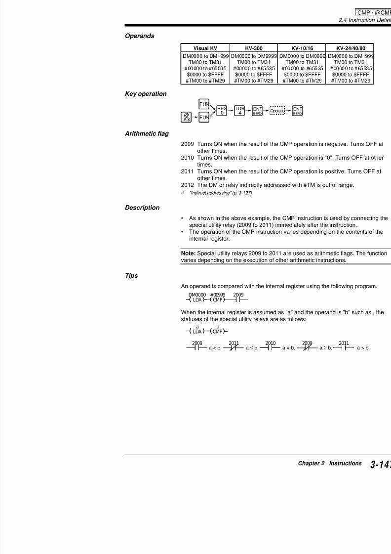
7/18/2019 Keyence Programming
http://slidepdf.com/reader/full/keyence-programming 171/392
2009 Turns ON when the result of the CMP operationother times.
2010 Turns ON when the result of the CMP operationtimes.
2011 Turns ON when the result of the CMP operationother times.
2012 The DM or relay indirectly addressed with #TM
"Indirect addressing" (p. 3-127)
Description
• As shown in the above example, the CMP instructspecial utility relay (2009 to 2011) immediately afte
• The operation of the CMP instruction varies depeninternal register.
Note: Special utility relays 2009 to 2011 are used as a
varies depending on the execution of other arithmetic
Tips
An operand is compared with the internal register usin
When the internal register is assumed as "a" and the ostatuses of the special utility relays are as follows:
#00999CMP
DM0000LDA
2009
aLDA CMP
b
2.4 Instruction Details
Application of CMP instruction
Multi-level counterCoding
0001
C000
LDA
#00999
CMP
#01999CMP
#02999CMP
0500
#09999
0000C000
2002 2011
05012011
05022011
0500
0500 0501
Line No. Instruc
0000 LDB
0001 C
0002 LD
0003 LDA
0004 CON
0005 MPS
0006 CMP
0007 CON
0008 ANB
0009 OUT
CMP / @CMP

7/18/2019 Keyence Programming
http://slidepdf.com/reader/full/keyence-programming 172/392
2
20092002 0500DM0000<#01000
DM0000LDA
#01000CMP
Description
The following outputs are provided according to the current value
(Current value) (Output)0000 to 0999 0500 turns ON.1000 to 1999 0501 turns ON.2000 to 2999 0502 turns ON.
When comparing values with no specific range
Turns ON 0500 when the DM0000 value is smaller than the CMPTurns ON 0501 when the DM0000 value is equal to the CMP valTurns ON 0502 when the DM0000 value is greater than the CMP
0009 OUT0010 MRD
0011 CMP
0012 CON
0013 ANB
0014 ANB
0015 OUT
0016 MPP
0017 CMP0018 CON
0019 ANB
0020 ANB
0021 ANB
0022 OUT
Setting the upper/lower limit
Turns ON 0500 when the C001 value is 1000 or less.Turns ON 0501 when the C001 value is 2000 or more
Coding
2011
2009
0001
2002
2002
C001≤#01000
C001≥#02000
C001
LDA
C001LDA
#01000
CMP
#02000CMP
0500
0501
#09999
0000C001
Line No. Instruction Operand Line No.
0000 LDB 0001 0008
0001 C 001 #09999 0000 0009

7/18/2019 Keyence Programming
http://slidepdf.com/reader/full/keyence-programming 173/392
Changing the CMP setting value
Compares the current value of counter C000 with the value of the CMP instruction is specified with the digitfollowing example changes the setting value to the ranThe upper limit of the digital trimmer is set to "100".
0500 turns ON when the current value of C000 is smavalue.0501 turns ON when the current value of C000 is equ
setting value.
0001 C 001 #09999 0000 00090002 LD 2002 0010
0003 LDA C001 0011
0004 CON 0012
0005 CMP #01000 0013
0006 CON 0014
0007 ANB 2011 0015
Sets range of
2009
2009
0001
2002
2002
C000LDA
DM0000CMP
DM0000STA
0 TMIN
0500
0501
#09999
00000C000
2.4 Instruction Details
ADD: Add
@ADD: Add
SUB: Subtract
@SUB: SubtractMUL: Multiply
@MUL: Multiply
DIV: Divide
@DIV: Divide
Adds value specified by operinternal register, and inputs reinternal register.
@#,$
FUN
FUN
@#,$
FUN
FUN
@#,$
FUN
FUN
@#,$
FUN
FUN
LDB4
SET1
SET1
RES0
RES0
AND8
ANL2
ORB6
LDB
4
SET1
SET1
RES0
RES0
AND8
ANL2
ORB
6
nnnnDIV
nnnnDIV
nnnnMUL
nnnnMUL
nnnn
SUB
nnnnSUB
nnnnADD
nnnnADD:
:
:
::
:
:
:
Subtracts value specified by ocontents of internal register, a
back to same register.
Multiplies contents of internalspecified by operand, and inpsame register.
Divides contents of internal respecified by operand, and inpsame register.
ADD / @ADD / SUB / @SUB / MUL / @MUL / DIV / @DIV
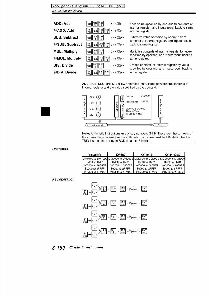
7/18/2019 Keyence Programming
http://slidepdf.com/reader/full/keyence-programming 174/392
2
ADD, SUB, MUL, and DIV allow arithmetic instructions between internal register and the value specified by the operand.
Note: Arithmetic instructions use binary numbers (BIN). Thereforthe internal register used for the arithmetic instruction must be BI
TBIN instruction to convert BCD data into BIN data.
Operands
Key operation
ADD
SUB
MUL
DIV
(#XXXXX)
($XXXX)
DM0000 to DM1999TM00 to TM31#TM00 to #TM29In
ternalregister
Op
erand
C o n s
t a n
t s
Datamemories
Hexadecimal
ResultArithmetic operation
Decimal
Interna
lregister
Visual KV KV-300 KV-10/16 KV
DM0000 to DM1999 DM0000 to DM9999 DM0000 to DM0999 DM000TM00 to TM31 TM00 to TM31 TM00 to TM31 TM0
#00000 to #65535 #00000 to #65535 #00000 to #65535 #0000$0000 to $FFFF $0000 to $FFFF $0000 to $FFFF $000
#TM00 to #TM29 #TM00 to #TM29 #TM00 to #TM29 #TM0
ADD (Addition)
Coding
Description
Th ADD i i dd h d l h
DM0000LDA
#00100ADD
DM0001STA
2002
Line No. Instruction Operand
0000 LD 2002
0001 LDA DM0000
0002 CON
0003 ADD #00100
0004 CON
0005 STA DM0001

7/18/2019 Keyence Programming
http://slidepdf.com/reader/full/keyence-programming 175/392
• The ADD instruction adds the operand value to theregister and inputs the result back to the internal re
• In the above example, "#00100" is added to the coresult is stored in DM0001.
• When the contents of DM0000 is "#00100", for exaDM0001.DM0000 (#00100) + #00100 → DM0001(#00200)
Note 1: An overflow occurs when the operation result#65535). In such a case, only the data of the low-ordeinternal register. For example, when the contents of thand the operand is "$0001", the result will overflow.
Note 2: When an overflow occurs, special utility relay
Tips
Solution when operation result overflows 16 bits
Example:Internal register 1
1
1 1 1 1 1 1 1 1 1 1 1 1
0+ 0 0 0 0 0 0 0 0 0 0 0 0
0
2009
0 0 0 0 0 0 0 0 0 0 0 0
Operand
Overflow
Specialutility relay
Input back internal register
DM0000 DM0001 DM0002 #00000 DM00032002 2009
2.4 Instruction Details
Application of ADD instruction
Total count
Writes the total count of counters C001 to C003 into DM0100. Thbe within #65535.
C di
Writes C001 current value intoC001LDA
DM0001STA
0000
C002LDA
DM0002STA
0000
C003LDA
DM0003STA
0000
DM0002ADD
DM0001LDA
DM0003ADD
DM0100STA
2002
#09999C003
#09999C001
0001
0002
#09999C002
0003
Writes C002 current value int
Writes C003 current value int
Writes total count (DM0001 +DM0003) into DM100.
ADD / @ADD

7/18/2019 Keyence Programming
http://slidepdf.com/reader/full/keyence-programming 176/392
2
Coding
Line No. Instruction Operand
0000 LDB 0001
0001 C 010 #099999 0000
0002 CON
0003 LDA C001
0004 CON0005 STA DM0001
0006 LDB 0000
0007 C 002 #099999 0002
0008 CON
0009 LDA C002
0010 CON
0011 STA DM0002
0012 LDB 00000013 C 003 #099999 0003
0014 CON
0015 LDA C003
0016 CON
0017 STA DM0003
0018 LD 2002
0019 LDA DM0001
0020 CON
0021 ADD DM0002
SUB (Subtraction)
Coding
Description
• The SUB instruction subtracts the operand value f
DM0000LDA
#00100SUB
DM0001STA
2002
Line No. Instruction Operand
0000 LD 2002
0001 LDA DM0000
0002 CON
0003 SUB #00100
0004 CON
0005 STA DM0001
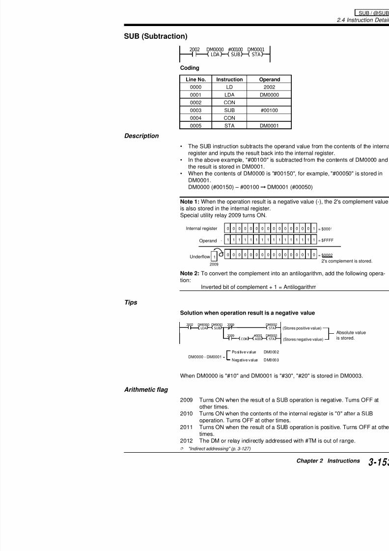
7/18/2019 Keyence Programming
http://slidepdf.com/reader/full/keyence-programming 177/392
pregister and inputs the result back into the internal
• In the above example, "#00100" is subtracted fromthe result is stored in DM0001.
• When the contents of DM0000 is "#00150", for exaDM0001.DM0000 (#00150) – #00100 DM0001 (#00050)
Note 1: When the operation result is a negative valueis also stored in the internal register.Special utility relay 2009 turns ON.
Note 2: To convert the complement into an antilogarittion:
Inverted bit of complement + 1 = Antilogarithm
Tips
Solution when operation result is a negative value
0
1
0 0 0 0 0 0 0 0 0 0 0 0 0 0
1- 1 1 1 1 1 1 1 1 1 1 1 1 1 1
0 0 0 0 0 0 0 0 0 0 0 0 0 0 1 0
2009
Internal register
Operand
Underflow
DM0000LDA
DM0001SUB
DM0002STA
#0001 DM0003
2002 2009
2009
(Stores positive va
2.4 Instruction Details
Application of SUB instruction
Comparing absolute values
Compares the DM0000 value to the DM0001 value and turns ONdifference between the two absolute values is greater than 5.
Coding
2002 20092009DM0000LDA
DM0001SUB
#0005CMP
1001
1000
2009 DM0001LDA
DM0000SUB
1000
2009#00005CMP
1001
0500
Line No. Instruction Operand
SUB / @SUB

7/18/2019 Keyence Programming
http://slidepdf.com/reader/full/keyence-programming 178/392
2
0000 LD 2002
0001 LDA DM0000
0002 CON
0003 SUB DM0001
0004 MPS
0005 ANB 2009
0006 CMP #00005
0007 CON
0008 ANB 2009
0009 OUT 1000
0010 MPP
0011 AND 2009
0012 LDA DM0001
0013 CON
0014 SUB DM00000015 CON
0016 CMP #00005
0017 CON
0018 ANB 2009
0019 OUT 1001
0020 LD 1000
0021 OR 1001
0022 OUT 0500
MUL (Multiplication)
Coding
Description
• The MUL instruction multiplies the contents of the
DM0000LDA
#00100MUL
DM0001STA
2002
Line No. Instruction Operand
0000 LD 2002
0001 LDA DM0000
0002 CON
0003 MUL #00100
0004 CON
0005 STA DM0001

7/18/2019 Keyence Programming
http://slidepdf.com/reader/full/keyence-programming 179/392
and value and inputs the result back to the internal• In the above example, the contents of DM0000 are
the result is stored in DM0001.• When the contents of DM0000 is "#00200", for exa
DM0001.DM0000 (#00200) x #00100→DM0001 (#20000)
Note 1: An overflow occurs when the operation resultsuch a case, only the data of the low-order 16 bits areand the overflow data of the high-order 16 bits is storehigh-order 16 bits is always stored in TM00.)
Note 2: When an overflow occurs, special utility relay
Tips
Solution when operation result overflows 16 bits
DM0000 x DM0001 DM0003 (High order 16 bits) D
F
(TM00)
F F F
0 0 0 2
F F F F0 0 0 1
(Internal register)
Internal register
Operand Hexadecimal number
2002 DM0000LDA
DM0001MUL
DM0002STA
TM00LDA
DM0003STA
2.4 Instruction Details
Application of MUL instruction
Multiplying the counter current value by the DM value
Multiplies the counter current value by the DM0000 value and wr16 bits of the product into DM0101 and low-order 16 bits of the pDM0100.
Coding
0001
C001LDA
DM0000MUL
DM0100STA
TM00LDA
DM0101STA
2002
#09999
0000C001
Line No. Instruction Operand
0000 LDB 0001
0001 C 001 #099999 00000002 LD 2002
MUL / @MUL / DIV / @DIV

7/18/2019 Keyence Programming
http://slidepdf.com/reader/full/keyence-programming 180/392
2
2002 DM0001LDA
TM00STA
DM0000LDA
#00100DIV
DM0002STA
TM00LDA
DM000STA
Line No. Instruction Operand
0000 LD 2002
0001 LDA DM0001
0002 CON
0003 STA TM00
0004 CON
DIV (Division)
Coding
0002 LD 2002
0003 LDA C001
0004 CON
0005 MUL DM0000
0006 CON
0007 STA DM0100
0008 CON
0009 LDA TM00
0010 CON
0011 STA DM0101
High-order Low-order Low-order High-ord
Arithmetic flag
2009 No change2010 Turns ON when all 32 bits are "0" after a DIV o
times.2011 No change2012 Turns ON when the divisor of a DIV operation
indirectly addressed with #TM is out of range.
"Indirect addressing" (p. 3-127)
Description
• The 32-bit value (binary) consisting of the higher 1bits from the internal register is divided by the valuThe higher 16 bits of the result is input back to TMsame internal register. The remainder is stored in T
TM00 Internal register Operand
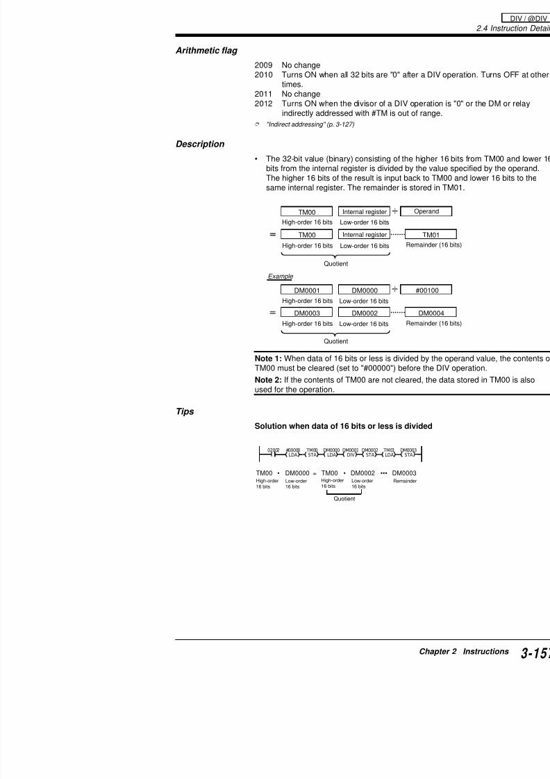
7/18/2019 Keyence Programming
http://slidepdf.com/reader/full/keyence-programming 181/392
Note 1: When data of 16 bits or less is divided by the
TM00 must be cleared (set to "#00000") before the DINote 2: If the contents of TM00 are not cleared, the dused for the operation.
Tips
Solution when data of 16 bits or less is divided
TM00 TM01
DM0000DM0001
DM0002DM0003 DM0004
#00100
Quotient
Example
Low-order 16 bits
Remainder (1
High-order 16 bits
Internal register
Remainder (1Low-order 16 bitsHigh-order 16 bits
Low-order 16 bitsHigh-order 16 bits
Low-order 16 bitsHigh-order 16 bits
Quotient
02002 #00000
LDA
TM00
STA
DM0000
LDA
DM0001
DIV
DM0002
STA
TM01
LDA
DM0003
STA
TM00 • DM0000 = TM00 • DM0002 ••• DM0003
2.4 Instruction Details
Application of DIV instruction
Total count average
Outputs the average of 3 counter values in 4-digit BCD.(C001 + C002 + C003) ÷ 3 BCD output valueThe BCD value is output to 500 to 515.
C001LDA DM0001STA0000
C002LDA
DM0002STA
0000
C003LDA
DM0003STA
0000
DM0001LDA
DM0002ADD
DM0003ADD
2002
#09999C0030003
#09999C001
#09999
0001
0002C002
(DM0001+DM0002+DM0003)
TM00STA
#00000LDA
2002
Writes the C001 current value into
Writes the C002 current value into
Writes the C003 current value into
DIV / @DIV
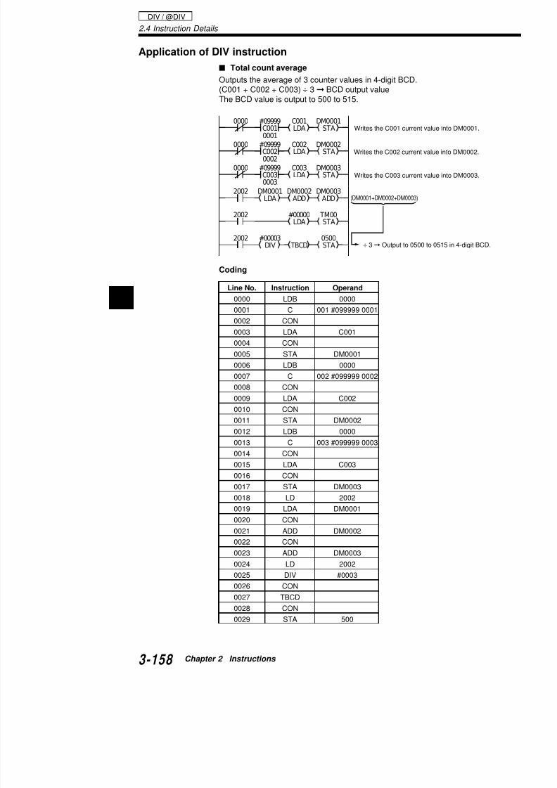
7/18/2019 Keyence Programming
http://slidepdf.com/reader/full/keyence-programming 182/392
2
Coding
STALDA
#00003DIV TBCD
0500STA
2002÷ 3 Output to 0500 to 0515
Line No. Instruction Operand
0000 LDB 0000
0001 C 001 #099999 0001
0002 CON
0003 LDA C001
0004 CON
0005 STA DM0001
0006 LDB 0000
0007 C 002 #099999 00020008 CON
0009 LDA C002
0010 CON
0011 STA DM0002
0012 LDB 0000
0013 C 003 #099999 0003
0014 CON
0015 LDA C003
0016 CON
Example
Coding
ANDA:
@ANDA:
ANDs convalue spec16 bits, anregister.
AND A
(Logical product) @#,$
FUN
FUNSET
1RES
0
SET1
RES0
nnnnANDA
nnnnANDA
Line No. Instruction Operand
0000 LD 0000
0001 LDA DM0000
0002 CON
0003 ANDA $00FF
0000 DM0000
LDA
$00FF
ANDA
DM0001
STA
(DM0000) ^ ($00FF) = (DM0001)
Logical product
:
:
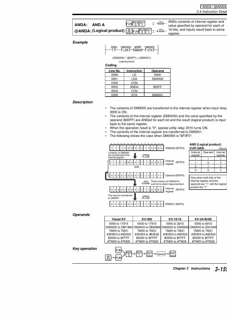
7/18/2019 Keyence Programming
http://slidepdf.com/reader/full/keyence-programming 183/392
Description
• The contents of DM0000 are transferred to the inte0000 is ON.
• The contents of the internal register (DM0000) and
operand ($00FF) are ANDed for each bit and the rback to the same register.
• When the operation result is "0", special utility rela• The contents of the internal register are transferred• The following shows the case when DM0000 is "$F
0004 CON
0005 STA DM0001
Contents of DM0000are transferred to theinternal register.
1
AND
1 1 1 0 0 0 0 1 1 1 1 0 0 0 0
1 1 1 1 0 0 0 0 1 1 1 1 0 0 0 0
0 0 0 0 0 0 0 0 1 1 1 1 1 1 1 1
0 0 0 0 0 0 0 0 1 1 1 1 0 0 0 0
DM0000LDA
$00FFANDA
DM0001
D15 D14 D13 D12 D11 D10 D9 D8 D7 D6 D5 D4 D3 D2 D1 D0
These values are ANDed foreach bit to obtain logical produc
The result is transferred
Internalregister
Operand ($F0F0
Internalregister
DM0000 ($F0F0
($F0F0
($F0F0
2.4 Instruction Details
Arithmetic flag
2009 No change2010 Turns ON when the internal register is "0" after an ANDA
Turns OFF at other times.2011 No change2012 The DM or relay indirectly addressed with #TM is out of r
"Indirect addressing" (p. 3-127)
Tips
Solution when connecting one-digit data of a BCD digital swto 0103, while ignoring other inputsOnly one-digit data of the BCD digital switch is transferred as thefetching counter (C004).Other inputs (0104 to 0115) are ignored.
0004
2002
#00300C0040005
0100LDA
$000FANDA TBIN
C004STA
ANDA / @ANDA

7/18/2019 Keyence Programming
http://slidepdf.com/reader/full/keyence-programming 184/392
2
Application of ANDA instruction
Fetch input data separately
Sets the low-order 2 digits of the BCD digital switch (7000 to 700and the high-order 2 digits (7008 to 7015) to timer T001.
Coding
LDA ANDA TBIN STA
7000LDA
$00FFANDA TBIN
C000STA
2002
TBIN#08SRA
$FF00ANDA
7000LDA
T001STA
2002
0001
0001
#09999C0000000
#09999
T001
Line No. Instruction Operand
0000 LD 2002
0001 LDA 7000
0002 CON
0003 ANDA $00FF
0004 CON
0005 TBIN
C
Converts data of 7000 twrites it into C000.
Shifts data to right by 8 and writes it into T001.
Sets C000.
Sets T001.
Example
Coding
Line No. Instruction Operand
0000 LD 0000
0001 LDA DM0000
0002 CON
0003 ORA $00FF
0004 CON
0005 STA DM0001
ORA:
@ORA:
ORs contentspecified by and inputs re
Or A
(Logical sum) @#,$
FUN
FUNSET
1ORL
3
SET1
ORL3
nnnnORA
nnnnORA
0000 DM0000LDA
$00FFORA
DM0001STA
(DM0000) U ($00FF) = (DM0001)
Logical sum
:
:

7/18/2019 Keyence Programming
http://slidepdf.com/reader/full/keyence-programming 185/392
Description
• The contents of DM0000 are transferred to the inte0000 is ON.
• The contents of the internal register (DM0000) andoperand ($00FF) are ORed for each bit and the res
to the same register.• When the operation result is "0", special utility rela• The contents of the internal register are transferred• The following shows the case when DM0000 is "$F
0005 STA DM0001
1
OR
1 1 1 0 0 0 0 1 1 1 1 0 0 0 0
1 1 1 1 0 0 0 0 1 1 1 1 0 0 0 0
0 0 0 0 0 0 0 0 1 1 1 1 1 1 1 1
1 1 1 1 0 0 0 0 1 1 1 1 1 1 1 1
1 1 1 1 0 0 0 0 1 1 1 1 1 1 1 1
DM0000LDA
$00FFORA
DM0001STA
D15 D14 D13 D12 D11 D10 D9 D8 D7 D6 D5 D4 D3 D2 D1 D0
Contents of DM0000 aretransferred to the internalregister.
These values are ORed foreach bit to obtain logical sum.
The result is transferredto DM0001.
Internalregister
Operand ($00FF)
Internalregister
DM000 ($F0F0)
($F0F0)
($F0FF)
2.4 Instruction Details
#00300
C0040005
0004
ORA / @ORA
Arithmetic flag
2009 No change2010 Turns ON when the internal register is "0" after an ORA o
OFF at other times.2011 No change2012 The DM or relay indirectly addressed with #TM is out of r
"Indirect addressing" (p. 3-127)
Tips
Solution when connecting two-digit data of a BCD digital swto 0103 for the first digit and 0200 to 0203 for the second digFetches the two-digit data of the BCD digital switch, which are sefirst digit (0100 to 0103) and the second digit (0200 to 0203), andvalues as the setting value of a counter (C004).
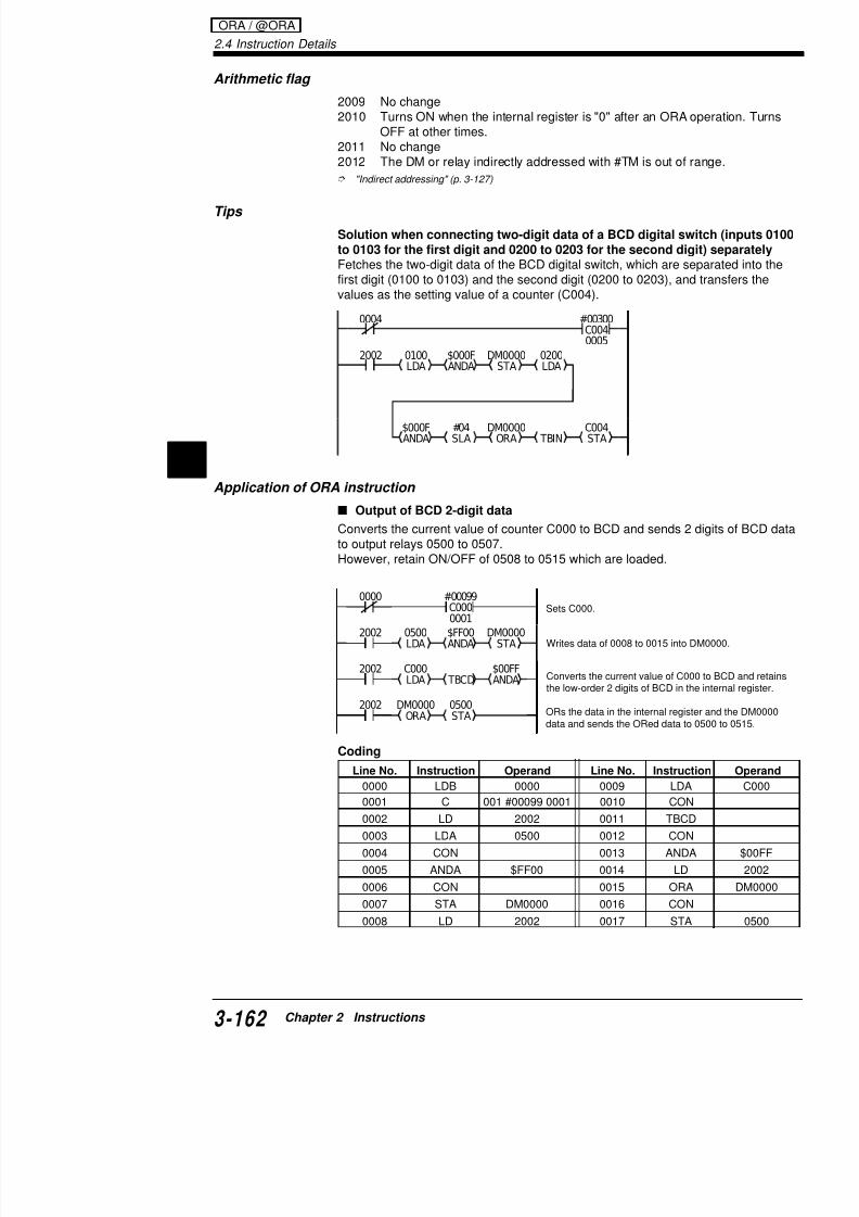
7/18/2019 Keyence Programming
http://slidepdf.com/reader/full/keyence-programming 186/392
2
0000
TBCDC000LDA
0500
STA
DM0000
ORA
$00FFANDA
$FF00ANDA
0500LDA
DM0000STA
2002
2002
2002
#00099C0000001
Sets C000.
Writes data of 0008 to 0015 into D
ORs the data in the internal registdata and sends the ORed data to
2002 0100LDA
$000FANDA
DM0000STA
0200LDA
$000FANDA
#04SLA
DM0000ORA
C004STA TBIN
Converts the current value of C00the low-order 2 digits of BCD in th
Application of ORA instruction
Output of BCD 2-digit data
Converts the current value of counter C000 to BCD and sends 2 to output relays 0500 to 0507.However, retain ON/OFF of 0508 to 0515 which are loaded.
0000
ANDA0100LDA
DM0000ORA TBIN
C001STA
#04SLA
$000F
$000F
ANDA0000LDA
DM0000STA
2002
2002
2002
#00099C0000001
Line No. Instruction Operand
0000 LDB 0001
Sets C00
Writes da
Writes dater.
Separate input of 2-digit BCD
Fetches only 2 digits of the BCD digital switch (0000 tto 0103 for the 2nd digit) and sets it as the counter va
Coding
ORs contto left by converts C001.
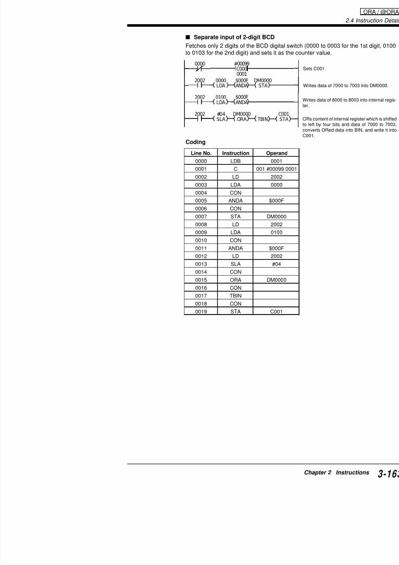
7/18/2019 Keyence Programming
http://slidepdf.com/reader/full/keyence-programming 187/392
0000 LDB 0001
0001 C 001 #00099 0001
0002 LD 2002
0003 LDA 0000
0004 CON
0005 ANDA $000F
0006 CON0007 STA DM0000
0008 LD 2002
0009 LDA 0100
0010 CON
0011 ANDA $000F
0012 LD 2002
0013 SLA #04
0014 CON
0015 ORA DM0000
0016 CON
0017 TBIN
0018 CON
0019 STA C001
2.4 Instruction Details
Example
Coding
EORA:
@EORA:
EXCLUSIVE ORs conregister and operand and inputs result back
Exclusive Or A
(Exclusivelogical sum)
@#,$
FUN
FUN SET
1ANB
5
SET1
ANB5
nnnnEORA
nnnnEORA
0000 DM0000LDA
$00FFEORA
DM0001STA
(DM0000) ($00FF) = (DM0001)U
Exclusivelogical sum
Line No. Instruction Operand
0000 LD 0000
0001 LDA DM0000
0002 CON
0003 EORA $00FF
0004 CON
:
:
EORA / @EORA
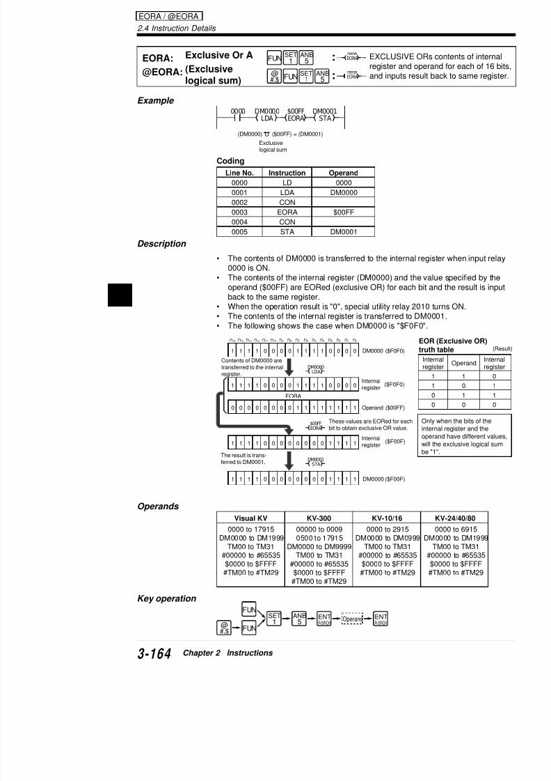
7/18/2019 Keyence Programming
http://slidepdf.com/reader/full/keyence-programming 188/392
2
Description
• The contents of DM0000 is transferred to the internal register0000 is ON.
• The contents of the internal register (DM0000) and the value
operand ($00FF) are EORed (exclusive OR) for each bit and back to the same register.• When the operation result is "0", special utility relay 2010 turn• The contents of the internal register is transferred to DM0001• The following shows the case when DM0000 is "$F0F0".
0004 CON
0005 STA DM0001
1
EORA
1 1 1 0 0 0 0 1 1 1 1 0 0 0 0
1 1 1 1 0 0 0 0 1 1 1 1 0 0 0 0
0 0 0 0 0 0 0 0 1 1 1 1 1 1 1 1
1 1 1 1 0 0 0 0 0 0 0 0 1 1 1 1
DM0000LDA
$00FFEORA
DM0001STA
D15 D14 D13 D12 D11 D10 D9 D8 D7 D6 D5 D4 D3 D2 D1 D0
Contents of DM0000 aretransferred to the internal
register.
Only whinternal operandwill the ebe "1".
These values are EORed for eachbit to obtain exclusive OR value.
The result is trans-ferred to DM0001.
Internalregister
Operand ($00FF)
Internalregister
EOR (Extruth tab
Internalregister
1
1
0
0
DM0000 ($F0F0)
($F0F0)
($F00F)
$
Arithmetic flag
2009 No change2010 Turns ON when the internal register is "0" after
OFF at other times.2011 No change2012 The DM or relay indirectly addressed with #TM
"Indirect addressing" (p. 3-127)
Tips
Turning output 0500 ON when inputs 0000 through 00constant ($0F0F)
When the values match, special internal relay 2010 tuturns ON.In this example, the constant is "$0F0F", or "0000 111
output relay 0500 turns ON when input relays 0000 th0011 are ON.
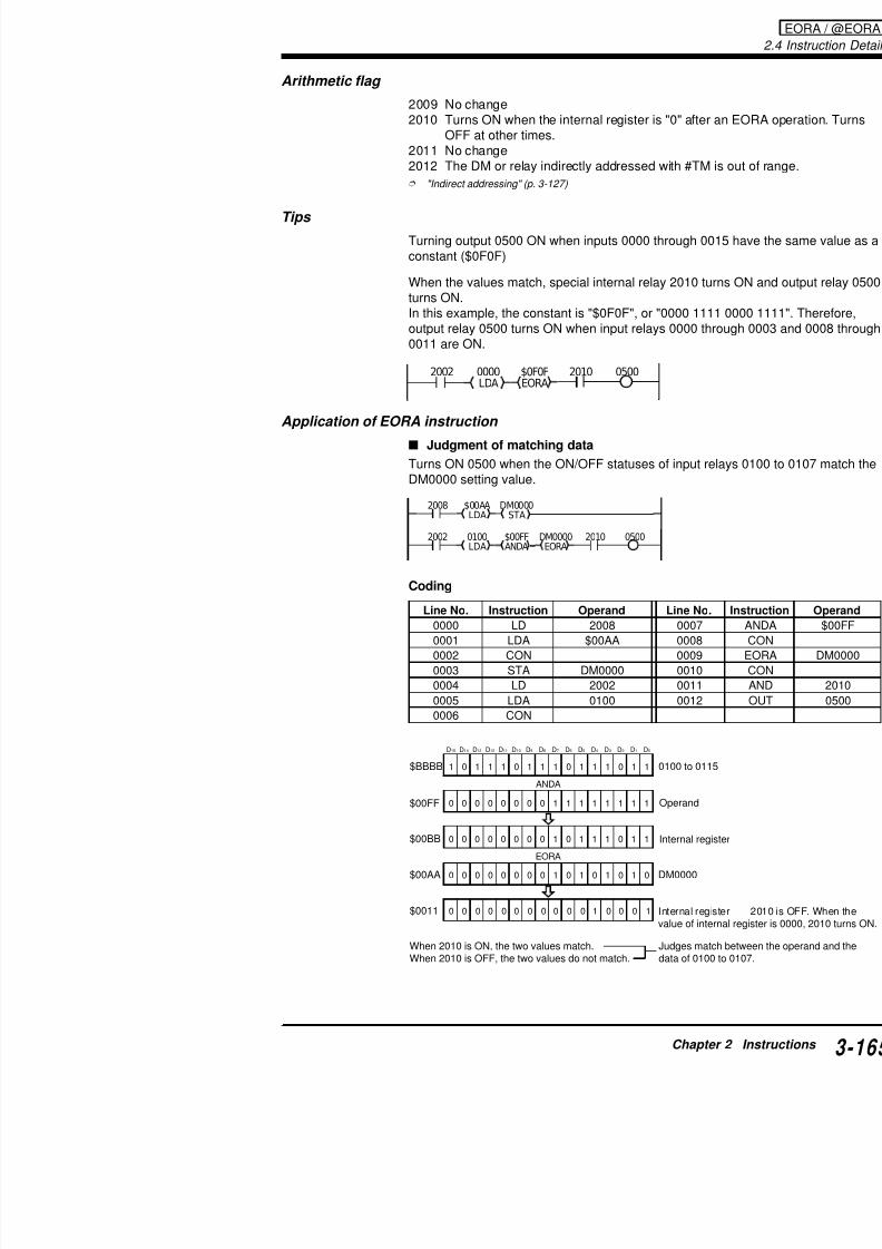
7/18/2019 Keyence Programming
http://slidepdf.com/reader/full/keyence-programming 189/392
Application of EORA instruction
Judgment of matching data
Turns ON 0500 when the ON/OFF statuses of input reDM0000 setting value.
Coding
2002 2010 0500$0F0FEORA
0000LDA
STA$00AA DM0000LDA
$00FFANDA
0100LDA
DM0000EORA
2008
2002 2010 0500
$BBBB
D15 D14 D13 D12 D11 D10 D9 D8 D7 D6 D5 D4 D3 D2 D1 D0
Line No. Instruction Operand Line No.
0000 LD 2008 0007
0001 LDA $00AA 0008
0002 CON 0009
0003 STA DM0000 0010
0004 LD 2002 0011
0005 LDA 0100 0012
0006 CON
2.4 Instruction Details
Example
Coding
SRA: Shift Right A
@SRA: Shift Right A
SLA: Shift Left A
@SLA: Shift Left A
Moves contents of inteserially right by value and.
Moves contents of inteserially left by value s
@#,$
FUN
FUN
@#,$
FUN
FUN
LDB4
LDB4
SET1
RES0
LDB4
LDB4
SET1
RES0
#ddSRA
#ddSRA
#ddSLA
#ddSLA
0000 DM0000LDA
#05SRA
DM0001STA
0001 DM0010LDA
#10SLA
DM0011STA
Line No. Instruction Operand
:
:
:
:
SRA / @SRA / SLA / @SLA

7/18/2019 Keyence Programming
http://slidepdf.com/reader/full/keyence-programming 190/392
2
Operands #01 to #16
Key operation
0000 LD 0000
0001 LDA DM0000
0002 CON
0003 SRA #05
0004 CON
0005 STA DM0001
0006 LD 0001
0007 LDA DM0010
0008 CON
0009 SLA #10
0010 CON
0011 STA DM0011
@# $ FUN
FUN
@#,$ FUN
FUNLDB
4
LDB4
SET1
RES0
ENTR-SRCH
ENTR-SRCH
Operand
ENTR-SRCH
ENTR-SRCH
Operand
Description
• Operations using the SRA instruction
When input relay 0000 is ON, the contents of DM0000register and shifted serially right by the operand valuewritten into DM0001. The contents of D0 are shifted toIn the above example, the contents shift to the right byscan time while input relay 0000 is ON.
Use @SRA, a differentiation type instruction, to execuwhen input relay 0000 turns ON.
• Operation using the SLA instruction
Carry
1 1 0 0 1 0 0 0 1 1 1 0 0 1 0 00
2009
0 0 0 0 0 1 1 0 0 1 0 0 0 1 1 1 0
2009
D15 D14 D13 D12 D11 D10 D9 D8 D7 D6 D5 D4 D3 D2 D1 D0
D15 D14 D13 D12 D11 D10 D9 D8 D7 D6 D5 D4 D3 D2 D1 D0
Carry

7/18/2019 Keyence Programming
http://slidepdf.com/reader/full/keyence-programming 191/392
p g
When input relay 0001 is ON, the contents of DM0000register and shifted serially left by the operand value (written into DM0011. The contents of D15 are shifted toIn the above example, the contents shift to the left by scan time while input relay 0001 is ON.Use @SLA, a differentiation type instruction, to execu
when input relay 0001 turns ON.
Note: Special utility relay 2009 may turn ON in accordresults; however, it changes immediately when anothe
1 1 0 0 1 0 0 0 1 1 1 0 0 1 0 00
2009
1 0 0 1 0 0 0 0 0 0 0 0 0 0 0 01
2009
D15 D14 D13 D12 D11 D10 D9 D8 D7 D6 D5 D4 D3 D2 D1 D0
D15 D14 D13 D12 D11 D10 D9 D8 D7 D6 D5 D4 D3 D2 D1 D0
Carry
Carry
2.4 Instruction Details
Application of SRA/SLA instructions
Fetching four-digit data of the BCD digital switch (inputs for low-order 2 digits and 0100 through 0107 for high-ordetransfer them as a counter setting value
Separate input of BCD
Fetches only 2 digits of the BCD digital switch (0112 to 0115 for t0003 for the 2nd digit) and sets it as the counter value.
2002 0000LDA
$0FF0ANDA
#04SRA
DM0000STA
0100LDA
$00FFANDA
#08SLA
DM0000ORA
C004STA
0001 #09999
C0040000
0001 #00099
SRA / @SRA / SLA / @SLA

7/18/2019 Keyence Programming
http://slidepdf.com/reader/full/keyence-programming 192/392
2
Coding
Line No. Instruction Operand
0000 LD 0001
0001 C 001 #00099 0000
0002 LD 2002
0003 LDA 0100
0004 CON
0005 ANDA $F0000006 LD 2002
0007 SRA #12
0001
STA#12SRA
$000FANDA
0000LDA
$F000
DM0000
ANDA0100LDA
2002
2002
2002
#00099C0010000
DM0000ORA
#04SLA
2002
C001STA TBIN
2002Converts the data of internal register to BIN C001.
Sets C001.
Sends the data of 0112 to 0115 to internal re
Shifts the value of internal register to right by
into DM0000.
Sends the data of 0000 to 0003 to internal re
Shifts the data of internal register to left by 4register data and the data of DM0000, and sthe internal register.
Example
Coding
RRA: Rotate Right A
@RRA: Rotate Right A
RLA: Rotate Left A
@RLA: Rotate Left A
Rotates concarry (2009)
Rotates concarry (2009)value.
@#,$
FUN
FUN
@
#,$
FUN
FUN
LD7
ANB5
ORL3
ORL3
LD7
ANB
5
ORL3
ORL
3
#ddRRA
#ddRRA
#ddRLA
#ddRLA
0000 DM0000LDA
#01RRA
DM0001STA
0001 DM0010LDA
#04RLA
DM0011STA
Line No. Instruction Operand
:
:
:
:

7/18/2019 Keyence Programming
http://slidepdf.com/reader/full/keyence-programming 193/392
Operands
#01 to #16
Key operation
p
0000 LD 0000
0001 LDA DM0000
0002 CON
0003 RRA #01
0004 CON
0005 STA DM0001
0006 LD 0001
0007 LDA DM0010
0008 CON
0009 RLA #04
0010 CON
0011 STA DM0011
@#,$ FUN
FUN
@#,$ FUN
FUNLD7
ANB5
ORL3
ORL3
ENTR-SRCH
ENTR-SRCH
Operand
ENTR-SRCH
ENTR-SRCH Operand
2.4 Instruction Details
Use @RRA, a differentiation type instruction, to execute the instrwhen input relay 0000 turns ON.
• Operation using the RLA instruction
When input relay 0001 is ON, the contents of DM0000 are transfregister. The contents of the internal register and carry (2009) areclockwise by the operand value.In the example above, the contents are rotated counterclockwisewhile input relay 0001 is ON.
Use @RLA, a differentiation type instruction, to execute the instrwhen input relay 0001 turns ON.
1 1 0 0 1 0 0 0 1 1 1 0 0 1 0 00
2009
0 1 1 0 0 1 0 0 0 1 1 1 0 0 1 002009
D15 D14 D13 D12 D11 D10 D9 D8 D7 D6 D5 D4 D3 D2 D1 D0
D15 D14 D13 D12 D11 D10 D9 D8 D7 D6 D5 D4 D3 D2 D1 D0
Carry
Carry
SRA / @SRA / SLA / @SLA

7/18/2019 Keyence Programming
http://slidepdf.com/reader/full/keyence-programming 194/392
2
#01RRA
2002
2002 2009 TM10INC
0000LDA
NEXT
FOR#00016
Writes the data of 0000 to 0015 int
Executes FOR-NEXT instruction 16
Shifts the data including carry (200
increments TM10 by 1 when 2009
Note: Special utility relay 2009 may turn ON in accordance with tresults; however, it changes immediately when another operation
Application of RRA/RLA instructions
Error input count
Writes the number of error detection sensors, which are connecte(0000 to 0015) and turn ON, into DM0000.
1 1 0 0 1 0 0 0 1 1 1 0 0 1 0 0 0
2009
1 0 0 0 1 1 1 0 0 1 0 0 0 1 1 0 0
2009
D15 D14 D13 D12 D11 D10 D9 D8 D7 D6 D5 D4 D3 D2 D1 D0
D15 D14 D13 D12 D11 D10 D9 D8 D7 D6 D5 D4 D3 D2 D1 D0
Carry
Carry
Example
Coding
COM:
@COM:Inverts contenregister.@
#,$
FUN
FUN
RES0
ANB5
RES0
ANB5
COM
COM
Complement
(Bit inversion)
0000
COM
DM0001
STA
DM0000
LDA
Line No. Instruction Operand
0000 LD 0000
0001 @LDA DM0000
0002 CON
0003 @COM
0004 CON0005 @STA DM0001
:
:

7/18/2019 Keyence Programming
http://slidepdf.com/reader/full/keyence-programming 195/392
Description
• Each time input relay 0000 turns from OFF to ON, transferred to the internal register. The COM instrubit and transfers the result to DM0001.
• Special utility relay 2010 turns ON when the result
• The following shows the case when DM0000 is "$5
Note:
When an every-scan type COM instruction is used, thevery scan time while input relay 0000 is ON.
Use @COM, a differentiation type instruction, to execwhen input relay 0000 turns ON, as shown in the exam
Operands
0 1 0 1 1 1 1 1 0 1 0 1 1 1 1 1
DM0001
DM0000 = $5F
= $A01 0 1 0 0 0 0 0 1 0 1 0 0 0 0 0
D15 D14 D13 D12 D11 D10 D9 D8 D7 D6 D5 D4 D3 D2 D1 D0
COM instructionBit inversion
0000 DM0000LDA COM
DM0001STA
2.4 Instruction Details
Example
Coding
INC: Increment Memory
@INC: Increment Memory
DEC: Decrement Memory
@DEC: Decrement Memory
Adds 1 to contents ospecified by operan
Subtracts 1 from comemory specified b
@#,$
FUN
FUN
@
#,$
FUN
FUN
LD7
SET1
SET1
RES0
LD
7
RES
0
OR9
OR9
nnnnINC
nnnnINC
nnnnDEC
nnnnDEC
0000 DM0000INC
DM0001DEC
Line No. Instruction Operand
0000 LD 0000
0001 @INC DM0000
:
:
:
:
INC / @INC / DEC / @DEC
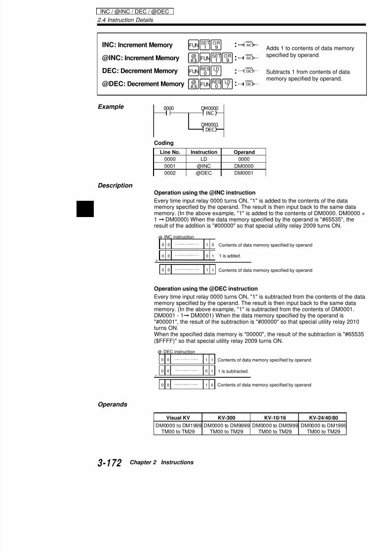
7/18/2019 Keyence Programming
http://slidepdf.com/reader/full/keyence-programming 196/392
2
Description Operation using the @INC instruction
Every time input relay 0000 turns ON, "1" is added to the content
memory specified by the operand. The result is then input back tmemory. (In the above example, "1" is added to the contents of D1 DM0000) When the data memory specified by the operand iresult of the addition is "#00000" so that special utility relay 2009
Operation using the @DEC instruction
Every time input relay 0000 turns ON, "1" is subtracted from the memory specified by the operand. The result is then input back tmemory. (In the above example, "1" is subtracted from the conteDM0001 - 1 DM0001) When the data memory specified by the"#00001", the result of the subtraction is "#00000" so that speciaturns ON.When the specified data memory is "00000", the result of the sub
0001 @INC DM0000
0002 @DEC DM0001
Contents of data memory specified by operand
Contents of data memory specified by operand
1 is added.
0 0 1 0
@
0 0 0 1+
0 0 1 1
INC instruction
Key operation
Arithmetic flag
2009 Turns ON when the result is "0" after an result is "$FFFF (#65535)" after DEC opetimes.
2010 Turns ON when the internal register is "0tion. Turns OFF at other times.
2011, 2012 No change
Note: When an every-scan type INC/DEC instruction instruction is executed every scan time while input rel
@
#,$ FUN
FUN
@#,$ FUN
FUNSET
1OR9
LD7
RES0
ENTR-SRCH
ENTR-SRCH
Operand
ENTR-SRCH
ENTR-SRCH
Operand

7/18/2019 Keyence Programming
http://slidepdf.com/reader/full/keyence-programming 197/392
instruction is executed every scan time while input rel
Use a differentiation type instruction (@INC or @DEConly once when input relay 0000 turns ON, as shown
Tips
When using DM0000 as an UP/DOWN counterPerforms an UP count (addition) when input relay 000Performs a DOWN count (subtraction) when input rela
Applications of INC/DEC instructions
UP/DOWN count
Performs an UP count when input relay 0000 turns ONPerforms a DOWN count when input relay 0001 turnsWrites the count value into DM0000.Reset input relay is 0005.
0000 DM0000INC
0001 DM0000DEC
#00000LDA
2008 DM0000STA
0000 D0000 DM0000INC
S t #00000 t DM
2.4 Instruction Details
Total count 1
Writes the total count of 4 lines (0000 to 0003) into DM0000.Reset input relay is 0005.
Coding
#00000LDA
2008
0000
DM0000STA
0005 #00000DW
DM0000INC
0001 DM0000INC
0002 DM0000INC
0003 DM0000INC
DM0000Clears DM0000 to #00000 when
Sets #00000 to DM0000 at startu
Increments DM0000 by 1 at UP e
Increments DM0000 by 1 at UP e
Increments DM0000 by 1 at UP e
Increments DM0000 by 1 at UP e
INC / @IN
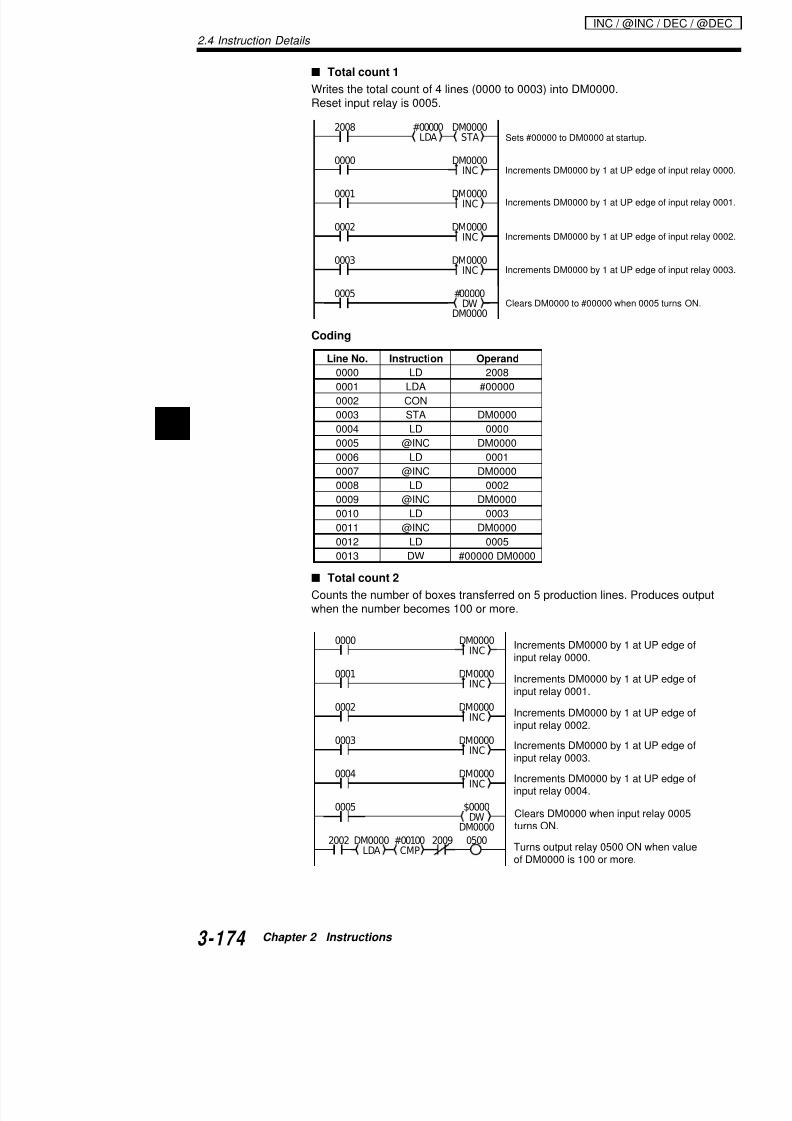
7/18/2019 Keyence Programming
http://slidepdf.com/reader/full/keyence-programming 198/392
2
Cod g
Total count 2
Counts the number of boxes transferred on 5 production lines. Pwhen the number becomes 100 or more.
Line No. Instruction Operand
0000 LD 2008
0001 LDA #00000
0002 CON
0003 STA DM00000004 LD 0000
0005 @INC DM0000
0006 LD 0001
0007 @INC DM0000
0008 LD 0002
0009 @INC DM0000
0010 LD 0003
0011 @INC DM0000
0012 LD 00050013 DW #00000 DM0000
0000 DM0000INC
0001 DM0000INC
Increments DM0000 by 1 at
input relay 0000.
Increments DM0000 by 1 at
Coding
Programming technique
Two kinds of instructions can be used for the countinginstruction and an INC instruction with data memory.The following examples show how to program the tota
Line No. Instruction Operand Line No.
0000 LD 0000 0011
0001 @INC DM0000 0012
0002 LD 0001 0013
0003 @INC DM0000 0014
0004 LD 0002 0015
0005 @INC DM0000 00160006 LD 0003 0017
0007 @INC DM0000 0018
0008 LD 0004 0019
0009 @INC DM0000 0020
0010 LD 0005
INC / @INC / DEC / @DEC

7/18/2019 Keyence Programming
http://slidepdf.com/reader/full/keyence-programming 199/392
As the example of the INC instruction shows, using disimplifies the program even for the same control.Simpler programming reduces the time for debugging
It is convenient to use the CMP instruction for compar
OR instruction
Compare the following two programs.With program 1), input relays 0000 through 0004 are ithey turn ON simultaneously.With program 2), when some input relays 0000 througneously, duplicated inputs are ignored.
Use the appropriate program according to your applic
0005 DM0001STA
C001LDA
#09999
0000C001
DM0002STA
C002LDA
#09999
0001C002
DM0003
STA
C003
LDA
#09999
0002C003
DM0004STA
C004LDA
#09999
0003C004
DM0005STA
C005LDA
#09999
0004C005
DM0000STA
DM0005ADD
DM0004ADD
DM0003ADD
DM0002ADD
DM0001LDA
2002 0005
0000
0001
0002
0003
0004
Programminwith data me
Programming with the C instruction
2.4 Instruction Details
Example
Coding
MPX:
@MPX:
DMX:
@DMX:
Converts 4-bit daregister into 16-bdata to be conveoperand.
@#,$
FUN
FUN
@#,$
FUN
FUN
LD7
LD7
SET1
ANL2
SET
1
ANL
2
ANL2
ANL2
#nMPX
#nMPX
DMX
DMX
Multiplexer
(4-to-16 decoder),
Demultiplexer
(16-to-4 encoder)
0000 0000LDA
#1MPX
1000STA
0001 0100LDA DMX
DM0000STA
Line No. Instruction Operand
0000 LD 0000
:
:
:
: Converts positioncant bit with 1 in
into 4-bit data.
MPX / @M

7/18/2019 Keyence Programming
http://slidepdf.com/reader/full/keyence-programming 200/392
2
Operands
#0 to #3
Key operation
0000 LD 0000
0001 LDA 0000
0002 CON
0003 MPX #1
0004 CON
0005 STA 1000
0006 LD 0001
0007 LDA 0100
0008 CON
0009 DMX
0010 CON
0011 STA DM0000
@# $ FUN
FUN
@#,$ FUN
FUNSET
1OR9
LD7
RES0
ENTR-SRCH
ENTR-SRCH
Operand
ENTR-SRCH
ENTR-SRCH
Operand
Description
Operation with the MPX instruction
When input relay 0000 is ON, the ON/OFF status of inis transferred to the internal register. The section of ththe operand (input relays 0004 through 007: 4 bits) is number (0 to F). Only the bit at the position specified bset to "1" and other bits are set to "0". The resulting O
the internal register, and then output to inputs 1000 toIn the example, when the value specified by inputs 00"A", internal relay 1010 turns ON.
1 0 1 0
#3 #2 #1
A
#0
0 0 0 0 0 1 0 0 0 0 0 0 0 0 0 0
F E D C B A 9 8 7 6 5 4 3 2 1 0
No. represented binternal register sp
Operand
Internal register
Internal register
MPX / @MPX / DMX / @DMX
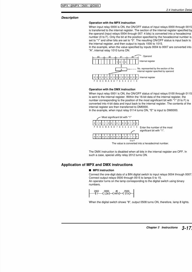
7/18/2019 Keyence Programming
http://slidepdf.com/reader/full/keyence-programming 201/392
Operation with the DMX instruction
When input relay 0001 is ON, the ON/OFF status of inis sent to the internal register. Within the 16-bit data onumber corresponding to the position of the most signconverted into 4-bit data and input back to the internainternal register are then transferred to DM0000.In the example, when input relay 0114 turns ON, "E" i
The DMX instruction is disabled when all bits in the insuch a case, special utility relay 2012 turns ON.
Application of MPX and DMX instructions
0 to F
0 1 0 1 1 0 0 1 0 1 0 0 0 1 0 0
0 0 0 0 0 0 0 0 0 0 0 0 1 1 1 0
F E D C B A 9 8 7 6 5 4 3 2 1 0
The value is converted into a hexadeci
Most significant bit with "1"
Enter the num
significant bit
2.4 Instruction Details
DMX instruction
Connect sensors 0 to 15 to input relays 0000 through 0015.Connect output relays 0500 through 0503 to the one-digit data ofThe sensors which are currently ON are shown by the BIN indica* Assume that several sensors do not turn on simultaneously.
When sensor 8 is ON, the indicator shows "8".
Output of error input No. in BCD
Outputs the error sensor No. from input relay 0000 to 0015 to ou0507 in 2-digit BCD.
2002 0000LDA DMX
0500STA
0000
LDA
2002
2002
DMX
TBCD$00FFANDA
0500STA Converts internal register data to
ANDA instruction, and outputs the
Converts the most significant bit o0015) to 4-bit BIN data and sends
MPX / @M
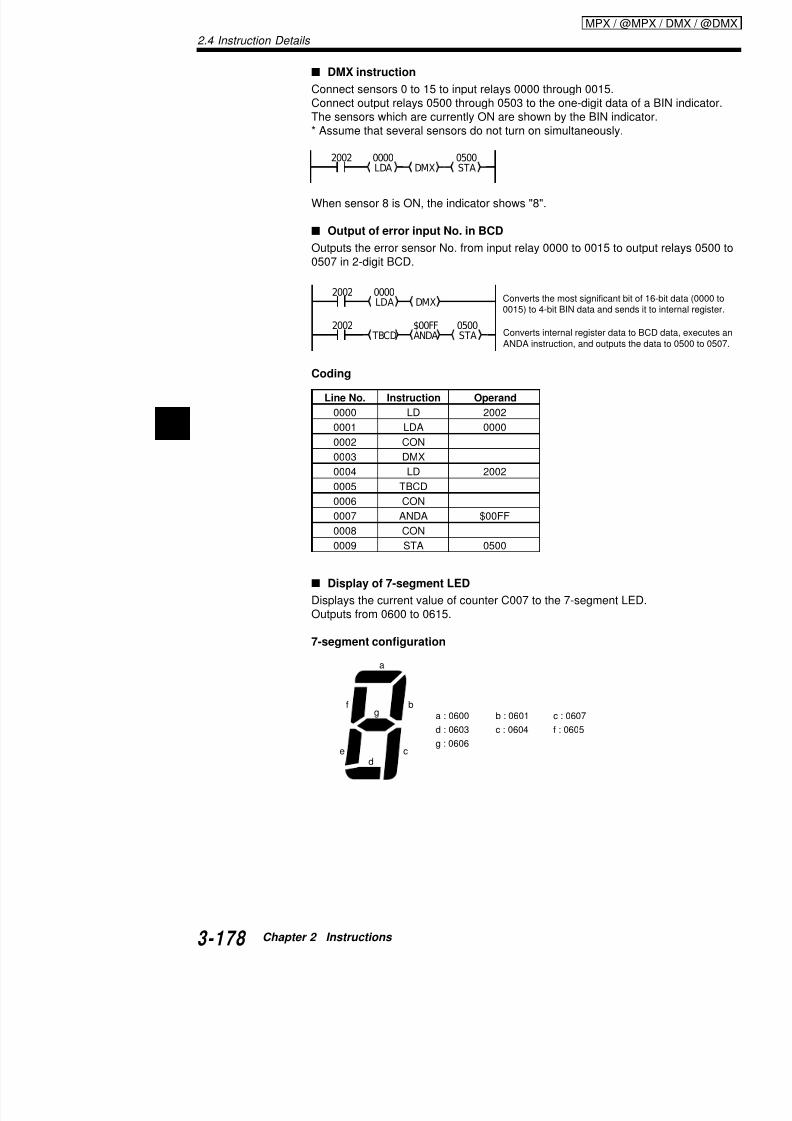
7/18/2019 Keyence Programming
http://slidepdf.com/reader/full/keyence-programming 202/392
2
a
Coding
Display of 7-segment LED
Displays the current value of counter C007 to the 7-segment LEDOutputs from 0600 to 0615.
7-segment configuration
Line No. Instruction Operand
0000 LD 2002
0001 LDA 0000
0002 CON
0003 DMX
0004 LD 2002
0005 TBCD
0006 CON
0007 ANDA $00FF
0008 CON
0009 STA 0500
ANDA instruction, and outputs the
C000LDA
#0MPX
C000 #00009C0000000
1000STA
$003F
LDA
0600
STA
1000
0
$0006LDA
0600STA
10011
$005BLDA
0600STA
10022
$004FLDA
0600STA
10033
$0066LDA
0600STA
1004
4
$006DLDA
0600STA
10055
Converts the counter value to 16-bitdata using the MPX instruction.
7-segme
Auto-resetcounter
Sends internal register data tooutput relays starting from 0600.
MPX / @MPX / DMX / @DMX

7/18/2019 Keyence Programming
http://slidepdf.com/reader/full/keyence-programming 203/392
$007DLDA
0600STA
0600STA
10066
$0007LDA
10077
$007FLDA 0600STA1008 8
$006FLDA
0600STA
10099
Line No. Instruction Operand Line No.
0000 LDB C000 00240001 C 000 #00009 0000 0025
0002 CON 0026
0003 LDA C000 0027
0004 CON 0028
0005 MPX #0 0029
0006 CON 0030
0007 STA 1000 0031
0008 LD 1000 0032
0009 LDA $003F 00330010 CON 0034
Coding
2.4 Instruction Details
Example
Coding
TBCD: Transfer BCD
@TBCD: Transfer BCD
TBIN: Transfer BIN
@TBIN: Transfer BIN
Converts contents of i(16-bit binary) into 4-d
Converts contents of i(4-bit binary) into 16-d
@#,$
FUN
FUN
@#,$
FUN
FUN
LD7
LDB4
LDB4
AND8
LD7
LDB4
LDB4
AND8
TBCD
TBCD
TBIN
TBIN
TBCD
TBIN
0000
0001
DM0000LDA
DM0001STA
DM0010LDA
DM0011STA
Line No. Instruction Operand
0000 LD 0000
0001 LDA DM0000
:
:
:
:
TBCD / @TBC

7/18/2019 Keyence Programming
http://slidepdf.com/reader/full/keyence-programming 204/392
2
Operands
Key operation
0001 LDA DM0000
0002 CON
0003 @TBCD
0004 CON
0005 @STA DM0001
0006 LD 00010007 LDA DM0010
0008 CON
0009 @TBIN
0010 CON
0011 @STA DM0011
@#,$ FUN
FUN
@#,$ FUN
FUNLD7
LDB
4
LDB4
AND
8
ENTR-SRCH
ENTR-SRCH
ENT
R-SRCH
ENT
R-SRCH
Description
Operation using the TBCD instruction
When input relay 0000 turns ON, the contents of DM0internal register. The contents of the internal register (verted into 4-digit BCD data, which is input back to thetransferred to DM0001.
Operation using the TBIN instruction
When input relay 0001 turns ON, the contents of DM0internal register. The contents of the internal register (
Data is converted into B
103
(0)102
(0)101
(2)100
(4)
0 0 0 0 0 0 0 0 0 0 0 1 1 0 0 0
216 20
0 0 0 0 0 0 0 0 0 0 1 0 0 1 0 0
8 4 2 1 8 4 2 1 8 4 2 1 8 4 2 1
TBCD / @TBCD / TBIN / @TBIN

7/18/2019 Keyence Programming
http://slidepdf.com/reader/full/keyence-programming 205/392
verted into 16-bit binary data, which is input back to thtransferred to DM0011.
Note 1: The TBCD instruction can only convert data uconversion of data of "#10000" or greater is attempted
turns ON and the conversion is disabled.
Note 2: When the data in the internal register is not B2012 turns ON and the TBIN instruction is disabled.
Applications of TBCD instruction
Output of 4-digit BCD data
Outputs the current value of counter C001 to 0700 to
Data is converted into bin
(5)103
(5)
102(5)101
(5)100
0 0 0 1 0 1 0 1 1 0 1 1 0 0 1 1
0 1 0 1 0 0 0 1 0 1 0 1 0 1 0 1
8 4 2 1 8 4 2 1 8 4 2 1 8 4 2 1
D15 D14 D13 D12 D11 D10 D9 D8 D7 D6 D5 D4 D3 D2 D1 D0
0001 #09999C001 S t C001
2.4 Instruction Details
Output of 8-digit BCD data
Outputs the calculated product of DM0000 x DM0001 (0 to 99999digits at maximum as below:
High-order 4-digit BCD data To 0600 to 0615Low-order 4-digit BCD data To 0500 to 0515
DM0000LDA
DM0001MUL
DM0101STA
#10000DIV
TM01LDA TBCD
0500STA
2002
TM00DM0000 x DM0001 =
TM00
0600 to 0615 0500 to 0515
... TM01
÷ #10000
=
Display
Internal register
High-order 4 digits Low-order 4 digits
High-order 4 digits
Internal register
Internal register
TM00
Low-order 4 digits Remainder
High-order 4 digits Low-order 4 digits
TBCD / @TBC

7/18/2019 Keyence Programming
http://slidepdf.com/reader/full/keyence-programming 206/392
2
0400LDA
C001STA
2002 TBIN Converts data of 0400 to 0415 to
into C001.
Coding
Application of TBIN instruction
Input of 4-digit BCD data
Sets 4 digits of the BCD digital switch (0400 to 0415) as the coun
DM0101LDA TBCD
0600STA
Line No. Instruction Operand Line No. Instruct0000 LD 2002 0010 CON
0001 LDA DM0000 0011 TBCD
0002 CON 0012 CON
0003 MUL DM0001 0013 STA
0004 CON 0014 CON
0005 DIV #10000 0015 LDA
0006 CON 0016 CON
0007 STA DM0101 0017 TBCD
0008 CON 0018 CON
0009 LDA TM01 0019 STA
Example
Coding
ASC: ASCII Convert
@ASC: ASCII Convert
RASC: Reverse ASCII Convert
@RASC: Reverse ASCII Convert
Convertsof internacode.
Convertsrepresen
@#,$
FUN
FUN
ORL3
ORL3
@#,$
FUN
FUN
RES0
ANL2
ANL2
ANL2
RES0
ANL2 ASC
ASC
RASC
RASC
ASC
RASC
0000
0001
DM0000LDA
DM0001STA
DM0010LDA
DM0011STA
Line No. Instruction Operand
0000 LD 0000
0001 LDA DM0000
ASC / @ASC / RASC / @RASC
:
:
:
:
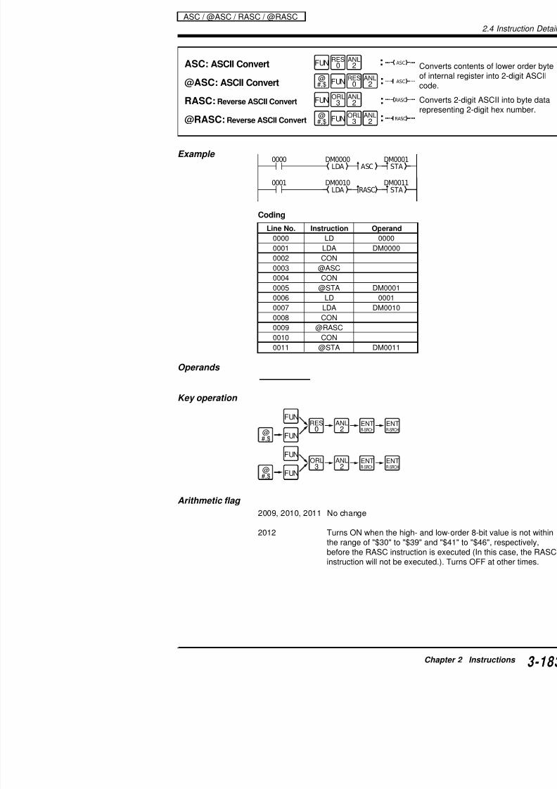
7/18/2019 Keyence Programming
http://slidepdf.com/reader/full/keyence-programming 207/392
Operands
Key operation
0001 LDA DM0000
0002 CON
0003 @ASC
0004 CON
0005 @STA DM0001
0006 LD 00010007 LDA DM0010
0008 CON
0009 @RASC
0010 CON
0011 @STA DM0011
ORL
3@#,$ FUN
FUN
@#,$ FUN
FUNRES
0
ANL
2
ANL2
ENTR-SRCH
ENTR-SRCH
ENTR-SRCH
ENTR-SRCH
2.4 Instruction Details
Description
Operation using the ASC instruction
When input relay 0000 turns ON, the contents of DM0000 are trainternal register. The contents of the internal register (low-order 8cal value) are converted into 2-digit ASCII code. This 2-digit codeinternal register, and then transferred to DM0001.
Operation using the RASC instruction
When input relay 0001 turns ON, the contents of DM0010 are trainternal register. The contents of the internal register (2-digit ASCverted into a low-order 8-bit, 2-digit numeric value. This 2-digit nuback to the internal register, then transferred to DM0011..
1 0 1 0 0 1 0 1
0 1 0 0 0 0 0 1 0 0 1 1 0 1
4 1 3 5
A 5
0 1
ASC / @ASC
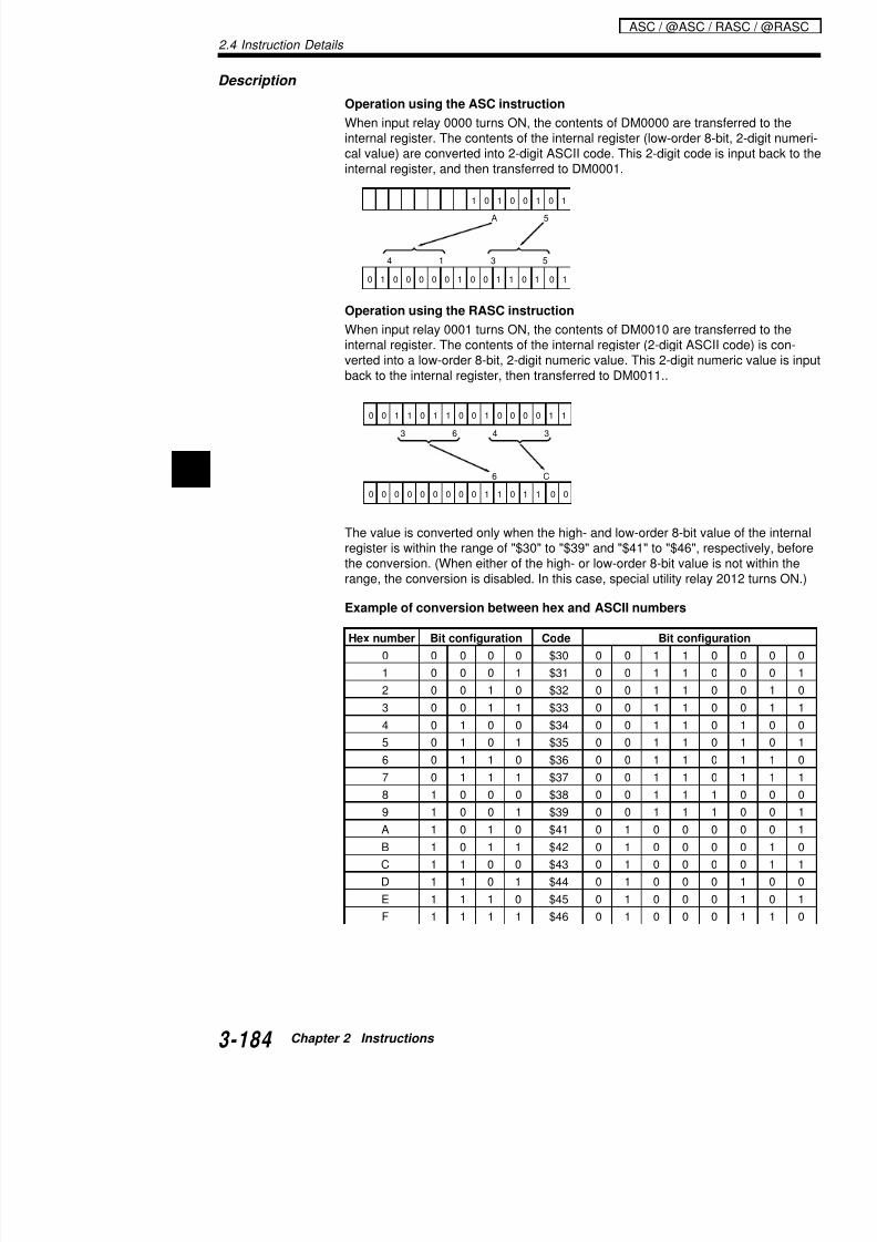
7/18/2019 Keyence Programming
http://slidepdf.com/reader/full/keyence-programming 208/392
2
Hex number Bit configuration Code Bit config
0 0 0 0 0 $30 0 0 1 1
1 0 0 0 1 $31 0 0 1 1
2 0 0 1 0 $32 0 0 1 1
3 0 0 1 1 $33 0 0 1 1
4 0 1 0 0 $34 0 0 1 1
5 0 1 0 1 $35 0 0 1 1
6 0 1 1 0 $36 0 0 1 1
The value is converted only when the high- and low-order 8-bit varegister is within the range of "$30" to "$39" and "$41" to "$46", rthe conversion. (When either of the high- or low-order 8-bit valuerange, the conversion is disabled. In this case, special utility relay
Example of conversion between hex and ASCII numbers
0 0 0 0 0 0 0 0 0 1 1 0 1 1
4 33 6
6 C
0 0
0 0 1 1 0 1 1 0 0 1 0 0 0 0 1 1
Example
Coding
ROOT: Square Root
@ROOT: Square Root
Takes squarehigher order border byte), aregister.
ROOT
ROOT
ORB6
ORL3
ORB6
ORL3
@#,$
FUN
FUN
ROOT0000 TM00STADM0001LDA DM0000LDA DM0100STA
Line No. Instruction Operand
0000 LD 0000
0001 LDA DM0001
0002 CON0003 STA TM00
0004 CON
0005 LDA DM0000
CON
:
:
ROOT / @ROOT
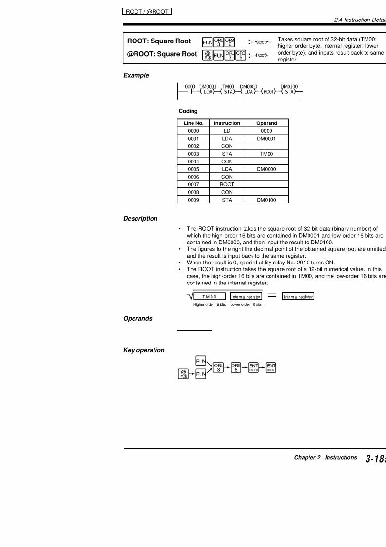
7/18/2019 Keyence Programming
http://slidepdf.com/reader/full/keyence-programming 209/392
Description
• The ROOT instruction takes the square root of 32-which the high-order 16 bits are contained in DM00contained in DM0000, and then input the result to
• The figures to the right the decimal point of the obtand the result is input back to the same register.
• When the result is 0, special utility relay No. 2010 • The ROOT instruction takes the square root of a 3case, the high-order 16 bits are contained in TM00contained in the internal register.
Operands
0006 CON
0007 ROOT
0008 CON
0009 STA DM0100
T M 0 0 Internal register Internal registe
Higher order 16 bits Lower order 16 bits
2.4 Instruction Details
Change in status of special utility relays (arithmetic flags) by ainstructions (1/3)
Instruction Mnemonic Operand A < 0 A = 0 A >2009 2010 201
DATAMEMORY DW $,# constant — — —WRITE
3-136 Relay No. — 5 —
LOAD A LDA Timer/counter No. — 5 —
3-140 [FUN23] Data memory No. — 5 —
$,# constant — 5 —
# TM — 5 —
Relay No. — — —
STORE A STA Timer/counter No. — — —
3-140 [FUN42] Data memory No. — — —
# TM — — —
COMPARECMP
Data memory No. 1 2 3
3-146 [FUN04]
$,# constant 1 2 3
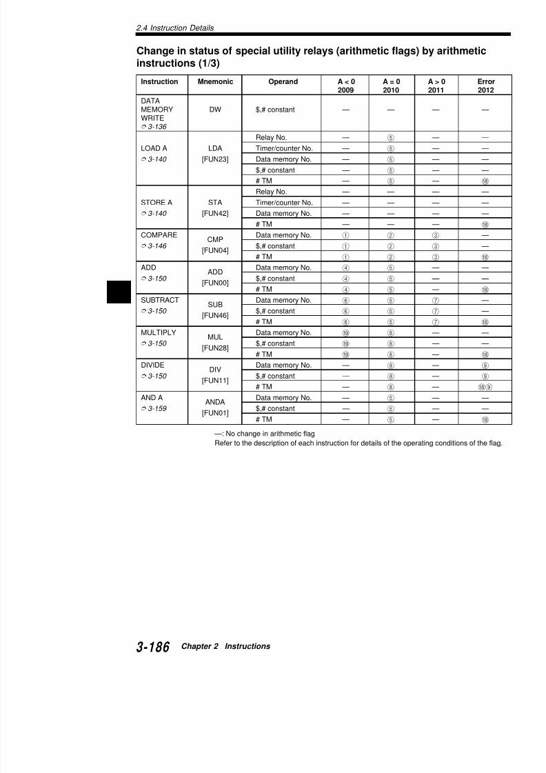
7/18/2019 Keyence Programming
http://slidepdf.com/reader/full/keyence-programming 210/392
2
3 6[FUN04]
$,# co sta t 1 2 3
# TM 1 2 3
ADDADD
Data memory No. 4 5 —
3-150 [FUN00]
$,# constant 4 5 —
# TM 4 5 —SUBTRACT
SUBData memory No. 6 5 7
3-150 [FUN46]
$,# constant 6 5 7
# TM 6 5 7
MULTIPLYMUL
Data memory No. I 8 —
3-150 [FUN28]
$,# constant I 8 —
# TM I 8 —
DIVIDEDIV
Data memory No. — 8 —
3-150 [FUN11] $,# constant — 8 —# TM — 8 —
AND AANDA
Data memory No. — 5 —
3-159 [FUN01]
$,# constant — 5 —
# TM — 5 —
—: No change in arithmetic flag
Refer to the description of each instruction for details of the operating co
Change in status of special utility relays (arithmetic flainstructions (2/3)
Instruction Mnemonic Operand A < 0 A = 02009 2010
OR AORA
Data memory No. — 5
3-161[FUN31]
$,# constant — 5
# TM — 5
EXCLUSIVEEORA
Data memory No. — 5
OR A[FUN15]
$,# constant — 5
3-164 # TM — 5
SHIFTSRA
Number of shifts 0 5
RIGHT A[FUN41]
3-166
SHIFTSLA
Number of shift 0 5
LEFT A[FUN40]
3-166 ROTATE
RRANumber of rotations 0 5
RIGHT A[FUN37]
3-169
ROTATE Number of rotations 0 5

7/18/2019 Keyence Programming
http://slidepdf.com/reader/full/keyence-programming 211/392
ROTATERLA
Number of rotations 0 5
LEFT A[FUN40]
3-169
COMPLE-COM
— 5
MENT
[FUN05] 3-171
INCREMENTINC
Data memory No. A 5
MEMORY[FUN19]
3-172
DECRE-MENT DEC Data memory No. B 5
MEMORY [FUN07] 3-172
MULTI-
MPX
Digit No. — —
PLEXER [FUN27] 3-176
DEMULTI-DMX
— —PLEXER
[FUN12] 3-176
TRANSFERTBCD
— —BCD
[FUN47] 3-180
TRANSFER
TBIN
— —
BIN[FUN48]
3-180
2.4 Instruction Details
Change in status of special utility relays (arithmetic flags) by ainstructions (3/3)
1 When the result of COMPARE is negative, the relay turns ONnot negative, the relay remains OFF.
2 When the result of COMPARE is "0", the relay turns ON. Whe"0", the relay remains OFF.
3 When the result of COMPARE is positive, the relay turns ON.not positive, the relay remains OFF.
4 When the result of the arithmetic operation exceeds the 16-bitthe relay turns ON. When the result is within the 16-bit range,OFF.
5 When, as a result of the arithmetic operation, the data in the i"0", the relay turns ON. When the data is not "0", the relay rem
6 When the result of the arithmetic operation is negative, the reWhen the result is not negative, the relay remains OFF.
7 When the result of the arithmetic operation is positive, the relaWhen the result is not positive, the relay remains OFF.
8 Wh lt f th ith ti ti ll f th 32 bit
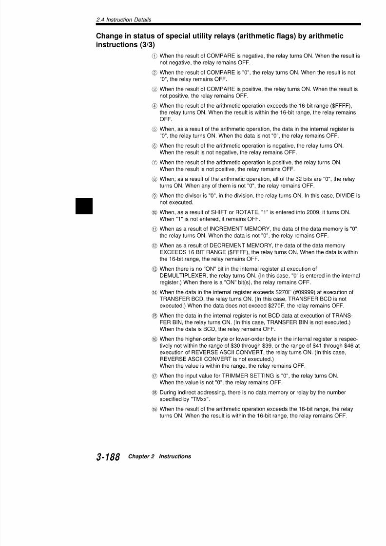
7/18/2019 Keyence Programming
http://slidepdf.com/reader/full/keyence-programming 212/392
2
8 When, as a result of the arithmetic operation, all of the 32 bitsturns ON. When any of them is not "0", the relay remains OFF
9 When the divisor is "0", in the division, the relay turns ON. In tnot executed.
0 When, as a result of SHIFT or ROTATE, "1" is entered into 20When "1" is not entered, it remains OFF.
A When as a result of INCREMENT MEMORY, the data of the dthe relay turns ON. When the data is not "0", the relay remain
B When as a result of DECREMENT MEMORY, the data of the EXCEEDS 16 BIT RANGE ($FFFF), the relay turns ON. Whethe 16-bit range, the relay remains OFF.
C When there is no "ON" bit in the internal register at execution DEMULTIPLEXER, the relay turns ON. (In this case, "0" is enregister.) When there is a "ON" bit(s), the relay remains OFF.
D When the data in the internal register exceeds $270F (#09999TRANSFER BCD, the relay turns ON. (In this case, TRANSFexecuted.) When the data does not exceed $270F, the relay r
E When the data in the internal register is not BCD data at exec
FER BIN, the relay turns ON. (In this case, TRANSFER BIN iWhen the data is BCD, the relay remains OFF.
2.5 Programming Notes
This section describes important points and precautiograms.
Circuits that must be modified
1. The circuit shown below left cannot be programmeright.
2. Output is disabled in 0500 in the circuit shown beloshown on the right, output of one scan only is disa
C D
A B 0500
E
A E
C E 0500
A
D
B
C
A 1000 A 1000 0500

7/18/2019 Keyence Programming
http://slidepdf.com/reader/full/keyence-programming 213/392
3. If the same coil is used in two positions, the latter pcoil in the former position is ignored.
4. The circuit shown below left cannot be programmeright.
1000
A 1000
0500
A 1000 0500
A 1000
E
A
C
B 0500
0500
A B 0500
C E
A B C
D E
0500 B C
D E
A 0500
2.5 Programming Notes
0500
2002 #0010 T000
0500
#0010 T000
A B D E E0500
C
A B
C
Programming precautions
1. A coil output or timer/counter cannot be connected directly frooutput coil or a timer/counter is required, insert a 'b' contact ofutility relay, a 'b' contact of an unused special utility relay, or a2002 (always ON) as a dummy.
2. A contact cannot be connected to an output line.
3. Make sure that every contact/coil is located on a path from a line. Make sure that there are no unconnected portions.
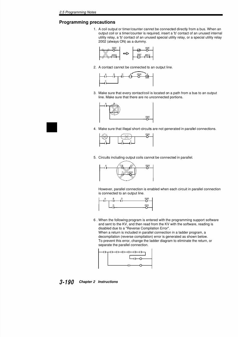
7/18/2019 Keyence Programming
http://slidepdf.com/reader/full/keyence-programming 214/392
2
0500
C
D
B C 0500
0501
A
B C
0500
A
A B D 0500
D 0501
4. Make sure that illegal short-circuits are not generated in para
5. Circuits including output coils cannot be connected in parallel
However, parallel connection is enabled when each circuit in is connected to an output line.
Chapter 3
InterruptsThe interrupt processing function executes an interrupinput or request from the high-speed counter comparatered during KV operation.This chapter describes the types of interrupt factors as

7/18/2019 Keyence Programming
http://slidepdf.com/reader/full/keyence-programming 215/392
This chapter describes the types of interrupt factors asencountered during interrupt processing.
For KV-10/80 Series, see Chapter 6.
3.1 Interrupt Instructions ...........................
3.2 Interrupt Processing ............................
3.2.1 Interrupt Processing ....................................3.2.2 Types of Interrupts ......................................3.2.3 Interrupt Priority...........................................3.2.4 Interrupt Program ........................................
3.3 Direct Input/Output ...............................
3.3.1 Direct Input ..................................................3.3.2 Direct Output ...............................................
3.4 Applications of Interrupt Programs ..
3.4.1 Interrupt with a Signal Converter.................3.4.2 Interrupt with a High-speed Counter ...........3.4.3 Measuring the ON Time of High-speed Puls3.4.4 Measuring the Period in which a Target Pas
Two Points ..................................................
3.1 Interrupt Instructions
VisualKV
Series
3.1 Interrupt Instructions
This section describes the INT, RETI, DI, and EI instructions useprocessing.
INT: Interrupt
RETI: Return Interrupt
Executes interrupt betweinstructions at rising or fa
specified by operand.
Represents termination o
FUN
FUN LDB
4
RES0
ANL2
ORL3
RETI
INTnnnn
0500
0000
T000 0500
#00020
T000
a)
0000
Normal
input
Example
Coding for normal in
(Input ON time: 10 ms min.)
Line No. Instructio
0000 LD
0001 OR
0002 TMR
0003 ANB
0004 OUT
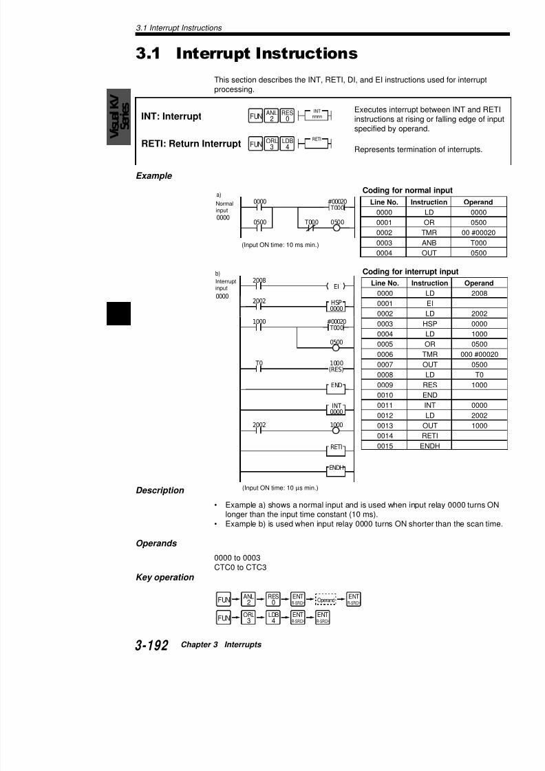
7/18/2019 Keyence Programming
http://slidepdf.com/reader/full/keyence-programming 216/392
3
Coding for interrupt Interruptinput
0004 OUT
Line No. Instructi
0000 LD0001 EI
0002 LD
0003 HSP
0004 LD
0005 OR
0006 TMR
0007 OUT
0008 LD0009 RES
0010 END
0011 INT
0012 LD
0013 OUT
0014 RETI
0015 ENDH
1000
0500
#00020 T000
1000
2002
b)
0000
2008EI
END
INT0000
HSP0000
RETI
ENDH
2002
T0 1000(RES)
DI: Interrupt Disabled
EI: Interrupt Enabled
Disab
Enab
Example
Coding
FUN
FUN
RES0
ORL3
DI
EISET
1
AND8
1000EI
DI1000
Line No. Instruction Operand
0000 LD 0000
0001 EI• •• •• •
0021 LDB 1000
0022 DI• •

7/18/2019 Keyence Programming
http://slidepdf.com/reader/full/keyence-programming 217/392
Description
• When 1000 is ON, execution of interrupt is enabled• When 1000 is OFF, execution of interrupt is disabl• Interrupts are enabled between EI instruction and • Once an EI instruction is executed, an interrupt is e
executed.• Any interrupt is disabled when the Visual KV Serie• The DI instruction disables execution of an interrup
temporarily disable an interrupt.• The EI instruction enables execution of an interrup
release an interrupt that was disabled by a DI instr• To execute another interrupt during execution of th
instruction in this first interrupt. EI-DI instruction se
Note 1: When any interrupt occurs between DI and Eperiod), the disabled interrupt is stored (to 8 levels maexecuted as soon as an EI instruction is executed.
Note 2: If an INT CTC instruction is stored before a R
ecuted, the stored INT CTC is deleted.
• •• •
3.2 Interrupt Processing
Vis
ualKV
S
eries
3.2 Interrupt Processing
This section describes interrupt processing.
3.2.1 Interrupt Processing
Outline
Normally, a PLC processes a ladder sequence program by repeainput processing, program execution, and output processing. Thewhich are shorter than the scan time cannot be received.When the interrupt processing function is used, a process can beinstant of the interrupt, independent of the scan time.When any interrupt occurs, the Visual KV series suspends the cuprogram and executes the interrupt program in accordance with tWhen the interrupt program completes, the Visual KV resumes e
suspended program. For more about scan time, refer to "1.1.2 Scan Time" (p. 3-3).
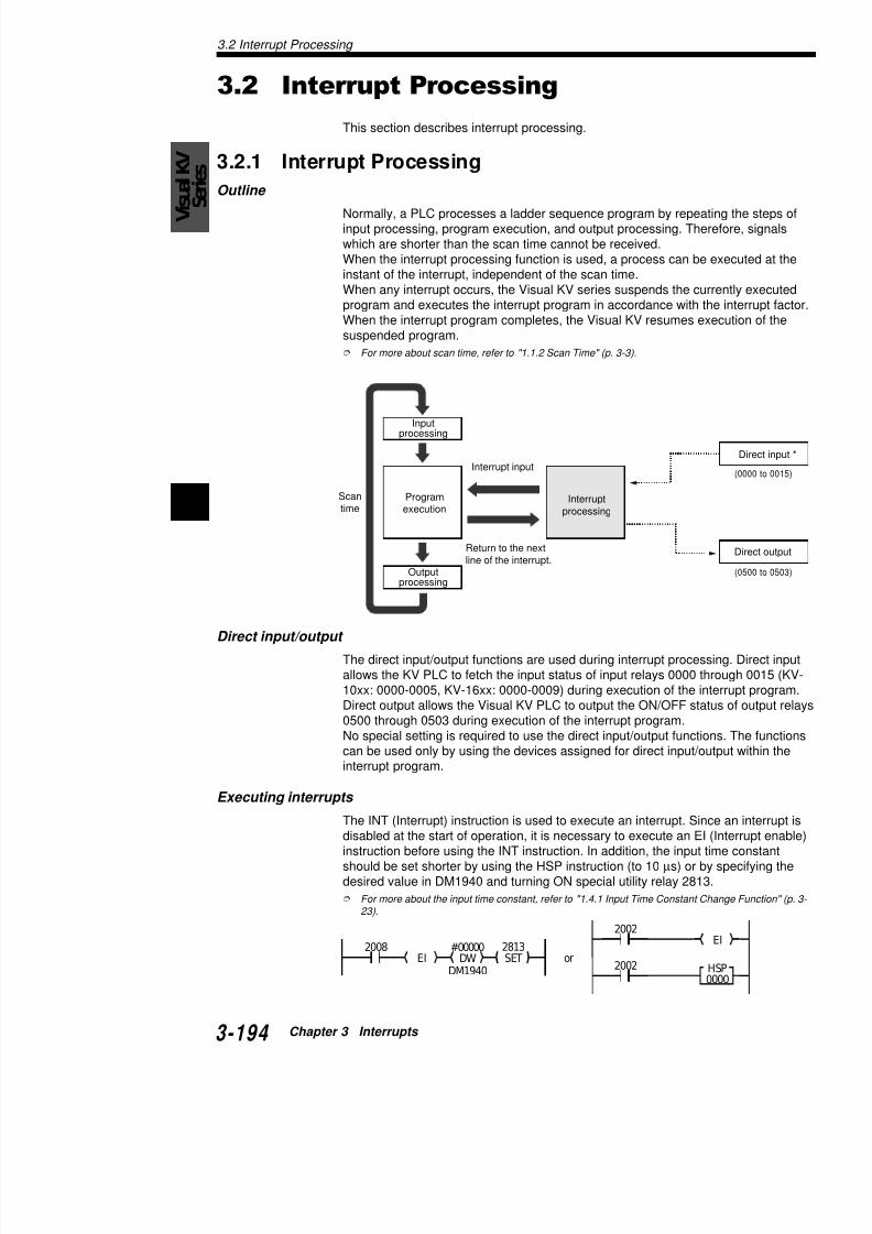
7/18/2019 Keyence Programming
http://slidepdf.com/reader/full/keyence-programming 218/392
3
Direct input/output
The direct input/output functions are used during interrupt procesallows the KV PLC to fetch the input status of input relays 0000 t10xx: 0000-0005, KV-16xx: 0000-0009) during execution of the inDirect output allows the Visual KV PLC to output the ON/OFF sta0500 through 0503 during execution of the interrupt program.
No special setting is required to use the direct input/output functiocan be used only by using the devices assigned for direct input/o
Inputprocessing
Programexecution
Outputprocessing
Scantime
Interrupt input
Return to the nextline of the interrupt.
Interruptprocessing
3.2.2 Types of Interrupts
Interrupts can be divided into two types: an interrupt binterrupt by the high-speed counter comparator. This sinterrupt types.
Interrupt by an external input
This interrupt is executed by input relays 0000 through
relay to specify the polarity of the interrupt factor to a
Interrupt by the high-speed counter comparator
This interrupt is executed when the current value of thmatches the preset value of the high-speed counter co
Polarity setting for interrupts by an external input
Turn ON the appropriate special utility relay to specify
or falling edge.The interrupt polarity can be changed as follows by se2402/2403 (INT0), 2404/2405 (INT1), 2410/2411 (INT
tpurretnIepyt
yaleR.oN
sutatS yaleR
.oN sutatS

7/18/2019 Keyence Programming
http://slidepdf.com/reader/full/keyence-programming 219/392
Use SET-RES instructions to turn the special utilitCAUTION
0TNI 2042
FFO
3042
FFOccotpurretnI
NO FFO
FFO NO ccotpurretnI
NO NO ccotpurretnI
1TNI 4042
FFO
5042
FFOccotpurretnI
NO FFO
FFO NO ccotpurretnI
NO NO ccotpurretnI
2TNI 0142
FFO
1142
FFOccotpurretnI
NO FFO
FFO NO ccotpurretnI
NO NO ccotpurretnI
3TNI 2142
FFO
3142
FFOccotpurretnI
NO FFO
FFO NO ccotpurretnI
NO NO ccotpurretnI
3.2 Interrupt Processing
Vis
ualKV
S
eries
• Use SET-RES instructions to turn the special utility relay• The input capture function stores the high-order bit data
bit high-speed counter is used. The data is undefined whspeed counter is used.
"4.4.1 24-bit High-speed Counter" (p. 3-221)
• Timing of the input capture execution depends on the inpspecified with special utility relays 2402 through 2405 and2413.
3.2.3 Interrupt Priority
When many interrupts occur sequentially, priority is given to the ioccurs earlier.When two or more interrupts occur simultaneously, priority is give0000, 0001, 0002, 0003, CTC2, CTC3, CTC0, and CTC1.
Note 1: While one interrupt is being executed, other interrupts arlevel interrupts are possible by placing an EI instruction within an
Note 2: When other interrupts occur during execution of an interrare stored up to 8 levels deep. The stored interrupts are executeof the previous interrupt, according to the priority order. Howeveruses the same device as a previous interrupt cannot be stored.
CAUTION
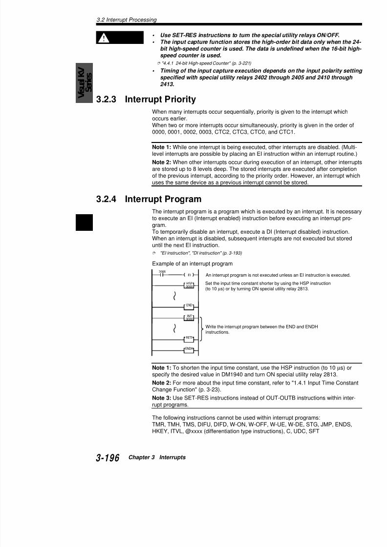
7/18/2019 Keyence Programming
http://slidepdf.com/reader/full/keyence-programming 220/392
3
uses the same device as a previous interrupt cannot be stored.
3.2.4 Interrupt Program
The interrupt program is a program which is executed by an interto execute an EI (Interrupt enabled) instruction before executing gram.To temporarily disable an interrupt, execute a DI (Interrupt disablWhen an interrupt is disabled, subsequent interrupts are not execuntil the next EI instruction.
"EI instruction", "DI instruction" (p. 3-193)
Example of an interrupt program
2008EI
HSP0000
END
INT0000
An interrupt program is not executed unless an EI inst
Set the input time constant shorter by using the HSP i(to 10 µs) or by turning ON special utility relay 2813.
Write the interrupt program between the END and ENinstructions.
2002
2008
HSP0000
HSP
EI
3.3 Direct Input/Output
This section describes direct input and output.
3.3.1 Direct Input
The direct input function is used during interrupt proce
KV PLC to fetch the input status of the input relays duprogram.
Direct input is available only with input relays 0000 thr0005, KV-16xx: 0000-0009). (KV-300: 0000-0005)
• The input time constant must be set to 10 µs by usturning ON special utility relay 2813.
• The direct input data is effective only within the inteinternal utility relay must be provided.
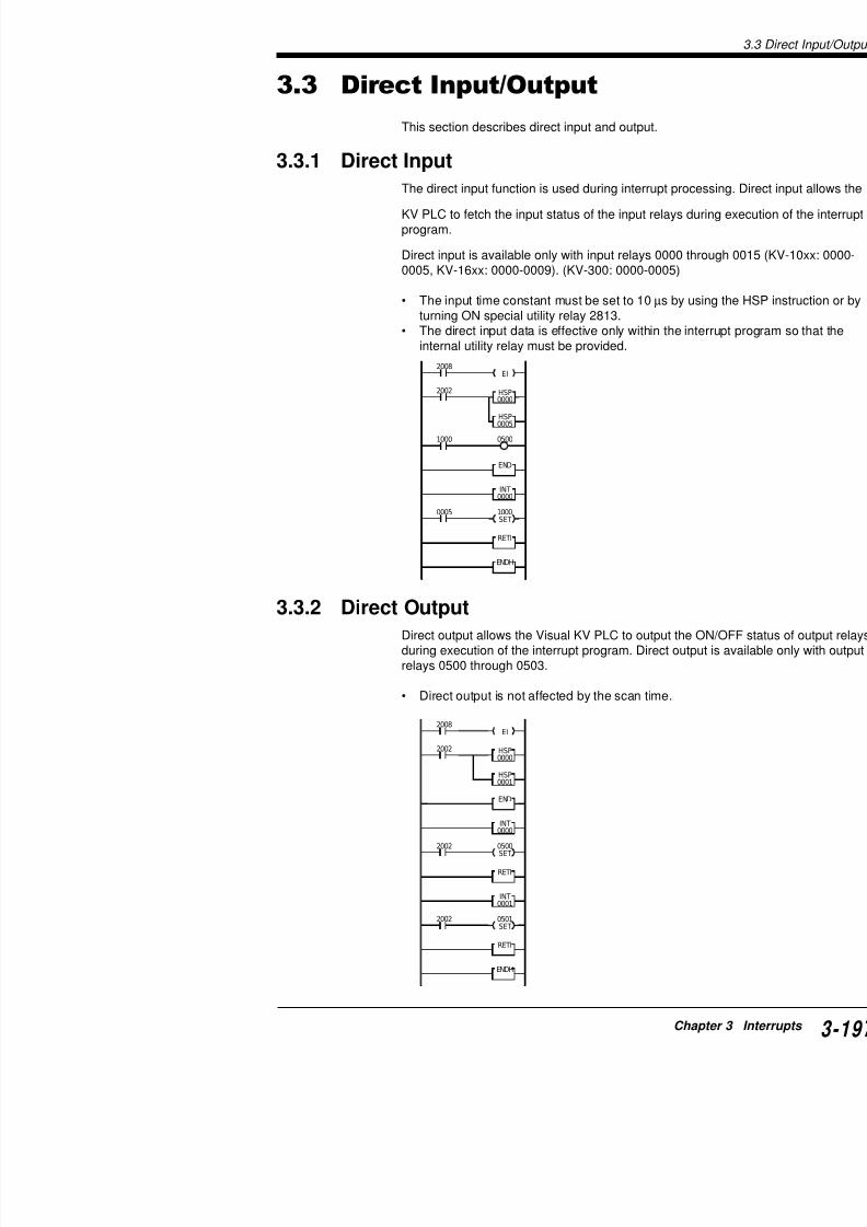
7/18/2019 Keyence Programming
http://slidepdf.com/reader/full/keyence-programming 221/392
END
INT0000
1000
0005
RETI
ENDH
0500
HSP0005
1000SET
2002
2008
EI
HSP
3.3.2 Direct OutputDirect output allows the Visual KV PLC to output the Oduring execution of the interrupt program. Direct outpurelays 0500 through 0503.
• Direct output is not affected by the scan time.
3.4 Applications of Interrupt Programs
Vis
ualKV
S
eries
3.4 Applications of Interrupt Progra
This section presents program examples of interrupt processing.
3.4.1 Interrupt with a Signal Converter
Outline
Converts the short pulses which are input by interrupt processingconstant width and then outputs them.
OFF
ON
OFF
ON
ONONON
1 sec
Scan
Input 0000
Output 0500
1 sec. 1 sec.
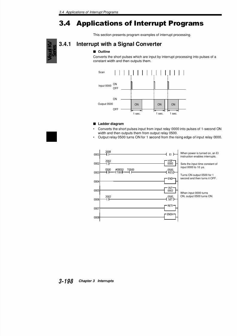
7/18/2019 Keyence Programming
http://slidepdf.com/reader/full/keyence-programming 222/392
3
0001
0002
0003
0004
0005
0006
2008EI
2002
2002
T00000500
HSP
0000
END
INT0002
RETI
#00010 T000
0500RES
0500
SET
Ladder diagram
• Converts the short pulses input from input relay 0000 into pulwidth and then outputs them from output relay 0500.
• Output relay 0500 turns ON for 1 second from the rising edge
1 sec. 1 sec. 1 sec.
When inpON, outp
When poinstructio
Sets the input 000
Turns ONsecond a
3.4 App
3.4.2 Interrupt with a High-speed Counter Outline
Uses the input value of a high-speed counter from one input rstatus of another input relay to control the ON/OFF status of a
Example: Filling control for medicine (tablets)
ON
OFF
ON
OFF
ON
OFF
ON
Output 0500
Scan
Input 0004
Input 0000
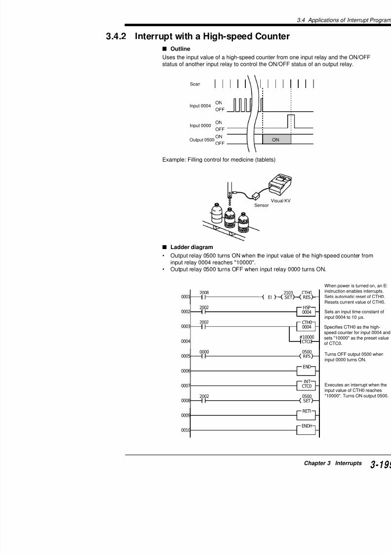
7/18/2019 Keyence Programming
http://slidepdf.com/reader/full/keyence-programming 223/392
0001
0002
0003
2008EI
2002 HSP0004
2002 CTH00004
#10000
CTH0RES
2103SET
Ladder diagram
• Output relay 0500 turns ON when the input value of the hiinput relay 0004 reaches "10000".
• Output relay 0500 turns OFF when input relay 0000 turns
SensorVisual KV
3.4 Applications of Interrupt Programs
Vis
ualKV
S
eries
3.4.3 Measuring the ON Time of High-speed Pulse
Outline
Measures the pulse width of the pulse input to an input relay.
Example: Measurement of workpiece length
OFF
ON
Sensor input 0000
Pulse width (µs)
Visual KV
Sensor
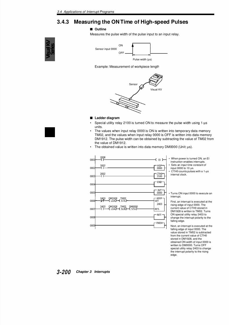
7/18/2019 Keyence Programming
http://slidepdf.com/reader/full/keyence-programming 224/392
3
0001
0002
0003
0004
0005
2008EI
2002 HSP0000
2002 CTH02100
END
INT
0000
KEEPTM02DM19282403
Ladder diagram
• Special utility relay 2100 is turned ON to measure the pulse wunits.• The values when input relay 0000 is ON is written into tempo
TM02, and the values when input relay 0000 is OFF is writtenDM1912. The pulse width can be obtained by subtracting the the value of DM1912.
• The obtained value is written into data memory DM0000 (Unit
• Turns ON ininterrupt.
• When poweinstruction e
• Sets an inpinput 0000 t
• CTH0 couninternal cloc
3.4 App
3.4.4 Measuring the Period in which a Target
Two Points
Outline
Measures the period in which two input relays turn ON
Example: Measurement of tact time
OFF
ON
OFF
ON
Sensor 1 input 0002
Sensor 2 input 0003
Passing time (µs)
Sensor 1
Visual KV

7/18/2019 Keyence Programming
http://slidepdf.com/reader/full/keyence-programming 225/392
Ladder diagram
• Measures the time from when input relay 0002 turnturn ON.
• The measured value is written to data memory DM
0001
0002
0003
0004
2008EI
2002 HSP0002
HSP0003
2002 CTH1
2200
2411RES
2412RES
2413RES
2410RES
END
Sensor 2
3.4 Applications of Interrupt Programs
VisualKV
S
eries

7/18/2019 Keyence Programming
http://slidepdf.com/reader/full/keyence-programming 226/392
3
Chapter 4
High-speed Counters
This chapter describes high-speed counters and high-which allow high-speed pulse measurement and pulsescan time.
For KV-10/80 Series, see Chapter 6.

7/18/2019 Keyence Programming
http://slidepdf.com/reader/full/keyence-programming 227/392
4.1 High-speed Counter Instructions .....
4.2 Outline of High-speed Counters .......
4.2.1 High-speed Counters and High-speed Coun4.2.2 Internal Clock for High-speed Counters ......
4.3 Setting and Operation of High-speed4.3.1 Reading the Current Value of the High-spee4.3.2 Preset Value of the High-speed Counter Co4.3.3 Comparator Output .....................................4.3.4 Count Input Method.....................................4.3.5 Resetting the High-speed Counter ..............4.3.6 Differences with the CTH Instruction betwee
Conventional and Visual KV Series ............4.3.7 Applications of High-speed Counters ..........
4.4 Expanded Functions of High-speed C4.4.1 24-bit High-speed Counter ..........................4.4.2 Changing the Current Value of a 24-bit High4.4.3 Application Example of 24-bit High-speed C
4.4.4 Ring Counter Function ................................4.4.5 Applications of Ring Counters .....................
4.1 High-speed Counter Instructions
VisualKV
S
eries
CTH0: 16-Bit High-speed counter
CTH1: 16-Bit High-speed counter
CTC: High-speedcounter comparator
• 16-bit (0 to 65535) up/dclock pulses with a 30-
response frequency.• Can be changed to 24
counters with the MEM• Enables 30 kHz, two-p
two channels.1.
• Hardware-based comppreset value and currehigh-speed counter.
• The current value can
preset value by extern
SET1
CTC
CTH
CTH
RES0
CTH1nnnn
CTCn#ddddd
CTH0nnnn
2008 HSP0004
4.1 High-speed Counter Instruction
This section describes the CTH0, CTH1, and CTC instructions, whigh-speed counters.
Example
:
:
:
1.2.
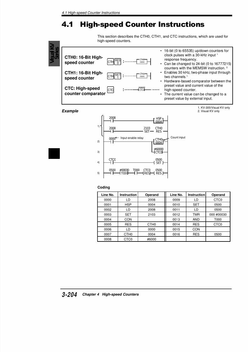
7/18/2019 Keyence Programming
http://slidepdf.com/reader/full/keyence-programming 228/392
4
0000
CTH0RES
0500SET
2103SET
CTC0
RES
2008
0500
RES
CTC0
0500 T000
#60000CTC0
#00030
T000
CTH00004
1)
2)
3)
4)
5)
Input-enable relay Count input
Coding
Line No. Instruction Operand Line No. Instructi
0000 LD 2008 0009 LD
0001 HSP 0004 0010 SET
0002 LD 2008 0011 LD0003 SET 2103 0012 TMR
4.1 H
Operands
CTH0: 00042100 to 2102
CTH1: 000505002200 to 2202
CTC0 to 3: Preset value
#00001 to #65535
Key operation
Description
1) Initializes the setting when power is turned on.• The HSP instruction sets the input time constan• The current value of CTH0 is reset as soon as
SET1
RES0
CTC
CTH
Operand
Clock input
Preset
value
ENTR-SRCH
ENT
R-SRCH
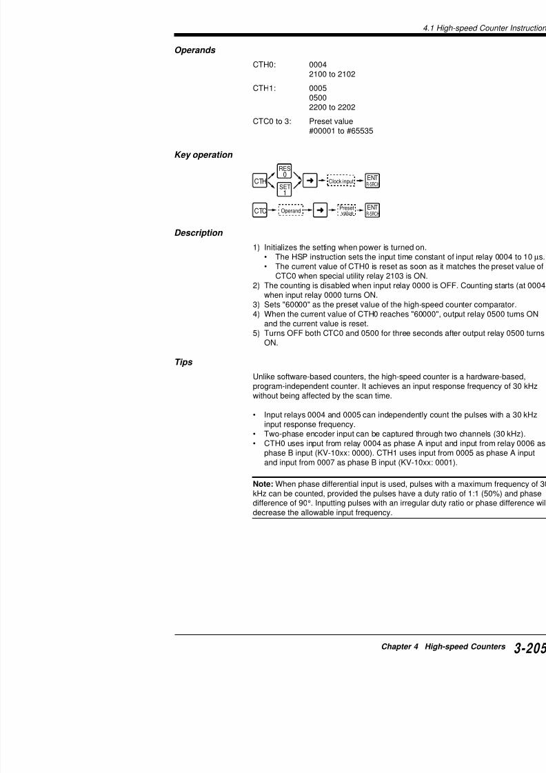
7/18/2019 Keyence Programming
http://slidepdf.com/reader/full/keyence-programming 229/392
CTC0 when special utility relay 2103 is ON.2) The counting is disabled when input relay 0000 is
when input relay 0000 turns ON.3) Sets "60000" as the preset value of the high-speed4) When the current value of CTH0 reaches "60000",
and the current value is reset.5) Turns OFF both CTC0 and 0500 for three seconds
ON.
Tips
Unlike software-based counters, the high-speed counprogram-independent counter. It achieves an input reswithout being affected by the scan time.
• Input relays 0004 and 0005 can independently couinput response frequency.
• Two-phase encoder input can be captured through• CTH0 uses input from relay 0004 as phase A inpu
phase B input (KV-10xx: 0000). CTH1 uses input f
and input from 0007 as phase B input (KV-10xx: 00
4.2 Outline of High-speed Counters
VisualKV
S
eries
4.2 Outline of High-speed Counters
This section describes the outline and specifications for high-spehigh-speed counter comparators featured with the Visual KV Ser
4.2.1 High-speed Counters and High-speed Counter
torsThe high-speed counter is a hardware-based counter that can copulses that cannot be counted by counters written in main routine(Pulses with a maximum frequency of 30 kHz can be counted.). *High-speed counter comparators are hardware-based comparatotheir preset value with the current value of one of the a high-speeBoth counters and comparators perform processing with hardwasoftware programs, enabling high-speed performance independe
Structure of high-speed counters and high-speed counter com
The Visual KV PLC has two high-speed counters, each equippedspeed counter comparators and dedicated internal clocks.
Block diagram of high-speed counters

7/18/2019 Keyence Programming
http://slidepdf.com/reader/full/keyence-programming 230/392
4
1. With the KV-10xx, the external input relay for CTH0 is 0004 (p
(phase B), and for CTH1 is 0005 (phase A)/0001 (phase B).2 With th KV 10 th t i t l f CTH0 i 0002
CTC2
CTH1
CTC3
DM1932, DM1933(INT2)DM1934, DM1935(INT3)
2
ININ
2200 (1.0 µs)2201 (10.0 µs)
2202 (100.0µs)
0500
0005/0007
CTC0
CTH0
CTC1
DM1928, DM1929(INT0)DM1930, DM1931(INT1)
2
ININ
2100 (1.0 µs)2101 (10.0 µs)2102 (100.0 µs)
0004/0006
0005(0007)
0004(0006)
0008 (RESET) 2.
0009 (RESET) 2.
Phase APhase B
Internal clocks*
External input
16-bit high-speedcounter
high-speedcountercomparator
high-speedcountercomparator
Input capture device S
C
Input capture deviceInternal clocks*
External input
16-bit high-speedcounter
high-speedcountercomparator
high-speedcountercomparator
S
C
Phase APhase B
Internal connectionfor external clock
4.2 O
List of special utility relays for high-speed coun
* Read-only relay.
yaleR.oN
noitcnuF
*0012 1(0HTCrofylnodesukcolclanretnI µ )s
*1012 01(0HTCrofylnodesukcolclanretnI µ )s
*2012 001(0HTCrofylnodesukcolclanretnI µ )s
3012 snrut0CTCrotarapmocnehw0HTCsraelcyllacitamotuA
4012 otarapmocnehw0050morftuptuotceridselbane / selbasiD
.NOsnrut
5012 CTCrotarapmocnehw0050morftuptuotceridFFOsnruT
6012 0CTCrotarapmocnehw0050morftuptuotceridNOsnruT
7012 cemithcae0050morftuptuofosutatsFFO / NOsesreveR
.NOsnrut0CTC
8012 otarapmocnehw0050morftuptuotceridselbane / selbasiD
.NOsnrut
9012 CTCrotarapmocnehw0050morftuptuotceridFFOsnruT
0112 CTCrotarapmocnehw0050morftuptuotceridNOsnruT
1112 cemithcae0050morftuptuofosutatsFFO / NOsesreveR
.NOsnrut1CTC
2112 snrut1CTCrotarapmocnehw0HTCsraelcyllacitamotuA
3112 .0HTCrofedomnoitacilpitlumstceleSO / FFO2x:FFO / NO)eslup1(noitacilpitlumoN:FFO / FFO
seslup2:NO / NO4112
noitacilpitluM noitacilpitlumoN

7/18/2019 Keyence Programming
http://slidepdf.com/reader/full/keyence-programming 231/392
List of special utility relays for high-speed coun
noitacilpitluMedom
noitacilpitlumoN)eslup1(
2x
3112 FFO NO
4112 FFO FFO
yaleR.oN
noitcnuF
*0022 1(1HTCrofylnodesukcolclanretnI µ )s
*1022 01(1HTCrofylnodesukcolclanretnI µ )s
*2022 001(1HTCrofylnodesukcolclanretnI µ )s
3022 snrut2CTCrotarapmocnehw1HTCsraelcyllacitamotuA
4022 otarapmocnehw1050morftuptuotceridselbane / selbasiD
.NOsnrut
5022 CTCrotarapmocnehw1050morftuptuotceridFFOsnruT
6022 2CTCrotarapmocnehw1050morftuptuotceridNOsnruT
7022 cemithcae1050morftuptuofosutatsFFO / NOsesreveR
.NOsnrut2CTC
8022 otarapmocnehw1050morftuptuotceridselbane / selbasiD
.NOsnrut
9022 CTCrotarapmocnehw1050morftuptuotceridFFOsnruT
0122 3CTCrotarapmocnehw1050morftuptuotceridNOsnruT
4.2 Outline of High-speed Counters
VisualKV
Series
Other special utility relays
Data memory
yaleR.oN
noitcnuF
0042 langislanretxeybeulavteserpot0HTCfoeulavtnerrucsegnahCegdegnillaftA:NO / FFOegdegnisirtA:FFO / NOdesutoN:FFO / FFO1042
6042 oN:FFOseY:NO.retnuocgnirsa0HTCsteS
7042 .0HTCrofdesusiedomnoitacilpitlumonnehwtupniBesahpserongI
pniBesahpesU:FFO.putnuocsyawladnatupniBesahperongI:NO
8042 langislanretxeybeulavteserpot1HTCfoeulavtnerrucsegnahC egdegnillaftA:NO / FFOegdegnisirtA:FFO / NOdesutoN:FFO / FFO9042
4142 oN:FFOseY:NO.retnuocgnirsa1HTCsteS
5142 .1HTCrofdesusiedomnoitacilpitlumonnehwtupniBesahpserongI
niBesahpesU:FFO.putnuocsyawladnatupniBesahperongI:NO
.oNMD noitpircseD
1091MD / 0091MD ro-hgih / stibredro-wol(0HTCtib-42foeulavtnerruC
3091MD / 2091MD ro-hgih / stibredro-wol(1HTCtib-42foeulavtnerruC
5091MD / 4091MD ro-hgih / stibredro-wol(0CTCtib-42foeulavtnerruC
7091MD / 6091MD ro-hgih / stibredro-wol(1CTCtib-42foeulavtnerruC
9091MD / 8091MD ro-hgih / stibredro-wol(2CTCtib-42foeulavtnerruC
1191MD / 0191MD ro-hgih / stibredro-wol(3CTCtib-42foeulavtnerruC
3191MD / 2191MD ro-hgih / stibredro-wol(0HTCtib-42foeulavtnerruC
5191MD/4191MD ro-hgih/stibredro-wol(1HTCtib-42foeulavtnerruC
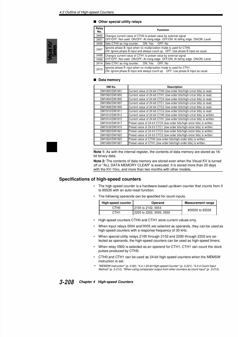
7/18/2019 Keyence Programming
http://slidepdf.com/reader/full/keyence-programming 232/392
4Note 1: As with the internal register, the contents of data memorbit binary data.
Note 2: The contents of data memory are stored even when the
off or "ALL DATA MEMORY CLEAR" is executed. It is stored mowith the KV-10xx, and more than two months with other models.
Specifications of high-speed counters
• The high-speed counter is a hardware-based up/down counteto 65535 with an auto-reset function.
• The following operands can be specified for count inputs.
5191MD / 4191MD rohgih / stibredrowol(1HTCtib42foeulavtnerruC
7191MD / 6191MD dro-hgih / stibredro-wol(0CTCtib-42foeulavteserP
9191MD / 8191MD dro-hgih / stibredro-wol(1CTCtib-42foeulavteserP
1291MD / 0291MD dro-hgih / stibredro-wol(2CTCtib-42foeulavteserP
3291MD / 2291MD dro-hgih / stibredro-wol(3CTCtib-42foeulavteserP
5291MD / 4291MD stibredro-hgih / stibredro-wol(0HTCfoeulavteserP
7291MD / 6291MD stibredro-hgih / stibredro-wol(1HTCfoeulavteserP
retnuocdeeps-hgiH dnarepO saeM
4.2 O
Note 1: CTH instructions cannot be duplicated in a prcounters, CTH0 and CTH1, can be used in one progra
Note 2: The operands for a high-speed counter cannoexecution.
Note 3: When using a high-speed counter with externstant must be set to 10 µs with the HSP instruction or (Pulses with a maximum frequency of 30 kHz can be c
Note 4: When using input 0004 as an operand, use inphase B input. Therefore, do not use input 0006 (KV-1high-speed counter.
Note 5: When selecting no multiplication mode, and y0006 (KV-10xx: 0000) as phase B input, turn ON spec
Note 6: When using input 0005 as an operand, use inphase B input. Therefore, do not use input 0007 (KV-1high-speed counter.
Note 7: When selecting no multiplication mode, and y0007 (KV-10xx: 0001) as phase B input, turn ON spec
Note 8: When using the high-speed counter internal csingle-phase input is available. In this case, external iCTH1 can be used as normal input relays.
Note 9: When using phase differential input, pulses wkHz can be counted, provided the pulses have a duty
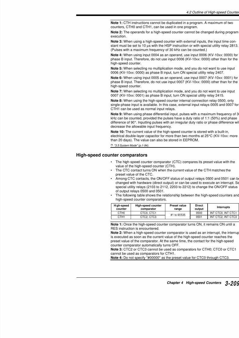
7/18/2019 Keyence Programming
http://slidepdf.com/reader/full/keyence-programming 233/392
difference of 90°. Inputting pulses with an irregular dudecrease the allowable input frequency.
Note 10: The current value of the high-speed counter electrical double-layer capacitor for more than two mothan 20 days). The value can also be stored in EEPRO
"3.5 System Mode" (p.1-94).
High-speed counter comparators
• The high-speed counter comparator (CTC) compa
value of the high-speed counter (CTH).• The CTC contact turns ON when the current value
preset value of the CTC.• Among CTC contacts, the ON/OFF status of outpu
changed with hardware (direct output) or can be usspecial utility relays (2103 to 2112, 2203 to 2212) tof output relays 0500 and 0501.
• The following table shows the relationship betweenhigh-speed counter comparators.
deeps-hgiH retnuocdeeps-hgiH eulavteserP
4.2 Outline of High-speed Counters
VisualKV
Series
4.2.2 Internal Clock for High-speed Counters• Each high-speed counter (CTH) is equipped with a dedicated• To use the internal clock, specify the appropriate relay No. as
CTH instruction.• The internal clock or external pulses cannot be changed durin
tion.• Each clock has the following count period:
High-speed counter internal clock error• Absolute error: ± 200 ppm• Temperature coefficient: 00
• Relative error between CTH0 and CTH1: ± 0
retnuocdeeps-hgiH 0HTC 1HTC
.oNyaleR
0012 0022
1012 1022
2012 2022

7/18/2019 Keyence Programming
http://slidepdf.com/reader/full/keyence-programming 234/392
4
4.3 Setting and Op
retnuocdeeps-hgiH eulavtnerruC
0HTC53556ot0
1HTC
4.3 Setting and Operation of HCounters
The high-speed counters and high-speed counter comspecified with special utility relays.
4.3.1 Reading the Current Value of the High
The current value of a high-speed counter is normally 65535).The range of the current value for high-speed counter
Refer to "4.4.1 24-bit High-speed Counter" (p. 3-221) when usi
4.3.2 Preset Value of the High-speed Count
The preset value of a high-speed counter comparator 65535)

7/18/2019 Keyence Programming
http://slidepdf.com/reader/full/keyence-programming 235/392
retnuocdeeps-hgiH retnuocdeeps-hgiH
rotarapmoc
0HTC 0CTC
1CTC
1HTC 2CTC
3CTC
65535).The relationship between high-speed counters and hig
is as follows:
Refer to "4.4.1 24-bit High-speed Counter" (p. 3-221) when usi
4.3.3 Comparator Output
The high-speed counter comparator provides the comturns ON outputs as soon as the comparator turns ONscan time.Comparator output is controlled by setting special utiliamong the high-speed counters, high-speed counter crelays are as follows:
4.3 Setting and Operation of High-speed Counters
VisualKV
Series
4.3.4 Count Input MethodSelect the input source for the high-speed counter.
When using an internal clock as input
Three types of internal clocks are provided: 1 µs, 10 µs, and 100Set the desired internal clock with a special utility relay.
When using external inputs as count inputs
Set special utility relays as follows:
edomnoitarepO0HTC
3112 4112 7042
noitacilpitlumoNesahp-elgnis(
)tupni
tnemegdu jnoitceridhtiWtupniBesahpnehwputnuoC(nwodtnuoc,FFOsi]7000[6000
)NOnehw
FFO FFO FFO
tnemegdu jnoitceridtuohtiWgnirongiybputnuocsyawlA(
)]7000[6000tupniBesahpFFO FFO NO
laitnereffidesahPtupni
2x NO FFO —
4x FFO NO —

7/18/2019 Keyence Programming
http://slidepdf.com/reader/full/keyence-programming 236/392
4 Operation mode
The counting method can be selected from the following when exused.
The ring counter function is available for each counting method. For more about the ring counter, refer to "4.4.4 Ring Counter Function" (p. 3-
Types of operation modes
No multiplication mode (single-phase input)
Counts up at the rising edge of phase A while phase B is OFF.Counts down at the rising edge of phase A while phase B is ON.
• With direction judgement (Special utility relay 2407: OFF)
ON(Phase A)
dohtemeslup-2 )nwodtnuoc:Besahp,putnuoc:AesahP( NO NO —
tupni)1HTC(0050 — — —
4.3 Setting and Op
Double (x2) mode: Counts up/down basebetween two-phase pphase B).
Quadruple (x4) mode: Counts up/down bbetween two-phasphase B).
7 6
0006
0004
CTH00 1 2 3 4 5 6 7 8
OFF
ON
OFF
ON
0006
0004 OFF
ON
OFF
ON
(Counter value)
(Phase A)
(Phase B)
(Phase A)
(Phase B)
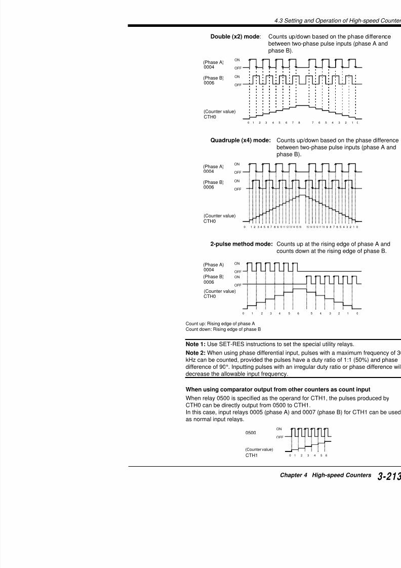
7/18/2019 Keyence Programming
http://slidepdf.com/reader/full/keyence-programming 237/392
2-pulse method mode: Counts up at the rcounts down at the
Count up: Rising edge of phase ACount down: Rising edge of phase B
Note 1: Use SET-RES instructions to set the special u
15 14 13 12 11 1
CTH00 1 2 3 4 5 6 7 8 9 10 11 12 13 14 15 16
0006
0004
CTH0
0 1 2 3 4 5 6 5 4
OFF
ON
OFF
ON
(Counter value)
(Counter value)
(Phase A)
(Phase B)
4.3 Setting and Operation of High-speed Counters
VisualKV
Series
4.3.5 Resetting the High-speed CounterReset is an operation used to set the current value of a high-speeFour types of reset operations are available: reset with input-enaexternal input, reset automatically after counting up, and reset wiinstruction.
Automatic reset after counting up
Resets the counter value as soon as the preset value matches th(CTC = CTH).This reset operation is independent of the scan time.
Note: Do not specify the same values for CTC0 and 1 (2 and 3) treset the counter with both comparators.
deeps-hgiHretnuoc
deeps-hgiHretnuoc
rotarapmoc.oNyaleR repO
0HTC
0CTC 3012 alerytilitulaicepsnehWCtnerruceht,NOdenrutCehtsehctamtisanoos
.eulav1CTC 2112
1HTC
2CTC 3022 alerytilitulaicepsnehWCtnerruceht,NOdenrutCehtsehctamtisanoos
.eulav3CTC 2122

7/18/2019 Keyence Programming
http://slidepdf.com/reader/full/keyence-programming 238/392
4
p
Reset with the RES CTH instruction
Resets the counter by writing a RES CTH instruction to the progrThis reset operation is dependent on the scan time.
* CTH is reset by the output process of the scan which execute
CTH
CTH = CTC
CTH is reset when CTH value equals CTC va
Scan
CTH
Execution of RES CTH instruction
Scan
4.3 Setting and Op
Reset with external input
Resets the counter at the instant the external reset inpThe external reset is assigned to input relay 0008 (KVinput relay 0009 (KV-10xx: 0003) for CTH1.The timing of the reset can be changed by setting relaor 2408 and 2409 (for CTH1) as follows.This reset operation is independent of the scan time.
deeps-hgiH retnuoc .oNyaleR sutatS .oNyaleR sutatS
0HTC 0042
FFO
1042
FFO iD
NO FFOeR00
FFO NOeR00
NO NOeR
K(
1HTC 8042
FFO
9042
FFO iD
NO FFOeR00
FFO NOeR00
NO NOeR
K(

7/18/2019 Keyence Programming
http://slidepdf.com/reader/full/keyence-programming 239/392
* CTH is reset at the instant the external reset input
Preset function
The current value of CTH can be changed to any desireset function of input relays 0008 (KV-10xx: 0002) (fo0003) (for CTH1) specified with special utility relays 242408 and 2409 (for CTH1). (The external reset functioWrite the desired value of the preset input into the foll
ScanExternalreset input
CTH
.oNMD
)stibredro-hgih(5291MD,)stibredro-wol(4291MD lavteserP
4.3 Setting and Operation of High-speed Counters
VisualKV
Series
4.3.6 Differences with the CTH Instruction betweeConventional and Visual KV Series
The Visual KV Series has some different high-speed counter opeconventional KV Series [KV-10/16/24/80R(W)/T(W)].
Input-enable relay
• With the conventional KV Series, the current value of the highreset when the CTH instruction is executed while the input-enHowever, the counter continues counting until the end of the sresult, when the input-enable relay starts counting again, the ready be incremented by the length of the scan time.
• With the Visual KV Series, the current value of the high-speedthe falling edge of the input-enable relay, so that the counter dcounting.
High-speed counter (CTH)
• The conventional KV Series includes high-speed counter CTHcounter. The period of the internal clock is different from that iSeries
0001 CTH00004
Count inputInput-enable relay
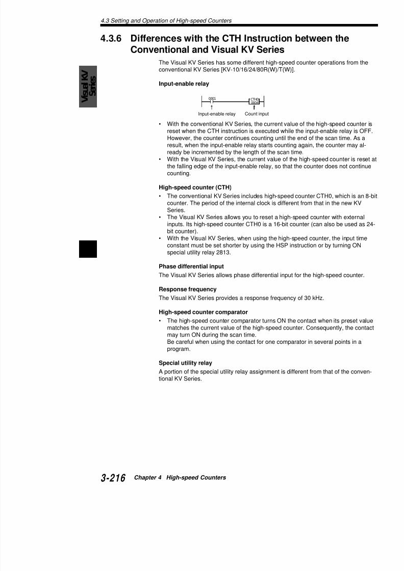
7/18/2019 Keyence Programming
http://slidepdf.com/reader/full/keyence-programming 240/392
4
Series.• The Visual KV Series allows you to reset a high-speed counte
inputs. Its high-speed counter CTH0 is a 16-bit counter (can abit counter).
• With the Visual KV Series, when using the high-speed counteconstant must be set shorter by using the HSP instruction or bspecial utility relay 2813.
Phase differential input
The Visual KV Series allows phase differential input for the high-
Response frequency
The Visual KV Series provides a response frequency of 30 kHz.
High-speed counter comparator
• The high-speed counter comparator turns ON the contact whmatches the current value of the high-speed counter. Conseqmay turn ON during the scan time.
Be careful when using the contact for one comparator in seveprogram
4.3 Setting and Op
2008
2002
0000
2214RES
2213SET
2114RES
2113SETEI
#60000
CTC0
CTH0RES
CTH00004
CTH10005
HSP0005
HSP0006
HSP0004
HSP0007
END
4.3.7 Applications of High-speed CountersComparing encoder values
Uses two encoders to input phase differential signals and 0005 and 0007. Turns ON output relay 0500 if theis greater than that of 0004 and 0006 when 0004 and
Initial sSET 21RES 2SET 22RES 2
Sets in0005,
Phase0006
Specifi
Phase 0007
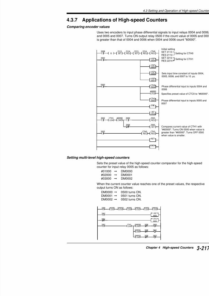
7/18/2019 Keyence Programming
http://slidepdf.com/reader/full/keyence-programming 241/392
0500RES
INT
CTC0
2002 2009
2009
2002
ENDH
RETI
0500SET
CTH0RES
CTH1RES
CTH1LDA
#60000CMP
Compa"#6000greatewhen v
Setting multi-level high-speed counters
Sets the preset value of the high-speed counter compcounter for input relay 0005 as follows:
#01000 DM0000#02000 DM0001
#03000 DM0002
4.3 Setting and Operation of High-speed Counters
VisualKV
Series
Clearing the current value of the high-speed counter
Counts pulses at input relay 0005. When the current value reach"60000", clears the current value of high-speed counter CTH1 anrelay 0502 for 3 seconds.
Line No. Instruction Operand Line No. Instructi
0000 LD 2008 0015 CTH1
0001 LDA #01000 0016 LD
0002 CON 0017 LDA
0003 STA DM0000 0018 MPS
0004 CON 0019 CMP
0005 LDA #02000 0020 ANB
0006 CON 0021 OUT
0007 STA DM0001 0022 MRD
0008 CON 0023 CMP
0009 LDA #03000 0024 ANB
0010 CON 0025 OUT
0011 STA DM0002 0026 MPP
0012 LD 2002 0027 CMP
0013 HSP 0005 0028 ANB
0014 LDB 0001 0029 OUT
Cording

7/18/2019 Keyence Programming
http://slidepdf.com/reader/full/keyence-programming 242/392
4
2203SET
CTH1RES
CTC2RES
CTC2 T001
2008
2002
#60000CTC2
CTH1
0005
2002 HSP
0005
0502 #00030 T001
Cording
Line No. Instructio
0000 LD
0001 SET
0002 CON
0003 RES
0004 LD
0005 HSP
0006 LD0007 CTH1
0008 CTC2
0009 LD
0010 OUT
0011 CON
0012 TMR
0013 CON
0015 AND
4.3 Setting and Op
Phase differential input • Inputs phase differential signals from input relays 0
pulses at CTH0.• The count value is written to DM0000.• When the current value of CTH0 reaches "60000",
output 0500, and stops counting at CTH0.• Input relay 0008 is used as an external reset.
2103
SET EI
2113
SET
2114
RES
2401
RES
CTH0
RES
0500
2008
0500
2002
CTH0
0004
2002
END
INT
CTC0
RETI
#60000
CTC0
2002 HSP
0004
HSP
0006
HSP
0008
CTH0
LDA
DM0000
STA
SET
2400
SET
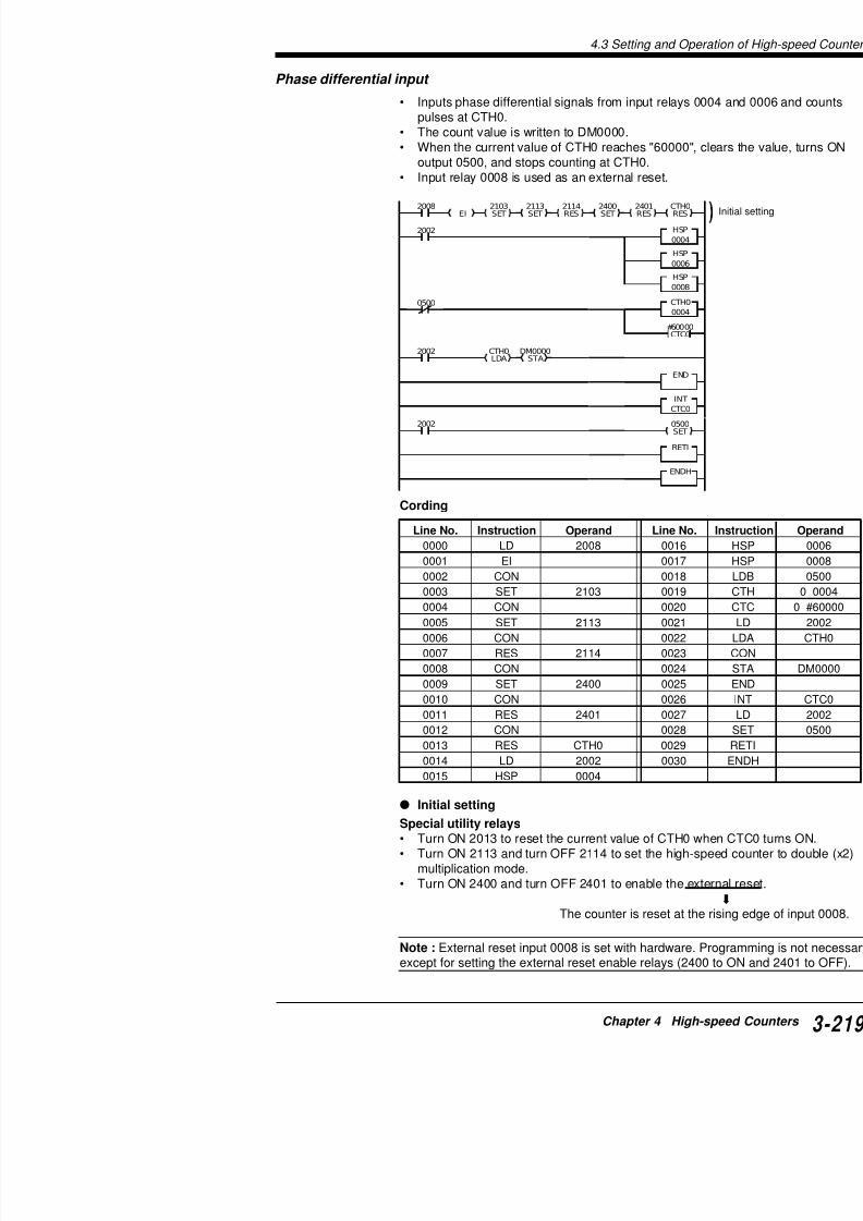
7/18/2019 Keyence Programming
http://slidepdf.com/reader/full/keyence-programming 243/392
Cording
ENDH
Line No. Instruction Operand Line No.
0000 LD 2008 0016
0001 EI 0017
0002 CON 0018
0003 SET 2103 0019
0004 CON 00200005 SET 2113 0021
0006 CON 0022
0007 RES 2114 0023
0008 CON 0024
0009 SET 2400 0025
0010 CON 0026
0011 RES 2401 0027
0012 CON 00280013 RES CTH0 0029
4.3 Setting and Operation of High-speed Counters
VisualKV
Series
Fetching counts from encoder Uses the double (x2) multiplication mode to fetch phase differentencoder.The fetched data is output as BCD data. Phase differential inputoutput: 0600 to 0615 (4 digits)
2103SET
2113SET
2114RES
CTH0RES
2400SET
2008
CTH0LDA
TM00STA
#00002DIVLDA TBCD
0600STA
2002 #00000
0000 CTH0
0004
2002 HSP0004
HSP
0006
HSP
0008
END
ENDH
Initial setting
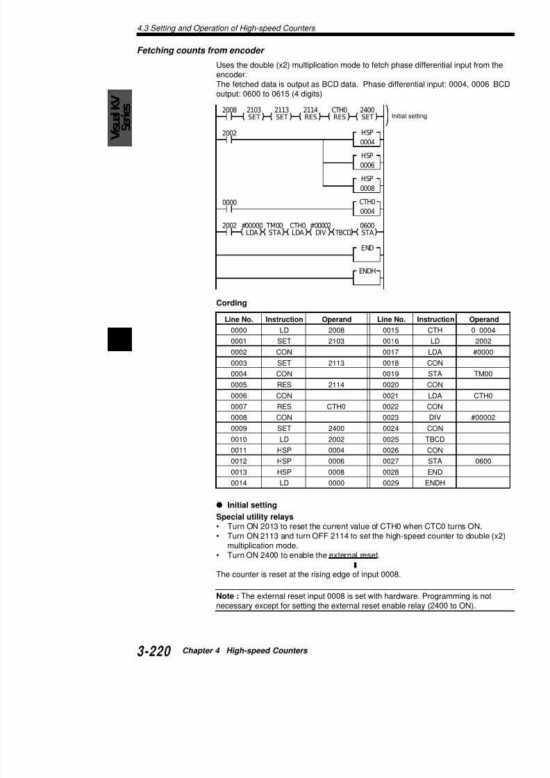
7/18/2019 Keyence Programming
http://slidepdf.com/reader/full/keyence-programming 244/392
4
Cording
Line No. Instruction Operand Line No. Instructi
0000 LD 2008 0015 CTH
0001 SET 2103 0016 LD
0002 CON 0017 LDA
0003 SET 2113 0018 CON
0004 CON 0019 STA
0005 RES 2114 0020 CON0006 CON 0021 LDA
0007 RES CTH0 0022 CON
0008 CON 0023 DIV
0009 SET 2400 0024 CON
0010 LD 2002 0025 TBCD
0011 HSP 0004 0026 CON
0012 HSP 0006 0027 STA
0013 HSP 0008 0028 END
4.4 Expanded Fun
4.4 Extended Functions of HighCounters
This section describes the 24-bit high-speed counter a
4.4.1 24-bit High-speed Counter
Normally, the high-speed counter operates with 16 bitwith 24 bits (0 to 16777215) using special utility relaysSet the 24-bit operation with the MEMSW instruction.
"MEMSW instruction" (p. 3-92)
MEMSW instruction: SW3
MEMSW instruction: SW4
.oN hctiwsfonoitcnuF NO FFO
3 retnuoctib-61 / tib-42gnitteS
0HTCrofrotarapmoc tib-42 tib-61
.oN hctiwsfonoitcnuF NO FFO
0 retnuoctib-61 / tib-42gnitteS
1HTCrofrotarapmoc tib-42 tib-61
Visual KV Series Only

7/18/2019 Keyence Programming
http://slidepdf.com/reader/full/keyence-programming 245/392
The following data memories are used for 24-bit operaRead areas
.oNMD noitpircseD .oNMD
0091MD tnerrucfostibredro-woL
eulav0HTC 6091MD
1091MD tnerrucfostibredro-hgiH
eulav0HTC 7091MD
2091MD tnerrucfostibredro-woL
eulav1HTC 8091MD
3091MD tnerrucfostibredro-hgiH
eulav1HTC 9091MD
4091MD 0CTCteserpfostibredro-woL
eulav 0191MD
5091MD teserpfostibredro-hgiH
eulav0CTC 1191MD
1HTCrofrotarapmoc
4.4 Expanded Functions of High-speed Counters
VisualKV
Series
The high-speed counter and high-speed counter comparator updthe read area of data memory each scan time.At the start of an interrupt routine, the current value is updated. Twrite area of data memory is updated with the data write operatio
"Setting the 24-bit high-speed counter comparator" (below) and "4.4.2 Changa 24-bit High-speed Counter" (p. 3-223)
Note 1: Use the SET, RES instruction pair to set the special utilitNote 2: The 16-bit/24-bit high-speed counter setting with the MEeffective when the Visual KV is in RUN mode.You must change the program to change between 16-bit and 24-
Setting the 24-bit high-speed counter comparator
To specify the preset value for the 24-bit high-speed counter comvalue into the write area DM1916 to DM1923 and execute the STtions to specify or change the preset value.
When the setting or change is properly performed, the CTC readthrough DM1911 are updated with the new values after one scan
Changing the preset value
Change the preset value for the 24-bit high-speed counter compaAccess Window, programming support software, handheld progrpanel with the following procedure.
1 Write the desired preset value into data memory
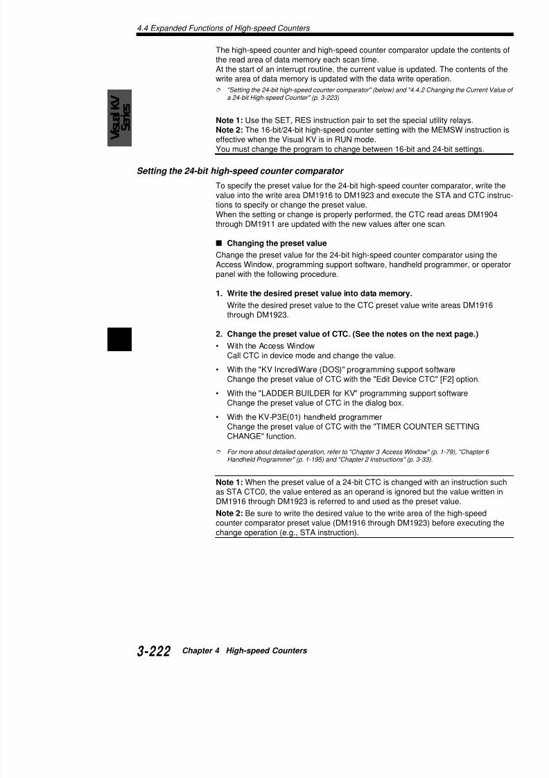
7/18/2019 Keyence Programming
http://slidepdf.com/reader/full/keyence-programming 246/392
4
1. Write the desired preset value into data memory.
Write the desired preset value to the CTC preset value write athrough DM1923.
2. Change the preset value of CTC. (See the notes on the ne
• With the Access WindowCall CTC in device mode and change the value.
• With the "KV IncrediWare (DOS)" programming support softwChange the preset value of CTC with the "Edit Device CTC" [
• With the "LADDER BUILDER for KV" programming support sChange the preset value of CTC in the dialog box.
• With the KV-P3E(01) handheld programmerChange the preset value of CTC with the "TIMER COUNTERCHANGE" function.
For more about detailed operation, refer to "Chapter 3 Access Window" (p. 1Handheld Programmer" (p. 1-195) and "Chapter 2 Instructions" (p. 3-33).
4.4 Expanded Fun
4.4.2 Changing the Current Value of a 24-biCounter
Change the current value of the 24-bit high-speed couprogramming support software, handheld programmefollowing procedure.
1. Write the desired current value into data memo
Write the desired current value to the CTH current through DM1915.
2. Change the current value of CTH. (See notes be
• With the Access WindowCall CTH in device mode and change the value.
• With the "KV IncrediWare (DOS)" programming suChange the preset value of CTH with the "Edit Dev
• With the "LADDER BUILDER for KV" programmingChange the preset value of CTH in the dialog box.
• With the KV-P3E(01) handheld programmerChange the preset value of CTH with the "TIMER CCHANGE" function.
For more about detailed operation, refer to "Chapter 3 Access Handheld Programmer" (p.1-195) and "Chapter 2 Instructions"
7/18/2019 Keyence Programming
http://slidepdf.com/reader/full/keyence-programming 247/392
Note 1: The current value of the high-speed counter cladder program.
Note 2: DM1900 to DM1923, the data memories for 2be used only when a 24-bit high-speed counter is spestruction.
4.4 Expanded Functions of High-speed Counters
VisualKV
Series
4.4.3 Application Example of 24-bit High-speed C(single-phase input)
The following is a ladder program using a 24-bit high-speed councounter comparator with a preset value of "1000000".
2008
0008
CTC0STA
DM1916STA
#16960LDA
DM1917STA
#00015LDA
2002 DM000STA
DM1901LDA
2002
0002
0001
2002
0003
0004
0006
0007
0005
High-order 16 bits of
high-speed counter
comparator
Low-order 16 bits of
high-speed counter
comparator
Writes prese
high-speed
comparator
High-order 16 bits of
current value of high-
speed counter
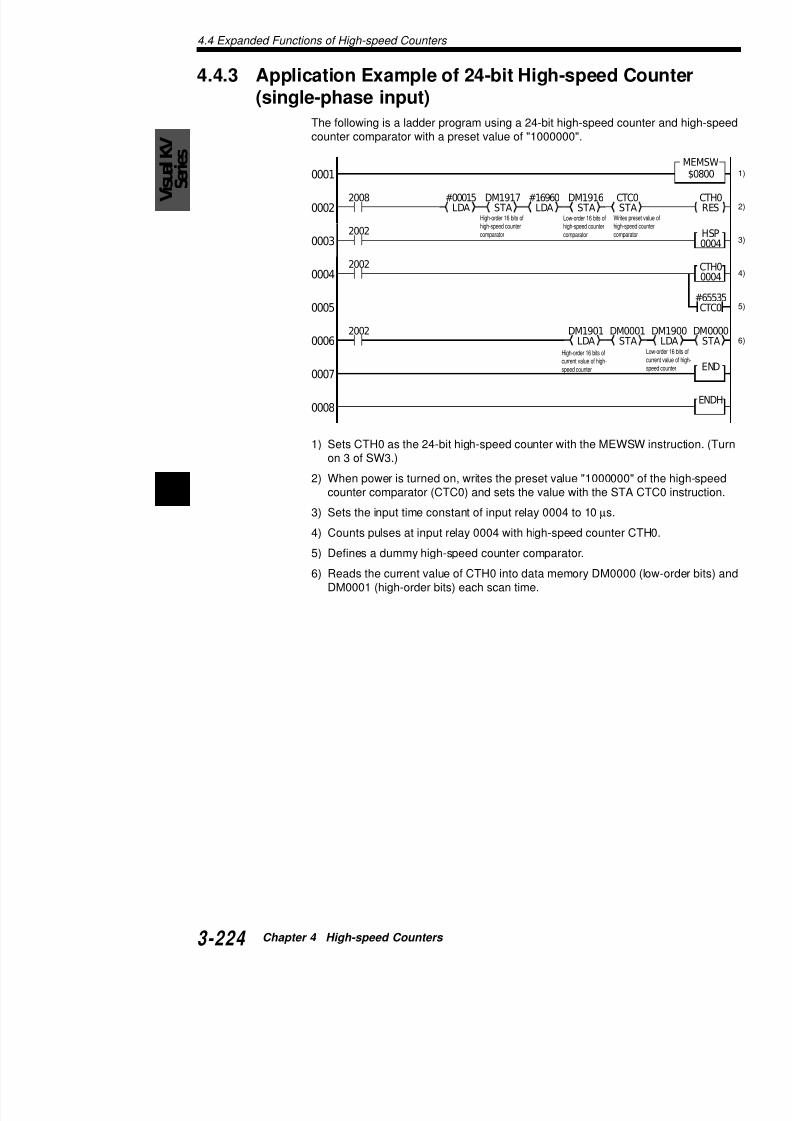
7/18/2019 Keyence Programming
http://slidepdf.com/reader/full/keyence-programming 248/392
4
1) Sets CTH0 as the 24-bit high-speed counter with the MEWSWon 3 of SW3.)
2) When power is turned on, writes the preset value "1000000" ocounter comparator (CTC0) and sets the value with the STA C
3) Sets the input time constant of input relay 0004 to 10 µs.
4) Counts pulses at input relay 0004 with high-speed counter CT
5) Defines a dummy high-speed counter comparator.6) Reads the current value of CTH0 into data memory DM0000
DM0001 (high-order bits) each scan time.
4.4 Expanded Fun
4.4.4 Ring Counter FunctionNormally, the counter reads "#65535 ($FFFF)" by couThe ring counter function is an additional function of threads "preset value - 1" when it counts down from "0"
Operation of the ring counter function
Setting procedure
• When setting the ring counter, use CTC1 for CTH0• Set the upper limit (preset value) to CTC1 or CTC3
relay 2406 (for CTH0) or 2414 (for CTH1). The ringCTC3 preset value - 1" when it counts down from "
• To use the ring counter for both counting up/down utility relay 2112 (for CTH0) or 2212 (for CTH1).
0
0 CTC1 -1
( CTC3 -1)
Not u
Normal counter
Ring counter

7/18/2019 Keyence Programming
http://slidepdf.com/reader/full/keyence-programming 249/392
Note 1: Use the SET-RES instruction pair to set the s
Note 2: The flag or the count-up interrupt for each CToperations, but is disabled in counting down operation
Example: When CTC = 100
CTC
Countup
Countdown
Turns ON.
retnuocdeeps-hgiH otarapmocretnuocdeeps-hgiH
desusi0HTCnehW CTCot"1+eulavtimilreppu"teS
desusi1HTCnehW CTCot"1+eulavtimilreppu"teS
4.4 Expanded Functions of High-speed Counters
V
isualKV
Series
0 9999
2008
0003
0005
EI2406SET
2114RES
2113SET
2002
0001
0002
#00010
2002 0004
0500 T000
Sets high-speed counter indouble (x2) multiplication mode.
Sets ringcounter.
4.4.5 Applications of Ring CountersWhen using a 16-bit high-speed counter
The following is a ladder program that uses the ring counter of a counter with the preset value of "10000".

7/18/2019 Keyence Programming
http://slidepdf.com/reader/full/keyence-programming 250/392
4
0007
0006
0010
0011
0009
T000
2002
0008
1) When the power is turned on, an EI instruction enables interruspeed counter CTH0 in double (x2) multiplication mode, CTHand the high-speed counter automatic reset function at counti
high-speed counter
4.4 Expanded Fun
0 99999
2008
0004
EI2114RES
2113SET
2002
0002
#00001
LDA
DM19
STA0003
2002
0005
0001
Sets high-speedcounter in double (x2multiplication mode.
High-orderbits of highspeed coucomparato
When using a 24-bit high-speed counter The following is a ladder program that uses the ring cocounter with the preset value of "100000".

7/18/2019 Keyence Programming
http://slidepdf.com/reader/full/keyence-programming 251/392
0013
0006
0008
0012
0007
0011
0010
#00010 T000
0500 T000
2002
0009
4.5 Special Functions Using High-speed Counters
V
isualKV
Series
4.5 Special Functions Using High-spCounters
This section describes the specified frequency pulse output functcounter function, and cam switch function.
4.5.1 Specified Frequency Pulse Output FunctionWith high-speed counter CTH1, output pulses from output relay 0frequency (Hz) specified in data memory DM1936. To activate thdesired value into DM1936 and turn ON special utility relay 2306
The internal clock of the high-speed counter is automatically set duty ratio of 1:1 are output at the preset frequency obtained with "1,000,000/2/Output frequency".
The KV performs the following operations after each scan time dfrequency pulse output function.
• Stops pulse output when special utility relay 2306 is turned O• Sets the preset value so that pulses are output at the frequen
the DM. (Pulse duty ratio: fixed to 50%)• Starts pulse output.
Visual KV Series Only

7/18/2019 Keyence Programming
http://slidepdf.com/reader/full/keyence-programming 252/392
4
OFF
ON
Pulse dutyPulse duty is the ratio of the pulse widths between ON time and Oduty of 50% means that the pulse widths between ON time and Osame, as follows.
The ratio between ON and OFF time is 1:1.
Device used for specified frequency pulse output
Special utility relays
.oNyaleR noitpircseD
6032 seY:NO.tuptuoeslupycneuqerfdeificepsesU
.NOsnrut7032yalerrorrenehwFFOdecrofsi
7032 nuftuptuoeslupycneuqerfdeificepsrofgalfrorrE
ahtrehtosi6391MDfostnetnocnehwNOsnruT
4.5 Special Functions
Setting method
• Set the desired output frequency (Hz) into DM1936to 50 kHz (16 to 50000).
• Pulses are output when special utility relay 2306 iswhen the relay is turned OFF.
• If an unacceptable frequency is specified, special uturns ON. Special utility relay 2306 is turned OFF a
Note 1: The available minimum frequency specified inNote 2: The output is stopped when a value of 15 or l
Note 3: Starts and stops of pulse output or frequency each scan.
Note 4: It takes a maximum of 200 µs from when the pulses are output.
Note 5: CTH1 and special utility relays 2200 through 2specified frequency pulse output function is used.
4.5.2 Applications of the Specified Frequen
Program using a digital trimmer
The following ladder program illustrates how to use a at a desired frequency (16 Hz to 10 kHz).Pulse output is stopped when the value of the digital tless.

7/18/2019 Keyence Programming
http://slidepdf.com/reader/full/keyence-programming 253/392
1) Sets the upper limit of the digital trimmer to "10000relay 2306 to start the specified frequency pulse ou
2) Sets the input value of the digital trimmer as the ou
3) Output relay 0500 turns ON when a setting error o
2008
0003
0005
2002
0001
2307
0002
0004
4.5 Special Functions Using High-speed Counters
V
isualKV
Series
Program for speed control
The following ladder program illustrates speed control using the spulse output function.Control is started when input relay 0000 turns ON. The operationand then stopped when input relay 0001 turns ON.By specifying the speed (Hz) in data memory DM0000, the progrspeed with a start-up speed of 16 Hz and an acceleration speed
0003
0005
#00016LDA
DM1936LDA
DM0000CMP
DM0000STA
DM1936CMP
0001
2010
2307
0002
0006
0004
1000
DIFU
0000 1000
1001DIFU
0001 1001
1101
1100
T000
0007
0008
0009
2009
2011
T000
2306RES
#00016
LDA
DM1936
STA

7/18/2019 Keyence Programming
http://slidepdf.com/reader/full/keyence-programming 254/392
4
1) Sets "16" as the preset speed at the rising edge of input relayspecial utility relay 2306 to start the specified frequency pulse
TM02STA
DM1936LDA
DM0000LDA
DM1936SUB
#00100CMP
2011
DM1936LDA
2011
2002
TM02
STA
DM1936
LDA
DM1936
LDA
DM0000
SUB
#00100
CMP
2011
DM1936LDA
2011
2002
0011
0013
0010
0014
0012
0015
0016
0017
4.5 Special Functions
4.5.3 Frequency Counter FunctionHigh-speed counter CTH0 is used. Write the interval (ment into data memory DM1404 and turn ON special surement result (Hz) is written into DM1405.Input relay 0004 is for pulse input (single-phase input)input) is ignored.
Devices used with the frequency counter
Special utility relays
Data memory
Operation flow
1. Set the high-speed counter with external input. Usmeasure how much time has elapsed since the lasµs. After each scan, pulses are counted within the memory. The frequency is calculated from the cou
.oNyaleR tpircseD
5032 FO,seY:NO.retnuocycneuqerfesU
.oNMD tpircseD
4041MD ycneuqerffo)sm(elcyctnemerusaeM
5041MD qerffo)zH(tnuocycneuqerffotluseR

7/18/2019 Keyence Programming
http://slidepdf.com/reader/full/keyence-programming 255/392
memory.
2. When the time specified with DM1404 elapses fromcurrent value of CTH0 is fetched and divided by thThe frequency is obtained with the following calcul
Frequency (Hz) = (100,000 x Pulse count)
3. The calculation result (Hz) is written into DM1405.
Setting method
1. Specify the counting period for the frequency counmeasurement [Unit: ms]) in data memory DM1404
2. The preset value must be greater than the scan timthe scan time is specified, the frequency is measur
Note 1: To use the frequency counter function set the
4.5 Special Functions Using High-speed Counters
V
isualKV
Series
4.5.4 Applications of Frequency CountersProgram for basic operation of the frequency counter
Stores the frequency of pulses at input relay 0004 to DM0000 evms). (Unit: Hz)
1) Sets the counting period to "1000 ms (1 second)" and turns Orelay 2305 to start the frequency counter function.
2) Sets the input time constant for input relay 0004 to 10 µs.3) Stores the measured frequency (Hz) into data memory DM00
Program for synchronous control
The following ladder program illustrates synchronous control usin
t d l t t f ti
00012008
0003
2002
2002
0004
0002
#01000LDA
0005

7/18/2019 Keyence Programming
http://slidepdf.com/reader/full/keyence-programming 256/392
4
counter and pulse output functions.Measures the frequency of pulses at input relay 0004 every 100 pulses of the same frequency from output relay 0501.
00012008
0003
2002
2002
0004
0002
#00100LDA
DM1404STA
2307
0005
0006
D
4.5 Special Functions
4.5.5 Cam Switch FunctionThe cam switch function has two modes: cam switch moperation; and multi-step comparator mode, which coDM1401 with multiple values.
Devices used with the cam switch function
Special utility relays
The preset value in the data memory is registered at trelay. When the preset value is changed, turn OFF spand then turn it ON again to register the new value.
Timing diagram of cam switch function
: Operation with the ladder program
.oNyaleR noitpircseD
4132 yalertratS
5132 yalerrorrE
5172 yalernoitarepo-nI
2715
2314
Executed
Start relay
In-operationrelay
Cam switchfunction
Stopped Stopped
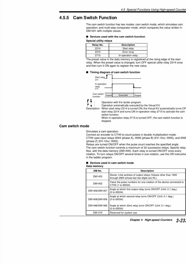
7/18/2019 Keyence Programming
http://slidepdf.com/reader/full/keyence-programming 257/392
: Operation with the ladder program.: Operation automatically executed by the V
Description: When start relay 2314 is turned ON, the Visstart relay 2314 and turns ON in-operation switch function.When in-operation relay 2715 is turned OFstopped.
Cam switch mode
Simulates a cam operation.Connect an encoder to CTH0 to count pulses in doubCTH0 uses input relays 0004 (phase A), 0006 (phase (phase Z) (KV-10xx: 0002).Relays are turned ON/OFF when the pulse count reacThe cam switch function controls a maximum of 32 suNos. with the data memory (DM1400). Each relay is turotation. To turn relays ON/OFF several times in one rin the ladder program.
4.5 Special Functions Using High-speed Counters
V
isualKV
Series
Multi-step comparator modeEven a single phase incoder can be used by changing a part of tfunction.To activate the multi-step comparator mode, write the value to bedata memory DM1401 to replace the CTH0 value. This value dettion. If 360 is written in DM1401, and 60 is written in DM1406, theON at 60/360 i.e. 60°.
Devices used in multi-step comparator mode
Data memory
Setting method
In cam switch mode
.oNMD noitpircseD
0041MD htoseulaV(syalertuptuofosserddalaitiniserotS
.).00erastigidowttsalesohw0092hguorht
1041MD )43556ot0(derapmoceboteulaV
2041MD domrotarapmocegats-itlumesuot"53556"retnE
7041MD / 6041MD O / NOsnrutyalertuptuotsrifhcihwtaeulavteserP9041MD / 8041MD
•••
9641MD / 8641MD
FFO / NOsnrutyalerdnoceshcihwtaeulavteserP•••
0(FFO / NOsnrutyalerdn23hcihwtaeulavteserP
0741MD esumetsysrofdevreseR

7/18/2019 Keyence Programming
http://slidepdf.com/reader/full/keyence-programming 258/392
4
In cam switch mode1. Write the initial number of output relays to be used into DM14
Be sure to write the initial relay number of each channel.Example 0500, 0600: Acceptable, 0501, 0610: Unaccep
2. Write the number of pulses in two pulse-periods of the encodeCTH0 into DM1402. (Twice the number of pulses for one rota
3. Specify the angle at which the first relay turns ON (Unit: 0.1 d
DM1406. Use units of 0.1 deg. to specify the preset angle for mode. (Write the value of [Desired angle x 10] into data memo
4. Specify the angle at which the first relay turns OFF (Unit: 0.1 DM1407.
5. Specify the angle at which the second relay turns ON (Unit: 0DM1408.
6. Specify the angle at which the second relay turns OFF (Unit: DM1409.
4.5 Special Functions
5. Specify the preset value at which the second relay6. Specify the preset value at which the second relay
7. Repeat steps 3 through 6 as many times as the nurelays max.).
8. Turn ON special utility relay 2314.This relay automatically turns OFF when the cam s
9. Turn OFF special utility relay 2715 to stop the ope
Note 1: When the cam switch function is used, 32 relafied with DM1400 is occupied for the function regardlenot. As a result, these relays cannot be used for any o
Note 2: To use the cam switch mode, set the input timHSP instruction or the special utility relay. (A maximummeasured.)
Note 3: When any improper value is set in data memand special utility relay 2315 turns ON.
Note 4: CTH0 and the frequency counter function caswitch function is being used.
Note 5: The cam switch function cannot be used wheprogram.
Note 6: Special utility relays concerning CHT0, CTC0function cannot be used.
Note 7: The scan time is extended by a maximum of function is activated.
N t 8 Th i ti l f th it h f

7/18/2019 Keyence Programming
http://slidepdf.com/reader/full/keyence-programming 259/392
Note 8: The in-operation relay of the cam switch funcwhen the mode is changed or the power is turned OF
Note 9: Use the END instruction to change relays or
Note 10: When the encoder is ON in cam switch modcount may be shifted for the time between the start-up
Note 11: The encoder count is stopped in cam switchOFF. (While the Visual KV is ON, the count is continu
Note 12: When a value of 360° or more is specified aswitch function, the value is converted into one within the control.
Example: When 500° is specified, it is converted to 14
4.5 Special Functions Using High-speed Counters
V
isualKV
Series
4.5.6 Application of the Cam Switch (Cam Switch The following ladder program illustrates the basic setting of the cConnect the encoder with a resolution of 360 pulses.Use output relays 0600 through 0603.Output relay 0600: Turns ON within the range 30° to 90°Output relay 0601: Turns ON within the range 45° to 80°Output relay 0602: Turns ON within the range 70° to 150°Output relay 0603: Turns ON within the range 120° to 270°
##00600LDA
DM1400STA
2008
2002
0001
0000
0001
0002
0005
0007
0003
0004
0008
0006
#
D
#01500DW
DM1411
#00700DW
DM1410
#00800DW
DM1409
#00450DW
DM1408
#00900DW
DM1407
#00300DW
DM1406
1000
1001DIFU
1000DIFU
1001
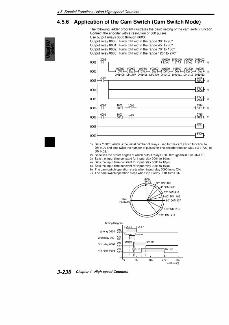
7/18/2019 Keyence Programming
http://slidepdf.com/reader/full/keyence-programming 260/392
4 1) Sets "0600", which is the initial number of relays used for the cam swDM1400 and sets twice the number of pulses for one encoder rotatioDM1402.
2) Specifies the preset angles at which output relays 0600 through 0603) Sets the input time constant for input relay 0004 to 10 µs.
4) Sets the input time constant for input relay 0006 to 10 µs.5) Sets the input time constant for input relay 0008 to 10 µs.6) The cam switch operation starts when input relay 0000 turns ON.7) The cam switch operation stops when input relay 0001 turns ON.
0008
0009
3600(360°)
30° DM1406
45° DM1408
70° DM1410
80° DM1409
4.6
4.6 Direct Clock Pulse OutputThis section describes the outline and setting method
4.6.1 Outline of Direct Clock Pulse Output
Using the high-speed counter (CTH) and high-speed cKV PLC can output clock pulses directly through outp
without any delays caused by the scan time.
The period (frequency) and width of the pulses are deinternal clock used for the high-speed counter (CTH) aparator (CTC).
The period of the clock pulse (frequency) can be chanthe following ranges.
tuptuO kcolclanretnI foegnaR
0050
0.1(0012 µ )s 02 µ t)zHk05(s
0.01(1012 µ )s 02 µ t)zHk05(s
0.001(2012 µ )s 002 µ t)zHk5(s
1050
0.1(0022 µ )s 02 µ t)zHk05(s
0.01(1022 µ )s 02 µ t)zHk05(s
0.001(2022 µ )s 002 µ t)zHk5(s

7/18/2019 Keyence Programming
http://slidepdf.com/reader/full/keyence-programming 261/392
Pulses of the internal clock are counted with the high-the number of current pulses reaches the preset valuecomparator (CTC), the ON/OFF status of output relayto output direct clock pulses.
Count value
Note 1: The operation of output relays 0500 and 0501special utility relays.
Note 2: For more about setting special utility relays, rspeed Counters" on page 3-206.
N t 3 Th ON/OFF t t h th di t l k
CTC
ONON
4.6 Direct Clock Pulse Output
V
isualKV
Series
4.6.2 Pulse Output Setting with the High-speed CoComparator
Changing the pulse period and width
By using two high-speed counter comparators, you can change owhile keeping the pulse period constant, or change only the pulsekeeping the pulse width constant.The following examples illustrate how the pulse width and period
with the high-speed counter comparator.
ON-OFF ratio of 1:1
Pulse width (µs) = CTC0 preset value x internal clock (µs)
Pulse period (µs) = CTC0 preset value x 2 x internal clock (µs
Use the following calculation to obtain the pulse period from the f
OFF
ON
Pulse period
ON/OFF status is set by special utility
Pulse width
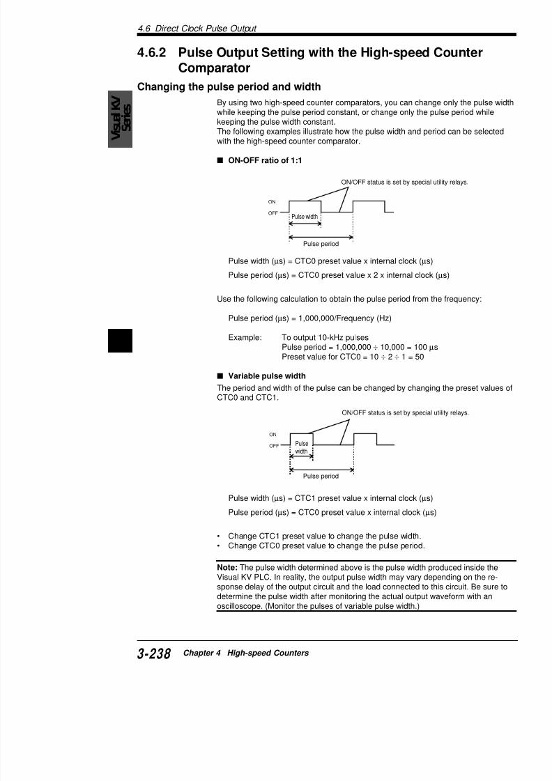
7/18/2019 Keyence Programming
http://slidepdf.com/reader/full/keyence-programming 262/392
4
Pulse period (µs) = 1,000,000/Frequency (Hz)
Example: To output 10-kHz pulsesPulse period = 1,000,000 ÷ 10,000 = 100 µsPreset value for CTC0 = 10 ÷ 2 ÷ 1 = 50
Variable pulse width
The period and width of the pulse can be changed by changing tCTC0 and CTC1.
OFF
ON
Pulse period
ON/OFF status is set by special utilit
Pulsewidth
4.6
Calculating the pulse period and comparator preset vaThe Visual KV PLC can output a maximum clock pulsUse the following calculations to obtain the pulse periohigh-speed counter comparator used to output the clo
Pulse period
Pulse period (µs) = 1,000,000 ÷ Frequency (Hz)
CTC preset value for pulses with 1:1 ON/OFF raCTC preset value = Pulse period (µs) ÷ Internal clock
CTC preset value for pulses with variable pulse
CTC preset value for pulse width = Pulse width (µs) ÷CTC preset value for pulse period = Pulse period (µs)
OFF
ON
Pulsewidth
Pulse period
OFF
ON
Pulsewidth
Pulse period
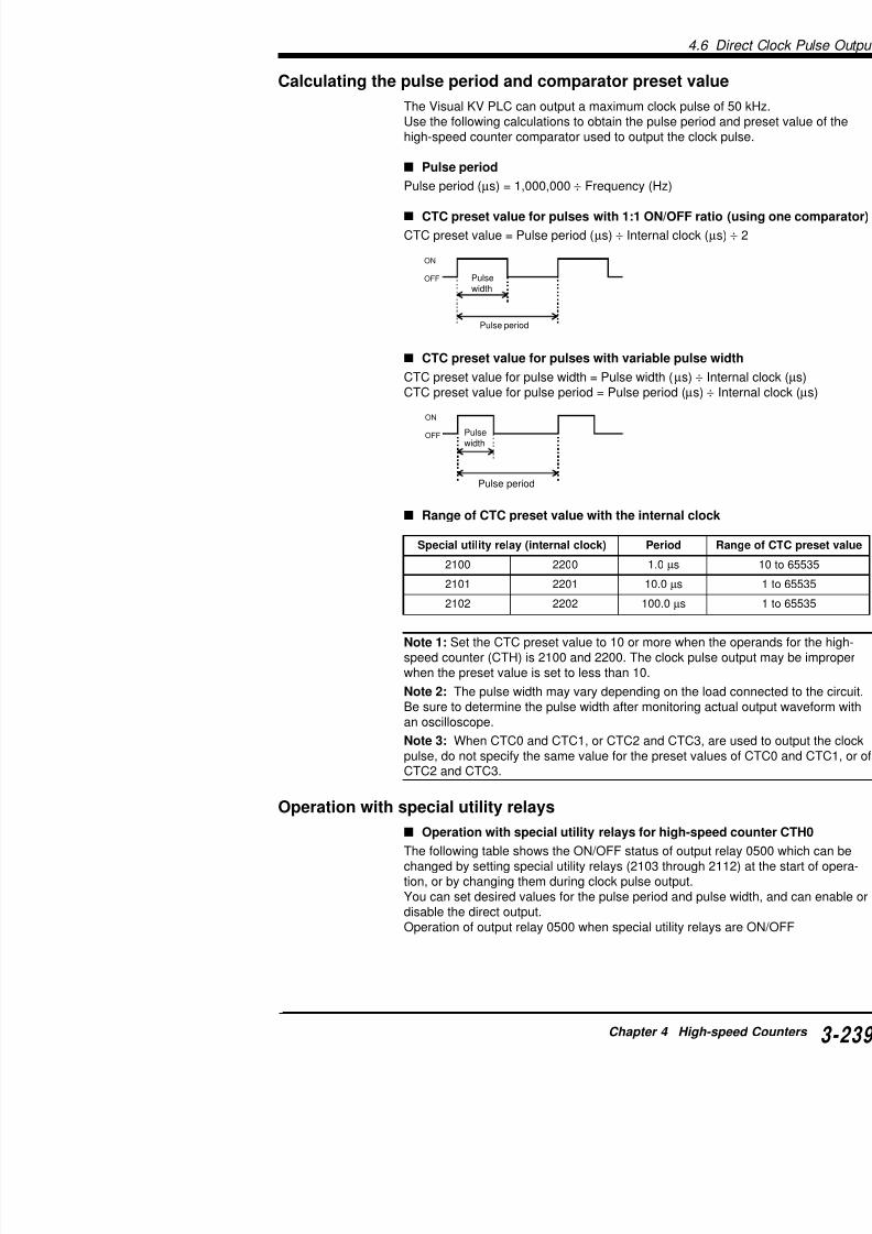
7/18/2019 Keyence Programming
http://slidepdf.com/reader/full/keyence-programming 263/392
Range of CTC preset value with the internal clo
Note 1: Set the CTC preset value to 10 or more whenspeed counter (CTH) is 2100 and 2200. The clock pulwhen the preset value is set to less than 10.
Note 2: The pulse width may vary depending on the Be sure to determine the pulse width after monitoring an oscilloscope.
Note 3: When CTC0 and CTC1, or CTC2 and CTC3,l d t if th m l f th t
)kcolclanretni(yalerytilitulaicepS doireP
0012 0022 0.1 µs
1012 1022 0.01 µs
2012 2022 0.001 µs
4.6 Direct Clock Pulse Output
V
isualKV
Series
Setting the special utility relayTh i l ili l b h l k l S
deeps-hgiHretnuoc
rotarapmoc
laicepSytilitu
yaler
erruc(0HTCnehwnoitarepO
avteserp(CTCsehcaer
0CTC
3012 foeulavtnerrucsraelcyllacitamotuA
0HTC O
4012 .0050folortnocselbane / selbasiD O
D
5012 .0050hguorhttuptuotceridFFOsnruT O
6012 .0050hguorhttuptuotceridNOsnruT O
7012 .0050fosutatsFFO / NOsesreveR O
1CTC
8012 .0050folortnocselbane / selbasiD O
D
9012 .0050hguorhttuptuotceridFFOsnruT O
112 .0050hguorhttuptuotceridNOsnruT O
1112 .0050fosutatsFFO / NOsesreveR O
2112 foeulavtnerrucsraelcyllacitamotuA
0HTC O

7/18/2019 Keyence Programming
http://slidepdf.com/reader/full/keyence-programming 264/392
4
The special utility relay must be set to output the clock pulse. Setfollowing manner.• Only one relay for each group can be turned ON from relays 2
and 2108 through 2111.• Use the SET-RES pair or STA instruction to turn relays 2103
OFF.• Turning OFF relays 2104 or 2108 enables control of output re
• To change the pulse width, be sure to first turn ON relays 210matically clear the current value of CTH0. You cannot changeunless you turn ON relays 2103 or 2112.
• Turning ON/OFF relay 2105 stops/outputs the clock pulse.
Note: If two or more relays of special utility relays 2104 through 2through 2111 are turned ON, priority is given to the relay with the
Operation of output 0500 by setting special utility relays
4.6
Operation with special utility relays for high-sp
The following table shows the ON/OFF status of outpuchanged by setting special utility relays (2203 throughtion, or by changing them during clock pulse output.You can set desired values for the pulse period and pdisable the direct output.Operation of output relay 0501 when special utility rela
S tti th i l tilit l
deeps-hgiHretnuoc
rotarapmoc
laicepS
yalerytilitu
CnehwnoitarepO
CTCsehcaer
2CTC
3022 tnerrucsraelcyllacitamotuA
1HTCfo
4022 folortnocselbane / selbasiD
5022 rhttuptuotceridFFOsnruT
.1050
6022 orhttuptuotceridNOsnruT
.1050
7022 osutatsFFO / NOsesreveR
3CTC
8022 folortnocselbane / selbasiD
9022 rhttuptuotceridFFOsnruT
.1050
0122 orhttuptuotceridNOsnruT
.1050
1122 osutatsFFO / NOsesreveR
2122 tnerrucsraelcyllacitamotuA
1HTCfo

7/18/2019 Keyence Programming
http://slidepdf.com/reader/full/keyence-programming 265/392
Setting the special utility relay
The special utility relay must be set to output the clockfollowing manner.• Only one relay for each group can be turned ON fr
and 2208 through 2211.• Use the SET-RES pair or STA instruction to turn re
OFF.
• Turning OFF relays 2204 or 2208 enables control • To change the pulse width, be sure to first turn ON
matically clear the current value of CTH1. You canunless you turn ON relays 2203 or 2212.
• Turning ON/OFF relay 2205 stops/outputs the cloc
Note: If two or more relays of special utility relays 220through 2211 are turned ON, priority is given to the re
O ti f t t 0501 b tti i l tilit
4.7 Examples of Direct Clock Pulse Output
V
isualKV
Series
4.7 Examples of Direct Clock PulseThis section describes programming examples of the direct clock
4.7.1 Example of Outputting a Pulse with 1:1 ON/O
To output a clock pulse of 1 ms (1 kHz)-period from output relay 0500
This section describes a programming example that will output aON/OFF ratio from output relay 0500 by using the high-speed cohigh-speed counter comparator (CTC0).
Special utility relay setting
Set the special utility relay (2103 through 2112) according to the When outputting a pulse with 1:1 ON/OFF ratio, you can simplifyusing the reverse (toggle) output (2107: ON).
Internal clock and CTC0 preset value
Specify the internal clock and calculate the preset value of CTC0
.oNyaleR gnitteS
3012 NO
4012 FFO
5012 FFO
6012 FFO
7012 NO

7/18/2019 Keyence Programming
http://slidepdf.com/reader/full/keyence-programming 266/392
4CTC0 preset value = Pulse period (µs) ÷ Internal clock (µs) ÷
Obtain the preset value of CTC0 by substituting 1 ms for the pulsfor the internal clock (special utility relay 2101).In this case, the preset value of CTC0 is "50".Refer to the following table for the preset value of CTC0 with othe
ExampleCount value
yalerytilitulaicepS kcolclanretnI eulavteserp0CTC
0012 0.1 µs 005
1012 0.01 µs 05
2012 0.001 µs 5
2103SET 2104RES 2105RES 2106RES 2107SET CTH0RES20080001
4.7 Examples o
Cording
Note :When the input enable relay for the high-speed the clock pulse, the response is delayed by a maximustarts. Moreover, if the response is delayed by one scclock pulse stops but the output may remain ON.
Tips
• Use special utility relay 2105 to control (enable/disexternal inputs.
• Use the SET-RES pair or KEEP instruction to turn OFF.
• With this setting, the clock pulse is always turned Ostops.
• When either of the following programs is added to page, the clock pulse is output from 0500 only whe
When SET-RES instructions are used When KE
Line No. Instruction Operand Line No.
0000 LD 2008 0008
0001 SET 2103 0009
0002 CON 0010
0003 RES 2104 0011
0004 CON 0012
0005 RES 2105 0013
0006 CON 0014
0007 RES 2106
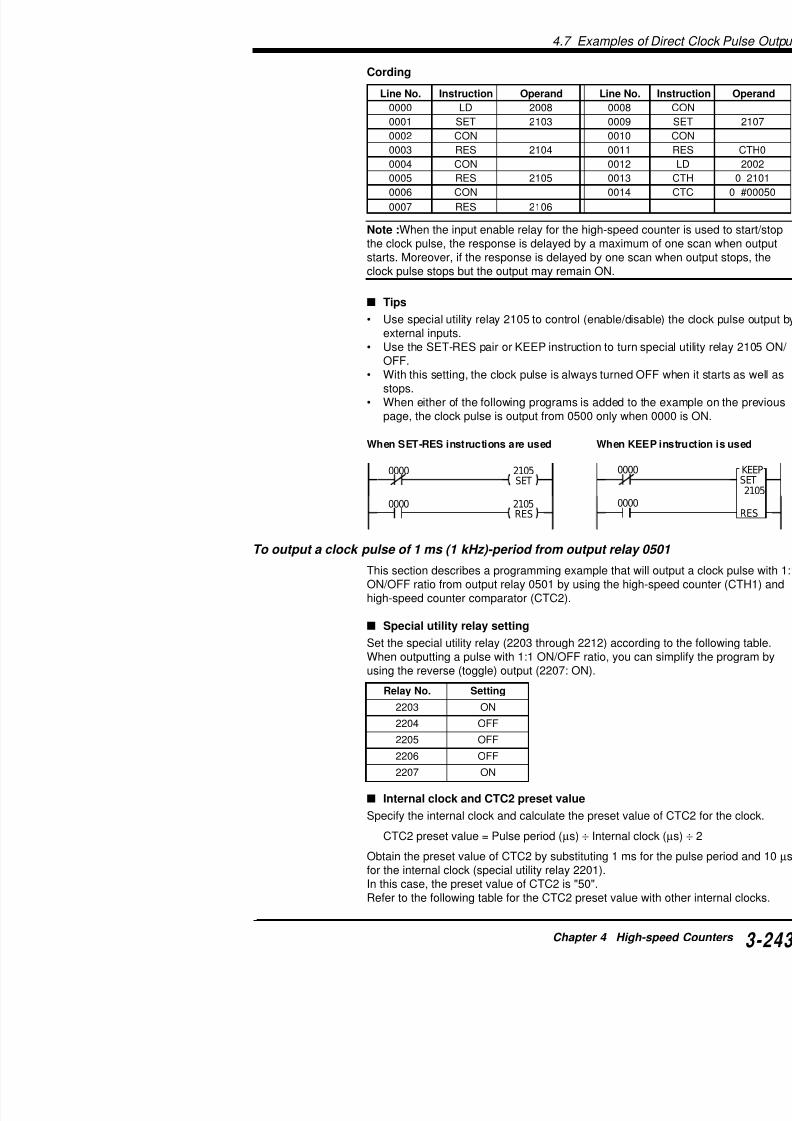
7/18/2019 Keyence Programming
http://slidepdf.com/reader/full/keyence-programming 267/392
0000
0000 2105RES
2105SET
0000
0000
To output a clock pulse of 1 ms (1 kHz)-period from output relay
This section describes a programming example that wON/OFF ratio from output relay 0501 by using the highigh-speed counter comparator (CTC2).
Special utility relay setting
Set the special utility relay (2203 through 2212) accorWhen outputting a pulse with 1:1 ON/OFF ratio, you cusing the reverse (toggle) output (2207: ON).
4.7 Examples of Direct Clock Pulse Output
V
isualKV
Series Example
Count value
• Sets the pulse output from output relay 0501 with special utility relayIn this example, turns OFF 2204 to enable direct output from 0501 areverse the output each time the CTH1 value reaches the CTC2 valu
• Turns ON 2203 to set CTH1 to be cleared when its value reaches th
With this setting, the operation which clears the CTH1 current value CTC2 preset value is repeated.
• The RES CTH1 instruction resets the CTH1 current value when opeensures that the first clock pulse is output at the proper pulse width.Turn ON the input enable relay for CTH1 all the time when CTH1 is uclock pulse.
Coding
CTC2
ON
yalerytilitulaicepS kcolclanretnI eulavteserp2CTC0022 0.1 µs 005
1022 0.01 µs 05
2022 0.001 µs 5
2203SET
2204RES
2205RES
2206RES
CTH1RES
2008
2002
#00050CTC2
CTH1
2201
0001
0002
0003
2207SET
Line No. Instruction Operand Line No. Instructi
0000 LD 2008 0008 CON0001 SET 2203 0009 SET

7/18/2019 Keyence Programming
http://slidepdf.com/reader/full/keyence-programming 268/392
4
Note :When the input enable relay for the high-speed counter is the clock pulse, the response is delayed by a maximum of one scstarts. Moreover, if the response is delayed by one scan when ouclock pulse stops but the output may remain ON.
Tips
• Use special utility relay 2205 to control (enable/disable) the c
t l i t
0002 CON 0010 CON
0003 RES 2204 0011 RES
0004 CON 0012 LD
0005 RES 2205 0013 CTH
0006 CON 0014 CTC
0007 RES 2206
4.7 Examples o
4.7.2 Example of Outputting a Pulse with VaRatio
To output a clock pulse of 500 µs (2 kHz)-period and 200 µs-widt
This section describes a programming example that wvariable ON/OFF ratio from output relay 0500 by using(CTH0) and high-speed counter comparator (CTC0 an
Special utility relay settingSet the special utility relay (2103 through 2112) accor
Internal clock and CTC0/CTC1 preset values
Specify the internal clock and calculate the preset valuclock.
CTC1 preset value = Pulse width (µs) ÷ Internal cloCTC0 preset value = Pulse period (µs) ÷ Internal c
Obtain the preset values of CTC0 and CTC1 by substwidth, 500 µs for the pulse period, and 10 µs for the in
.oNyaleR gnitteS .oNyaleR
3012 NO 8012
4012 FFO 9012
5012 FFO 0112
6012 NO 1112
7012 FFO 2112
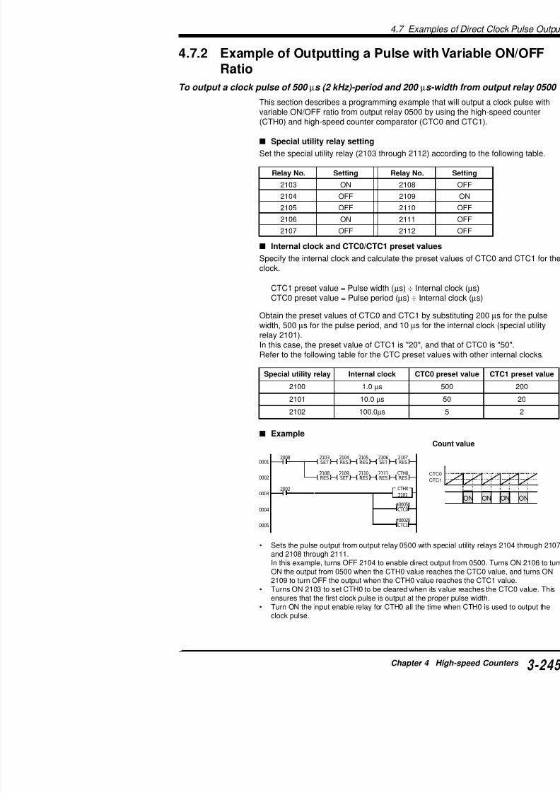
7/18/2019 Keyence Programming
http://slidepdf.com/reader/full/keyence-programming 269/392
2103SET
2104RES
2105RES
2106SET
2107RES
2108RES
2109SET
2110RES
2111RES
CTH0RES
20080001
0002CTC0
CTC1
width, 500 µs for the pulse period, and 10 µs for the inrelay 2101).In this case, the preset value of CTC1 is "20", and thaRefer to the following table for the CTC preset values
ExampleCoun
yalerytilitulaicepS kcolclanretnI serp0CTC
0012 0.1 µs 005
1012 0.01 µs 05
2012 0.001 µs 5
4.7 Examples of Direct Clock Pulse Output
VisualKV
Series
Coding
Note 1: When the input enable relay for the high-speed counter ithe clock pulse, the response is delayed by a maximum of one scstarts. The response is also delayed by a maximum of one scan Note 2: Refer to the following "Tips" to start and stop the clock p
Tips
• Use special utility relay 2105 to control (enable/disable) the cexternal inputs.
• Use the SET-RES pair or KEEP instruction to turn special utilOFF.
Line No. Instruction Operand Line No. Instructi
0000 LD 2008 0013 CON
0001 MPS 0014 SET
0002 SET 2103 0015 CON
0003 CON 0016 RES
0004 RES 2104 0017 CON
0005 CON 0018 RES
0006 RES 2105 0019 CON
0007 CON 0020 RES
0008 RES 2106 0021 LD
0009 CON 0022 CTH
0010 RES 2107 0023 CTC
0011 MPP 0024 CTC
0012 RES 2108

7/18/2019 Keyence Programming
http://slidepdf.com/reader/full/keyence-programming 270/392
4
0000
0000 2105RES
2105SET 0000
0000
With this setting, the clock pulse is always turned OFF when istops.
• When either of the following program is added to the examplepage, the clock pulse is output from 0500 only when 0000 is O
When SET-RES instructions are used When KEEP instruct
• You can change the period (frequency) of the clock pulse by cpreset value using the LDA and STA instructions.
T h th i d f th l k l f t "4 3 4 C t
4.7 Examples o
To output a clock pulse of 500 µs (2 kHz)-period and 200 µs-widt
This section describes a programming example that wvariable ON/OFF ratio from output relay 0501 by using(CTH1) and high-speed counter comparator (CTC2 an
Special utility relay setting
Set the special utility relay (2203 through 2212) accor
Internal clock and CTC2/CTC3 preset values
Specify the internal clock and calculate the preset valuclock.
CTC2 preset value = Pulse width (µs) ÷ Internal cloCTC3 preset value = Pulse period (µs) ÷ Internal c
Obtain the preset values of CTC2 and CTC3 by substwidth, 500 µs for the pulse period, and 10 µs for the inrelay 2201).
In this case, the preset value of CTC3 is "20", and thaRefer to the following table for the CTC preset values
.oNyaleR gnitteS .oNyaleR
3022 NO 8022
4022 FFO 9022
5022 FFO 0122
6022 NO 1122
7022 FFO 2122
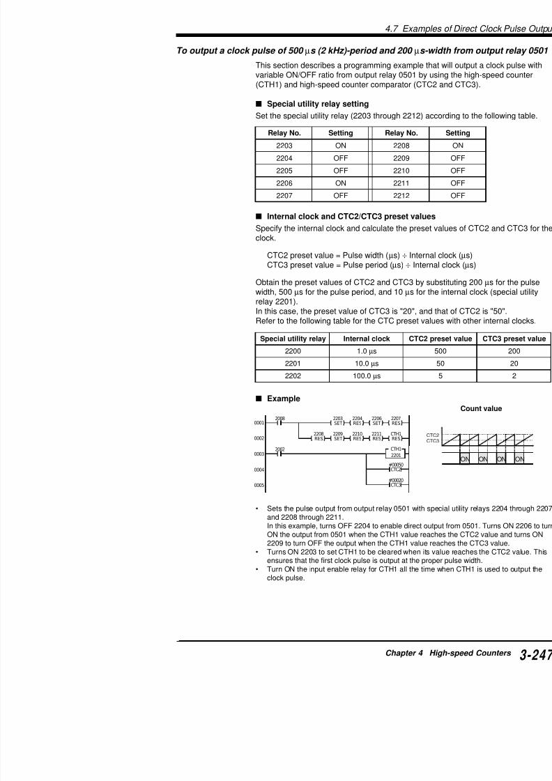
7/18/2019 Keyence Programming
http://slidepdf.com/reader/full/keyence-programming 271/392
2203SET
2204RES
2206SET
2207RES
2208RES
2209SET
2210RES
2211RES
CTH1RES
2008
2002
#00050CTC2
CTH1
2201
0001
0002
0003
0004
CTC2CTC3
g p
Example
yalerytilitulaicepS kcolclanretnI serp2CTC
0022 0.1 µs 005
1022 0.01 µs 05
2022 0.001 µs 5
4.7 Examples of Direct Clock Pulse Output
VisualKV
Series
Coding
Note :When the input enable relay for the high-speed counter is the clock pulse, the response is delayed by a maximum of one sc
starts. The response is also delayed by a maximum of one scan stops.
Tips
• Use special utility relay 2205 to control (enable/disable) the cexternal inputs.
• Use the SET-RES pair or KEEP instruction to turn special utilOFF.With this setting, the clock pulse is always turned OFF when istops.
• When either of the following programs is added to the examp
Line No. Instruction Operand Line No. Instruct
0000 LD 2008 0012 SET
0001 MPS 0013 CON
0002 SET 2203 0014 RES
0003 CON 0015 CON
0004 RES 2204 0016 RES
0005 CON 0017 CON
0006 SET 2205 0018 RES
0007 CON 0019 LD
0008 RES 2207 0020 CTH
0009 MPP 0021 CTC
0010 RES 2208 0022 CTC
0011 CON
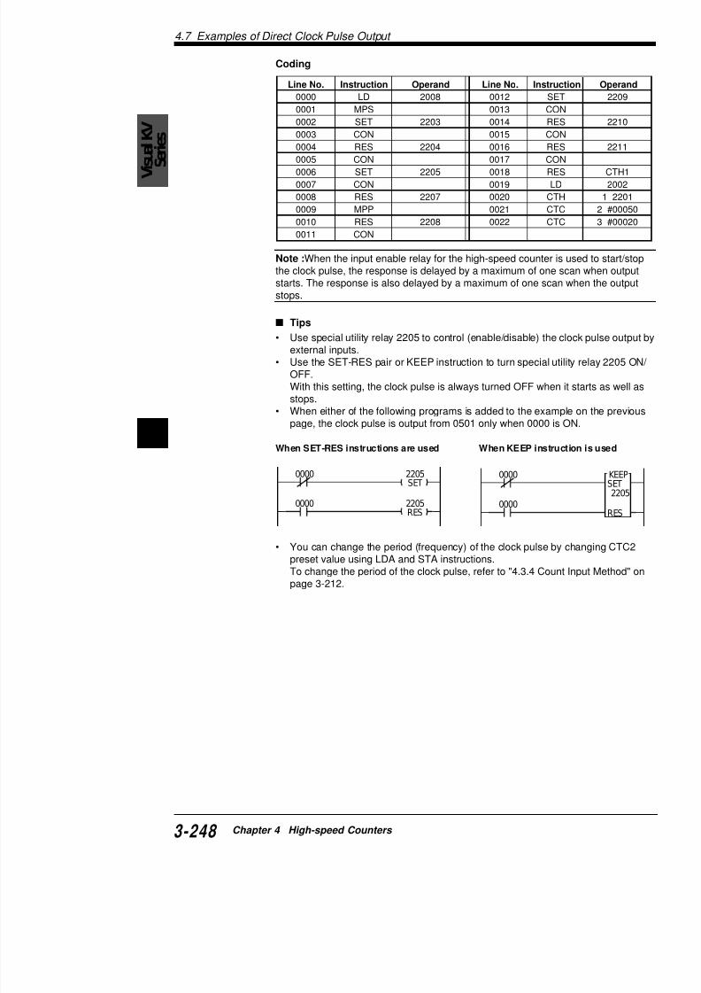
7/18/2019 Keyence Programming
http://slidepdf.com/reader/full/keyence-programming 272/392
4
0000
0000 2205RES
2205SET
0000
0000
When either of the following programs is added to the examppage, the clock pulse is output from 0501 only when 0000 is O
When SET-RES instructions are used When KEEP instruct
• You can change the period (frequency) of the clock pulse by preset value using LDA and STA instructions.To change the period of the clock pulse, refer to "4.3.4 Count page 3-212.
4.7 Examples o
2109SET
2110RES
2111RES
CTH0RES0002
2104RES
2105SET
2106SET
2107RES
2108RES
2103SETEI
20080001
4.7.3 Example of Stopping the Pulse OutpuPulse Count
This section describes a programming example that wµs (2 kHz)-period and 200 µs-width from output relay 10000 pulses are output.
Special utility relay, internal clock, and CTC set
Set the special utility relay according to the following t
Specify the internal clock and CTC0/CTC1 preset valu
table.
Example
.oNyaleR gnitteS .oNyaleR
3012 NO 8012
4012 FFO 9012
5012 FFO 0112
6012 NO 1112
7012 FFO 2112
yalerytilitulaicepS kcolclanretnI serp0CTC
0012 0.1 µs 005
1012 0.01 µs 05
2012 0.001 µs 5
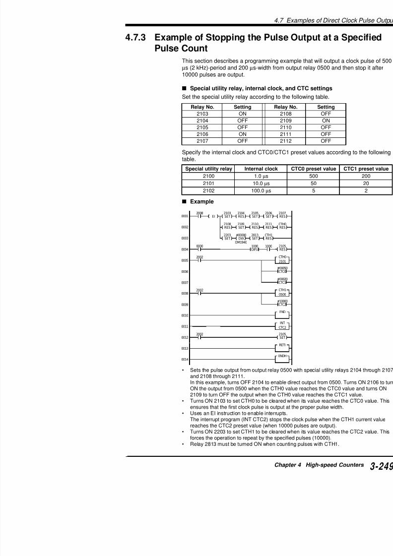
7/18/2019 Keyence Programming
http://slidepdf.com/reader/full/keyence-programming 273/392
2105RES
2105
SET
2203SET
2813SET
CTH1RES
2002
#00050CTC0
1000DIFU
#00020CTC1
CTH0
2101
1000
0003
0005
2002
0012
2002
#10000CTC2
CTH1
05000008
END0010
INT
CTC20011
00000004
0006
0009
0007
#00000DW
DM1940
4.7 Examples of Direct Clock Pulse Output
VisualKV
Series
• The input enable relay for CTH0 must be ON all the time when CTH
clock pulse.• The input enable relay for CTH1 must be ON all the time when CTH
clock pulse.• Specifies the internal clock (2101) as the clock input for CTH0. Spec
clock input for CTH1. With this setting, CTH0 is used to output the clis used to count the clock pulse.
• Specifies the number of clock pulses to the CTC2 preset value.• The clock pulse output starts when input 0000 is turned ON.
To restart the clock pulse output after it stops, turn ON input 0000 ag
Coding
Line No. Instruction Operand Line No. Instructi
0000 LD 2008 0024 SET
0001 EI 0025 CON
0002 CON 0026 DW
0003 MPS 0027 CON
0004 SET 2103 0028 SET
0005 CON 0029 CON
0006 RES 2104 0030 RES0007 CON 0031 LD
0008 SET 2105 0032 DIFU
0009 CON 0033 CON
0010 SET 2106 0034 AND
0011 CON 0035 RES
0012 RES 2107 0036 LD
0013 MRD 0037 CTH
0014 RES 2108 0038 CTC
0015 CON 0039 CTC0016 SET 2109 0040 LD
0017 CON 0041 CTH

7/18/2019 Keyence Programming
http://slidepdf.com/reader/full/keyence-programming 274/392
4
Tips
Special utility relays 2103 through 2111 can be turned ON/OFF band STA instructions instead of the SET-RES instructions.The example program below can be changed as follows by usinginstructions. The number of lines and steps can be reduced.
0017 CON 0041 CTH
0018 RES 2110 0042 CTC
0019 CON 0043 END
0020 RES 2111 0044 INT
0021 CON 0045 LD
0022 RES CTH0 0046 SET
0023 MPP 0047 RET1
0048 ENDH
2104
S
2105
S
2106
S
2107
S
2103
S
2008 2100
S
CTH0
S
$02682008
4.7 Examples o
4.7.4 Application of Direct Clock Pulse Out(Ramp-up/down control)
The following ramp-up/down control is available by seto DM0003)
Setting parameters
DM0000: fH [Hz] (Running frequency)DM0001: fL [Hz] (Start-up frequency)
DM0002: Acceleration rate [Hz/10 ms]DM0003: No. of pulses for positioning
CW
KV
24 VDC
FG
– +
–
+
–
+
5 VDC
+ –
CCW
0002
0001
0000
05020500
COM 0003
0501COM 0503
S t a r t
R e v e r s
e
o u t p u
t
E m
e r g e n c y
s t o p
Stepping
Twisted-pair cable
(
Specify va50000 Hz. than the fL
(fH - fL) / (A Must be 65
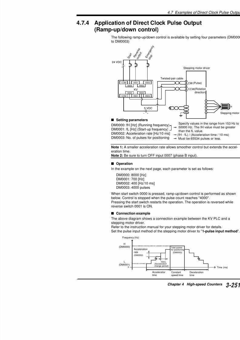
7/18/2019 Keyence Programming
http://slidepdf.com/reader/full/keyence-programming 275/392
Note 1: A smaller acceleration rate allows smoother ceration time.Note 2: Be sure to turn OFF input 0007 (phase B inpu
Operation
In the example on the next page, each parameter is s
DM0000: 8000 [Hz]DM0001: 700 [Hz]DM0002: 400 [Hz/10 ms]DM0003: 4000 pulses
When start switch 0000 is pressed, ramp-up/down conbelow. Control is stopped when the pulse count reachPressing the start switch restarts the operation. The o
4.7 Examples of Direct Clock Pulse Output
VisualKV
Series #08000
DW#00700
DW
$0268LDA
#01000LDA
#10000MUL
DM0012DIV
#00005ADD
#00010DIV
CTC0STA
DM0010STA
2100STA
1200SET
CTH1RES
CTH0RES EI
2105RES
#00400DW
#04000
DM0000 DM0001 DM0002 DM0003
DW2813SET
2105SET
2002
2008
0003
0001
2002
0000 1001
#00010CTC1
1001DIFU
#65535CTC0
CTH0
2100
0003 2105SET
#65535CTC2
#65535CTC3
01CALL
02CALL
CTH1
0500
END
RET
SBN
01
DM0003LDA
CTC3STA
#00002DIV
DM0004STA
DM0001LDA
DM0012STA
#00000DW
2002
#00010LDA
#10000MUL
DM0010DIV
#00005ADD
#00010DIV
DM0011ADD
CTC2STA
DM0011STA
SBN
02
0001
0002
0003
0004
0005
0006
0007
0008
0009
0010
0011
0012
0013
0014
0015
0016
0017
0018
0019
0020
0502
Specifies high-speedcounters and comparators
Starts positioning
Emergency stop
Calculation routine forCTC0, CTC2, and DM0011
Initialization routine
• CTC0 g
• CTH1 cclock p
CTC0:PuCTC1: PuCTC2:Fre
CTC3:To
• Sets paDM000
• Sets re
• Sets em
• Specifivalue.
DM0010:
DM0011:
DM0012:
1200: Acc
• SpecifieCTC0 p 1 ÷ D
Example
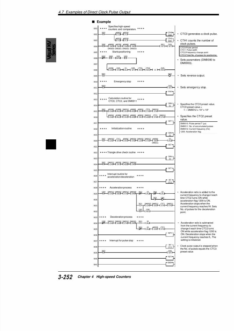
7/18/2019 Keyence Programming
http://slidepdf.com/reader/full/keyence-programming 276/392
4
Interrupt routine foracceleration/deceleration
Acceleration process
• Acceleracurrent ftime CTaccelera
CALL
RET
SBN
03
RET
LDA STA DIV STA LDA STADM0011
DW
DM0012LDA
#00100DIV
DM0011ADD
DM0004CMP
2002
0020
0021
0022
0023
0024
0025
DM0012LDA
DM0002ADD
DM0012STA
DM0000CMP
1200 2011
INT
CTC2
03CALL
2011
2011
02CALL
0026
0027
0028
0029
00301201
Triangle drive check routine
Chapter 5
Positioning Control
This chapter describes ramp-up/down control of stepp
For KV-10/80 Series, see Chapter 6.
5.1 Outline of Positioning Control ..........
5.1.1 Ramp-up/down Control ...............................
5.2 Parameter Setting and Operating Pro5.2.1 Parameter Setting Procedure......................5.2.2 Operating Procedure ...................................
5.3 Examples of Using the Positioning C5.3.1 Connection Example ...................................5 3 2 Tips
Visual KV Se

7/18/2019 Keyence Programming
http://slidepdf.com/reader/full/keyence-programming 277/392
5.3.2 Tips .............................................................5.3.3 Application Examples of the Positioning Con
5.1 Outline of Positioning Control
VisualKV
Series
5.1 Outline of Positioning ControlThis section describes the outline of positioning control.
5.1.1 Ramp-up/down Control
The Visual KV Series can directly output clock pulses not affecteto output relay 0502.
If the frequency, the number of output pulses, and the acceleratiopulses have been preliminarily set to data memories, the Visual Kcally performs ramp-up/down control.
The ramp-up/down control output function offers ramp-up/down tstartup frequency, operating frequency, acceleration time, and deshown below.
The output frequency can be set within the range of 200 to 50,00
Frequency (Hz)Number of outputpulses (pulses)
DM1485 and DM1484
OperatingfrequencyDM1481
Upper digit Lower digit
StartupfrequencyDM1480

7/18/2019 Keyence Programming
http://slidepdf.com/reader/full/keyence-programming 278/392
5
By using the ramp-up/down control output function, ramp-up/dowping motors and AC servo motors (pulse input types) is possible.
Accelerationtime DM1482
Deceletime D
Clock pulse
Rotation direction
5.2 Parameter Se
5.2 Parameter Setting and OpeProcedures
This section describes the parameter setting and opering control.
5.2.1 Parameter Setting Procedure
Preliminarily set each parameter for positioning contromemory. To operate, special utility relays must be set
For more about special utility relays, refer to "5.2.2 Operating P
The table below shows the relationship between para
Data memories for ramp-up/down control
yromemataD stnetnocgnitteS
0841MD putratslortnocnwod / pu-pmaR)zH(ycneuqerf
002
1841MD gnitarepolortnocnwod / pu-pmaR
)zH(ycneuqerf002
ulav(
2841MDlortnocnwod / pu-pmaR
emitnoitareleced / noitarelecca)sm(
ot0
4841MD sesluptuptuoforebmuN
)stib61rewol(ot0
ro2(
5841MD sesluptuptuoforebmuN)stib61reppu(
ot0
6841MD edocrorreeulavteS ehW
egni

7/18/2019 Keyence Programming
http://slidepdf.com/reader/full/keyence-programming 279/392
Note: When pulse output is started, the scan time is e(if the acceleration/deceleration time is set to 4 s).
Set value error code (DM1486)
If there is an error in the preset parameters when starterror code (11 to 17) is automatically written to DM148
egni
edoC noitpircseD
11 nahtrellamssieulavycneuqerfputratS.egnargnitteselbawolla
tratsteS2(egnar
21 rellamssieulavycneuqerfgnitarepO.egnargnitteselbawollanaht
repoteS2(egnar
5.2 Parameter Setting and Operating Procedures
VisualKV
Series
Operating frequency (Hz) (DM1481)
Set the frequency (speed) of the motor during operation in positioAt the set frequency, the Visual KV Series will output clock pulse
Note: If the startup frequency is the same as the operating frequchart becomes as shown below.
In this case, the acceleration/deceleration time is ignored.
Acceleration/deceleration time (ms) (DM1482)
Set the time to accelerate from the starting frequency to the operafter operation is started.When operation is stopped, the deceleration time is equivalent to
time.In the set time, the Visual KV Series varies the clock pulse frequestartup frequency to the operating frequency (in the case of acceThe clock pulse frequency change cycle within the acceleration t
0
Operating (startup)frequency
Operating frequency
St t f
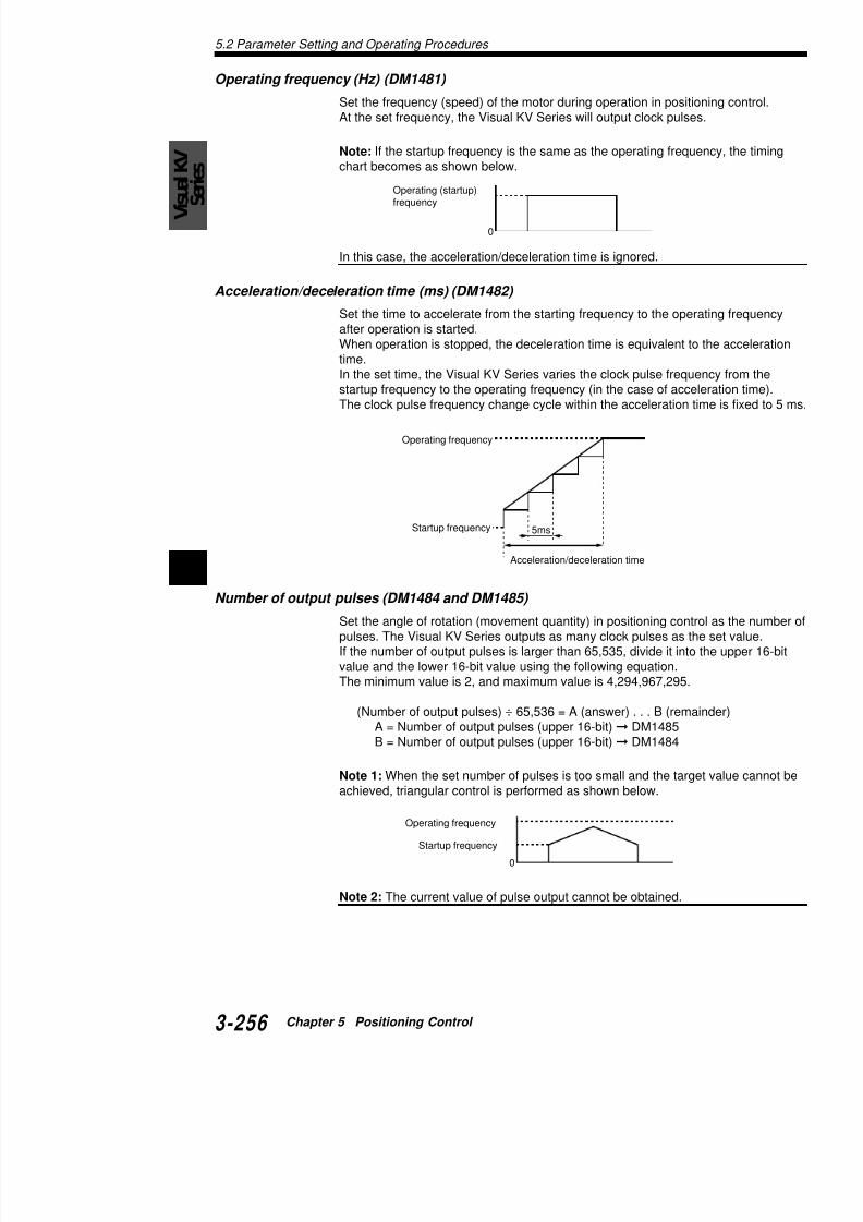
7/18/2019 Keyence Programming
http://slidepdf.com/reader/full/keyence-programming 280/392
5
Number of output pulses (DM1484 and DM1485)
Set the angle of rotation (movement quantity) in positioning contrpulses. The Visual KV Series outputs as many clock pulses as thIf the number of output pulses is larger than 65,535, divide it into value and the lower 16-bit value using the following equation.The minimum value is 2, and maximum value is 4,294,967,295.
(Number of output pulses) ÷ 65,536 = A (answer) . . . B (remaA = Number of output pulses (upper 16-bit) DM1485
5msStartup frequency
Acceleration/deceleration time
5.2 Parameter Se
5.2.2 Operating ProcedureIn positioning control, operation is started up, stoppedemergencies by the ON/OFF status of special utility reThe table below shows the relationship between operarelays used.
Operation chart
ytilitulaicepS.oNyaler *W/R noitcnuF D
8032 W potS noitarelecedsmrofreP
.noitarepo
9032 R
WnuR
TESER
upelihwNOsniameRemminoitarepospotS
.margorptpurretni
0132 W tratS tanoitarepopustratS
DM1480:DM1481:DM1482:DM1485:DM1484:
DM1481
DM1480
2310
(START)
2309
(RUN)
0
DM1485
DM1484
DM1482 DM1482
When reloutput (d
While cloremains Ooutput, re

7/18/2019 Keyence Programming
http://slidepdf.com/reader/full/keyence-programming 281/392
Note 1: If there is no error in the parameter setting wh
turns ON at startup of the clock pulses, special utility rpulses are output.
Note 2: If there is an error in the parameter setting, spnot turn ON but a corresponding error code is written
Confirm the error code, and change the erroneously s
Note 3: By setting special utility relay 2309 to OFF in pulses can be immediately stopped.
Note 4: Rising of special utility relay 2310, falling of sp
( )
2308
(STOP)
p ,
When reldeceleratedge).
5.3 Examples of Using the Positioning Control Function
VisualKV
Series
5.3 Examples of Using the PositionControl Function
This section describes examples of connecting a stepping motor ing ramp-up/down control using the positioning control function oSeries.
5.3.1 Connection ExampleConnect the Visual KV Series and stepping motor driver as showThis example is only for reference. For details, refer to the instrucstepping motor driver.Set the pulse input type of the stepping motor driver to "1 pulse in
CW
Visual KV
24 VDC
–
+
–
+
+
–
CCW0002
0001
0000
R0502
CO M
CO M R0503
E m e r g e n c
y s t o
p
S t o
p
S t a
r t
Stepping motor drive
Twisted pair cable
(pulse)
(rotationdirection)
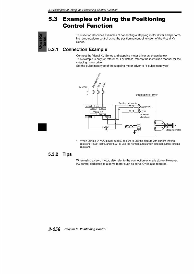
7/18/2019 Keyence Programming
http://slidepdf.com/reader/full/keyence-programming 282/392
5
• When using a 24 VDC power supply, be sure to use the outputs withresistors (R500, R501, and R502) or use the normal outputs with extresistors.
5.3.2 Tips
When using a servo motor, also refer to the connection example I/O control dedicated to a servo motor such as servo ON is also r
FG
5 VDC*
+ –
5.3 Examples of Using t
5.3.3 Application Examples of the PositioninFunction
Ladder example of ramp-up/down control
When start switch 0000 is set to ON, output 0502 starwith a startup frequency of 500 Hz, operating frequencdeceleration time of 3 seconds.When input 0001 is set to ON, pulse output is deceler
When input 0002 is set to ON, pulse output is immedi
Program example
0 100000
500
1000
Speed (Hz)
2008
2002
EI0001
0002
0003
0004
#34464DW
#00001DW
#03000DW
#10000DW
#00500
DM1484DM1485DM1482DM1481DM1480DW
0000 2310
0001 2308
HSP0002

7/18/2019 Keyence Programming
http://slidepdf.com/reader/full/keyence-programming 283/392
0004
0005
0006
0007
0008
0009
2309
RES
RETI
ENDH
END
INT0002
2002
5.3 Examples of Using the Positioning Control Function
VisualKV
Series
Ladder example of the jog operation
The jog operation is performed.
• While input 0000 is ON, the machine continues to move in theWhen input 0000 turns OFF, the machine decelerates and sto
• While input 0001 is ON, the machine continues to move in thWhen input 0001 turns OFF, the machine decelerates and sto
Program example
1000
500
Speed (Hz)CW direction CCW dir
Input 0000(CW direction)
Input 0001
(CCW direction)
1000DIFU
0503SET
0001 230900000001

7/18/2019 Keyence Programming
http://slidepdf.com/reader/full/keyence-programming 284/392
5
DIFU
0000 0001
#65535DW
#65535DW
#01000DW
#02000DW
#00500
DM1484DM1485DM1482DM1481DM1480
DW1000
1100
1001
SET
2310
2308
END
ENDH
1001DIFU
1100DIFU
0503RES
0000 23090001
0001
0002
0003
0004
0005
0006
5.3 Examples of Using t
Ladder example of automatic operation (palletizing operation)
A palletizing operation is automatically performed.The machine moves to a target coordinate, then returnthe machine moves to a position further away than thereturns to the start position. Such an operation is realreturn movements. This type of operation is suitable foworkpieces to be supplied are located in one position the workpieces and positions them little by little at a ce
When start signal 0000 is set to ON, a moving body mstart position, moves to point 2, and then returns to thwards, the moving body moves to point 3, then returns05000 remains ON for 3 seconds, and then the opera
Program example
5000
0
5000
500
500
Speed (Hz)
P
Point 1: 10,000 CP
#00000DW
#03000DW
#05000DW
#00500DW
0001
0002
00030000
Ladder for automatic operation
Point 1: 10,000 Point 2: 12,000 Point 3: 14,000
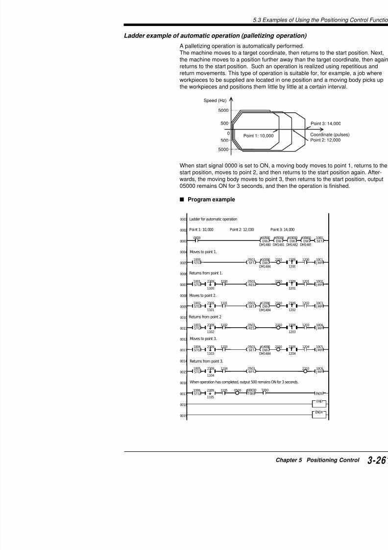
7/18/2019 Keyence Programming
http://slidepdf.com/reader/full/keyence-programming 285/392
DWDWDWDWDM1485DM1482DM1481DM1480
0003
0004
0005
0006
0007
0008
0009
0010
0011
#10000
DM1484DW
2310 1000STG
0503SET
#12000
DM1484DW
2310 1002STG
0503SET
1100 2310 1001STG
2309
1100
1102 2310 1003STG
0503RES
2309
1102
11012309
1101
12012309
1201
12002309
1200
12032309
1203
12022309
1202
0503RES
Moves to point 1.
Returns from point 1.
Moves to point 2.
Returns from point 2
5.3 Examples of Using the Positioning Control Function
VisualKV
Series
Ladder example of a return to the zero point
A return to the zero point is performed.
When start signal 0000 turns ON, the machine moves at a high sdirection. When the zero point sensor turns ON, the machine deca low speed in the CW direction, then stops in the position at whisensor turns OFF (at the end of the CW direction).
Program example
Range detected byzero point sensor
Low speedForced stop
Decelerationand stop High-speed
0001
0002
0003
0004
0005
0006
2008
2002
EI
HSP0003
Return to zero point
Zero point sensor: 0003 Start signal: 0000 Pulse output: 0502Rotation direction: 0503
Initial setting
Moves at high speed in the CCW direction.

7/18/2019 Keyence Programming
http://slidepdf.com/reader/full/keyence-programming 286/392
50007
0008
0009
0010
0011
0012
0013
0014
1005SET
#65535DW
#00000DW
#00500DW
#10000DW
#00500
DM1484DM1485DM1482DM1481DM1480DW
0503RES
2413RES
1000DIFU
0000 1000 2309
1007DIFU
1005 10072309
0503SET
2413SET
#65535DW
#00000DW
#00500DW
#10200DW
#00200
DM1484DM1485DM1482DM1481DM1480DW
1006 2309
2310
1006
END
INT
2308RES
When the zero point sensor turns ON, moves at low speed in the CW direction.
Detects the rising/falling edge of the zero point sensor (003), stops, andthen changes direction.
5.3 Examples of Using t
Ladder example of an automatic operation (continuous operation
In automatic operation, wait status is realized at each
When start signal 0000 turns ON, the machine movesthe rising edge of wait status reset switch 1, the machpoint 2 and stops there. At the rising edge of waiting smachine automatically moves to point 3. When the ma0500 remains ON for 3 seconds and the operation is f
Program example
0 250000 320000
500
5000
10000
7000
Speed (Hz)
Wait Wait
0001
0002
0003
0004
0005
0006
0007
0000
#01000
DM1481DW
#01000
DM1482DW
#00003
DM1485DW
#53392
DM1484DW
2310 1000STG
0503SET
Ladder for automatic operation (continuous operation with wait status)
Start signal: 0000 Pulse output: 0508 Rotation direction: 0503
Wait reset switch: 0001
Moves to point 1 at speed of 10 kHz. Acceleration/deceleration timMoving quantity: 250,000 pulses
Moves to point 2 at speed of 5 kHz. Acceleration/deceleration tim
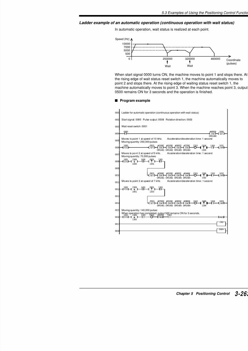
7/18/2019 Keyence Programming
http://slidepdf.com/reader/full/keyence-programming 287/392
0007
0008
0009
0010
0011
0012
0013
0014
0015
1400
#05000
DM1481
DW#01000
DM1482
DW#00001
DM1485
DW#04464
DM1484
DW2310 0503
SET
#07000
DM1481DW
0503SET
1001STG
2309
1400
13010001
1301
1401
#01000
DM1482DW
#00002
DM1485DW
#08928
DM1484DW
2310
1002STG
2309
1401
13030001
1303
p pMoving quantity: 70,000 pulses
Moves to point 3 at speed of 7 kHz. Acceleration/deceleration tim
Moving quantity: 140,000 pulsesWhen operation has completed, output 500 remains ON for 3 seconds
5.3 Examples of Using the Positioning Control Function
VisualKV
Series
0001
0002
Ladder example of a pulse motor application circuit
This is a program example which offers control using both automoperations.In automatic operation, when input 000 is set to ON, the followingperformed.
In manual operation, the machine moves forward while input 000backward while input 0009 is ON. When input 0007 is set to ON,returns to the zero point.Output 0502 outputs pulses. The rotation direction is changed by0503.This machine is equipped with a zero-point sensor (0002), a forw(0006), and a backward limit switch (0004).
Program example
0 15000 175
300
15000
2000
8000
Speed (Hz)
Pulse motor application circuit (with zero point sensor, forwardlimit switch, and backward limit switch)
Specifications
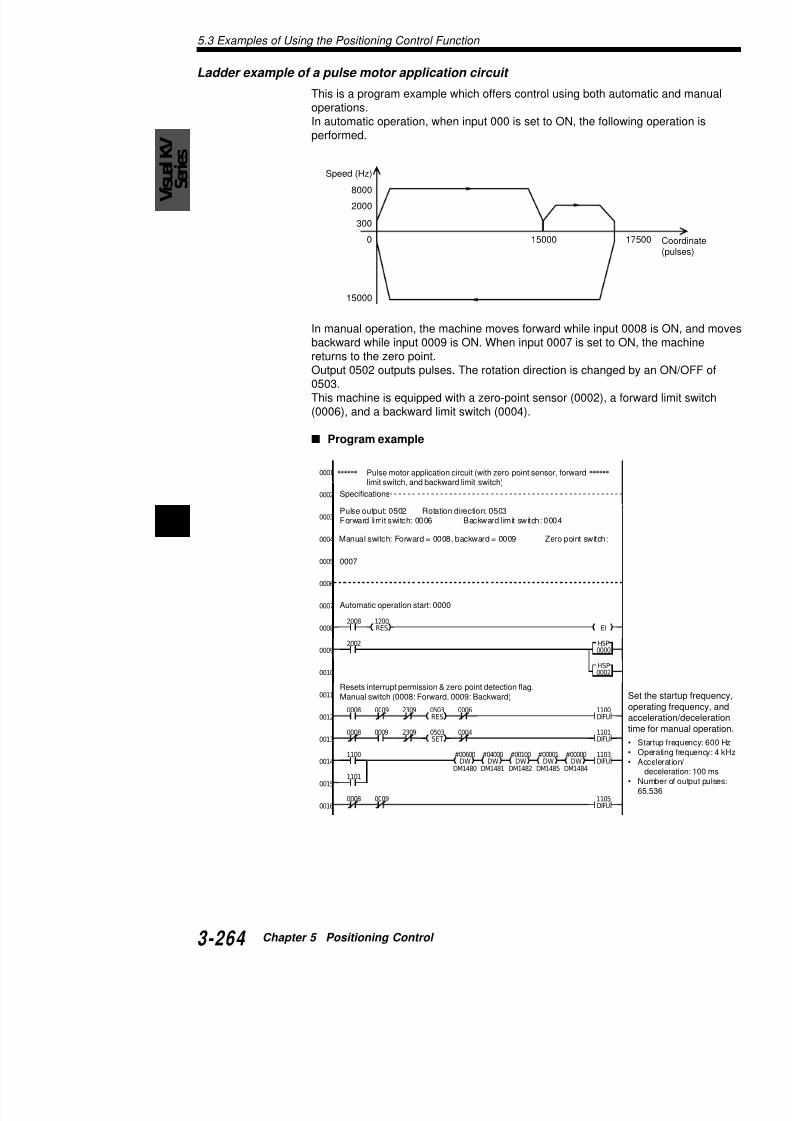
7/18/2019 Keyence Programming
http://slidepdf.com/reader/full/keyence-programming 288/392
5
2008EI
0002
0003
0004
0005
0006
0007
0008
0009
0010
1200RES
2002 HSP0000
HSP0002
Specifications
Pulse output: 0502 Rotation direction: 0503Forward limit switch: 0006 Backward limit switch: 0004
Manual switch: Forward = 0008, backward = 0009 Zero point switch:
0007
Automatic operation start: 0000
5.3 Examples of Using t
0007
#03500DW
#00000DW
#00250DW
#03000DW
#00300
DM1484DM1485DM1482DM1481DM1480DW
1300DIFU
1205
0006
0015
0016
0017
0018
0019
0020
0021
0022
0023
0024
0025
0026
0027
0028
0029
0030
0031
0032
0033
1203DIFU
#65535DW
#00000DW
#00000DW
#00500DW
#00500
DM1484DM1485DM1482DM1481DM1480DW
0503SET
1200
1301DIFU
0503RES
1203
1300
1301 0004
1506 2308
1103
00090006
0004 0008
1105
2309ON
1201
1201 12022309OFF1202
Return to zero point
Limit switch
Move forward.
Trigger end of forward movement
While moving backward at low speed, return to zero point.
Start up motor.
Decelerate and stop (in manual/automatic operation).
Automatic operation
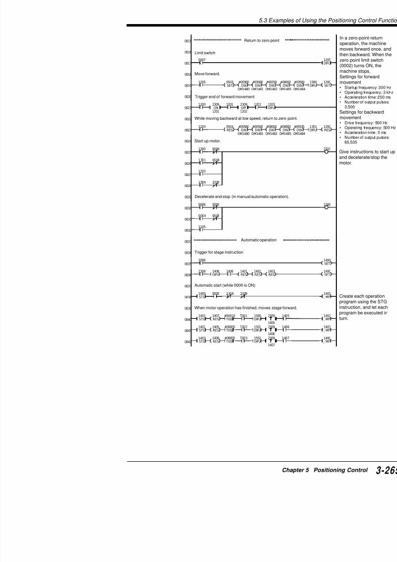
7/18/2019 Keyence Programming
http://slidepdf.com/reader/full/keyence-programming 289/392
2309
1405
2008
0034
0035
0036
0037
0038
0039
0040
0041
0042
1408DIFU
1402RES
1403RES
1401RES
2308
1400STG
1401STG
#00010 T001
1500DIFU
0000
1408
1407RES
T001 1405
2309
1406
1402STG
#00005 T002
1501DIFU
1405RES
T002 1406
23091403STG
#00005 T003
1502DIFU
1406RES
T003 1407
2308 2309
Trigger for stage instruction
Automatic start (while 0000 is ON)
When motor operation has finished, moves stage forward.
5.3 Examples of Using the Positioning Control Function
VisualKV
Series
2309RES
#17500DW
#00000DW
#00250DW
#15000DW
#00300
DM1484DM1485DM1482DM1481DM1480DW
1505DIFU
0503RES
1502
1200 0008 0009 0000
15061503
END
RETI
ENDH
INT0002
1504
1505
#15000DW
#00000DW
#00150DW
#08000DW
#00300
DM1484DM1485DM1482DM1481DM1480DW
1503DIFU
0503SET
1500
#02500DW
#00000DW
#00250DW
#02000DW
#00300
DM1484DM1485DM1482DM1481DM1480DW
1504DIFU
0503SET
1501
0043
0044
0045
0046
0047
0048
0049
0050
0051
0052
0053
0054
0055
0056
Set automatic operation parameters.Set
mat1. SOAN1
2. SOAN2
3. SO
AN1
Start up motor.
Interrupt for instantaneous stop (to return to zero point)Stozerinte

7/18/2019 Keyence Programming
http://slidepdf.com/reader/full/keyence-programming 290/392
5
Chapter 6
Interrupts, High-speed Counte
Positioning ControlThis chapter describes ramp-up/down control of stepp
6.1 Interrupt Instructions ........................6.1.1 Description of Interrupts ..............................6.1.2 Interrupt Instructions ...................................
6.2 Direct Clock Pulse .............................
6.2.1 Output of Direct Clock Pulse .......................6.3 Positioning Control ...........................6.3.1 Positioning Control (Ramp-up/down Control
KV-300, KV-
7/18/2019 Keyence Programming
http://slidepdf.com/reader/full/keyence-programming 291/392
6.1 Interrupt Instructions
KV-300
K V
- 1 0 / 8 0
6.1 Interrupt Instructions6.1.1 Description of Interrupts
Input processing for routine program and interrupt routine
Routine program flow is shown by the thick arrow on the left of Finput signals can be received only during input processing.
Although input time constant can be made shorter by using HSP special utility relay 2813 input signals can be received only if the
Input processing
Output processing
Routine program
executionInterrupt routine
execution S c a n t i m e
G e n e
r a t i o n
o f i n t e r
r u p t
R e t u r n s t o s u s p e n d e d p r o g r a m
a t t h e p o i n t o f s u s p e n s i o n .
Fig. 1

7/18/2019 Keyence Programming
http://slidepdf.com/reader/full/keyence-programming 292/392
6
special utility relay 2813, input signals can be received only if thethe duration of one scan time.
When an interrupt initiation input turns ON, the currently running pended to immediately execute the interrupt routine.
During execution of interrupt routine, input signals shorter than oreceived by the PLC.
Note: To execute INT (interrupt initiation instruction), execute EI interrupt, then use HSP (time constant: 25 µs) or turn ON specia(time constant: 10 µs) to reduce the input time constant.
2008
EI
2813SET or
2002
2002
Interrupt priority
If two or more interrupts are generated at different timexecuted in the order that interrupts are generated.If two or more interrupts are generated simultaneouslyexecuted according to the priority shown below.CTC0 > CTC1 > CTC2 > CTC3 > 0000 > 0001 > 0002
* Note that the above priority differs from that for oth80).
The priority is: 0000 > 0001 > 0002 > 0003 > CTC2
Note 1: During execution of one interrupt routine, exetines is inhibited. (One interrupt routine can be executroutine by inserting EI.)
Note 2: If other interrupts are generated during executhe routines of these interrupts are executed after comroutine in the order that they are generated. Note that
interrupt nesting or up to 8 individual interrupts can beinterrupt routine. However, generation of an interrupt isame interrupt has already been stored.
Interrupt routine2008
EI
2813
SET
END
INTXXXXX
RETI

7/18/2019 Keyence Programming
http://slidepdf.com/reader/full/keyence-programming 293/392
• Execute EI to enable interrupt.• Be sure to insert INT between END and ENDH.• Be sure to shorten the input time constant by using
utility relay 2813.
Instructions that cannot be used in the INT-RETI b
TMR, TMH, TMS, DIFU, DIFD, W-ON, W-OFF, W-UEHKEY, ITVL, @xxxx (instruction), C, UDC, SFT
RETI
ENDH
6.1 Interrupt Instructions
KV-300
K V
- 1 0 / 8 0
Direct output
Direct output is enabled only through output relays 0500, 0501, 0This function allows ON/OFF status of any of output relays 0500,0503 to be output during execution of interrupt routine.This function allows immediate ON/OFF status output without detime.
Note: Be sure to turn ON special utility relay 2813 to shorten the
Direct input
2008
EI
2813
SET
END
INT0000
0500
( SET )
RETI
INT0001
ENDH
0500( SET )
2002
2002
2008 2813
SET

7/18/2019 Keyence Programming
http://slidepdf.com/reader/full/keyence-programming 294/392
6END
RETI
ENDH
05001000
INT 0000
10000005
6.1.2 Interrupt Instructions
DI: Interrupt Disabled Disab
EI: Interrupt Enabled Enab
Key operations
Operand
Example
Coding
: DIAND8FNC RES
0
: EISET1FNC ORL
3
ORL3
AND8 ENT
R-SRCH
RES0FNC
SET1FNC
ENTR-SRCH
1000 EI
1000
DI
Line No. Instruction Operand
0000 LD 1000
0001 EI
: :
0021 LDB 1000
0022 DI

7/18/2019 Keyence Programming
http://slidepdf.com/reader/full/keyence-programming 295/392
Description
When 1000 is ON, execution of interrupt is enabled. Wof interrupt is disabled. Interrupts are enabled betweetion.Therefore, once EI is executed, interrupt is enabled un
With the KV, any interrupt is disabled when the operatDI instruction disables execution of interrupt. Use this disable interrupt.EI instruction enables the execution of interrupt. Use t
00
: :
6.1 Interrupt Instructions
KV-300
K V
- 1 0 / 8 0
INT: Interrupt
RETI: Return Interrupt
Key Operations
Operand
0000 to 0003CTC0 to CTC3
Example 1
Input pulse width shorter than one scan time (eg. one-shot c
: nnnn
INT
FNC RES0
ANL2
:RETI
ORL3FNC LDB
4
ENTR-SRCH
RES0
LDB4
ENTR-SRCH
Operand ENTR-SRCH
ENTR-SRCH
FNC
FNC
ANL2
ORL3
0000(a)
0000
(Input remains ON for 1 ms or more.)
2008
EI2813SET
0500 0500
#00020 T000
T000
#00020 T000
1000
(b)
0000
Input forroutineprogram
Input forinterruptroutine
Executes interrupt betweinstructions at rising edgeby operand. When 0003 operand, the rising or falselected for execution of
Represents termination o
INT / RETI

7/18/2019 Keyence Programming
http://slidepdf.com/reader/full/keyence-programming 296/392
6
0500 0500T000
END
INT0000
RETI
ENDH
10002002
(Input remains ON for 10 µs or more.)
Interrupt routine coding
Example 2
Features of INT0003
Upon generation of interrupt by INT0003, the CTH1 cutransferred to TM30.Interrupt generated by any of INT0000 to INT0002 is ethe input signal. Interrupt generated by INT0003 can b
or falling edge of the input signal.
In the example program below, pulse width of input 00
0003 Pulse width
ON
OFF
2206(OFF) 2206(ON) 2008
1 E
2002
2
Relay No. ON
2206 Executes interrupts at falling edge of Execinput pulse to 0003. input
Line No. Instruction Operand Line No.
0000 LD 2008 0008
0001 EI 0009
0002 CON 0010
0003 SET 2813 0011
0004 LD 1000 0012
0005 OR 0500 0013
0006 TMR 000 #00020 0014
0007 ANB T000

7/18/2019 Keyence Programming
http://slidepdf.com/reader/full/keyence-programming 297/392
Coding
2206
2206
TMLD
TMLD
3
4
6.1 Interrupt Instructions
KV-300
K V
- 1 0 / 8 0
INT / RETI
2008
1 EI2203
2002 CTH100052
0000
3
CTH1 #05000CTC2 SET
2813
0501
SET RES
RES
Initial setting
• When the operation is started, EI instruction enables interrupt
• Special utility relays No. 2200 through 2215 are turned OFF. Tdisables CTC2 from resetting the CTH1 current value to 0.
• Turning OFF 2206 allows interrupt to be generated at the risin
• The value of DM0000 is reset to "0".
• Turning ON special utility relay 2813 changes the input time c
• 1.0-µs internal clock pulses are counted using CTH1.• INT instruction with 0003 as the operand allows interrupts to b
• When interrupt is generated for the first time, 2206 is OFF. Thrung (a) is executed. Then, KEEP turns 2206 ON.
• When interrupt is generated for the second time, 2206 is ON. in rung (b) is executed to calculate the following:
(TM30 at 2nd execution) - (TM30 at 1st execution) = pulse
The result is stored in DM0000.
Example 3
Interrupt by CTC
Pulses input to 0005 are counted. 0501 is turned ON when the nreaches 5,000.

7/18/2019 Keyence Programming
http://slidepdf.com/reader/full/keyence-programming 298/392
6
2002
END
INT
CTC2
RETI
4
5
0501
SET
ENDH
Initial setting
• When the operation is started, EI instruction enabl
• Turning ON special utility relay 2203 allows CTC2 value to 0.
• The CTH1 current value is reset to 0.
• The CTC2 preset value is set to 5000.
• Turning ON special utility relay 2813 changes the i
• Pulses input to 0005 are counted using CTH1.• When input 0000 turns ON, output 0501 is reset.
• INT CTC2 is used to execute the interrupt. (Interruthe CTH1 current value and CTC2 preset value are
• Immediate output to 0501 is performed.
Note 1: When the interrupt is executed, the contact of
Note 2: The operand used for INT instruction is not alinstructions.
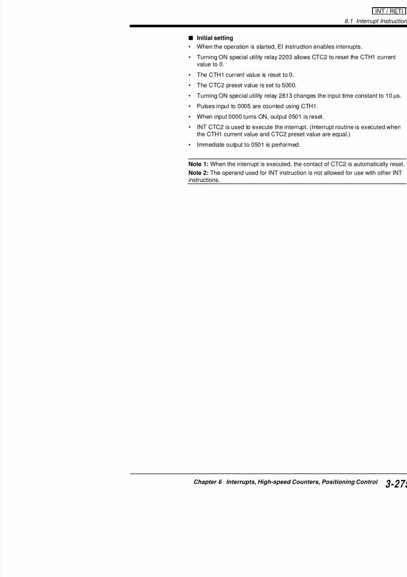
7/18/2019 Keyence Programming
http://slidepdf.com/reader/full/keyence-programming 299/392
6.2 High-speed Counters
KV-300
K V
- 1 0 / 8 0
Internal clocks2200(1.0 µs)2201(10.0 µs)2202(100.0 µs)External pulse0005/00070500
Internal clocks2100(1.0 µs)2101(10.0 µs)2102(100.0 µs)
External pulse0004/0006
Spec(2103
Spec(2203
INT INT
INT INT
TM30
Phase A 0004Phase B (0006)
0009 (RESET)
0008 (RESET)
Phase A 0005Phase B (0007)
Con
Con
16-bithigh-speed counterCTH0
16-bit high-speed counterCTH1
High-speedcounter comparatorCTC0, CTC1
High-speedcounter comparatorCTC2, CTC3
6.2 Direct Clock Pulse6.2.1 Output of Direct Clock Pulse
Outline of High-Speed Counters
Basic Architecture
The KV-300 CPU has two 16-bit (CTH0, CTH1) double-phase co
equipped with two high-speed counter comparators (CTC0, 1, 2, can be used as a stepping motor controller or are used to measu
Block diagram of high-speed counters
Lists of special utility relays for high-speed counters
Utility relays for high-speed counter CTH0
2100 Internal clock (1.0 µs) for CTH0

7/18/2019 Keyence Programming
http://slidepdf.com/reader/full/keyence-programming 300/392
6
2101 Internal clock (10.0 µs) for CTH0
2102 Internal clock (100.0 µs) for CTH0
2103 When comparator CTC0 is ON, automatically clears CTH0.
1: Yes 0: No2104 Direct output to 0500 Direct output level to 0500
1: Disable 0: Enable CTC1 (any one of these is
2105 Turns OFF output to 0500.1: Yes 0: No
2106 Turns ON output to 0500.1: Yes 0: No
2107 Reverses output (toggle) to 0500.1: Yes 0: No
Utility relays for high-speed counter CTH1
2200 Internal clock (1.0 µs) for CTH1
2201 Internal clock (10.0 µs) for CTH1
2202 Internal clock (100.0 µs) for CTH1
2203 When comparator CTC2 is ON, automatically clear1: Yes 0: No
2204 Direct output to 0501 through comparator CTC21: Enable 0: Disable
2205 Direct output level to 0501 through comparator CTC
1: ON 0: OFF2206 Selection of INT3 edge
0: UP edge 1: DOWN edge
2207 Reverse output (toggle) level1: ON 0: OFF
2208 Direct output to 0501 Direct output le1: Disable 0: Enable CTC3 (any one
2209 Turns OFF output to 0501.1: Yes 0: No
2210 Turns ON output to 0501.1: Yes 0: No
2211 Reverses output (toggle) to 0501.1: Yes 0: No
2212 When comparator CTC3 is ON, automatically clear1: Yes 0: No
2213 Uses CTH1 in magnification mode.1: Yes 0: No
2214 Selection of magnification mode for CTH11: x 4 0: x 2
2215 Enables external reset for CTH1.1: Yes 0: No
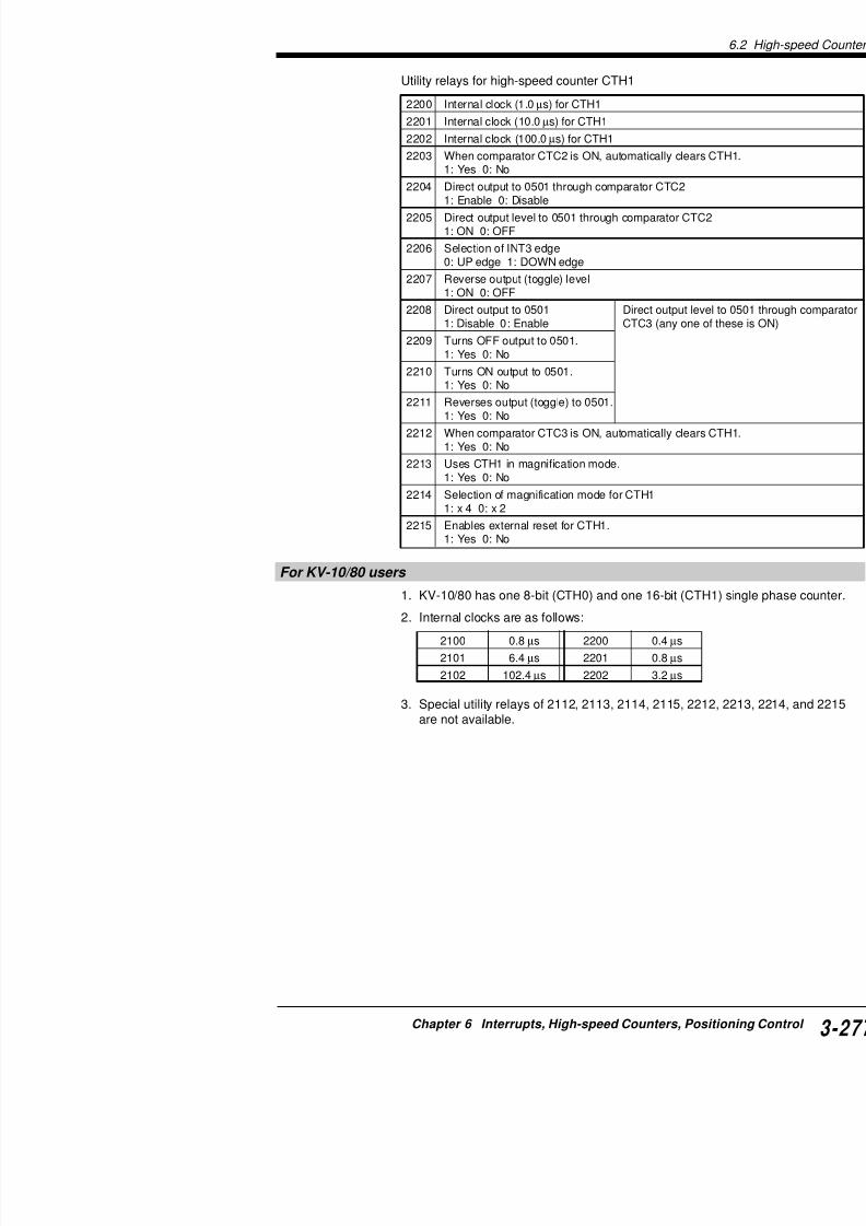
7/18/2019 Keyence Programming
http://slidepdf.com/reader/full/keyence-programming 301/392
For KV-10/80 users
1. KV-10/80 has one 8-bit (CTH0) and one 16-bit (CT
2. Internal clocks are as follows:
3. Special utility relays of 2112, 2113, 2114, 2115, 22are not available.
2100 0.8 µs 2200 0.4 µs
2101 6.4 µs 2201 0.8 µs
2102 102.4 µs 2202 3.2 µs
6.2 High-speed Counters
KV-300
K V
- 1 0 / 8 0
High-speed counter and counter comparators
High-speed counter (CTH1)CTH1 is a 16-bit hardware counter that counts from 0 to 65535.
• You can specify the operands listed in the table below as the • You can specify one operand from the table below.• Operand cannot be modified externally during execution of th• When the external pulse (0004, 0005) is selected, CTH1 is us
counter with a response frequency of 30 kHz.*• When one of the internal clocks (2100 to 2102, 2200 to 2202)
is used as a High-speed timer.• When the external pulse 0500 is selected as input to CTH1, Cdirect clock pulses generated by CTH0.
* KV-10/80: 10 kHz
High-speed counter comparator (CTC)
High-speed counter comparators (CTC) is used only for High-speWhen the current value of CTH reaches the preset value of one o(CTC), the comparator turns ON.At the contact of High-speed counter comparator (CTC), the leve0501) can be changed (directly output) through hardware or an ingenerated. To change the level of output 0500 and 0501, set the OFF) to special utility relays 2103 to 2112, 2203 to 2205, and 22
The High-speed counters correspond to the High-speed counter
High-speed counter CTH0 CTH1
Operand 2100 22002101 22012102 22020004 0005
0500
Countable range 0 to 65535
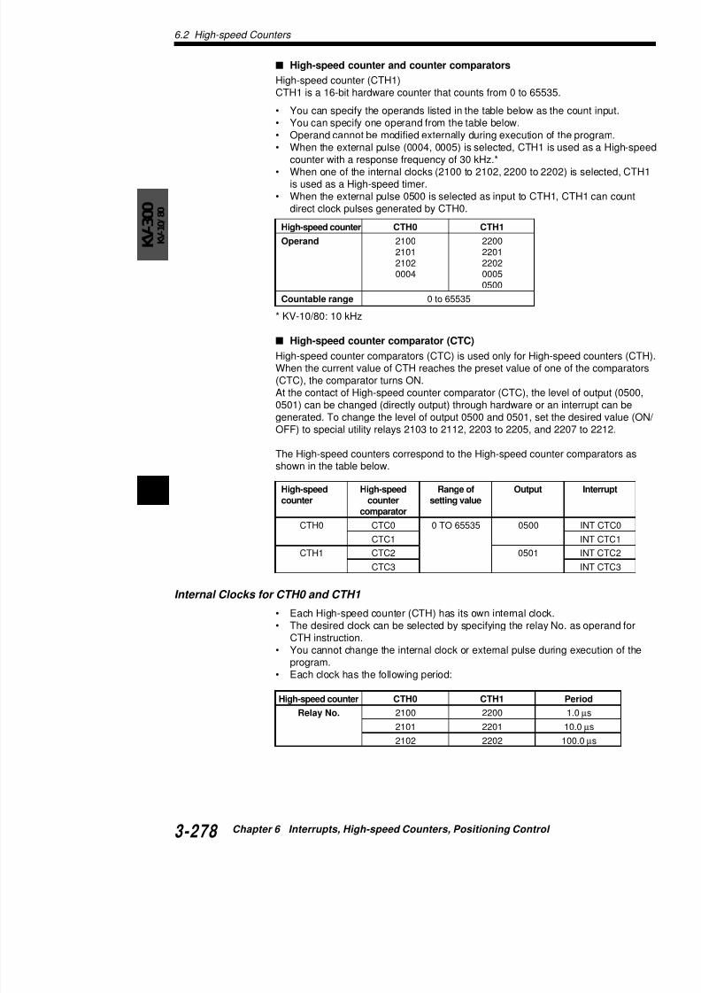
7/18/2019 Keyence Programming
http://slidepdf.com/reader/full/keyence-programming 302/392
6
shown in the table below.
Internal Clocks for CTH0 and CTH1
High-speed High-speed Range of Outputcounter counter setting value
comparator
CTH0 CTC0 0 TO 65535 0500
CTC1
CTH1 CTC2 0501
CTC3
• You cannot change operands of the high-speed
execution of the program. The input time constcounters is usually set to 25 ms. (The HSP inst
• High-speed pulses can be counted at up to 30 k(0004 to 0007) by turning ON special utility relabe counted at up to 50 kHz by turning ON 2813.
* KV-10/80 : 10 kHz
Outline of Pulse OutputThe KV PLC can output clock pulses through 0500 ancaused by scan time. (Through CPU only)Direct clock pulses, used with the high-speed countertypes of production control such as for controlling targTo perform ramp-up/down control, see "Controlling steA setting of the clock pulse cycle (frequency) can be cthe allowable range as shown in the table below.
Outline of pulse output
Direct clock pulses are output through 0500 and/or 05the special utility relays when the number of internal chigh-speed counter reaches the preset value of the co
CAUTION
Output Internal clock Range of
0500 2100 20 µs (50 kHz)
2101 20 µs (50 kHz)
2102 200 µs (5 kHz)
0501 2200 20 µs (50 kHz)
2201 20 µs (50 kHz) 2202 200 µs (5 kHz)
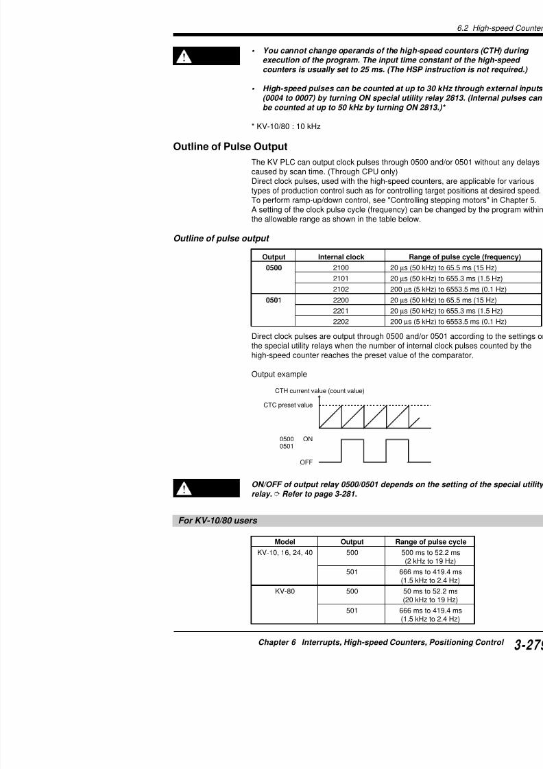
7/18/2019 Keyence Programming
http://slidepdf.com/reader/full/keyence-programming 303/392
high speed counter reaches the preset value of the co
Output example
CTH current value (count value)
CTC preset value
ON
OFF
05000501
6.2 High-speed Counters
KV-300
K V
- 1 0 / 8 0
Pulse period and width
Period and width of the pulse is determined by the period of the iused and the preset value of the comparator (CTC).When two counter comparators are used, only the pulse width caa constant period is maintained.The following examples illustrate how pulse width and period can
ON/OFF ratio of 1:1
Pulse width (ms) = CTC0 preset value x internal clock (ms)
Pulse period (ms) = CTC0 preset value x 2 x internal clock (ms)
• ON/OFF ratio of pulse is 1:1.• Change CTC0 preset value to change the pulse width and pe
Variable pulse width
ON/OFF status is set by special utility relays.Pulse width (ms) = CTC1 preset value x internal clock (ms)Pulse period (ms) = CTC0 preset value x internal clock (ms)
• Change CTC1 preset value to change the pulse width.• Change CTC0 preset value to change the pulse period.
ON
OFFPulse
widthPulse period
ON/OFF status is set special utility relays
ON
OFF
ON/ OFF status is set by special utility relays

7/18/2019 Keyence Programming
http://slidepdf.com/reader/full/keyence-programming 304/392
6The pulse width determined as above is used to pulses geneKV-300 CPU.Pulses are output through the output circuit. The pulse widting on the response delay from the output circuit and influennected load. Before setting the pulse width, you should meawaveform using an oscilloscope. (Use pulses with variable p
• To obtain the pulse cycle from frequency, use the following exPulse cycle (µs) 1000 ÷ Frequency (kHz)
Pulse period
Pulsewidth
CAUTION
Special utility relay settings and output statuses
16-bit high-speed counter (CTH0) and special u
By setting the special utility relays 2104 to 2112 at staduring generation of clock pulse, you can select ON/Olisted below.These special utility relays also allow you to set the puand enable or disable the direct output.
• Special utility relay must be ON when clock pul
• Only one of relays 2104 to 2107 and one of relaturned ON. When two or more of the relays amopriority is given to the relay with the smallest N
• Turning OFF special utility relays 2104 and 210Because these relays are factory-set to ON, be
• ON/OFF status of special utility relays 2104 to 2RES instructions or STA instruction.
CAUTION
Pulse status at CTH0 (current value) = CTC (p
Comparator No. Relay No. Pu
CTC0 2103 Automatically c
2104 Disables output
2105 Outputs OFF to
2106 Outputs ON to
2107 Inverts output to
CTC1 2112 Automatically c
2108 Disables output
2109 Outputs OFF to2110 Outputs ON to
2111 Inverts output to

7/18/2019 Keyence Programming
http://slidepdf.com/reader/full/keyence-programming 305/392
• Be sure to turn the special utility relay 2103 or 2pulse width. Turn ON 2103 or 2112 to change th
• Turn OFF 2105 to start clock pulse output. Turnoutput.
• When special utility relays 2104 and 2108 are tuclock pulses are being output, the status of theand the pulses will be stopped.
Timing diagram of 0500 with special utility relay
• ON-OFF ratio of 1:1 • Varia
6.2 High-speed Counters
KV-300
K V
- 1 0 / 8 0
16-bit high-speed counter (CTH1) and special utility relay
2208 to 2212)By setting the special utility relays 2204 to 2205 and 2208 to 221changing these relays during generation of clock pulse, you can output relay 0501 as listed below.These special utility relays also allow you to set the pulse cycle
• Special utility relay must be ON when clock pulse is gene
• Only one of relays 2208 to 2211 can be turned ON. When relays among each group are ON, priority is given to the smallest No.
• Turning ON special utility relay 2204 and turning OFF spe2208 enable direct output.
• ON/OFF status of special utility relays 2204 to 2212 is set RES instructions or STA instruction.
• Be sure to turn the special utility relay 2203 or 2212 ON towidth.
• Turn ON 2203 or 2212 to change the pulse cycle.
CAUTION
Pulse status at CTH1 (current value) = CTC (preset value
Comparator No. Relay No. Pulse status
CTC2 2203 Automatically clears current
2204 Disables output to 0501.
2205 Outputs OFF to 0501
2207 Inverts output to 0501.
CTC3 2212 Automatically clears current
2208 Disables output to 0501.
2209 Outputs OFF to 0501
2210 Outputs ON to 0501.
2211 Inverts output to 0501.
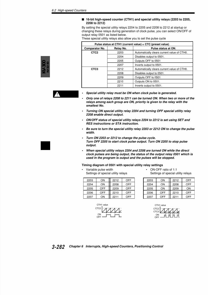
7/18/2019 Keyence Programming
http://slidepdf.com/reader/full/keyence-programming 306/392
6
Turn ON 2203 or 2212 to change the pulse cycle.Turn OFF 2205 to start clock pulse output. Turn ON 2205 output.
• When special utility relays 2204 and 2208 are turned ON wclock pulses are being output, the status of the output reused in the program is output and the pulses will be stop
Timing diagram of 0501 with special utility relay settings
• Variable pulse width • ON-OFF ratioSettings of special utility relays Settings of sp
2203 ON 2212 OFF 2203 ON
Calculating the pulse cycle and comparator setting value
The KV-300 CPU supports clock pulse output at maxiObtain the pulse cycle for clock pulse output and comfollowing expressions:• Pulse cycle
Pulse cycle (µs) = 1000 ÷ Frequency (kHz)• For pulse with 1:1 ON/OFF ratio (using one compa
CTC setting value = Pulse cycle (µs) ÷ Internal clo
• For pulse with variable pulse width (using two comCTC setting value for pulse width = Pulse width (µsCTC setting value for pulse cycle = Pulse cycle (µs
Range of CTC setting based on internal clock
• When setting 2100 or 2200 for the operand of H
ON
OFF
Pulsewidth
Pulse cycle
ON
OFFPulsewidth
Pulse cycle
CAUTION
Special utility relay (Internal clock) Cycle2100 2200 1.0 µs
2101 2201 10.0 µs
2102 2202 100.0 µs
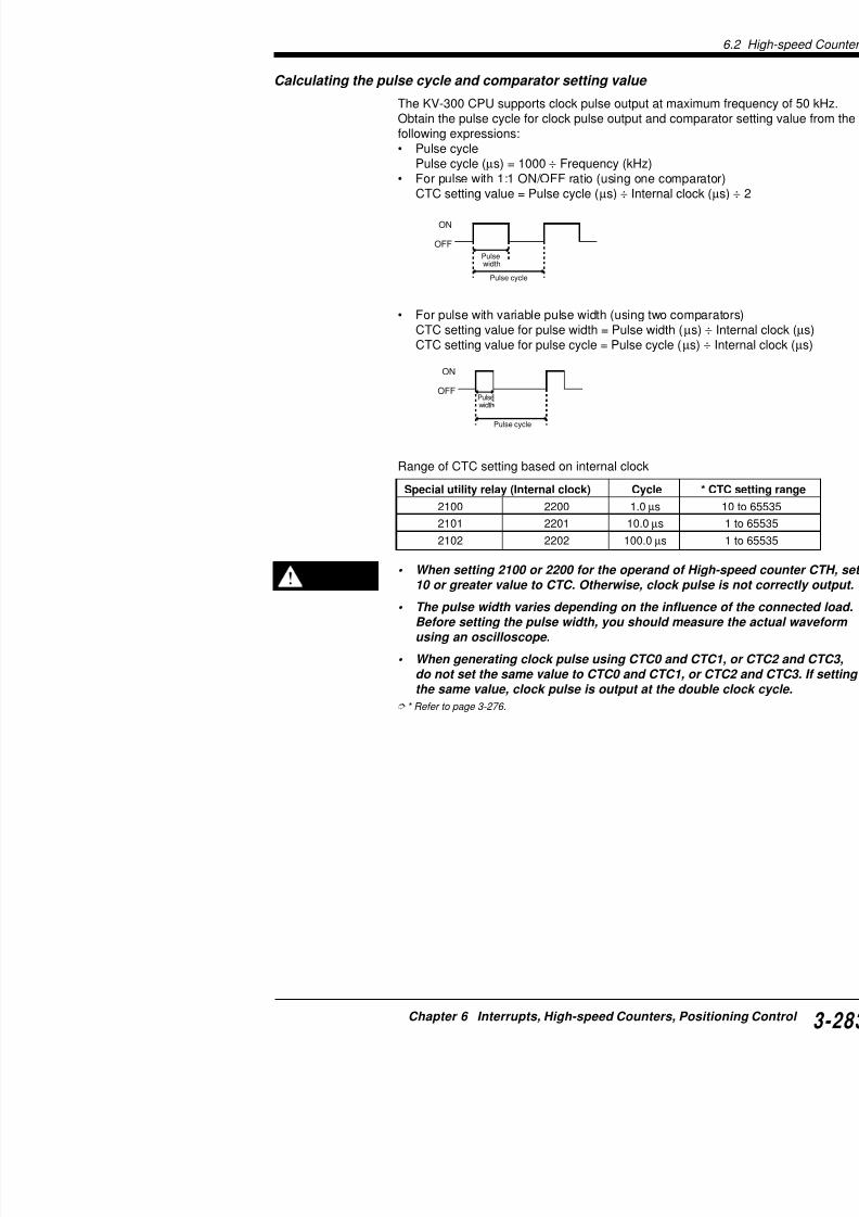
7/18/2019 Keyence Programming
http://slidepdf.com/reader/full/keyence-programming 307/392
When setting 2100 or 2200 for the operand of H10 or greater value to CTC. Otherwise, clock pu
• The pulse width varies depending on the influe
Before setting the pulse width, you should meausing an oscilloscope.
• When generating clock pulse using CTC0 and Cdo not set the same value to CTC0 and CTC1, othe same value, clock pulse is output at the do
* Refer to page 3-276.
CAUTION
6.2 High-speed Counters
KV-300
K V
- 1 0 / 8 0
Examples of Pulse Output
The following sample explains how to program the pulse output.
Example of clock pulse with 1:1 ON/OFF ratio
When outputting clock pulse with cycle 1 ms (1 kHz) from
This program example shows how to output clock pulse with 1:1 0500, through High-speed counter CTH0 and High-speed counteCTC0.
Setting special utility relays
Special utility relays 2103 to 2112 are set as shown on the right tThe program can be simplified using reverse output (toggle) for pOFF ratio.
Values set to the internal clock and CTC0
After the internal clock is determined, the CTC0 setting value is cfollowing expression.
CTC0 setting value = Pulse cycle (µs) ÷ Internal clock (µs) ÷ 2Assign 1 ms to pulse cycle and 10 µs (2101: special utility relay) and calculate the CTC0 setting value.The calculated result is "50".CTC0 values calculated based on other internal clocks are listedreference.
Relay No. Setting Relay No. Setting
2103 ON 2112 OFF
2104 OFF 2108 OFF
2105 OFF 2109 OFF2106 OFF 2110 OFF
2107 ON 2111 OFF
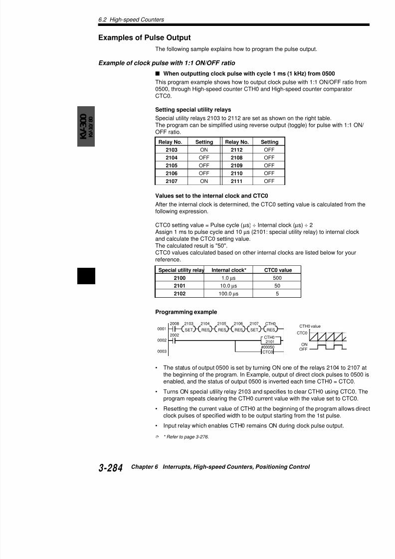
7/18/2019 Keyence Programming
http://slidepdf.com/reader/full/keyence-programming 308/392
6
Programming example
Special utility relay Internal clock* CTC0 value
2100 1.0 µs 500
2101 10.0 µs 502102 100.0 µs 5
2008
SET
2103 2104 2105 2106 2107
2002
0001
0002
CTH0
2101
RES RES RES SET RES
CTH0
CTH0 valu
CTC0
KEEP InstrucSET/RES Instructions
Coding
Line No. Instruction Operand
0000 LD 2008
0001 SET 2103
0002 CON
0003 RES 2104
0004 CON
0005 RES 2105
0006 CON
0007 RES 2106
0008 CON
0009 SET 2107
0010 CON
0011 RES CTH0
0012 LD 2002
0013 CTH 0 2101
0014 CTC 0 #00050
When start/stop of clock pulse is controlled by thedisables the high-speed counter, response relay oat start. Also, the same response relay is generateclock pulse output while the output relay is still ON
This controls clock pulse so that it always starts and s
Turn ON/OFF special utility relay 2105 as required to direct clock pulses using one of the external clocks. Utogether or only KEEP instruction to turn ON/OFF thisThe diagram below can be added to the sample diagrare output through 0500 only when 0000 is ON.
CAUTION
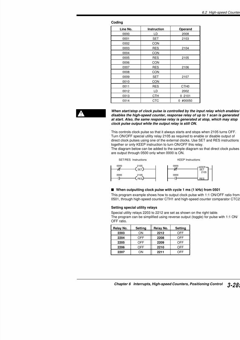
7/18/2019 Keyence Programming
http://slidepdf.com/reader/full/keyence-programming 309/392
0000 2105
0000
SET
2105
RES
0000
0000
When outputting clock pulse with cycle 1 ms (1
This program example shows how to output clock puls0501, through high-speed counter CTH1 and high-spe
Setting special utility relays
6.2 High-speed Counters
KV-300
K V
- 1 0 / 8 0
Values set to the internal clock and CTC2
After the internal clock is determined, the CTC2 setting value is cfollowing expression.
CTC2 setting value = Pulse cycle (µs) ÷ Internal clock (µs) ÷ 2Assign 1 ms to pulse cycle and 10 µs (2201: special utility relay) and calculate the CTC2 setting value.The calculated result is "50".CTC2 values calculated based on other internal clocks are listedreference.
* Refer to page 3-276.
Programming example
• The status of output 0501 is set by turning ON one of the relathe beginning of the program. In Example, output of direct clo
enabled, and the status of output 0501 is inverted each time C
• Turns ON special utility relay 2203 and specifies to clear CTHprogram repeats clearing the CTH1 current value with the val
• Resetting the current value of CTH1 at the beginning of the pclock pulses of specified width to be output starting from the 1
Special utility relay Internal clock* CTC0 value2200 1.0 µs 500
2201 10.0 µs 50
2202 100.0 µs 5
2008
SET
2203 2204 2205 2207
2002
0001
0002
0003
CTH1
2201
SET RES SET RES
CTH1
CTC2#00050
CTH1 va
ONOFF
CTC2

7/18/2019 Keyence Programming
http://slidepdf.com/reader/full/keyence-programming 310/392
6• Input relay which enables CTH1 remains ON during clock pul
Coding
Line No. Instruction Operand
0000 LD 2008
0001 SET 2203
0002 CON
0003 SET 2204
0004 CON
0000 2204
0000
SET
2204
RES
0000
0000
KEEP InstrucSET/RES Instructions
When start/stop of clock pulse is controlled by the
disables the high-speed counter, response relay oat start. Also, the same response relay is generateclock pulse output while the output relay is still ON
This controls clock pulse so that it always starts and sTurn ON/OFF special utility relay 2204 as required to direct clock pulses using one of the external clocks. Utogether or only KEEP instruction to turn ON/OFF thisThe diagram below can be added to the sample diagr
are output through 0501 only when 0000 is ON.
CAUTION
Example of clock pulse with variable ON/OFF ratio When outputting clock pulse with cycle 500 µs
200 µs from 0500
This program example shows how to output clock puls0500, through high-speed counter CTH0 and high-speCTC0 and CTC1.
Setting special utility relays
Special utility relays 2103 to 2112 are set as shown in
Relay No. Setting Relay No. Setting
2103 ON 2112 OFF
2104 OFF 2108 OFF
2105 OFF 2109 ON
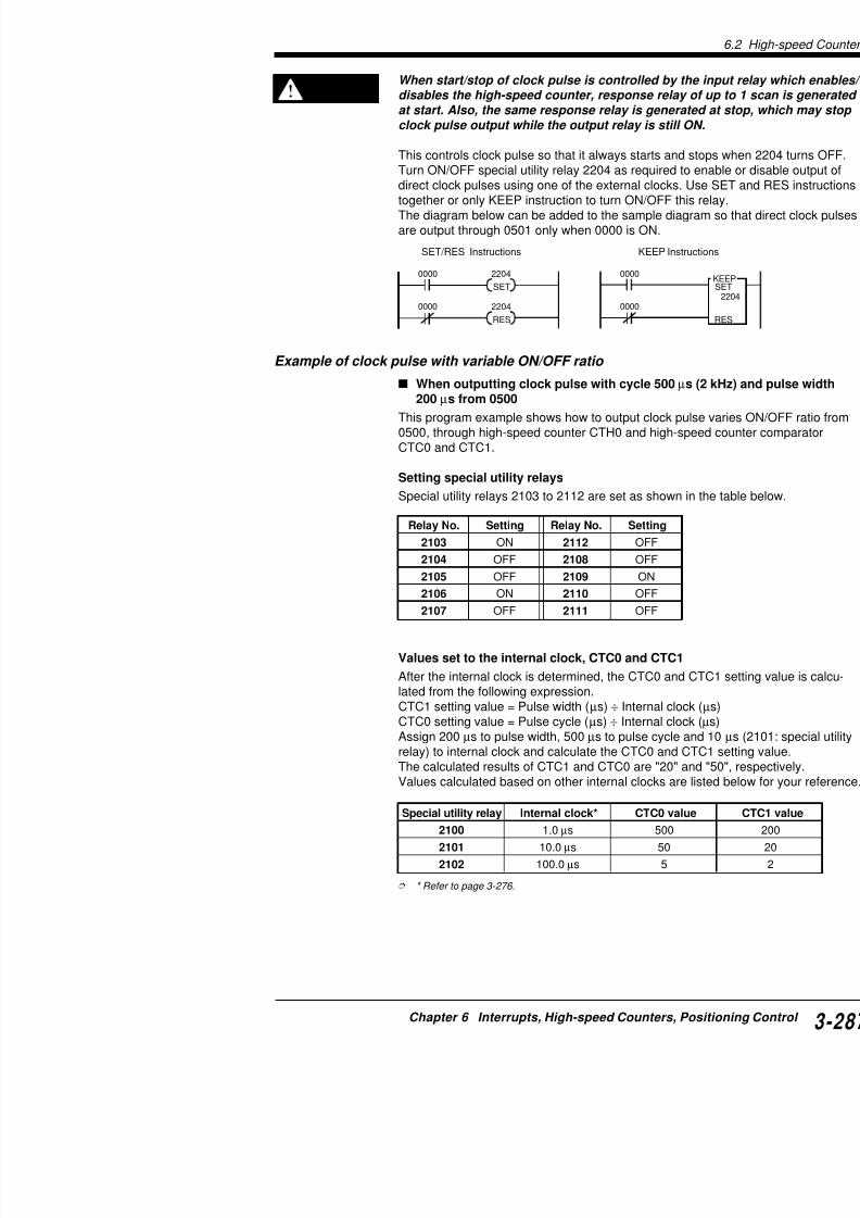
7/18/2019 Keyence Programming
http://slidepdf.com/reader/full/keyence-programming 311/392
Values set to the internal clock, CTC0 and CTC1
After the internal clock is determined, the CTC0 and Clated from the following expression.CTC1 setting value = Pulse width (µs) ÷ Internal clockCTC0 setting value = Pulse cycle (µs) ÷ Internal clockAssign 200 µs to pulse width, 500 µs to pulse cycle an
2106 ON 2110 OFF
2107 OFF 2111 OFF
6.2 High-speed Counters
KV-300
K V
- 1 0 / 8 0
Programming example
2008SET2103 2104 2105 2106
2002
0001
0002
0003 2101
RES RES SET RES
CTH0
CTC0#00050
0004
0005
RES
2108 2109 2110 2111 CTH0
SET RES RES RES
2107
CTC1#00020
CTH0
ONOFF
CTC0
CTC1
• The status of output 0500 is set by turning ON one of the relaand 2108 to 2111 at the beginning of the program. In Exampleclock pulses to 0500 is enabled, and the status of output 0500CTC0 and is turned OFF at CTC1.
• Turns ON special utility relay 2103 and specifies to clear CTHprogram repeats clearing the CTH0 current value with the val
• Input relay which enables CTH0 remains ON during clock pul
Coding
Line No. Instruction Operand Line No. Instructi
0000 LD 2008 0013 CON
0001 MPS 0014 SET
0002 SET 2103 0015 CON
0003 CON 0016 RES
0004 RES 2104 0017 CON0005 CON 0018 RES
0006 RES 2105 0019 CON
0007 CON 0020 RES
0008 SET 2106 0021 LD
0009 CON 0022 CTH
0010 RES 2107 0023 CTC

7/18/2019 Keyence Programming
http://slidepdf.com/reader/full/keyence-programming 312/392
6
When start/stop of clock pulse is controlled by the input reladisables the high-speed counter, response relay of up to 1 sat start. Also, the same response relay is generated at stop, clock pulse output while the output relay is still ON.
This controls clock pulse so that it always starts and stops when
CAUTION
0010 RES 2107 0023 CTC
0011 MPP 0024 CTC
0012 RES 2108
When outputting clock pulse with cycle 500 µs
µs from 0501This program example shows how to output clock pulsfrom 0501, through High-speed counter CTH1 and HigCTC2 and CTC3.
Setting special utility relays
Special utility relays 2203 to 2212 are set as shown o
Relay No. Setting Relay No. Setting
2203 ON 2212 OFF2204 ON 2208 OFF
2205 ON 2209 ON
2206 OFF 2210 OFF
2207 OFF 2211 OFF
Values set to the internal clock and CTC2 and CTC
After the internal clock is determined, the CTC2 and C
lated from the following expression.CTC3 setting value = Pulse width (µs) ÷ Internal clockCTC2 setting value = Pulse cycle (µs) ÷ Internal clockAssign 200 µs to pulse width, 500 µs to pulse cycle anrelay) to internal clock and calculate the CTC2 and CTThe calculated results of CTC3 and CTC2 are "20" anValues calculated based on other internal clocks are lence.
Special utility relay Internal clock* CTC2 value2100 1.0 µs 500
2101 10.0 µs 50
2102 100.0 µs 5
*Refer to page 3-276.
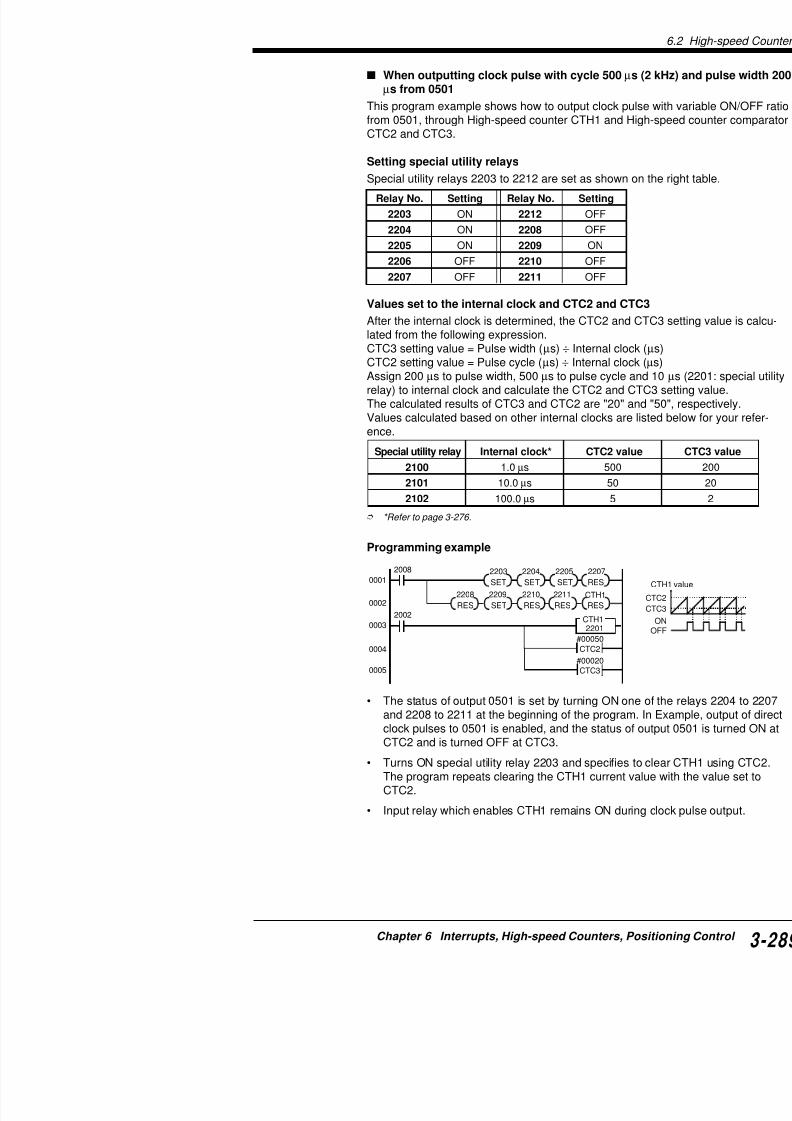
7/18/2019 Keyence Programming
http://slidepdf.com/reader/full/keyence-programming 313/392
Programming example
2008
SET2203 2204 2205
2002
0001
0002
0003 2201
SET SET RES
CTH1
CTC2#00050
0004
0005
RES
2208 2209 2210 2211 CTH1
SET RES RES RES
2207
CTC3#00020
6.2 High-speed Counters
KV-300
K V
- 1 0 / 8 0
0000 2204
0000
SET
2204
RES
0000
22040000
SET
RES
KEEP
KEEP InstructionsSET/RES Instructions
When start/stop of clock pulse is controlled by the input reladisables the high-speed counter, response relay of up to 1 sat start. Also, the same response relay is generated at stop,
clock pulse output while the output relay is still ON.
This controls the clock pulse so that it always starts and stops whOFF.
Turn ON/OFF special utility relay 2205 as required to enable or ddirect clock pulses using one of the external clocks. Use SET antogether or only KEEP instruction to turn ON/OFF this relay.The diagram below can be added to the sample diagram so that
are output through 0501 only when 0000 is ON.
CAUTION
Coding
Line No. Instruction Operand Line No. Instruc0000 LD 2008 0012 SET
0001 MPS 0013 CON
0002 SET 2203 0014 RES
0003 CON 0015 CON
0004 SET 2204 0016 RES
0005 CON 0017 CON
0006 SET 2205 0018 RES
0007 CON 0019 LD
0008 RES 2207 0020 CTH
0009 MPP 0021 CTC
0010 RES 2208 0022 CTC
0011 CON
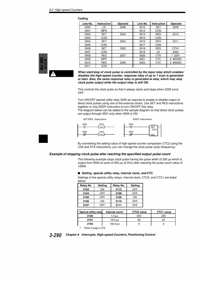
7/18/2019 Keyence Programming
http://slidepdf.com/reader/full/keyence-programming 314/392
6RES RES
By overwriting the setting value of high-speed counter comparatoLDA and STA instructions, you can change the clock pulse cycle
Example of stopping clock pulse after reaching the specified output pulse
The following example stops clock pulse having the pulse width ooutput from 0500 at cycle of 500 µs (2 kHz) after reaching the pu10000.
Programming example
2008SET2103 2104 2105 2106
2002
0001
0002
0003
2101
RES SET SET RES
CTH0
CTC0
#00050
0004
0005
RES
2108 2109 2110 2111 CTH0
SET RES RES RES
2107
CTC1
#00020
END
INTCTC2
2002
SET
2105
RET1
ENDH
SET
2203 2813
SET
2105
RES
CTH1
RES
EI
0000 1000
DIFU
1000
0006
0007
2002
0500CTH1
CTC2
#10000
0008
0009
0010
0011
0012
0013
0014
• Sets pulse output to 0500 using special utility relay2111.
The example on the left sets special utility relays to(2104: OFF), and turn 0500 output ON at CTC0 (2(2109: ON).
• Turns ON special utility relay 2103 to clear CTH0 uwith correct clock pulse width starting from the 1st
• Enables interrupt using the EI instruction.
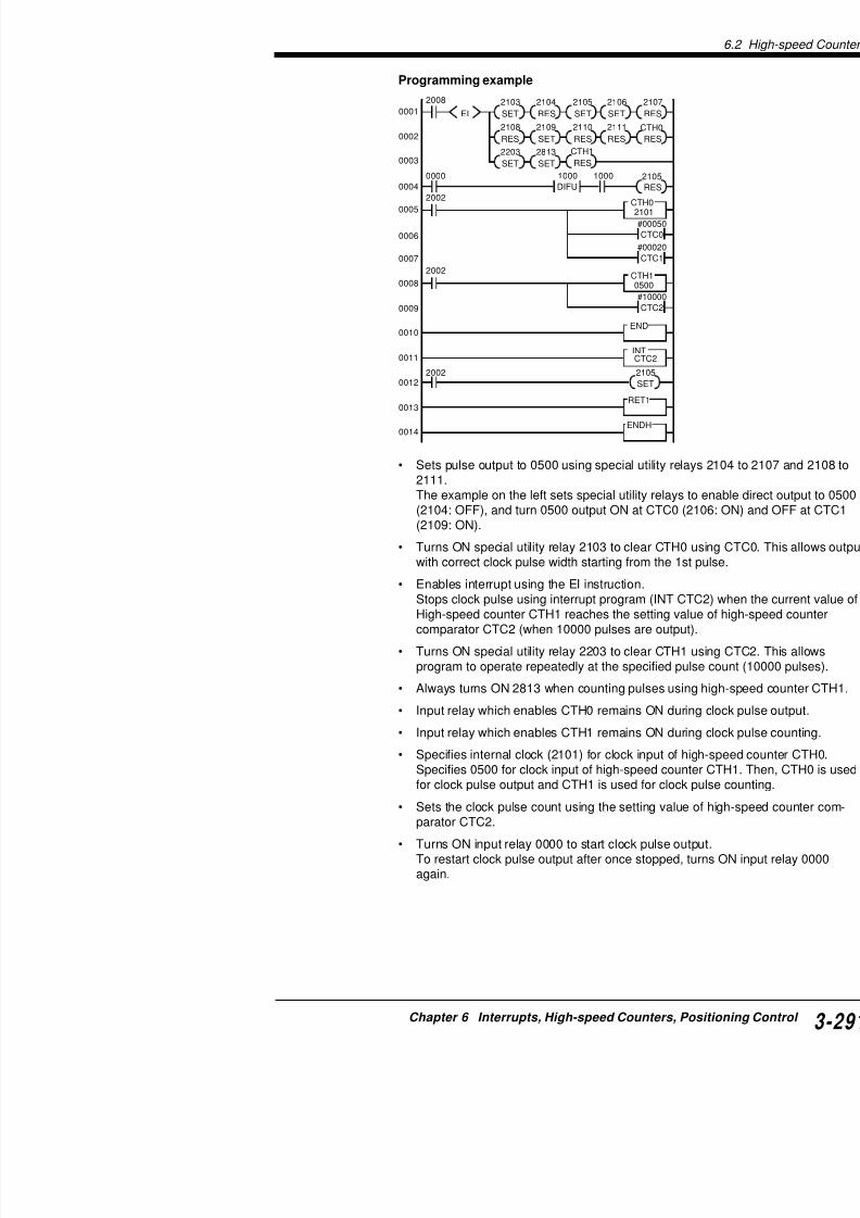
7/18/2019 Keyence Programming
http://slidepdf.com/reader/full/keyence-programming 315/392
p gStops clock pulse using interrupt program (INT CTHigh-speed counter CTH1 reaches the setting valu
comparator CTC2 (when 10000 pulses are output)
• Turns ON special utility relay 2203 to clear CTH1 uprogram to operate repeatedly at the specified puls
• Always turns ON 2813 when counting pulses using
• Input relay which enables CTH0 remains ON durin
• Input relay which enables CTH1 remains ON durin
6.2 High-speed Counters
KV-300
K V
- 1 0 / 8 0
Coding
Line No. Instruction Operand Line No. Instruction0000 LD 2008 0024 SET
0001 EI 0025 CON
0002 CON 0026 SET
0003 MPS 0027 CON
0004 SET 2103 0028 RES
0005 CON 0029 LD
0006 RES 2104 0030 DIFU
0007 CON 0031 CON
0008 SET 2105 0032 AND
0009 CON 0033 RES
0010 SET 2106 0034 LD
0011 CON 0035 CTH
0012 RES 2107 0036 CTC
0013 MRD 0037 CTC
0014 RES 2108 0038 LD0015 CON 0039 CTH
0016 SET 2109 0040 CTC
0017 CON 0041 END
0018 RES 2110 0042 INT
0019 CON 0043 LD
0020 RES 2111 0044 SET
0021 CON 0045 RETI
0022 RES CTH0 0046 ENDH0023 MPP
Special utility relays 2103 to 2111 can be set to turn ON or OFF instructions as well as SET and RES instructions. Example belowone program can be made shorter using LDA and STA instructio
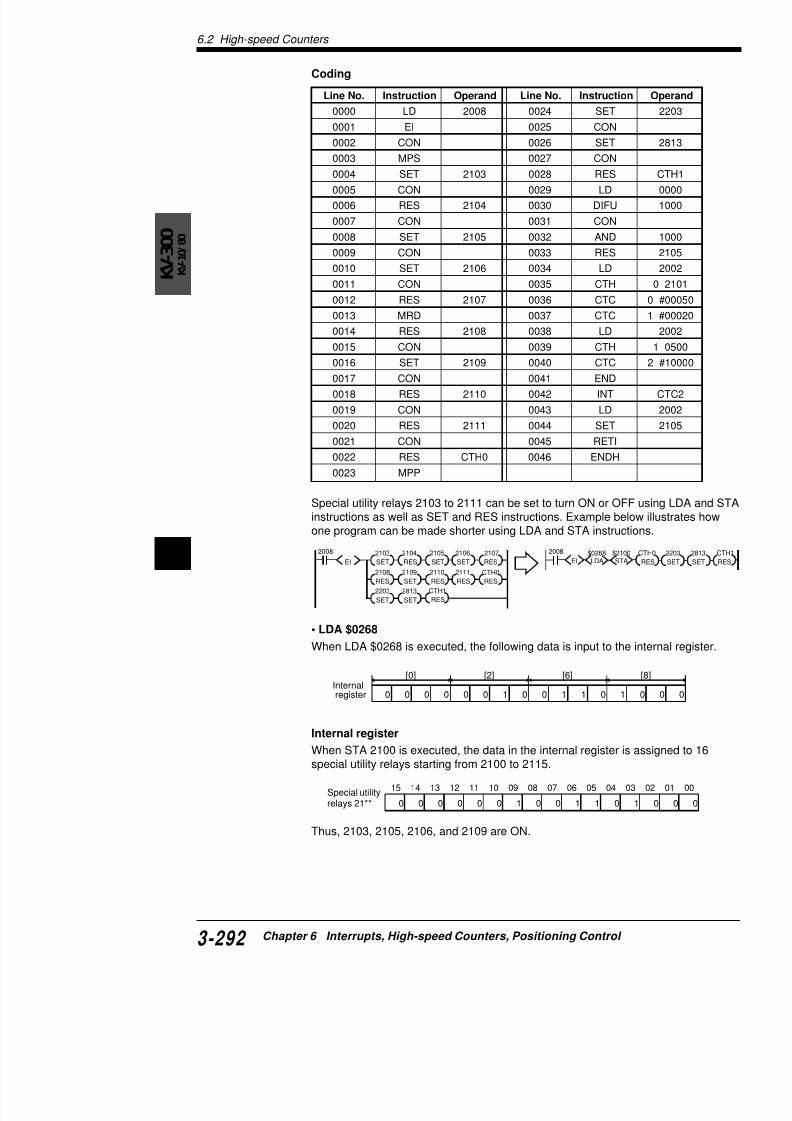
7/18/2019 Keyence Programming
http://slidepdf.com/reader/full/keyence-programming 316/392
6 2008
SET
2103 2104 2105 2106
RES SET SET RES
RES
2108 2109 2110 2111 CTH0
SET RES RES RES
2107
SET
2203 2813
SET
CTH1
RES
EI
2008
EI LDA STA$0268 $2100
Internal[0] [2] [6]
• LDA $0268
When LDA $0268 is executed, the following data is input to the in
COM00000001
0500050105020503
1112
7
89
10COM 20
24 VDC –
+KV-300
FG
Twisted pair cable
CW
CCW(rotadirec
Steppin
S t a r t
R e v e r s e
24 VDC
– +
0
fH
(DM0000)
fL(DM0001)
Frequency (Hz)
Accelerationrate
(DM0002)
10 msAccelerationchange time
Positioningpulse totalcount(DM0003)
Example of pulse output (Ramp-up/down control)
The following example performs ramp-up/down controparameters (DM0000 to DM0003).
Connection example
The following chart shows an operation example whennected to the stepping motor driver. See the stepping manual for details.Set the pulse input mode of the stepping motor driver

7/18/2019 Keyence Programming
http://slidepdf.com/reader/full/keyence-programming 317/392
Acceleration time Constantrate time
D
Setting parameters
DM0000: fH [Hz] (Run frequency) 153 Hz to 50000 fL.DM0001: fH [Hz] (Start frequency)DM0002: Acceleration rate [Hz/10 ms] (fH-fL) ÷ (AcDM0003: Positioning pulse count 65534 pulses ma
6.2 High-speed Counters
KV-300
K V
- 1 0 / 8 0
2002
INITIAL SETUP FOR HIGH-SPEED COUNTER/COMPARATOR
#00010CTC1
#65535CTC0
CTH0
2100
#65535CTC2
#65535CTC3
CTH1
0500
2008 #08000
DW
DM0000
#00700
DW
DM0001
#00400
DW
DM0002
#04000
DW
DM0003
(SET ) (SET )2813 2105
STARTS POSITIONING
0003 0000 1001
DIFU
1001
$0268
LDA
2100
STA
01
CALL (SET ) (RES )1200 CTH1
(RES )CTH0
(RES )EI
2105
0001
( )0502
EMERGENCY STOP
0003
(SET)2105
END
CTC0,CTC2,DM0011, CALCULATION SUBROUTINE
SBN
02
2002 #01000
LDA
#10000
MUL
DM0012
DIV
#00005
ADD
#00010
DIV
CTC0
STA
DM0010
STA
#00010
LDA
#10000
MUL
DM0010
DIV
#00005
ADD
#00010
DIV
DM0011
ADD
CTC2
STA
DM0011
STA
0001
0002
0003
0004
0005
0006
0007
0008
0009
0010
0011
0012
0013
0014
0015
0016
Generates cspeed count
Counts clocspeed count• CTC0: Pu
CTC1: Pu• CTC2: Fre
CTC3: Pocount
Sets parameDM0003).
Reverse out
Emergency Sets CTC0.Setting value 1 ÷ DM001
Sets CTC2.
Programming exmaple

7/18/2019 Keyence Programming
http://slidepdf.com/reader/full/keyence-programming 318/392
6
INITIALIZING SUBROUTINE
RET
SBN
01
DM0003
LDA
CTC3
STA
#00002
DIV
DM0004
STA
DM0001
LDA
DM0012
STA
#00000
DW
DM0011
2002 02
CALL
RET
0017
0018
0019
0020
• DM0010: P• DM0011: A
• DM0012: C• 1200: Acce
RET
0025
INTERRUPT ROUTINE FOR SPEED-UP/SLOW-DOWN
INT
CTC2
SPEED-UP
DM0012
LDA
DM0002
ADD
DM0012
STA
DM0000
CMP
1200 2011 03
CALL
2011 02
CALL
2011( )1201
2011 DM0003
LDA
DM0011
SUB
CTC2
STA
DM0011
STA
1201
(RES )1200
SPEED-UP
DM0012
LDA
DM0002
SUB
DM0012
STA
DM0001
CMP
1200 2011 02
CALL
2011 02
CALL
#65535
LDA
CTC2
STA
RETI
RETI
ENDH
INTERRUPT FOR PULSE STOP
INT
CTC3
2002(SET )2105
0026
0027
0028
0029
0030
0031
0032
0033
0034
0035
0036
0037
0038
0039
0040
0041

7/18/2019 Keyence Programming
http://slidepdf.com/reader/full/keyence-programming 319/392
6.3 Positioning Control
KV-300
K V
- 1 0 / 8 0
6
6.3 Positioning Control
6.3.1 Positioning Control (Ramp-up/down Control
Outline of positioning control
The KV-300 CPU outputs clock pulses, independent of scan timeoutput relay 0500 or 0501. When the clock pulse frequency, outpacceleration/deceleration time are set to the data memory addres
the KV-300 CPU automatically performs ramp-up/down control. Ocan be set within the range of 153 Hz to 50000 Hz.
With this function, ramp-up/down control over stepper motors and
(pulse input type) becomes possible.The following section describes setting and application of positioparameters.
Acceleration time Decelera
Frequency (Hz)
Operation
StartOutput pulse count
Clock pulse

7/18/2019 Keyence Programming
http://slidepdf.com/reader/full/keyence-programming 320/392
6
Motor driver
Rotation direction
Lo: CWHi : CCW
KV-300
0500
0501
05020503
Setting and application of parameters
This section describes how to set and apply paramete
Setting parameters
Set the parameters to the assigned data memory addpositioning control function, the special utility relays mThe following table shows the parameters and assigne
Note: Refer to the following expression to determine t
Output pulse count < (65535 x pulse change cycle [m[Hz])
DMNo. Parameter
DM9407 Set value error code Cis
X-axis DM9408 0500 Start frequency (Hz) 1
(0500) DM9409 0500 Run frequency (Hz) 1
DM9410 0500 Acceleration/deceleration 0time (ms)
DM9411 0500 Output pulse count 0(high-order 16 bits)
DM9412 0500 Output pulse count 0(low-order 16 bits)
Y-axis DM9413 0501 Start frequency (Hz) 1
(0501) DM9414 0501 Run frequency (Hz) 1
DM9415 0501 Acceleration/deceleration 0time (ms)
DM9416 0501 Output pulse count 0(high-order 16 bits)
DM9417 0501 Output pulse count 0
(low-order 16 bits)

7/18/2019 Keyence Programming
http://slidepdf.com/reader/full/keyence-programming 321/392
Pulse change cycle (∆t)
The pulse change cycle is the cycle in which the outpuchanged for acceleration or deceleration. The pulse cone of the following expressions, whichever produceswhen the start pulse is less than 500 Hz, the pulse chmore.
Pulse change cycle (∆t) [ms] = (acceleration time [ms]orP l h l (∆t) [ ] 1000 ( f
6.3 Positioning Control
KV-300
K V
- 1 0 / 8 0
6
Set value error code
Automatically writes an error code (11 to 17) into DM9407 when error is found at startup.
Corrective action for error code 16
Error code 16 is issued when the output pulse count during accetion time exceeds other values calculated from the preset parameTo recover from the error, the following corrective actions are ava• Change the run frequency and/ or the acceleration/ decelerat
to the following expression.
Corrective action for error code FFFF (-1)• Reduce run frequency and start frequency.• Reduce accelleration/ deccelleration time.
Code Error description Corrective actio
11 Start frequency is below allowable Adjust start frequrange. able range (153 t
12 Run frequency is below allowable Adjust run frequerange. able range (153 t
13 Run/start frequency exceeds allow- Adjust run/start f
able range. allowable range14 Start frequency is greater than run Reduce start freq
frequency. run frequency.
15 Acceleration/deceleration time Adjust acceleratiexceeds allowable range. to within allowab
16 Too many pulses are output during Change the paraacceleration/deceleration time.
17 Too few pulses are output during Set 2 or more asacceleration/deceleration time. pulse count.
FFFF Other calculation error Change the para
65535Run frequency
x Pulse change cycle x 655351000

7/18/2019 Keyence Programming
http://slidepdf.com/reader/full/keyence-programming 322/392
6 Start frequency (Hz)
Sets a start frequency (speed) to start the motor rotation smoothcontrol.
The KV-300 CPU outputs clock pulses at the specified freque
Run frequency (Hz)
Sets the motor frequency (speed) during positioning control. Theoutputs clock pulses at the specified frequency.
Acceleration/deceleration time (ms)
Sets the time required when the start frequency accelstartup. In the same manner, sets the deceleration tim300 CPU controls the clock pulse frequency from the frequency within the specified time. The pulse changetime is obtained from one of the following expressionssmaller solution. However, the pulse change cycle wh500 Hz becomes 14 ms or more.
Pulse change cycle (∆t) ms = (acceleration time ms +
orPulse change cycle (∆t) ms = 1000 ÷ (run frequency H
Output pulse count
Sets the positioning control rotation angle (moving disThe KV-300 CPU outputs as many clock pulses as spcount is greater than 65535, set the pulse count sepaand low-order 16 bits based on the following expressio
(Output pulse count) ÷ 65536 = A (solution) … B (r
A = Output pulse count (high-order 16 bits)B = Output pulse count (low-order 16 bits)
Note: When the specified output pulse count is insuffitarget value, the KV-300 CPU performs triangular con
The current pulse output value cannot be checked.
Procedure
0
Run frequency
Start frequency
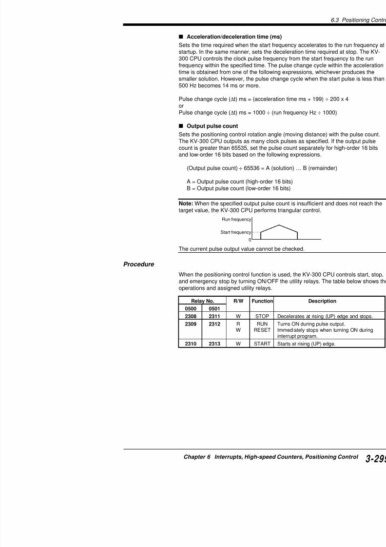
7/18/2019 Keyence Programming
http://slidepdf.com/reader/full/keyence-programming 323/392
When the positioning control function is used, the KV-
and emergency stop by turning ON/OFF the utility relaoperations and assigned utility relays.
Relay No. R/W Function D
0500 0501
2308 2311 W STOP Decelerates at
2309 2312 R RUN Turns ON durinW RESET Immediately sto
6.3 Positioning Control
KV-300
K V
- 1 0 / 8 0
6
DM9409
DM9408
0
DM9411
DM9412
DM9410DM9410
2310(START)
2309(RUN)
2308(STOP)
Operation chart (when 0500 is used)
Note 1: When special utility relay 2310 (2313) is turned ON at st
2309 (2312) turns ON and the clock pulse is output, assuming paare correct.
Note 2: If a parameter setting for the X-axis or Y-axis is incorrectnot turn ON and an error code is written into DM9407. Check theadjust the parameter setting.
Note 3: By resetting 2309 (2312) within the interrupt program, yoclock pulse immediately. You must reset 2309 within the interrupwise, the clock pulse is not stopped.
Note 4: Because the clock pulse is output under software controextended by 10 µs to 20 µs in the pulse change cycle. Test the cthe KV-300 system before using it in practical applications.
Examples of stepping motor control
Connection example
The following reference example shows how to connect the KV-3
DM9408: Start frequDM9409: Run frequDM9410: AcceleratiDM9411: Output pu
(high-ordeDM9412: Output pu
(low-order
When 2310 turns O
(rising [UP] edge is 2309 is ON during cpulse output is stopWhen turning ON 23decelerates and stodetected.)

7/18/2019 Keyence Programming
http://slidepdf.com/reader/full/keyence-programming 324/392
6
24 VDC –
+
E m e r g e n c y
s t o p
S t o
p
S t a
r t
e o o g e e e ce e a p e s o s o to co ect t e 3stepping motor driver. Refer to the stepping motor driver instructi
details.Set the pulse input mode for the stepping motor driver to "Pulse i
15000
80002000
3000
Ramp-up/down control
When start switch 0002 is turned ON, 0500 outputs 10following conditions: start frequency 1 kHz, run frequedeceleration time 3 s.Turn ON 0001 to decelerate and stop pulse output. Woutput is immediately stopped.
Application example of stepping motor control
Assume a program that can be controlled both automaIn automatic mode, the system runs as shown in the cON.
0002DW DW DW DW DW
2008
EI
#01000 #05000 #03000 #00001 #34464 2310
0001 2308
END
INT0000
2002
RES
2309
RET1
ENDH
DM9408 DM9409 DM9410 DM9411 DM9412
0001
0002
0003
0004
0005
0006
0007
0008
EnThop
Se
staDe
Exeinte

7/18/2019 Keyence Programming
http://slidepdf.com/reader/full/keyence-programming 325/392
15000
In manual mode, the system goes forward while 00080009 is ON. It returns to the origin when 0007 turns OA pulse is output from 0500. Reverse the rotation direThe system is equipped with an origin sensor (0002), rearward end limit (0004).
6.3 Positioning Control
KV-300
K V
- 1 0 / 8 0
6
0001
0002
0003
0004
0005
0006
0007
0008
0009
0010
0011
0012
0013
0014
0015
0016
0017
STEPPING MOTOR CONTROL PROGRAM (ORIGIN, FORWARD, REVERSE LIMITS)
SPECIFICATION
PULUSE OUT==500 FOR/REV=502 ORIGIN=0002 FOR/END=0006 FOR/END=0004
MANUAL SW: FORWARD=0008 REVERSE=0009 ORIGIN SW=0007
AUTO OPERATION START=0000
ENABLES INTERRUPT & RESETS ORIGIN POSITIONING FRAG
MANUAL SWITCHES: FORWARD=0008 REVERSE=0009
LIMIT SWITCHES
* * * * * * * * * * * * * * * * * * * * * * * * * * ORIGIN * * * * * * * * * * * * * * * * * * * * * * * * * * * *
2008 1200
(RES) < EI >
0008 0009 2309 00060502(SET) DIFU
1100
0009 0008 2309 00040502
(RES) DIFU1101
1100
1101
< DW > < DW > < DW > < DW > < DW >1103
DIFU
#00600
DM9408
#04000
DM9409
#00100
DM9410
#00001
DM9411
#00000
DM9412
0008 0009 1105
DIFU
0007 1205
DIFU
Program example
Sets start frand accelerStart frequeRun frequenAcceleration
100 msOutput puls
To return to
forward andwhen origin
For forwardparameters
Start frequeRun frequenAcceleration/Output puls
For rearwar
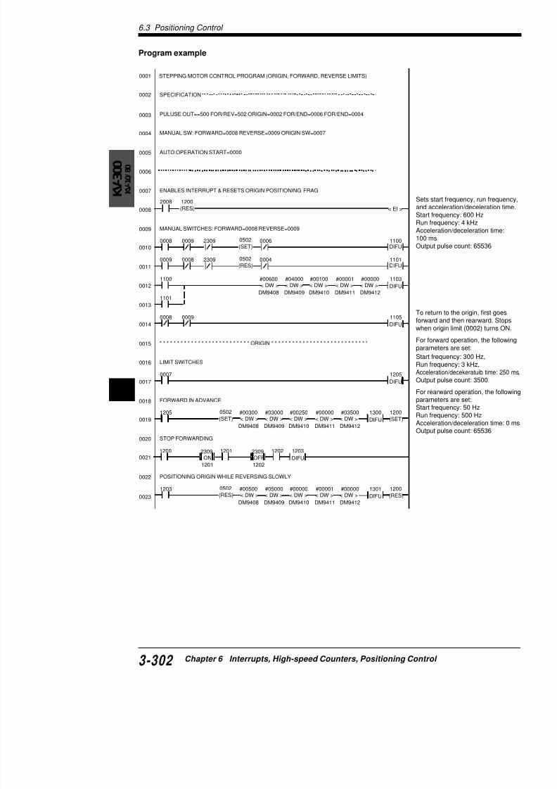
7/18/2019 Keyence Programming
http://slidepdf.com/reader/full/keyence-programming 326/392
60018
0019
0020
0021
0022
FORWARD IN ADVANCE
STOP FORWARDING
POSITIONING ORIGIN WHILE REVERSING SLOWLY
1205< DW > < DW > < DW > < DW > < DW >
1300
DIFU
#00300
DM9408
#03000
DM9409
#00250
DM9410
#00000
DM9411
#03500
DM9412
0502
(SET)1200
(SET)
1203
DIFU
1200 1201 12022309ON
2309OFF
1201 1202
parameters
Start frequeRun frequenAccelerationOutput puls
0025
0026
0027
0028
0029
0030
0031
0032
0033
0034
0035
0036
0037
0038
0039
0040
0041
0042
SLOW DOWN & STOP (MANUAL/AUTO)
MOVES TO NEXT STAGE AFTER MOTOR STOPS
* * * * * * * * * * * * * * * * * * * * * * * * AUTO OPERATION CH0 * * * * * * * * * * * * * * * * * * * *
2008 1400
(SET)
2308 1401
(RES)
T003 2309
1407
1400JMP
1502DIFU
1403STG
1406
(RES)#00005T003
1407
T002 2309
1406
1403
JMP
1501
DIFU1402
STG
1405
(RES)#00005
T002
1406
T001 2309
1405
1402
JMP
1500
DIFU1401
STG
1407
(RES)#00010
T001
1405
0000 1401
JMP1400
STG
1300 00062310
( )
1301 0004
1103
1506 2308
0006 0009 2308
( )
0004 0008
1105
DIFU1408 1402
(RES)
1403
(RES)1408
STAGE INSTRUCTION START
AUTO START (OPERATES DURING 0000 IS TURNED ON)
1400
(SET)
0024 STARTS MOTOR
Instdec
Crewithpro
Set(1) RunAccOut(2) RunAccOut

7/18/2019 Keyence Programming
http://slidepdf.com/reader/full/keyence-programming 327/392
0043
0044
0045
0046
0047 STARTS MOTOR
1502< DW > < DW > < DW > < DW > < DW >#00300
DM9408
#15000
DM9409
#00250
DM9410
#00000
DM9411
#17500
DM9412
0502
(RES)1505
DIFU
1501< DW > < DW > < DW > < DW > < DW >#00300
DM9408
#02000
DM9409
#00250
DM9410
#00000
DM9411
#02500
DM9412
0502
(SET)1504
DIFU
1500< DW > < DW > < DW > < DW > < DW >#00300
DM9408
#08000
DM9409
#00150
DM9410
#00000
DM9411
#15000
DM9412
0502
(SET)1503
DIFU
AUTO OPERATION PARAMETER SET
1506
Out
(3) RunAccOut
Stopro
6.3 Positioning Control
KV-300
K V
- 1 0 / 8 0
6

7/18/2019 Keyence Programming
http://slidepdf.com/reader/full/keyence-programming 328/392
Chapter 7
Serial Communication
The KV Series can be connected to an external device
to establish communication.This chapter describes communications specificationsSeries to external devices, and how to perform comm
7.1 Communications Specifications ......7.1.1 Communications Specification ....................7.1.2 Connection with the KV Unit .......................7.1.3 Connecting the KV-300 CPU to a Personal C
7.2 Serial Communication .......................7.2.1 Command Transmission Procedure............7.2.2 Format of Commands/Responses ..............7.2.3 Communication Command/Response List ..7.2.4 Setting Communication Commands and Re7.2.5 Other Response Codes...............................7.2.6 Error Code List ............................................7.2.7 Example Program .......................................
7 3 L di T t D t
7/18/2019 Keyence Programming
http://slidepdf.com/reader/full/keyence-programming 329/392
7.3 Loading Text Data ..............................
7.3.1 Receiving Text Data....................................7.3.2 Transmitting Text Data................................7.3.3 Sample Program .........................................
7.4 ASCII Code List ..................................
7.1 Communications Specifications
7.1 Communications Specifications
This section describes the specifications for the RS-232C interfation between the KV and external devices.
7.1.1 Communications Specification
The communications specification of the KV is summarized in thecommunications parameters of the personal computer by referrin
Communications parameters
Note 1: Be sure to specify the same communication parametersexternal devices to be connected. Communication will fail if differused.Note 2: Refer to the instruction manual supplied with each devicecommunications parameters on the device.
7.1.2 Connection with the KV Unit
Use the special connection cable (Straight cable: OP-26487, Rev96607) and a 25-pin D-sub connector (OP-26485) to connect theconnector of the external device.
Duplex Full
Synchronization Start/stop
Data format ASCII
Baud rate 9,600 bps
Data length 8 bits
Parity check Even
Stop bit length 1 bitDelimiter CR
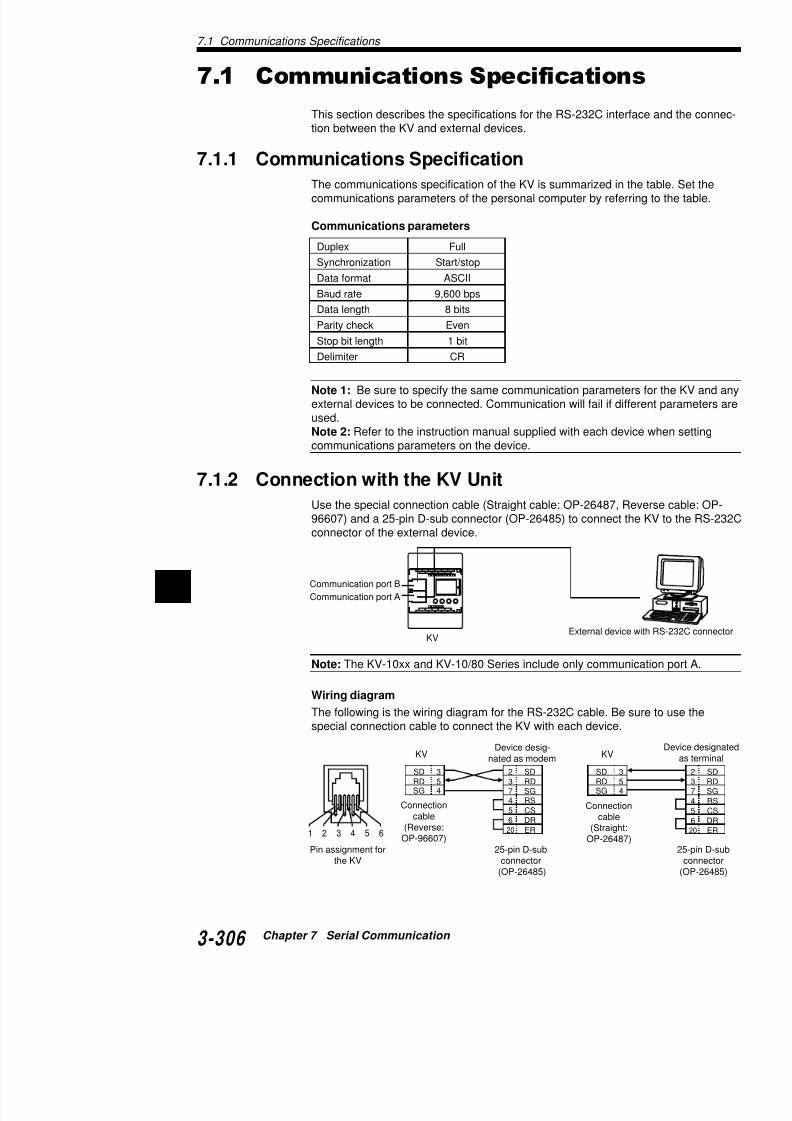
7/18/2019 Keyence Programming
http://slidepdf.com/reader/full/keyence-programming 330/392
7
Note: The KV-10xx and KV-10/80 Series include only communic
External device w
Communication port A
Communication port B
KV
7.1
7.1.3 Connecting the KV-300 CPU to a Pers
Connect the KV-300 CPU to the RS-232C port of the supplied connecting cable (OP-226486/OP-26487).
Recommended pin assignments for the RS-232C combelow. When connecting the KV-300 CPU, use only th
Standard cable (OP-26486 + OP-26487)
KV-300
Connecting cable
Standard cable:OP-26486
9-pin D-SUB fem
connector: OP-2
KV-300
SD
RD
SG
3
5
4
2
3
4
56
20
7
SD
RD
SG
SD
RD
RS
CSDR
ER
SG5432
Pin assignments forthe KV-300 CPU
DCE
3
5
4
2
34
5
6
7
8
SD
RD
SG
ModularConnector
9-pin D-sub connecto

7/18/2019 Keyence Programming
http://slidepdf.com/reader/full/keyence-programming 331/392
7.2 Serial Communication
7.2 Serial Communication
When the KV is connected to a personal computer, the current vof timers/counters or contents of data memories in the KV can bemodified on the computer.
7.2.1 Command Transmission Procedure
Commands are transmitted from a personal computer to the KV
Transmitting a break signal
A break signal is used to initialize the communication buffer and the KV. It is necessary to transmit a break signal of 100 ms or lonbefore starting communication. Another break signal is unnecesscommunication is established.
Transmits a command
Transmits communicationsstart command (CR)
Initialize the communication buffebaud rate setting of the KV.
Start communications with the KV
Transmit a command which instru
KV to perform the required operat
Transmits communicationsend command (CQ)
End communications with the KV.
Receive and check the response ttransmitted command.
Transmits a break signal
Receiving a response
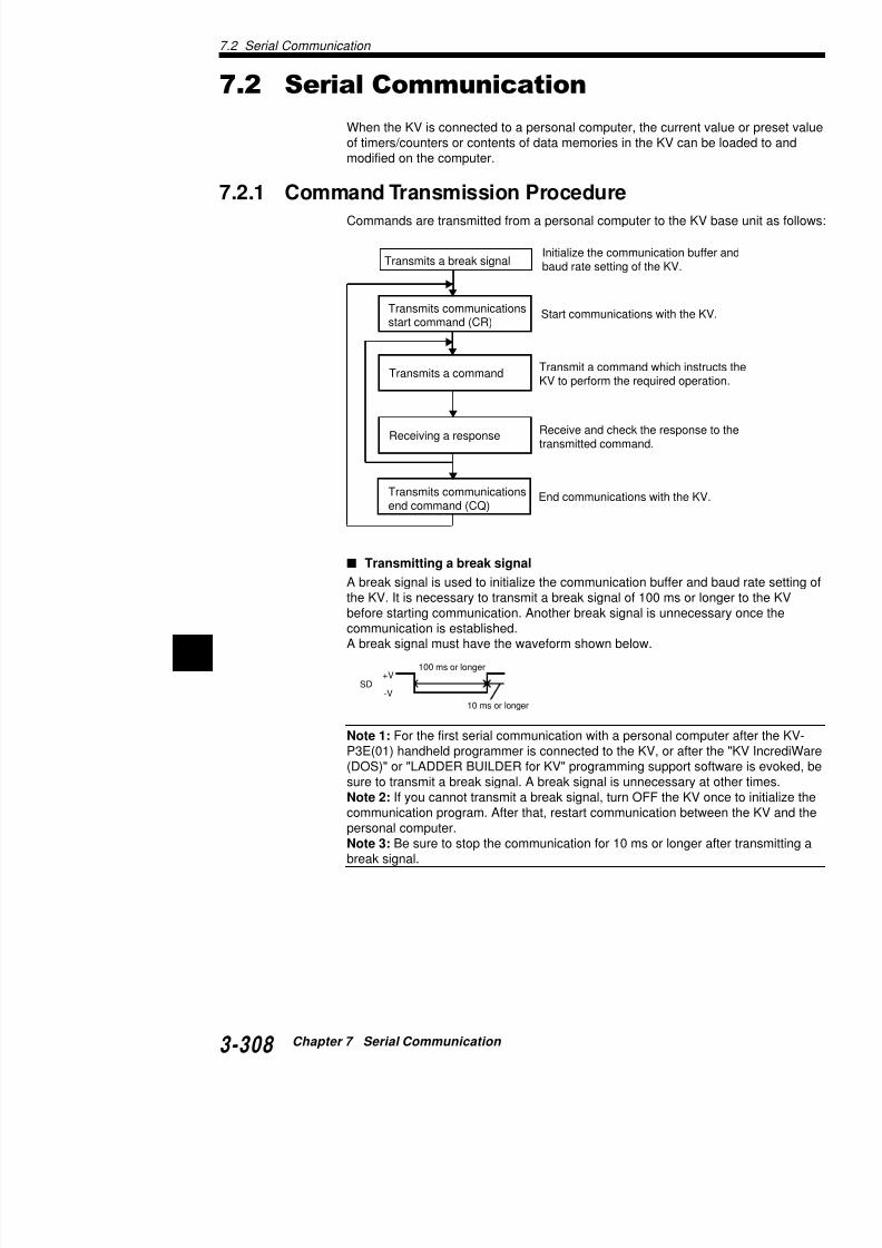
7/18/2019 Keyence Programming
http://slidepdf.com/reader/full/keyence-programming 332/392
7 A break signal must have the waveform shown below.
Note 1: For the first serial communication with a personal compuP3E(01) handheld programmer is connected to the KV, or after th(DOS)" "LADDER BUILDER f KV" i f
10 ms or longer
100 ms or longer+V
-VSD
Command/response format
"Command" and "response" in communications betwe
computer are defined as follows:
Command: Message transmitted from personal comp
Response: Answer to the command (message from K
When a personal computer transmits a command to thsends back a response to the personal computer.When creating a program to control the KV using a pethat the response is checked before the next comman
7.2.2 Format of Commands/Responses
The formats of commands and responses are as follow
Command format
Use the following format to transmit commands from t
KV. [CR] is a delimiter. The KV ignores [LF] and recog[LF] as the next command.
Response format
The KV sends back a response to the received comm
When creating a program using a personal computer, computer can process the response in this format.
Command
Response
Or
CR
CR LFCommand
CR
LF

7/18/2019 Keyence Programming
http://slidepdf.com/reader/full/keyence-programming 333/392
7.2 Serial Communication
7.2.3 Communication Command/Response List
The following list shows the commands and responses used in stion. "_" in the list represents a space.
noitcnuF dnammoC esnopseR eD
.noitacinummocstratS RC CC
.noitacinummocsdnE QC FC
.edomsegnahC nM KOmMARGORP:0=n
edomNUR:1
.rorresraelC RE KO
.rorreCLPskcehC E? dd :00(edocrorrE=dd
.edomCLPtnerrucskcehC M? fomMARGORP:0=f
edomNUR:1
retnuoC nnnC _ DR
ddddd,ddddd,f↑↑
)eulavteserP()eulavtnerruC(
1,FFOtcatnoC:0=f6ot00000=dddddd.oNretnuoC=nnn / n
deeps-hgiHHTCretnuoc
nHTC _ DR
deeps-hgiHretnuoc
CTCrotarapmocnCTC _ DR
sdaeR remiT nnnT _ DR ddddd,ddddd,f ↑↑)eulavteserP()eulavtnerruC(
1FFOtcatnoC:0=f 6ot00000=dddddd.oNremiT=nnn
remmirtlatigiD TA _ DR00000 _ 00000 _ ddddd _ ddddd
↑↑)1remmirT()0remmirT(
6ot00000=ddddddseulavteserpsdaeR
tcatnocyaleR nnnnn _ DR f 1,FFOtcatnoC:0=f
yromemataD nnnnMD _ DR
ddddd6ot00000=dddddd
.oNMD=nnnnatadyraropmeT
yromem nnMT _ DRtnerrucretnuoC
eulavddddd _ nnnC _ RW
KOetnuoc / remiT=nnn / n
00000=dddddd.oNtnerrucremiT
eulavddddd _ nnnT _ RW
tnerrucHTCeulav
ddddd _ nHTC _ RW
setirWteserpretnuoC
eulav .2 ddddd _ nnnC _ SW
KOetnuoc / remiT=nnn / nteserpremiT
dddddnnnTSW

7/18/2019 Keyence Programming
http://slidepdf.com/reader/full/keyence-programming 334/392
7KO
00000=dddddd.oNeulav .2 ddddd _ nnnT _ SW
teserpCTCeulav .2 ddddd _ nCTC _ SW
yromemataD ddddd _ nnnnMD _ RW
KO6ot00000=dddddd
.oNMD=nnnn,nnatadyraropmeTyromem
ddddd _ nnMT _ RW
yaleR nnnnn _ TS
KO.oNyaleR=nnnn
retnuoc / remiT=nnnNOsecroF tcatnocretnuoC nnnC _ TS
ttiT TTS
7.2.4 Setting Communication Commands a
CommandsThis section describes the command settings and resproperly processed."_" represents a space.Refer to "7.2.5 Other Response Codes" (p. 3-315) for conditions.
Communications start command
Transmit a communications start command to start coOther commands can be transmitted after the proper rKV.
Note: Other commands cannot be used unless a [CRcommand is transmitted first.
Starts communications between the KV and a person
Command: CRResponse: CC
Communications end command
Ends communications between the KV and a persona
Command: CQResponse: CF
Mode change commandSelects the mode between PROGRAM and RUN.
Command: Mn [n=0; PROGRAM mode, n=1; RResponse: OK
Error clear command
Clears error messages on KV.
Command: ER

7/18/2019 Keyence Programming
http://slidepdf.com/reader/full/keyence-programming 335/392
Response: OK
Checking KV PLC error
Checks errors or faults in the KV. The description of therror code.
"7.2.6 Error Code List" (p. 3-316).
Command: ?EResponse dd
7.2 Serial Communication
Reading counter
Reads the contact ON/OFF status, or the current and preset valu
counter/up-down counter.Command: RD_Cnnn
Counter No.Response: f,ddddd,ddddd
[Preset value of the counter (000decimal)][Current value of the counter (00decimal)]0: Contact is OFF., 1: Contact is
Reading high-speed counter CTH
Reads the contact ON/OFF status, or the current and preset valuhigh-speed counter CTH.
Command: RD_CTHnHigh-speed counter No. (0 or 1)
Response: f,ddddd,dddddPreset value of CTH (00000 to 6
Current value of CTH (00000 to 0: Contact is OFF., 1: Contact is
Reading high-speed counter comparator CTC
Reads the contact ON/OFF status, or the current and preset valuhigh-speed counter comparator CTC.
Command: RD_CTCnHigh-speed counter comparator
Response: f,ddddd,dddddPreset value of CTC (00000 to 6Current value of CTC (00000 to 0: Contact is OFF., 1: Contact is
Reading timer
Reads the contact ON/OFF status, or the current and preset valutimer.
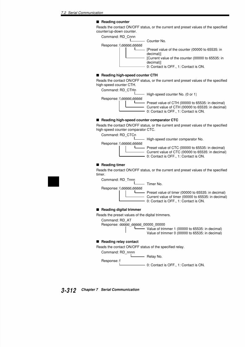
7/18/2019 Keyence Programming
http://slidepdf.com/reader/full/keyence-programming 336/392
7 Command: RD_TnnnTimer No.
Response: f,ddddd,dddddPreset value of timer (00000 to 6Current value of timer (00000 to 0: Contact is OFF., 1: Contact is
Reading digital trimmer
Reading DM
Reads the contents of the specified data memory.
Command: RD_DMnnnnData memory No.
Response: dddddData in the specified d65535: in decimal)
Reading TM
Reads the contents of the specified temporary data m
Command: RD_TMnnTemporary data mem
Response: dddddData in the specified t(00000 to 65535: in d
Writing current value of counter
Changes the current value of the specified counter or
Command: WR_Cnn_ddddd
New current value (00Counter No.Response: OK
Writing current value of timer
Changes the current value of the specified timer.
Command: WR_Tnnn_dddddNew current value (00Timer No.
Response: OK
Writing current value of high-speed counter CT
Changes the current value of the specified high-speed
Command: WR_CTHn_dddddNew current value (00High-speed counter N
Response: OK

7/18/2019 Keyence Programming
http://slidepdf.com/reader/full/keyence-programming 337/392
Writing preset value of counter
Changes the preset value of the specified counter or u
Command: WS_Cnnn_dddddNew preset value (00Counter No.
Response: OK
Note: Executing this command changes the program in the
7.2 Serial Communication
Writing preset value of high-speed counter comparator C
Changes the preset value of the specified high-speed counter co
Command: WS_CTCn_dddddNew preset value (00000 to 6High-speed counter compara
Response: OK
Writing into DM
Writes data into the specified data memory.
Command: WR_DMnnnn_ddddd
New current value (00000 to Data memory No.
Response: OK
Writing into TM
Writes data into the specified temporary data memory. TM30 andonly memories, so values cannot be written to them.
Command: WR_TMnn_ddddd
New current value (00000 to Temporary data memory No. Response: OK
Forcing relay ON
Forces the contact of the specified relay to ON.
Command: ST_nnnnnRelay No.
Response: OK
Forcing counter contact ON
Forces the contact of the specified counter to ON.
Command: ST_CnnnCounter No.
Response: OK
Forcing timer contact ON

7/18/2019 Keyence Programming
http://slidepdf.com/reader/full/keyence-programming 338/392
7 Forces the contact of the specified timer to ON.
Command: ST_TnnnTimer No.
Response: OK
Forcing relay OFF
Forces the contact of the specified relay to OFF.
Forcing CTC contact OFF
Forces the contact of the specified high-speed counte
Command: RS_CTCnHigh-speed counter c
Response: OK
Note 1: Input relays cannot be forced ON/OFF. (Exce2301 is ON.)Note 2: "_" in commands and responses represents a
7.2.5 Other Response CodesIf the command from a computer is an unspecified onethe KV sends back an appropriate response code for
Responsecode
Description Cause
• Undefined relay, counter,timer, DM, CTH, or CTC
number was specified.
• Counter, timer, CTH, orCTC number, unused in aprogram was specified.
• Undefined command wastransmitted.
• Incorrect command wasspecified.
• Command other than "CR"was transmitted before thecommunications path wasestablished.
E0
E1
E2
Relay No.error
Commanderror
Programunregistered
When the KV has no programstored, "M1" was transmittedor reading of timer/countercontent was attempted.
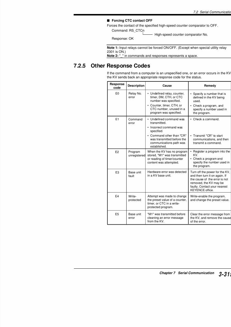
7/18/2019 Keyence Programming
http://slidepdf.com/reader/full/keyence-programming 339/392
E3
E4
Base unitfault
Write-protected
Hardware error was detectedin a KV base unit.
Attempt was made to changethe preset value of a counter
7.2 Serial Communication
7
Subroutines are nested to four levelsor more.
FOR/NEXT instructions are nested to
eight levels or more.Five levels or more of interruptsoccurred simultaneously.
MPS/MPP instructions are nested toeight levels or more.
Content in RAM was erased. All datain data memory and current values ofcounters in the KV were cleared.
Scan time exceeds 300 ms.
Attempt was made to operate a KVbase unit which has no programsstored.
Hardware error was detected in a KVbase unit.
Error code Description Cause Remedy
00 No error
10 CALL nest error
11 FOR nest error
12 INT nest error
13 MPS nest error
20 Memory error
30 Scan timer error
40 NO PROGRAM
50 SND/RTN failure
51 Division by zero52 Address error
53 Invalid instruction
54 Watchdog timer error
7.2.6 Error Code List
When a "Checking KV PLC error" command (?E) is transmitted, the error code. The following list shows the description, cause, aerror code.
These errors mayprogram is execu
Check the progra
particular attentiosubroutines and tand restore the p
Turn the KV off oRegister data from
Check the progra
• Be sure that therrepetition using t
• Be sure that an iexecuted at a hig
Write a program
Turn off the powethen turn it on agthe error is not rebe faulty. ContacKEYENCE office
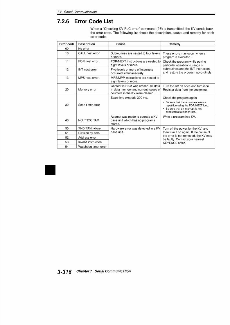
7/18/2019 Keyence Programming
http://slidepdf.com/reader/full/keyence-programming 340/392
7
7.2.7 Example Program
Typical program for communications between the KV IBM PC-AT & compatible computers using BASIC)
‘
‘Language Microsoft BASIC Version 7.0
‘
‘ *****I/OAddress (RS-232C Port-1)*****
‘Port-1&H3F*
‘Port-2&H2F*
‘
PortCtrl%=&H3FB’COM1
Port1Modem%=&H3FC’MODEMCtrlPortBpsLow%=&H3F8’BitrateLow
PortBpsHigh%=&H3F9’BitrateHigh
‘*****ControlCode*****
Port1CtrlCode1%=&H5B’Break&8bitEven1Stopbit
Port1CtrlCode2%=&H1B’8bitEven1Stopbit
‘*****InitializesRS-232C*****
OPEN"COM1:9600,N,8,1"FORRANDOMAS#1'
‘*****RS-232CPortInit*****
OUTPortCtrl %,Port1CtrlCode1%’Start transmitting a br
SLEEP1’wait 1 sec.
OUTPortCtrl%,Port1CtrlCode2%’Ends transmitting a brea
‘
‘-*-*-*-*-*-*-*-*-*-*-*-*-*-*-*-*-*-*-*-*-*-*-*-*-*-*
‘’’’’’’’’’’’*****DebugPrint*****
‘’’’’’’’’’’status=INP(&H3FE):PRINT"ModemStatus1";statu
‘’’’’’’’’’’status=INP(&H3FD):PRINT"LineStatus1";statu
‘’’’’’’’’’’’
‘’’’’’’’’’’’*****SelfInit.*****
‘’’’’’’’’’’linectrl=INP(PortCtrl%)’ReadLine-Control-R
‘’’’’’’’’’’linectrl=linectrlOR&H80'
‘’’’’’’’’’’OUTPortCtrl%,linectrl’DLAB=ON
‘’’’’’’’’’’
‘’’’’’’’’’’OUTPortBpsLow%,12’SetBitRate(9600BPS)‘’’’’’’’’’’OUTPortBpsHigh%,0'
‘’’’’’’’’’’
‘’’’’’’’’’’linectrl=linectrlAND&H7F’DLAB=OFF
‘’’’’’’’’’’OUTPortCtrl%,linectrl
‘’’’’’’’’’’’
‘’’’’’’’’’’’*****CtrlLine*****
‘’’’’’’’’’’OUTPort1Modem%,&HB’RTS,DTRON !!
‘’’’’’’’’’’’
‘’’’’’’’’’’’*****DebugPrint*****
‘’’’’’’’’’’status=INP(&H3FE):PRINT"ModemStatus2";statu
‘’’’’’’’’’’status=INP(&H3FD):PRINT"LineStatus2";statu
‘ * * * * * * * * * * * * * * * * * * * * * * * * * *
Note: No limitations
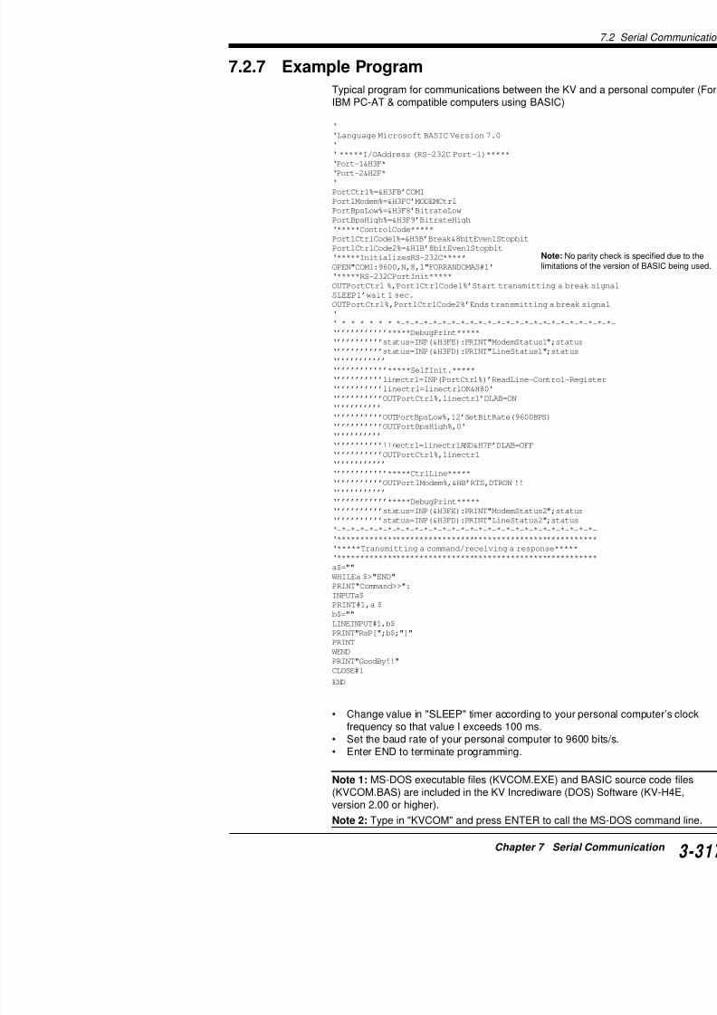
7/18/2019 Keyence Programming
http://slidepdf.com/reader/full/keyence-programming 341/392
‘-*-*-*-*-*-*-*-*-*-*-*-*-*-*-*-*-*-*-*-*-*-*-*-*-*-*‘****************************************************
‘*****Transmitting a command/receiving a response*****
‘****************************************************
a$=""
WHILEa $>"END"
PRINT"Command>>":
INPUTa$
PRINT#1,a $
b$=""
7.3 Loading Text Data
7
7.3 Loading Text Data
The KV can be connected to equipment having an RS-232C porttext data (less than 100 bytes) as a batch into its data memories.Loaded data can be modified and incorporated into a program.
7.3.1 Receiving Text Data
The KV can write up to 100 bytes of text data sandwiched betweinto internal data memories (DM1000 to DM1099 with communic
DM1200 to DM1299 with communication port B), one byte per daASCII code.
Communications data format
Note that each text data must include STX (02H) in the 1st byte f(100 bytes max.) and end with ETX (03H) in the last byte as show
Internal data memory
The KV writes received text data into its data memories (DM1000communication port A, DM1200 to 1299 with communication portdata memory in ASCII code.
The KV writes "00" into the high-order 8 bits and text data in ASClow-order 8 bits of the data memory.
STX
1st byte Last byte
Text data (less than 100 bytes) ETX
ataDyromem
WENVK
ATROP 0001MD 1001MD 2001MD t3001MDBTROP 0021MD 1021MD 2021MD t3021MD
003-VK08/01-VK
0029MD 1029MD 2029MD t3029MD
.oNataD tnuocetyB 1ataD 2ataD ot3ataD
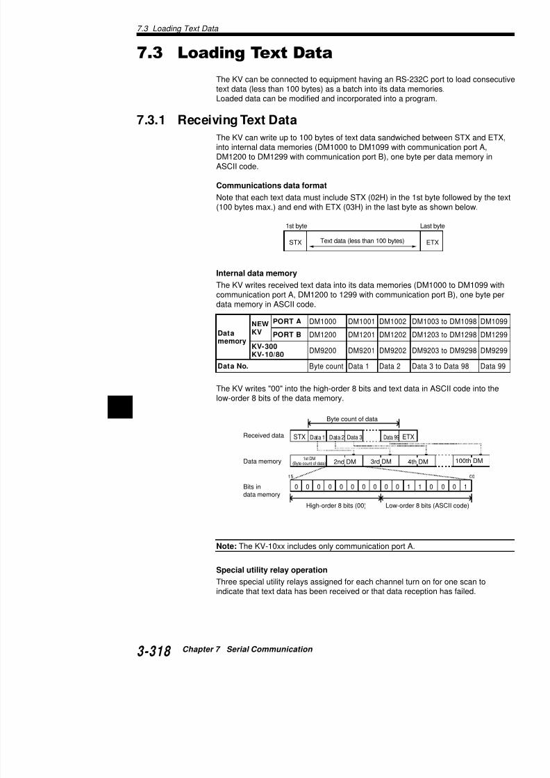
7/18/2019 Keyence Programming
http://slidepdf.com/reader/full/keyence-programming 342/392
7
Received data
Byte count of data
Data 1 Data 2 Data 3 Data 99
1st DM(Byte count of data)Data memory 2nd DM 3rd DM 4th DM
STX
15
ETX
Note 1: Be sure to transmit a break signal for the first
personal computer after the KV-P3E(01) handheld proKV, or after the "KV IncrediWare (DOS)" or "LADDERming support software is evoked.A break signal initializes the communication setting foa break signal, turn the KV OFF once to initialize the cwill not receive text data unless its communication set
Note 2: If [ETX] exists at some point in the text data, t[ETX] into the data memory. The data after [ETX] is no
Note 3: If KV receives text data while special utility rereceived data is not written into the data memory. In th2802 (2807)*2 turns ON for one scan.
Note 4: When parity errors or other errors occur durinreceived data is not written into the data memory. In th2802 (2807) and 2803 (2808)*3 turn ON for one scan.
Note 5: The KV-10xx includes only communication p
*1: 2804 with KV-300/10/80 *2: 2805 with KV-300/10/80 *3
7.3.2 Transmitting Text Data
The KV transmits text data written into its data memorcommunication port A, DM1300 to DM1399 for commdata memory in ASCII code.
Transmission data format and internal data memo
When transmitting data from the KV, write the data intfollowing format
.oNyaleR)ATROP(
.oNyaleR)BTROP(
.oNyaleR)08/01/003-VK(
1082 6082 4082 snruTebsah
2082 7082 5082snruT
ebsahehwro
3082 8082 6082snruT
tpecer

7/18/2019 Keyence Programming
http://slidepdf.com/reader/full/keyence-programming 343/392
following format.
ataDyromem
ATROP 0011MD 1011MD 2011MD D
BTROP 0031MD 1031MD 2031MD D
/003-VK08/01
0039MD 1039MD 2039MD D
.oNataD tnuocetyB 1ataD 2ataD D
7.3 Loading Text Data
7
Special utility relay operation
Two special utility relays are assigned for each channel for data t
data or a break signal is transmitted when the respective relay is
Note 1: Be sure to transmit a break signal for the first serial compersonal computer after the KV-P3E(01) handheld programmer iKV, or after the "KV IncrediWare (DOS)" or "LADDER BUILDER ming support software is evoked.A break signal initializes the communication setting for the KV. If a break signal, turn the KV OFF once to initialize the communicaThe KV will not transmit/receive text data unless its communicatiinitialized.
Note 2: Turn ON special utility relay 2804 (2809) (SET 2804 [280
data. Special utility relay 2804 (2809)*1 remains ON during text dand automatically turns OFF when the transmission completes.To forcefully stop the text data transmission, turn OFF special uti(2809) (RES 2804 [2809])*1.
Note 3: A break signal is transmitted while special utility relay 28Use the SET-RES instruction pair or OUT-OUB instruction pair tosignal. The communication program of the destination KV is initiasignal has been transmitted.
*1: 2807 with KV-300/10/80 *2: 2803 with KV-300/10/80
7.3.3 Sample Program
The following is the sample program to transmit/receive text datation port A on the KV basic unit.
Data to be transmitted: KEYENCETransmission header: STXTransmission delimiter: ETX
Length of received data: Fixed to 7 bytes
.oNyaleR)AtroP(
.oNyaleR)BtroP(
.oNyaleR)08/01/003-VK(
cseD
4082 9082 7082 snartspots / stratS
S:FFO,tratS:NO
0082 5082 3082 snartspots / stratS
S:FFO,tratS:NO

7/18/2019 Keyence Programming
http://slidepdf.com/reader/full/keyence-programming 344/392
7
T000
2800
2008 2800
#00010 T000
0001
0002
0003
Sends break signal (1 sec.).
One scan ON
Break signal
Whentransone sscan
Length of received data: Fixed to 7 bytes
0
01
2
3
4
5
6
7
8
9A
B
C
D
1 2 3 4 5 6
High-order 4 bits
Low-order4bits
7.4 ASCII Code List
The following are the ASCII code characters used for

7/18/2019 Keyence Programming
http://slidepdf.com/reader/full/keyence-programming 345/392
E
F
Characters in the shaded area can be used for data tr[STX], [ETX], [LF], and [CR] are used as data delimite
7.4 ASCII Code List
7

7/18/2019 Keyence Programming
http://slidepdf.com/reader/full/keyence-programming 346/392
7
Chapter 8
Programming Examples
This chapter describes the typical programming examSeries. These programs can be used for Visual KV Se
to the I/O addressing compatibility before use.
8.1 List ............................................................
8.2 Details ......................................................
8.2.1 Reference Program Examples ....................

7/18/2019 Keyence Programming
http://slidepdf.com/reader/full/keyence-programming 347/392
8.1 List
8.1 List
Instruction Program title
TMR, TMH, TMS [Timers] One-shot circuit
Off-delay circuit
On-delay circuit
Flicker circuit
C [Counter] Accumulator timer
Large capacity counterMulti-level Up/Down counter
Counter multi-level setting
DIFU, DIFD One-shot circuit
KEEP Detection of packs on conveyor
SFT Alternating circuit
Repeat shift circuit
Asynchronous shift register
Resetting internal utility relays
HSP High-speed fetching of input data
MC-MCR Emergency stop circuit
W-UE Input sequence check
Fork lift truck IN/OUT judgement
STG-JMP Enabling double coil
Conditional branching
STP-STE Process progressionITVL Pulse interval measurement
Fetching data from KV-AN6
CTH [High-speed counter] High-speed counter multi-level setting
High-speed counter current value clea
Input of phase differential signal
SBN [Sub-routine] DM shift
FOR-NEXT Transfer of a block of DM data
HKEY Fetching 16-key inputTMIN [A l ti ] Ch i ti tti l
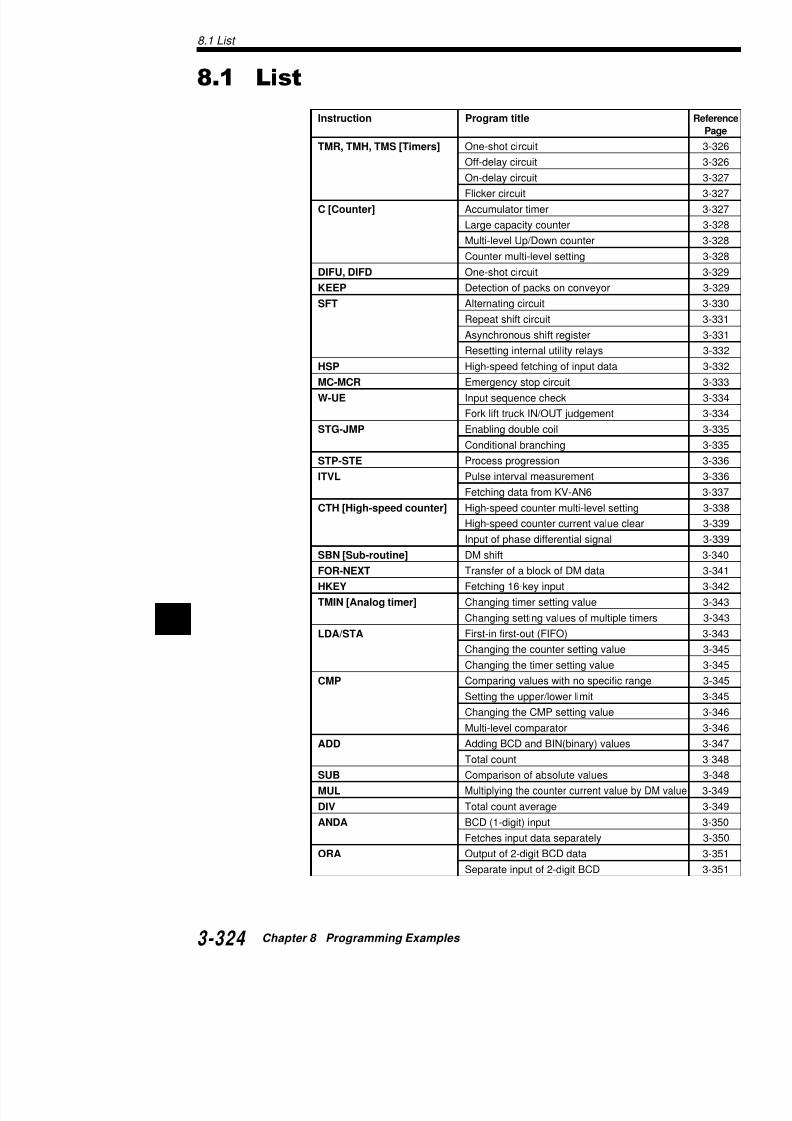
7/18/2019 Keyence Programming
http://slidepdf.com/reader/full/keyence-programming 348/392
8TMIN [Analog timer] Changing timer setting value
Changing setting values of multiple tim
LDA/STA First-in first-out (FIFO)
Changing the counter setting value
Changing the timer setting value
CMP Comparing values with no specific ran
Instruction Program title
EORA Judgement of matcing dataSRA/SLA Separate input of BCD
RRA/RLA Error input count
INC/DEC Total count
Up/Down count
MPX Display of 7-segment LED
DMX Output of error input No. in B
TBCD Output of 4-digit BCD data
Output of 8-digit BCD data
TBIN Output of 4-digit BCD data

7/18/2019 Keyence Programming
http://slidepdf.com/reader/full/keyence-programming 349/392
8.2 Details
8.2 Details
8.2.1 Reference Program Examples
Basic Instructions
Applications of TMR, TMH, and TMS Instructions Refer to p. 3-67 to p. 3-71.
One-shot circuit
When input relay 0000 turns ON, output relay 0500 turns ON and
specified time.
Timing diagram
Ladder diagram Coding
Off-delay circuit
When input relay 0000 turns ON, output relay 0500 turns ON. 05specified time after 0000 turns OFF.
Timing diagram
0500
0000
2s 2s
0000 #00020
T000
T000 005000500
2-s timer
0000
Line No. Instr
0000
0001
0002 T
0003 A
0004 O

7/18/2019 Keyence Programming
http://slidepdf.com/reader/full/keyence-programming 350/392
8
Ladder diagram Coding
0500
0000
2s
On-delay circuit
Output relay 0500 turns ON in a specified time after in
When input relay 0000 turns OFF, output relay 0500 a
Timing diagram
Ladder diagram Coding
Flicker circuit
Output relay 0500 turns ON and OFF repeatedly while
Timing diagram
Ladder diagram Coding
0500
0000
2s 1s
0000 #00020
T000
0500T000
2-s timer
0500
0000
2s
1s 1s
2s
0000 #00020
T000
T000
2-s timer
0500
#00010
T001
T001
1-s timer
Line N
0000
0001
0002
0003
Line N
0000
0001
0002
0003
0004

7/18/2019 Keyence Programming
http://slidepdf.com/reader/full/keyence-programming 351/392
Accumulator timer (Remains ON in case of pow
Counts special utility relay 2006 (1-s clock pulse) for 3count value to C002 Accumulates the count for 10000
0004
0005
8.2 Details
0004Low-order4 digits
High-order4 digits
STATBCDLDAC000 8500
STATBCDLDA
C001 8600
Large capacity counter
Accumulates 1 count to C001 for every 10000 counts by C000. T
count up to 655350000.Count input relay 0000Reset relay 0001
Ladder diagram Coding
Multi-level UP/DOWN counter
UP/DOWN counter which allows the count setting value up to 99• UP input relay: 0001
• DOWN input relay: 0002• Reset input relay: 0003
The example below outputs the high-order 4 digits of 8-digit BCDthe low-order 4 digits of 8-digit BCD to UDC000.
Ladder diagram Coding
#10000C000
C000
0001 C000
0001 #65535C001
1000
1000
0000
Line No. Instructi
0000 LDB
0001 ANB
0002 C
0003 LD
0004 OUT
0005 LDB
0006 C
Line No. Instructi
0000 LD
0001 LD
0002 LD
0003 UDC
0004 LD0005 AND
0001
#09999
UP
UDC000
0002
0003
C000 0001
DW
RES
#09999
UPUDC001
BCD:Low-order4 digits
BCD:High order

7/18/2019 Keyence Programming
http://slidepdf.com/reader/full/keyence-programming 352/392
8 0006 LD
0007 AND
0008 LD
0009 UDC
C000
0003
0002 #09999
DW
RES
High-order4 digits
Coding
Application of DIFU, DIFD Instructions
One-shot circuit using differentiate instruction
When input relay 0000 turns ON/OFF, output relay 05shot (1 second).
Timing diagram
Ladder diagram Coding
Line No. Instruction Operand Line N
0000 LDB 0001 00120001 C 000 #09999 0000 0013
0002 LD 2002 0014
0003 LDA C000 0015
0004 CON 0016
0005 MPS 0017
0006 CMP #00999 0018
0007 CON 0019
0008 ANB 2011 0020
0009 OUT 0500 00210010 MRD 0022
0011 CMP #01999
1000
0000
1S
1001
0500
0501 1S
1001 0501T002
0000 1000
DIFU
1001
DIFD
1000 0500
0500 #00010
T001
T001
Line No
0000
0001
0002
0003
0004
0005
0006
0007
0008
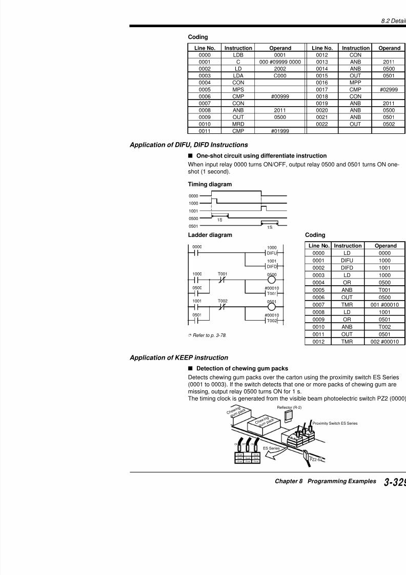
7/18/2019 Keyence Programming
http://slidepdf.com/reader/full/keyence-programming 353/392
Refer to p. 3-78.
0501 #00010
T002
0008
0009
0010
0011
0012
8.2 Details
Timing diagram
Ladder diagram
Executes SET when all input relays 0000 to 0003 are ON.Detects presence/absence of chewing gum packs at DOWN edgOutputs 1-s one-shot pulse from output relay 0500 when 1000 is
Coding
Refer to p. 3-80.
0000
1s
0001
0002
0003
0500
0000
1000
SET
KEEP
1001RES
0000 1001
DIFD
1001 0500
0500 #00010
T001
T001
0001 0002 0003
1000
Excecutes SET whenall input relays 0000 to0003 are ON.
Detects presence/absenceof chewing gum packs atDOWN edge of 0000.
Outputs 1-s one-shot pulsefrom output relay 0500when 1000 is OFF.
Line No. Instruction Operand Line No. Instruction
0000 LD 0000 0007 DIFD
0001 AND 0001 0008 LD
0002 AND 0002 0009 ANB
0003 AND 0003 0010 OR
0004 LD 1001 0011 ANB
0005 KEEP 1000 0012 OUT
0006 LD 0000 0013 TMR
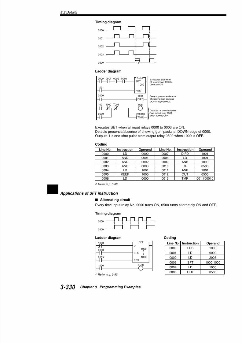
7/18/2019 Keyence Programming
http://slidepdf.com/reader/full/keyence-programming 354/392
8Applications of SFT instruction
Alternating circuit
Every time input relay No. 0000 turns ON, 0500 turns alternately
Repeat shift circuit
Turns ON every output for a second sequentially. Sets
scan only at startup) and shifts outputs from 7500 to 7When 1005 turns ON, 1000 is set and the same seque
Ladder diagram Coding
Synchronous shift register
Turns ON input relay 0002 to reset the shift register (1input to 0000 does not synchronize with the clock inpu
Timing diagram
2008
T001
2003
T001
2003
1000
DSFT
1000
1001
1002
CLK
RES
7502
1005
1003 7503
#00010
T001
7500
7501
1004 7504
1005 1000
SET
1000
SET
0000
0001
1000
Line N
0000
0001
0002
00030004
0005
0006
0007
0008
0009
0010
0011
0012
0013
0014
0015
0016
0017
0018
0019

7/18/2019 Keyence Programming
http://slidepdf.com/reader/full/keyence-programming 355/392
Ladder diagram Coding
1001
1002 ...
1100
8.2 Details
Resetting internal utility relays
When input relay No. 0000 turns ON, all internal utility relays No.
turn OFF.SFT instruction can be substituted for RES instruction. This applito reset many relays at one time.
Ladder diagram Coding
Applications of HSP instruction
High-speed fetching of input data
When the input signal at 0000 has pulses of 5-ms interval and inON, fetches data from input relay 0000 at high speed and outputpulse from output relay 0500.
Timing diagram
Ladder diagram Coding
* To input a signal having pulse interval shorter than the scan t
2003
2003
0000
1000D
SFT
CLK
RES
1915
0001
0000
0500 1s
0001
0000
0500
#00010
T000
1-s timer
0500 T000
Outputs1-s one-shotpulse fromoutput relay0500.
0000HSP
Line No. Inst
0000
0001
0002 0003
Line No. Inst
0000
0001 H
0002
0003
0004 T
0005 A
0006 O
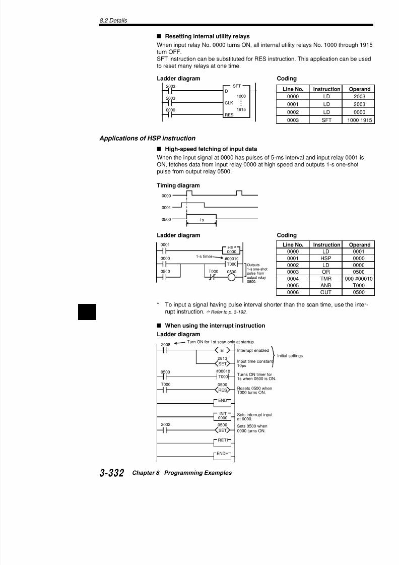
7/18/2019 Keyence Programming
http://slidepdf.com/reader/full/keyence-programming 356/392
8
2008Turn ON for 1st scan only at startup.
rupt instruction. Refer to p. 3-192.
When using the interrupt instruction
Ladder diagram
Coding
Refer to p. 3-86.
Application of MC-MCR instruction
Emergency stop circuit
When input relay 0000 is ON, 0500 turns ON for 1 s, tand then 0502 turns ON for 3 s, repeatedly.Once input relay 0000 turns OFF, 0500 turns ON whewhen 0002 is ON, and 0502 turns ON when 0003 is O
Timing diagram Coding
Ladder diagram
Line No. Instruction Operand Line No.
0000 LD 2008 00070001 EI 00080002 SET 2813 00090003 LD 0500 00100004 T000 #00010 00110005 LD T000 00120006 RES 0500
0000
0001
0002
0500
0501
0502
0003
0001
0002
0003
0004
0005
0006
0000
0000
1000
SET RES RES1100 1101 1102
DIFU
1002 1002
STG
1100 1200 #00010 T000JMP
1101
T000
MC
STG
1101 1201 #00020 T001JMP
1102
T001
STG1102 1202 #00030 T002
JMP1100
T002
MCR
1000 1001
Line N000000000000000000000000000000001001
001001001001001001001001002002002002
002002002002

7/18/2019 Keyence Programming
http://slidepdf.com/reader/full/keyence-programming 357/392
0007
0008
0009
0010
MC1001
0001
0002
1203
1204
002002002003003003003003
8.2 Details
8
0000
0001
0500
0501
0000
00010002
0003
0500
0000
1000 0002
1001 0003
0001
1002 0500
1000
1001
1002
Application Instructions
Application of W-UE instruction
Input sequence check
Output relay 0500 turns ON when input relay 0000 is ON and inp0003 turn ON in this sequence.Output relay 0500 turns OFF when input relay 0000 is OFF.
Timing diagram
Ladder diagram Coding
Fork lift truck IN/OUT judgementChecks the input sequence. Output relay 0500 turns ON when inON and then 0001 turns ON. Output relay 0501 turns ON when iturns ON and then 0000 turns ON.
Timing diagram
Line No. Instruct
0000 LD
0001 W-UE0002 LD
0003 W-UE
0004 LD
0005 W-UE
0006 LD
0007 OUT

7/18/2019 Keyence Programming
http://slidepdf.com/reader/full/keyence-programming 358/392
80501
Ladder diagram Coding
0000 0001 1000 0500
Leave
Line No. Instruct
0000 LD
Application of STG-JMP instruction
Enabling double coil
When start SW 0000 is pressed, output relay 0500 turrelays 0500 and 0501 turn ON for 2 s, and then outputurn ON for 3 s. The above sequence repeats.
Ladder diagram
Coding
The double coil operates normally through differedifferent STG instructions turn ON simultaneouslyi i h h i i
0000
1001
JMP
SET
10001100
DIFU1100
1000
STGT000#00010
T000
1002
JMP
1001
STGT001#00020
T001
1000
JMP
1002
STGT002#00030
T002
0500
0501
050205010500
0500
Turns ON 100
Output relay 0
Output relays
Output relays
Line No. Instruction Operand Line No. In
0000 LD 0000 0016
0001 DIFU 1100 0017
0002 CON 0018
0003 AND 1100 0019
0004 SET 1000 0020
0005 STG 1000 0021
0006 OUT 0500 0022
0007 CON 0023
0008 TMR 000 #00010 0024
0009 CON 0025
0010 AND T000 0026
0011 JMP 1001 0027
0012 STG 1001 0028
0013 OUT 0500 0029
0014 CON 0030
0015 OUT 0501 0031
CAUTION

7/18/2019 Keyence Programming
http://slidepdf.com/reader/full/keyence-programming 359/392
instruction has the priority.
Conditional branching
When input relay 0000 (start SW) turns ON, output reprogrammed for conditional branching, output 0501 tu
8.2 Details
8
Application of STP-STE instruction
Process progression
When input relay 0000 turns ON, output relay 0500 automaticallyand then 0501 turns ON for 3 s.
Ladder diagram Coding
Coding
Line No. Instruction Operand Line No. Instruction
0000 LD 0000 0014 OUT0001 DIFU 1100 0015 CON
0002 CON 0016 TMR
0003 AND 1100 0017 CON
0004 SET 1000 0018 AND
0005 STG 1000 0019 JMP
0006 OUT 0500 0020 STG
0007 MPS 0021 OUT
0008 AND 0001 0022 CON
0009 JMP 1001 0023 TMR0010 MPP 0024 CON
0011 AND 0002 0025 AND
0012 JMP 1002 0026 JMP
0013 STG 1001
0001
0002
0003
0004
0005
0006
0007
0008
0009
0010
0011
0000
SET1001
DIFU
1000 1000
STE
T001 0501
SET1002T000
1001
STE
STP
T000
1001T000
#00020
0500
RES1001T000
STP1002
RES1002T001
1002T001
#00030
Line No. Instruct
0000 LD
0001 DIFU
0002 CON
0003 AND0004 SET
0005 STP
0006 LD
0007 RES
0008 LDB
0009 OUT
0010 LD
0011 TMR
0012 LD
0013 SET
0014 STE

7/18/2019 Keyence Programming
http://slidepdf.com/reader/full/keyence-programming 360/392
80012
0013
0014
STE
END
ENDH
0014 STE
0015 STP
0016 LD
0017 RES
0018 LDB
ONOFF 500ms
Measure the pulse interval
Reset input relay 0002Output relay 0500 turns ONwhen the pulse interval is not within the range from 4
Ladder diagram
Coding
2008
0000
0001
0002
DM0000PLS
ITVL
PAUSE
RES
1000
1000 0500
STA
DM0000
SET
LDA
#00001
2008STA
DM0001
LDA
#00051
2008STA
DM0002
LDA
#00049
2008STA
DM0003
LDA
#00010
1002RES
0500
STA
DM0100
1001
LDA
DM0007
Sets mode 1 i
Sets MAX. se
Sets MIN. sett
Sets the averaDM0003.
Measures theturns ON.
Pauses measON.
Resets measuON.
Writes the aveDM0100 and measurement
Turns On outpinterval is not mm.
Line No. Instruction Operand Line No. I
0000 LD 2008 0015
0001 LDA #00001 0016
0002 CON 0017

7/18/2019 Keyence Programming
http://slidepdf.com/reader/full/keyence-programming 361/392
0002 CON 0017
0003 STA DM0000 0018
0004 LD 2008 0019
0005 LDA #00051 0020
0006 CON 0021
8.2 Details
8
2008
2003
0001
0002
DM0000PLS
ITVL
PAUSE
RES
1000
STA
DM0000
LDA
#09000
2008STA
DM0001
LDA
#02000
2008STA
DM0002
LDA
#00900
2008STA
DM0003
LDA
#00010
1003STA
DM0100
LDA
DM0007
2008
STA
DM0002
LDA
#03000
0001
STA
DM0001
LDA
#02000
STA
DM0000
LDA
#01000
SET
2813
CTH100005
Ladder diagram Coding
Refer to p. 3-117.
Applications of High-speed counter
High-speed counter multi-level setting
Sets the high speed counter comparator value of the input relay 0• #0100 DM0000
• #0200 DM0001• #0300 DM0002
When a comparator value is greater than the setting value:• DM0000 0500 turns ON.• DM0001 0501 turns ON.• DM0002 0502 turns ON.
Ladder diagram Coding
Line No. Instructi
0000 LD0001 LDA
0002 CON
0003 STA
0004 LD
0005 LDA
0006 CON
0007 STA
0008 LD
0009 LDA
0010 CON0011 STA
0012 LD
0013 LDA
0014 CON
0015 STA
0016 LD
0017 LD
0018 LD
0019 ITVL
0020 LD0021 LDA
0022 CON
0023 STA
Line No. Instructi
0000 LD0001 SET0002 CON0003 LDA
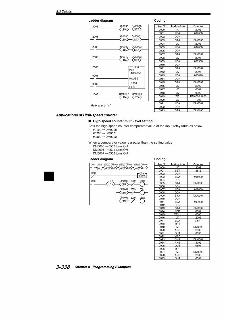
7/18/2019 Keyence Programming
http://slidepdf.com/reader/full/keyence-programming 362/392
82002
CMP
DM0000
LDA
CTH1 2009 0500
CMP
DM0001 2009 0501
0003 LDA0004 CON0005 STA0006 CON0007 LDA0008 CON0009 STA
2008
2002 CTH10005
RES
CTH1
SET
2203
SET
2813
#60000
CTC2
CTC2
RES
0502
RES
CTC2T0010502 #00030
T001
High-speed counter current value clear
Counts pulses at input relay 0005. When the count va60000, clears the current value of high speed counter relay 0502 for 3 s.
Ladder diagram Coding
Input of phase differential signal
Inputs phase differential signals to input relays 0004 aCTH0.
Writes the count value into DM0000.When high speed counter CTH0 reaches 60000, cleasets output relay 0500, and stops fetching count valueSets 0008 as external reset.
Ladder diagram
Line No
0000
0001
0002
0003
00040005
0006
0007
0008
0009
0010
0011
0012
00130015
0016
0017
0018
2008
RES
CTH0
SET
2115
0500
RES
2114
SET
2113
SET
2103
SET
2813
EI
CTH0
00004#60000CTC02002 DM0000CTH0
Initial settings

7/18/2019 Keyence Programming
http://slidepdf.com/reader/full/keyence-programming 363/392
STALDA
END
INTCTC0
8.2 Details
8
0000
STA
TM03
LDA
#00030
STA
TM02
LDA
#00010
END
00CALL
SBN00
2002
STA
TM05
SUB
TM02
STA
TM04
ADD
#00001
LDA
TM03
FORTM05
1000DIFU
1000 Shifts data fromDM0010 to DM0030.
Designates theshift startDM No. (DM0010).
Designates theshift endDM No. (DM0030).
Shift level
Synchoronoussignal
External reset 0008 is predetermined on hardware even if yothe program. However, you have to set external reset enable
Coding
Line No. Instruction Operand Line No. Instruction
0000 LD 2008 0014 LDB
0001 EI 0015 CTH
0002 CON 0016 CTC
0003 SET 2813 0017 LD
0004 CON 0018 LDA
0005 SET 2103 0019 CON
0006 CON 0020 STA0007 SET 2113 0021 END
0008 CON 0022 INT
0009 RES 2114 0023 LD
0010 CON 0024 SET
0011 SET 2115 0025 RETI
0012 CON 0026 ENDH
0013 RES CTH0
Application of Subroutine CALL
DM shift
Shifts the data from current DM to the next DM at UP edge of thesignal (timing).As the number of DMs to be shifted increases, the required scanlonger.
Ladder diagram
CAUTION

7/18/2019 Keyence Programming
http://slidepdf.com/reader/full/keyence-programming 364/392
8
NEXT
2002
STA
#TM04
LDA
#TM03
DEC
TM04
DEC
TM03
Uses the indirect addressingfunction to designate DM Nos.
The program lines whichexecute the data shiftare groped as the subroutine.
Coding
Refer to p. 3-122.
Application of FOR-NEXT
Transfer of a block of DM data
Uses the indirect addressing function to transfer a blo
DM0099 to DM0100 - DM0199.
Ladder diagram Coding
Line No. Instruction Operand Line No. In
0000 LD 0000 0021
0001 DIFU 1000 0022
0002 CON 0023
0003 AND 1000 0024
0004 LDA #00010 0025
0005 CON 0026
0006 STA TM02 0027
0007 CON 0028
0008 LDA #00030 0029
0009 CON 0030
0010 STA TM03 0031
0011 CON 0032
0012 CALL 00 0033
0013 END 0034
0014 SBN 00 0035
0015 LD 2002 0036
0016 LDA TM03 0037
0017 CON 0038
0018 ADD #00001 00390019 CON 0040
0020 STA TM04
FOR
SBN01
2002
STA
TMO3
LDA
#00100
STA
TMO2
LDA
#0000
2002
INC
TM03
INC
TM02
STA
#TM03
LDA
#TM02
#00100
1st DM No. oftransfer source
1st DM No. oftransfer destination
Number of DMs to be Transferred.
Line No
0000
0010
0001
0011
00020012
0003
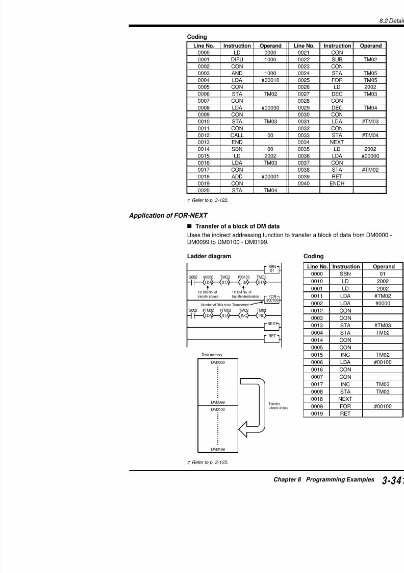
7/18/2019 Keyence Programming
http://slidepdf.com/reader/full/keyence-programming 365/392
NEXT
RET
0013
0004
0014
0005
8.2 Details
8
2008
SET
2814
2815
END
ENDH
HKEY0000
STA
DM0000
ORA
TM06
SLA
#04
LDA
DM0000
DW
#00000
2815
DMXSTA
TM05
CMP
TM05
ANDA
$03FF2010
0500
LDA
2900
KEY IN
Input value(BCD)
2010
STA
TM06
2002
2815
STA
TM05
CMP
TM05
ANDA
$03FF2010
LDA
2900 2010
2915
DM0000
Input value(BCD)
24 VDC COM 000 001 002 003
COM 500 501 502 503KV
0 1 2 3
4 5 6 78 9 A B
C D E F
Application of HKEY instruction
Fetching 16-key input
Writes the following 16-key input value into DM0000 in 4-digit BCPressing the keys in the lower line clear the input numerical valuWires the 16-key input terminals using 4 outputs and 4 inputs as
Ladder diagram
Coding
Line No. Instruction Operand Line No. Instruction
0000 LD 2008 0021 AND

7/18/2019 Keyence Programming
http://slidepdf.com/reader/full/keyence-programming 366/392
0001 SET 2814 0022 ANDA
0002 LD 2002 0023 CON
0003 HKEY 0000 0500 0024 CMP
0004 LD 2815 0025 CON
2002
0000
0500
#00010
T000
0500 T000
STA
T000
TMIN
0
2002
0000
0500
#00010
T000
0500 T000
STA
T002
STA
T001
STA
T000
TMIN
0
0001
0501
#00010
T001
0501 T001
0002
0502
#00010
T002
0502 T002
Arithmetic Instructions
Applications of TMIN (Analog timer) instruction
Changing timer setting value
Uses analog timer (TMIN0) to change the timer setting
Ladder diagram Coding
Changing setting values of multiple timers
Uses analog timer (TMIN0) to change setting values o
Ladder diagram Coding
Line No
0000
0001
0002
0003
0004
0005
0006
0007
0008
Line No
0000
0001
0002
0003
00040005
0006
0007
0008
0010
0011
0012
00130014
0015
0016
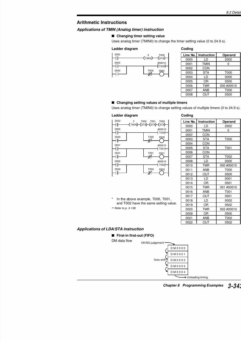
7/18/2019 Keyence Programming
http://slidepdf.com/reader/full/keyence-programming 367/392
* In the above example, T000, T001,and T002 have the same setting value.
Refer to p 3 138
0016
0017
0018
0019
0020
8.2 Details
8
Line No. Instruction Operand Line No. Instruction
0000 LD 0000 0035 STA0001 DIFU 1000 0036 CON0002 CON 0037 LDA0003 AND 1000 0038 CON0004 MPS 0039 STA0005 AND 0001 0040 LD0006 LDA $1111 0041 LDA0007 CON 0042 CON0008 STA DM0000 0043 CMP
0009 MPP 0044 CON0010 ANB 0001 0045 AND0011 LDA $5555 0046 LDA0012 CON 0047 CON
The data once fetched is written into DM0004, DM0003, ..., DM0the unloading timing, unload the data from DM0004 and shifts thenext DM.
The ON/NG judgement and unloading timings can be used in asygrams.
Ladder diagram
Coding
2002
LDA
$0000
STA
DM0004
LDA
DM0003
CMP
$0000 2010
LDA
DM0004
STA
DM0003
0000
LDA
$11111000 0001
STA
DM00001000DIFU
Transfers $1111 to DM0000.
LDA$55550001
STADM0000
Transfers $5555 to DM0000.
OK/NG judgementOK/NG judgement timing
2002
LDA
$0000
STA
DM0003
LDA
DM0002
CMP
$0000 2010
LDA
DM0003
STA
DM0002
2002
LDA
$0000
STA
DM0002
LDA
DM0001
CMP
$0000 2010
LDA
DM0002
STA
DM0001
2002
LDA
$0000
STA
DM0001
LDA
DM0000
CMP
$0000 2010
LDA
DM0001
STA
DM0000
0002
LDA
$0000
STA
DM0004
Unloading timing Transfers $0000 to DM at unloading timing.
Compares the DM valIf it is equal to $0000, value of the previous Dthen writes $0000 into
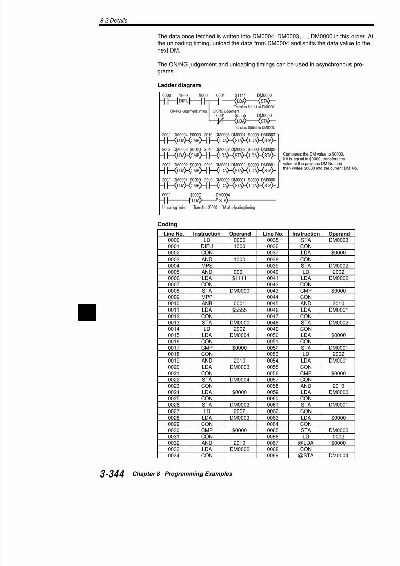
7/18/2019 Keyence Programming
http://slidepdf.com/reader/full/keyence-programming 368/392
0013 STA DM0000 0048 STA0014 LD 2002 0049 CON0015 LDA DM0004 0050 LDA0016 CON 0051 CON
2002
0005 #9999
C000
STAC000
LDADM0000
0001
Changing the counter setting value
Sets the setting value of counter C000 to DM0000. Re
Ladder diagram Coding
Changing the timer setting value
Sets the setting value of timer T000 to DM0000. Rese
Ladder diagram Coding
Refer to p. 3-140.
Application of CMP (compare) instruction
When comparing values with no specific range
Turns ON 0500 when the DM0000 value is smaller thaTurns ON 0501 when the DM0000 value is equal to thTurns ON 0502 when the DM0000 value is greater tha
Ladder diagram Coding
Line No
0000
0001
0002
0003
0004
0005
2002
0005 #9999
T000
STA
T000
LDA
DM0000 Line No
0000
0001
00020003
0004
0005
2002
05022011
CMP
#01000
LDA
DM000 05002009
DM0000 <#01000
DM0000
=#01000
DM0000 >#01000
05012010
Line No
0000
0001
00020003
0004
0005

7/18/2019 Keyence Programming
http://slidepdf.com/reader/full/keyence-programming 369/392
0005
0006
0007
0008
8.2 Details
8
2002
05012009
CMP
DM0000
LDA
C000 05002009
2002DIV
#00010MUL
#00004ADD
#00001TMIN
0
0001 #09999
C000
00000
STADM0000 Sets the TMIN setting
range from 0 to 100.
Coding
Line No. Instruction Operand Line No. Instru
0000 LDB 0001 0008 OU0001 C 001 #09999 0000 0009 LD
0002 LD 2002 0010 LD
0003 LDA C001 0011 CO
0004 CON 0012 CM
0005 CMP #01000 0013 CO
0006 CON 0014 AN
0007 ANB 2011 0015 OU
Changing the CMP setting valueCompares the current value of C000 to the CMP setting value. Svalue to analog timer TMIN0.The following example changes the setting value within the rangeTurns ON 0500 when the C000 value is smaller than the CMP seTurns ON 0501 when the C000 value is greater than the CMP se
Ladder diagram
Coding
Line No. Instruction Operand Line No. Instruction
0000 LD 2002 0011 C
0001 TMIN 0 0012 LD
0002 CON 0013 LDA
0003 ADD #00001 0014 CON
0004 CON 0015 CMP
0005 MUL #00004 0016 MPS
0006 CON 0017 AND
0007 DIV #00010 0018 OUT
0008 CON 0019 MPP

7/18/2019 Keyence Programming
http://slidepdf.com/reader/full/keyence-programming 370/392
0008 CON 0019 MPP
0009 STA DM0000 0020 ANB
0010 LDB 0001 0021 OUT
0001 #09999
C000
2002 0500#00999C000 ≤ 00999LDA
C000
CMP
0501
0502
2011
#01999
CMP
2011 0500
#02999
CMP
2011 0500 0501
0000
00999 < C000 ≤
01999 < C000 ≤
Ladder diagram
Coding
Refer to p. 3-146.
Application of ADD instruction
Adding BCD and BIN values
Adds a 4-digit BCD input value (7000 to 7015) to the cwrites the sum into DM0100.
Ladder diagram
2002
ADD
DM0000
LDA
C001
2002
TBINLDA
7000
STA
DM0100
STA
DM0000
Converts BCD in
Adds converted
Line No. Instruction Operand Line N
0000 LDB 0001 0012
0001 C 000 #09999 0000 0013
0002 LD 2002 0014
0003 LDA C000 0015
0004 CON 00160005 MPS 0017
0006 CMP #00999 0018
0007 CON 0019
0008 ANB 2011 0020
0009 OUT 0500 0021
0010 MRD 0022
0011 CMP #01999

7/18/2019 Keyence Programming
http://slidepdf.com/reader/full/keyence-programming 371/392
0001 #09999
C001
ADDLDA
0000
STA Adds converted C001 and writes
8.2 Details
8
0000
LDA
C001
STA
DM0001#09999C001
0001
0000
LDA
C002
STA
DM0002#09999C002
0002
0000
LDA
C003
STA
DM0003#09999
C003
00032002
ADD
DM0002
LDA
DM0001
STA
DM0100
ADD
DM0003
2002
CMP
#00052009
LDA
DM0000
SUB
DM0001 10002009
Total count
Writes total count of counters C001 to C003 into DM0100. The towithin 65535.
Ladder diagram
Coding
Line No. Instruction Operand Line No. Instructi
0000 LDB 0000 0013 C
0001 C 001 #09999 0001 0014 CON
0002 CON 0015 LDA0003 LDA C001 0016 CON
0004 CON 0017 STA
0005 STA DM0001 0018 LD
0006 LDB 0000 0019 LDA
0007 C 002 #09999 0002 0020 CON
0008 CON 0021 ADD
0009 LDA C002 0022 CON
0010 CON 0023 ADD
0011 STA DM0002 0024 CON0012 LDB 0000 0025 STA
Writes C001 current value into DM0
Writes C002 current value into DM0
Writes C003 current value into DM0
Writes total count (DM0001 + CM0DM100.
Refer to p. 3-150.
Application of SUB instruction
Comparison of absolute values
Compares the DM0000 value to the DM0001 value and turns ONdifference of the two absolute values is greater than 5.
Ladder diagram
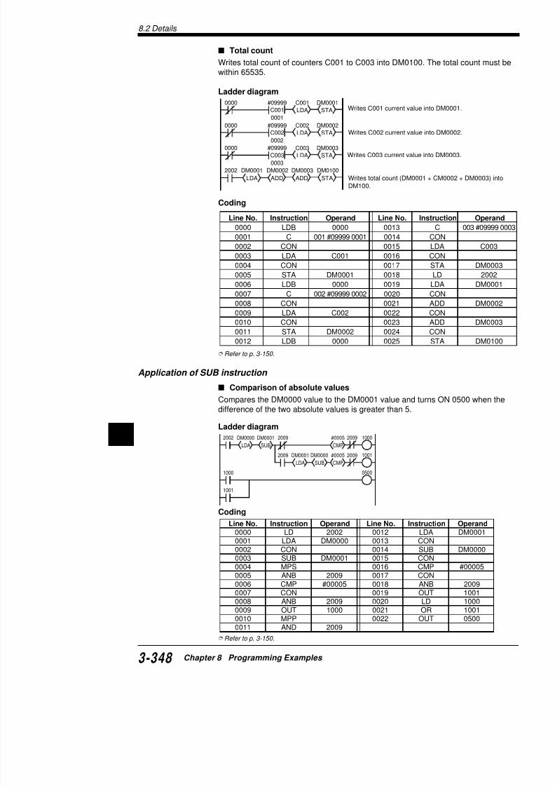
7/18/2019 Keyence Programming
http://slidepdf.com/reader/full/keyence-programming 372/392
CMP
#0005
SUB
DM0000
LDA
DM00012009 10012009
1000 0500
2002
LDA
TM00
STA
DM0100
MUL
DM0000
LDA
C001
0001 #09999
C001
0000
STA
DM0101
#09999
00001
C0010000
STA
DM0001
LDA
C001
DM0001 DM0002 DM0003
2002
#09999C002
0000STA
DM0002
LDA
C002
#09999
C003
0000
STA
DM0003
LDA
C003
ADDLDA
DM0001
ADD
DM0003
00002
00003
DM0002
Writes the C001 currentvalue into DM0001.
Writes the C002 currentvalue into DM0002.
Writes the C003 currentvalue into DM0003.
Application of MUL instruction
Multiplying the counter current value by DM va
Multiplies the counter current value by the DM0000 va16 bits of the product into DM0101 and low-order 16 bDM0100.
Ladder diagram Coding
Refer to p. 3-150.
Application of DIV instruction
Total count average
Outputs the average of 3 counter values in 4-digit BCD(C001 + C002 + C003) ÷ 3 BCD output value
The BCD value is output to 7500 to 7515.
Ladder diagram
Line No
0000
0001
00020003
0005
0004
0006
0007
0008
0009
0010
0011

7/18/2019 Keyence Programming
http://slidepdf.com/reader/full/keyence-programming 373/392
2002÷3 → Output to 07500to 07515 in 4-digit BCD.TBCDDIV
#00003
STA
07500
C di
8.2 Details
8Line No. Instruction Operand Line No. Instruction
Application of ANDA instruction
BCD (1-digit) input
Sets a 1-digit BCD value, which is input to 0000 to 0003, in C000
Ladder diagram
Coding
Fetches input data separately
Sets the low-order 2 digits of the BCD digital switch (7000 to 700and the high-order 2 digits to timer T001.
Ladder diagram
Coding
Line No. Instruction Operand Line No. Instruction
0000 LD 2002 0005 TBIN
0001 LDA 0000 0006 CON
0002 CON 0007 STA
0003 ANDA $000F 0008 LDB
0004 LD 2002 0009 C
2002ANDA$000F
LDA0000
2002STAC000
TBIN
#09999
C000
7000
7001
Fetches data of 0000 to 0015 and retains dato 0003 only.
Converts data to BIN and writes it into C000.
Sets C000.
2002
2002
LDA
#09999C000
0001
0000
7000
ANDA
$FF00
TBIN
#08
SRA STA
T001
LDA
7000
ANDA
$00FF
STA
C000
TBIN
#09999T001
0001
Converts data of 7000 to 70writes it into C000.
Shifts data to right by 8 bitsBIN, and writes it into T001.
Sets C000.
Sets T001.

7/18/2019 Keyence Programming
http://slidepdf.com/reader/full/keyence-programming 374/392
0000 LD 2002 0011 ANDA
0001 LDA 7000 0012 CON
0002 CON 0013 SRA
Application of ORA instruction
Output of BCD 2-digit data
Converts the current value of counter C000 to BCD anto output relays 7500 to 7507.However, retain ON/OFF of 7508 to 7515 which are lo
Ladder diagram
Coding
Separate input of 2-digit BCD
Fetches only 2 digits of the BCD digital switch (7000 t8003 for the 2nd digit) and sets it as the counter value
Ladder diagram
#00099
0001
C0000000
2002
2002STA
DM0000
ANDA
$FF00
2002ANDA
$00FF
TBCD
STAORA
DM0000 7500
LDA
7500
LDA
C000
Sets C000.
Writes data of 7008 to
ORs the data in the intDM0000 data and sento 7515.
Converts the current varetains the low-order 2internal register.
Line No. Instruction Operand Line N
0000 LDB 0000 0009
0001 C 000 #00099 0001 0010
0002 LD 2002 0011
0003 LDA 7500 0012
0004 CON 0013
0005 ANDA $FF00 0014
0006 CON 0015
0007 STA DM0000 00160008 LD 2002 0017
#00099
0001
C001
0000
2002
STA
DM0000
ANDA
$000F
LDA
7000
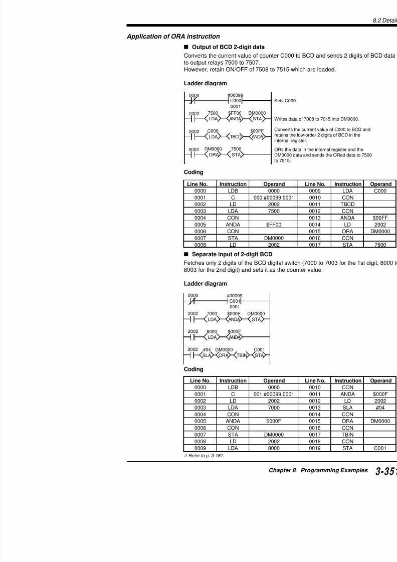
7/18/2019 Keyence Programming
http://slidepdf.com/reader/full/keyence-programming 375/392
2002
ANDA
$000F
LDA
8000
8.2 Details
8
1 0 1 1 1 0 1 1 1 0 1 1 1 0 1 1D15D14D13D12D11D10 D9 D8 D7 D6 D5 D4 D3 D2 D1 D0
0 0 0 0 0 0 0 0 1 1 1 1 1 1 1 1
0 0 0 0 0 0 0 0 1 0 1 1 1 0 1 1
0 0 0 0 0 0 0 0 1 0 1 0 1 0 1 0
0 0 0 0 0 0 0 0 0 0 0 1 0 0 0 1
ANDA
EORA
$BBBB
$00FF
$00BB
$00AA
$0011
7000 to 7015
Operand
Internal register
DM0000
Internal register → 2010 is OFF. Whevalue of internal reis 0000, 2010 turn
Judges match between the operand and the data
2008
2002
LDA
7000
ANDA
$00FF DM0000
EORA
LDA
$00AA
STA
DM0000
2010 0500
Application of EORA instruction
Judgement of matching data
Turns ON 0500 (“OK” output) when the ON/OFF statuses of inpu7007 match the DM0000 setting value.
Ladder diagram Coding
For easy comprehension, the following data is set temporarily.
When 2010 is ON, the two values match.When 2010 is OFF, the two values do not match.
Refer to p. 3-164.
Application of SRA/SLA instructions
Separate input of BCD
Fetches only 2 digits of the BCD digital switch (7012 to 7015 for t8003 f th 2 d di it) d t it th t l
Line No. Instructio
0000 LD
0001 LDA
0002 CON
0003 STA
0004 LD0005 LDA
0006 CON
0007 ANDA
0008 CON
0009 EORA
0010 CON
0011 AND
0012 OUT

7/18/2019 Keyence Programming
http://slidepdf.com/reader/full/keyence-programming 376/392
8003 for the 2nd digit) and sets it as the counter value.
Ladder diagram
Coding
Refer to p. 3-166.
Application of RRA/RLA instructions
Error input count
Writes the number of error detection sensors, which a(7000 to 7015) and turn ON, into DM0000.
Ladder diagram
Coding
Line No. Instruction Operand Line N
0000 LD 0001 0011
0001 C 001 #00099 0000 0012
0002 LD 2002 0013
0003 LDA 7000 0014
0004 CON 0015
0005 ANDA $F000 0016
0006 LD 2002 0017
0007 SRA #12 0018
0008 CON 0019
0009 STA DM0000 00200010 LD 2002 0021
Line No. Instruction Operand Line No. In
0000 LD 2002 0009
0001 LDA 7000 00100002 FOR #00016 0011
0003 LD 02002 0012
0004 RRA #01 0013
0005 CON 0014
Writes the TM10 data into #00000 to TM10.
2002
RRA
#01
INC
TM10
LDA
7000
#00016
2002
LDA
TM10
LDA
DM0000
STA STA
TM102002
2009
#00000
NEXT
FO R
Writes the data of 7000 to7015 into internal register.
Executes FOR-NEXT instr
Shifts the data including caand increments TM10 by 1
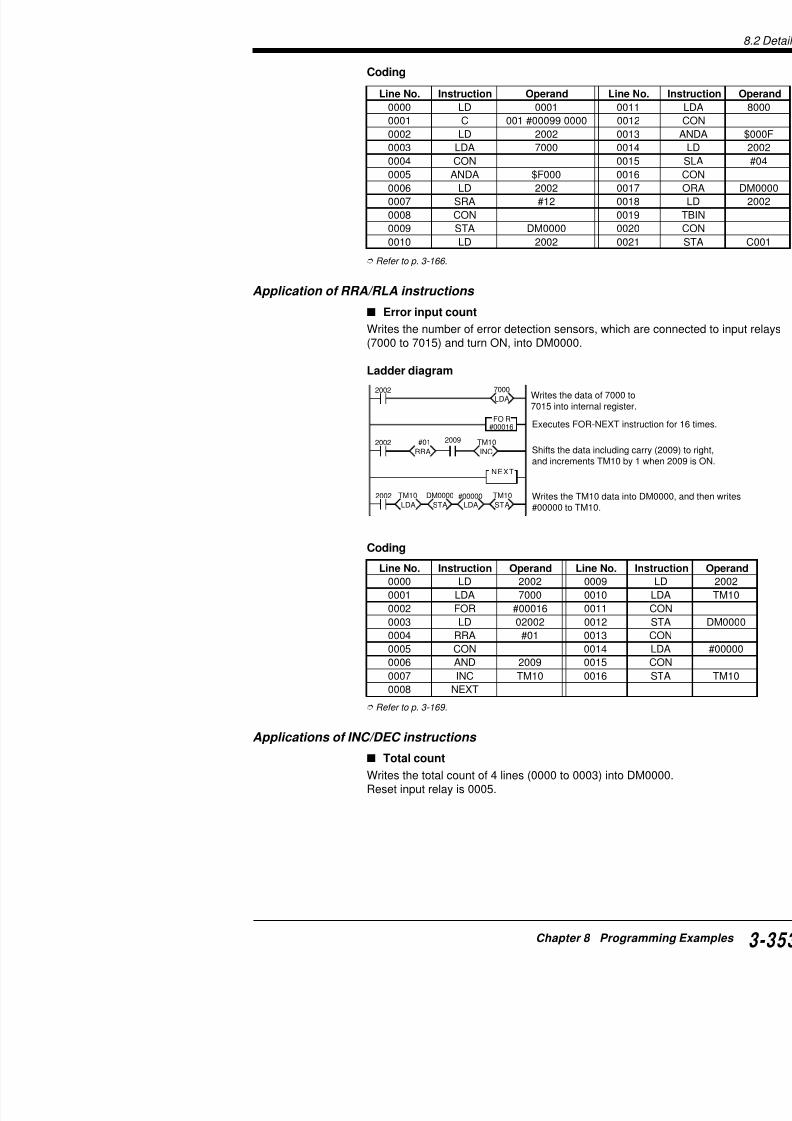
7/18/2019 Keyence Programming
http://slidepdf.com/reader/full/keyence-programming 377/392
0005 CON 0014
0006 AND 2009 0015
0007 INC TM10 0016
8.2 Details
8
2008STA
DM0000
LDA
#00000
0000INC
DM0000
0005DW
#00000
0001DEC
DM0000
Sets #00000 to DM0000 at startup.
Increments DM0000 by 1 at UP edgeof input relay 0000.
Decrements DM0000 by 1 at UP edgof input relay 0001.
Clears DM0000 to #00000 when 000
Ladder diagram
Coding
UP/DOWN count
Performs UP count when input relay 0000 turns ON.Performs DOWN count when input relay 0001 turns ON.
Writes the count value into DM0000.Reset input relay is 0005.
Ladder diagram
Line No. Instruction Operand Line No. Instruction
0000 LD 2008 0007 @INC
0001 LDA #00000 0008 LD
0002 CON 0009 @INC
0003 STA DM0000 0010 LD0004 LD 0000 0011 @INC
0005 @INC DM0000 0012 LD
0006 LD 0001 0013 DW
2008STA
DM0000LDA
#00000
0000INC
DM0000
0003INC
DM0000
0005DW
#00000
0001INC
DM0000
0002INC
DM0000
DM0000
Sets #00000 to DM0000 at startup.
Increments DM0000 by 1 at UPedge of input relay 0000.
Increments DM0000 by 1 at UPedge of input relay 0001.
Increments DM0000 by 1 at UPedge of input relay 0002.
Increments DM0000 by 1 at UPedge of input relay 0003.
Clears DM0000 to #00000 when0005 turns ON.

7/18/2019 Keyence Programming
http://slidepdf.com/reader/full/keyence-programming 378/392
DW
DM0000
Clears DM0000 to #00000 when 000turns ON.
a
f b
e c
g
d
a. 7500
b. 7501
c. 7502
d. 7503
e. 7504f. 7505
g. 7506
Application of MPX instruction
Display of 7-segment LED
Displays the current value of counter C000 to the 7-seOutputs from 7500 to 7571.Connection of 7 segmentsConnect each of 7 segments to output relays as show
Ladder diagram Coding
1000
1004
1005
1006
STA
7500
LDA
$003F
1001
STA
7500
LDA
$0006
1002
STA
7500
LDA
$005B
1003STA7500
LDA$004F
1007STA7500
LDA$0007
C000 #00009
C000 STA
1000
MPX
#0
LDA
C000
0000
Converts the counter value to 16-bitdata using the MPX instruction.Auto reset counter
STA
7500
LDA
$0066
STA
7500
LDA
$006D
STA
7500
LDA
$007D
Sends internal register data tooutput relays starting from 7500.
1008STA
7500
LDA
$007F
1009 7500$006F
0
1
2
3
4
5
6
7
8
Line No000000240001
0025000200260003002700040028000500290006003000070031000800320009003300100034
001100350012003600130037

7/18/2019 Keyence Programming
http://slidepdf.com/reader/full/keyence-programming 379/392
1009STA
7500
LDA
$006F9
003700140038
8.2 Details
8
2002
DMXLDA
07000
2002
ANDATBCD
$00FF
STA
8000
STA
7500
TBCDLDA
0001 #09999
C001
2002 C001
0000
Converts the most significant bit of (7000 to 7015) to 4-bit BIN data andinternal register.Converts internal register data to BCexecutes ANDA instruction, and outto 8000 to 8015.
Line No. Instruction Operand Line No. Instru0000 LDB 0001 0004 CO
0001 C 001 #09999 0000 0005 TBC
0002 LD 2002 0006 CO
0003 LDA C001 0007 ST
Application of DMX instruction
Output of error input No. in BCD
Outputs the error sensor No. from input relay 7000 to 7015 to ou8507 in 2-digit BCD.
Ladder diagram
Coding
Refer to p. 3-176.
Applications of TBCD instruction
Output of 4-digit BCD data
Outputs the current value of counter C001 to 7500 to 7515 in 4-d
Ladder diagram
Coding
Line No. Instruction Operand Line No. Instruction
0000 LD 2002 0005 TBCD
0001 LDA 7000 0006 CON
0002 CON 0007 ANDA
0003 DMX 0008 CON
0004 LD 2002 0009 STA

7/18/2019 Keyence Programming
http://slidepdf.com/reader/full/keyence-programming 380/392
0003 LDA C001 0007 ST
Output of 8-digit BCD data
MULLDA
2002
LDASTADIV TBCD STA
DM0000 DM0001 #10000 DM0101 TM01 7500
LDA TBCD STA
DM0101 8500
Line No. Instruction Operand Line No. In
0000 LD 2002 0010
0001 LDA DM0000 0011
0002 CON 0012
0003 MUL DM0001 0013
0004 CON 0014
0005 DIV #10000 0015
0006 CON 0016
0007 STA DM0101 0017
0008 CON 0018
0009 LDA TM01 0019
2002
TBINLDA
7000
STA
C001
#09999
0000
C001
0001
Converts data of 7000data and writes it into C
Sets C001.
Line No. Instruction Operand Line No. In
0000 LD 2002 0004
0001 LDA 7000 0005
Ladder diagram
Coding
Refer to p. 3-180.
Application of TBIN instruction
Output of 4-digit BCD data
Sets 4 digits of the BCD digital switch (7000 to 7015)
Ladder diagram
Coding
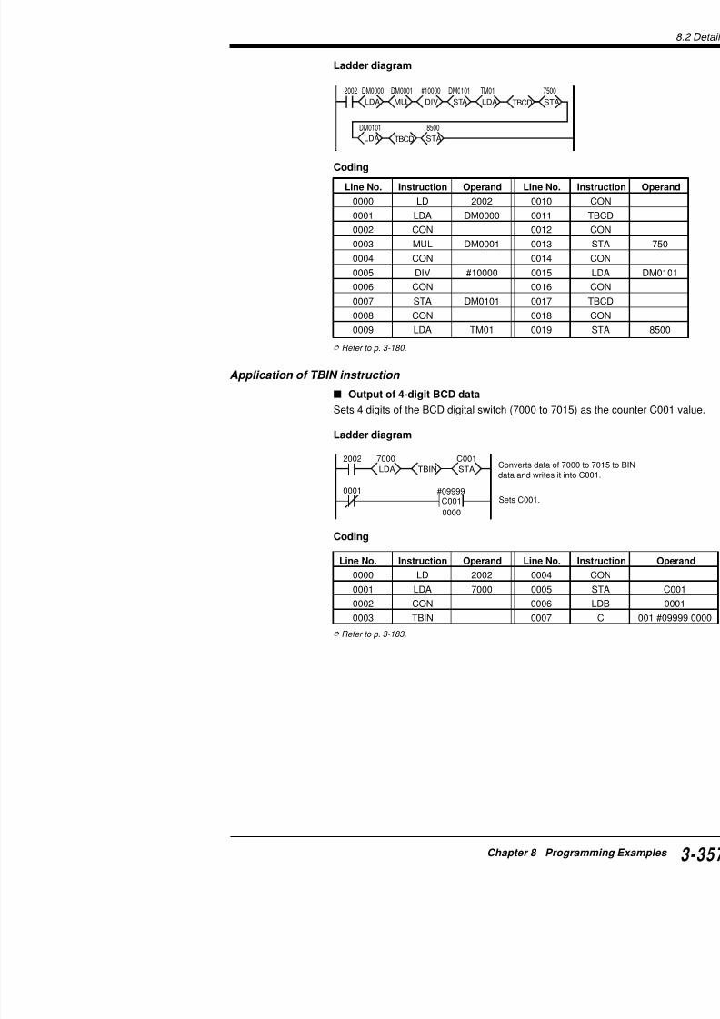
7/18/2019 Keyence Programming
http://slidepdf.com/reader/full/keyence-programming 381/392
0002 CON 0006
0003 TBIN 0007
8.2 Details
8

7/18/2019 Keyence Programming
http://slidepdf.com/reader/full/keyence-programming 382/392
Index

7/18/2019 Keyence Programming
http://slidepdf.com/reader/full/keyence-programming 383/392
n d e x
Index — For Visual KV User’s Only
The following is the index with some descriptions for yo
Index — For Visual KV User’s Only
esopruP eltiT
A
nieulavecivedgnignahc,wodniWsseccA edomeciveD
nisedomgnignahc,wodniWsseccA kgnitteser / gnittesdnasedomgnitceleS
nisnoitceridgniyalpsid,wodniWsseccA segassemresU
nisrorregniyalpsid,wodniWsseccA sutatsrorrednasegassemrorrE
niyalpsidrorre,wodniWsseccA tsiLrorrE
nideepsnoitcelesecivedgnisaercni,wodniWsseccA noitcnufobruT
fosnoitcnufsemantrap,wodniwsseccA sseccAehtfosnoitcnufdnasemantraP
dnaNURneewtebCLPVKehtgnihctiws,wodniWsseccAnisedom)pots(MARGORP
edoMmetsyS
niremmirtlatigidgnisu,wodniWsseccA edoMremmirTlatigiD
tuobagninrael,snoitcurtsninoitacilppA snoitcurtsninoitacilppA
tuobagninrael,snoitcurtsnicitemhtirA snoitcurtsnicitemhtirA
B
tuobagninrael,snoitcurtsnicisaB snoitcurtsnicisaB
C
rofmetignittes,noitcnufhctiwsmaC noitcnufhctiwsmacrofdesueciveD
saVKgnisu,hctiwsmaC noitcnufhctiwsmaC
gniriuqca,gnikramEC gnikramECehtgniriuqcanonoitcirtseR
retupmoclanosrepdnaVKneewtebnoissimsnartdnammoC esnopser/dnammocnoitacinummoC
gnirudsruccororrenehw,noissimsnartdnammoC tsiledocrorrE
fosnoitacificeps,tropnoitacinummoC noitacificepSsnoitacinummoC
CLPVKotmehtgnittimsnart,stnemmoctcatnoC noitcnufevastnemmoctcatnoC
gnitcetorp,stcatnoC noitcetorptcatnoC
htiwsecnereffid,seiresVKlanoitnevnoC irepVKlanoitnevnochtiwytilibitapmoC
noitpmusnoctnerruC snoitacificepslareneG
D
otdengissasnoitcnuf,yromemataD seiromemataD
foeniltuo,eslupkcolctceriD tuptuoeslupkcolctceridfoeniltuO oitarFFO/NO1:1htiwseslupgnittuptuo,eslupkcolctceriD
gnisu 1:1fooitarFFO/NO
eslupelbairavhtiwseslupgnittuptuo,eslupkcolctceriDhtdiw
htdiweslupelbairaV
ps-hgihehthtiwgnittestuptuoesluP
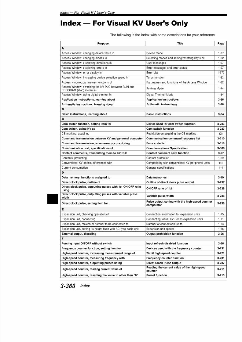
7/18/2019 Keyence Programming
http://slidepdf.com/reader/full/keyence-programming 384/392
I
rofmetignittes,eslupkcolctceriD ps-hgihehthtiwgnittestuptuoesluP
rotarapmoc
E
esopruP T
"0"oteulavehtgnitteser,retnuocdeeps-hgiH eeps-hgihehtgnitteseR
rofecruostupnignitceles,retnuocdeeps-hgiH dohtemtupnitnuoC
fosnoitacificeps,retnuocdeeps-hgiH s-hgihfosnoitacificepS
foeulavteserpehtgniyficeps,retnuocdeeps-hgiH hgihehtfoeulavteserP
rotarapmoc
retnuocgnirsa,gnisu,retnuocdeeps-hgiH noitcnufretnuocgniR
I
gnignahc,tinucisabfotnatsnocemittupnI ahctnatsnocemittupnI
gnittes,tinunoisnapxefotnatsnocemittupnI xeroftnatsnocemittupnI
fotnednepednisutatsyalergnittuptuo,noitcurtsnitpurretnI emitnacs tuptuO/tupnItceriD
tuobagninrael,snoitcurtsnitpurretnI noitcurtsnitpurretnI
nihtiwdesuebtonnactahtsnoitcurtsni,smargorptpurretnI tonnactahtsnoitcurtsnI
ybretnuocdeeps-hgihfoeulavtnerrucgnidaer,tpurretnI erutpactupnI
rofnoitidnoctupnignittes,tpurretnI retnirofgnittesytiraloP
detucexeerastpurretnilarevesnehw:tpurretnI ytiroirptpurretnI
K
gnisu,VKrofREDLIUBREDDAL / )SOD(eraWidercnIVK ehtgnisunehwsnoituaCerawtfostroppus
gnisusnoitcurtsnigniretne,)10(E3P-VK bahpla(tsil.oNnoitcnuF
htiwelbaliavasnoitcnuf,)10(E3P-VK tsil.soNnoitcnuF
gnitarepo,)10(E3P-VK arepognimmargorpcisaB
M
foyticapac,dracyromeM yticapacegarotS
foyrettabgnicalper,dracyromeM yrettabecalperoT
gnitucexe,MDfonoitareporotarapmocpets-itluM mrotarapmocpets-itluM
O
VKmorftuptuognilbasid,tuptuO oitcnufdelbasidtuptuO
P
VKfognitnuomlenaP otyltceridtinuagnihcattA
morfatadgniviecer,retupmoclanosreP atadtxetgnivieceR
otVKmorfatadgnittimsnart,retupmoclanosreP atadtxetgnittimsnarT
fonoitaluclac,yticapacmargorP uocetybehtgnitaluclaC
tuobagninrael,yticapacmargorP yticapacmargorP
dracyromemotnignivas,smargorP P-VKhtiwdesu[snoitcnuF
gnivird,rotomesluP ecorpgnittesretemaraP
Inde

7/18/2019 Keyence Programming
http://slidepdf.com/reader/full/keyence-programming 385/392
ycneuqerfderisedtatuptuoesluP lupycneuqerfdeificepS
tinucisabotdengissasoNyaleR tsilyaleR
I n
d e x
A
A/D converter ........................... 1-312 [AN6], 1-334 [AD4]A/D conversion table ................ 1-408 [AN6], 1-357 [AD4]ADD/@ADD: Add .................................................. 3-150AND: And ................................................................ 3-58ANB: And Bar ......................................................... 3-58ANDA/@ANDA: And A ......................................... 3-159ANL: And Load ....................................................... 3-61Application Instructions ...................... 3-36, 3-45, 3-95Arithmetic Instructions ...................... 3-38, 3-48, 3-134ASC/@ASC: ASCII Convert ................................ 3-183Assignment of Data Memory ................................. 3-19Assignment of I/O relay numbers ......................... 3-22
B
Basic Instructions ................................ 3-34, 3-42, 3-56Baud rate......................................... 2-136, 1-247 [KV-L2]
Break signal .......................................................... 3-308
C
C: Counter .............................................................. 3-72CALL: Subroutine Call ......................................... 3-122CMP/@CMP: Compare ......................................... 3-146COM/@COM: Complement .................................. 3-171Commands [Serial communication] ................... 3-310Communications ....................................... 2-135, 3-306
CON: Connect ....................................................... 3-102Connector wiring ....................................................... 1-72CTC: Counter Comparator .................................. 3-204CTH1: 16-Bit Counters ......................................... 3-204
D
Data Memory ........................................................... 3-19D/A converter ........................... 1-312 [AN6], 1-334 [AD4]
D/A conversion table ................ 1-408 [AN6], 1-357 [DA4]DEC/@DEC: Decrement Memory ........................ 3-172DI: Interrupt Disabled ........................................... 3-193DIFD: Differentiate Down ....................................... 3-78DIFU: Differentiate Up ........................................... 3-78Dimensions ............................................................. 1-404DIN rail (mounting) 1 180
Index — For KV-300, KV-10/80 User’
Index — For KV-300, KV-10/80 User’s Only
F
FOR: Repeat Start ......................
H
High-Speed Counters ................HKEY: 16 Key Input ....................HSP: High Speed ........................
I
INC/@INC: Increment Memory ..Indirect Addressing of Data MemInput Relays ................................Instruction List ...........................INT: Interrupt ..............................Interface [RS-232C] ....................Internal register ..........................
Internal Utility Relays .................Internal Clocks for CTH0 and CTInterrupt Instructions .................I/O distribution ...............................ITVL: Interval Timer ....................
J
JMP: Jump ..................................
K
KEEP: Keep ................................KV-10/16/24/40/80 ........................KV-300 ..........................................KV-AD4 .........................................KV-AN6 .........................................KV-B16R/B16S/C32T....................KV-C16X/C32X .............................
KV-DA4 .........................................KV-L2 ............................................KV-R1A/R16X/R16R/R16T/R8X/R8KV-U4/U5 ......................................KV mode [KV-L2] ..........................
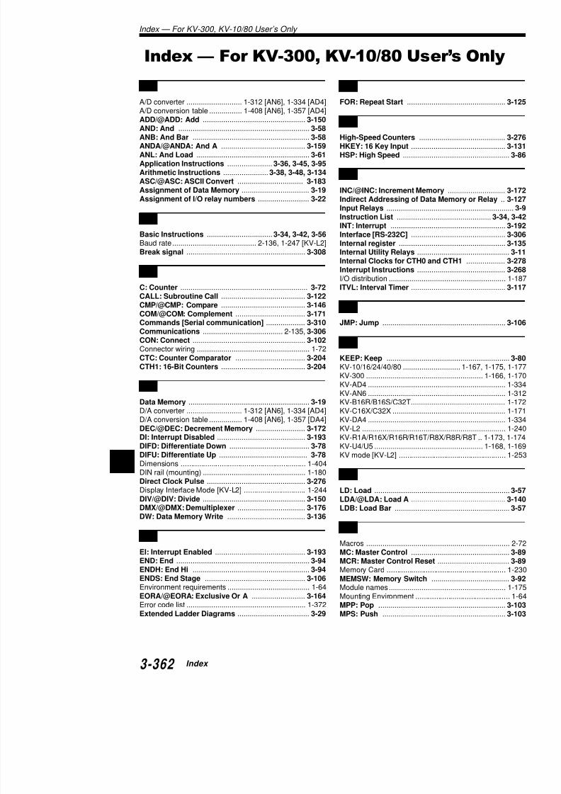
7/18/2019 Keyence Programming
http://slidepdf.com/reader/full/keyence-programming 386/392
DIN rail (mounting) .................................................. 1-180Direct Clock Pulse ................................................ 3-276
L
MPX/@MPX: Multiplexer ...................................... 3-176MRD: Read ............................................................ 3-103MUL/@MUL: Multiply ........................................... 3-150
N
NEXT: Repeat End ................................................ 3-125Non-procedure mode [KV-L2] ................................. 1-292NOP: No Operation ................................................ 3-94
O
OR: Or ..................................................................... 3-60ORA/@ORA: Or A ................................................. 3-161ORB: Or Bar ............................................................ 3-60ORL: Or Load .......................................................... 3-63OUB: Out Bar .......................................................... 3-65OUT: Out ................................................................. 3-65Output Relays ......................................................... 3-10
P
Peripheral equipments ............................................ 1-176Port1/Port2 [KV-L2] ................................................. 1-245Positionning control ............................................ 3-296Programming examples ...................................... 3-324
R
RASC/@RASC: Reverse ASCII Convert ............. 3-183Receiving text data .............................................. 3-318Relay/Memory/Memory Switch Lists ....................... 2-167Relay/Memory Nos.................................................. 2-167Relay No. List .......................................................... 2-167Relay Nos. and Functions ....................................... 2-167RES: Reset .............................................................. 3-66RET: Subroutine Return ...................................... 3-122RETI: Return Interrupt ......................................... 3-192
RLA/@RLA: Rotate Left A...................................
3-169ROOT/@ROOT: Square Root .............................. 3-185RRA/@RRA: Rotate Right .................................... 3-169RS-232C cable connection .................................. 3-307RS-232C Protocol ................................................. 3-306RS-422A [KV-L2]..................................................... 1-248
Index — For
System Configuration (System specifications [System specifications [
T
TBCD/@TBCD: TransTBIN/@TBIN: TransfeTemporary Memory ....Timers and Counters..TMH: 0.01-s Timer ...TMIN: Trimmer In .....@TMIN: Trimmer SettTMR: 0.1-s Timer .....TMS: 1-ms Timer .....Transmitting text dataTroubleshooting .........
U
UDC: Up-Down Coun
W
W-DE: Wait Down EdgW-OFF: Wait OFF ....W-ON: Wait ON ........W-UE: Wait Up Edge
X
@xxxx: Differentiatio

7/18/2019 Keyence Programming
http://slidepdf.com/reader/full/keyence-programming 387/392
S
I n
d e x
A
ACCS ...................................................................... 1-234ALL CLEAR [FNC60] [P3E]..................................... 1-217ALL DATA MEMORY CLEAR (DM ALL CLEAR): [FNC64] [P3E]...................... 1-219ALL LATCHING RELAYS RESET (L-RELAY ALL RST): [FNC65] [P3E] ................... 1-219
B
Break signal .......................................................... 3-308
C
CLEAR [P3E] .......................................................... 1-232Comments (Relay comment, Line comment) ............ 2-46Compile ..................................................................... 2-75Converting N.O./N.C. ................................................ 2-65Copy, move and delete ............................................. 2-69
COUNTER CLEAR (CTR CLEAR): [FNC62] [P3E] 1-218Customizing KV-LADDER , Defining Environment Strings................................ 2-19Copy, move and delete operation ............................. 2-52
D
Data Communications between KV and Personal Computer .................................... 3-306Display mode ........................................................... 2-19
Double coil check ...................................................... 2-76
E
Edit screen ................................................................ 2-27Entering symbols ....................................................... 2-37Environment requirements .......................................... 2-3Error message list ................................................... 2-156
H
HANDHELD PROGRAMMER CLEAR (P3E CLEAR): [FNC61] .............................................................. 1-217Handheld Programmer KV-P3E .............................. 1-196HIGH-SPEED COUNTER CLEAR (HIGH SPEED CTR CLR): [FNC63] [P3E] .......... 1-218
I
Index — Software/P3E (handheld progr
MULTI-MONITOR [P3E] ...............
O
OFFLINE EDITOR START (OFFLI [FNC67] [P3E] ..........................OFFLINE EDITOR STOP (QUIT O [FNC68] [P3E] ..........................ON/OFF MONITOR [P3E] .............
P
Printer Setting, Defining EnvironmePrinting examples..........................PROGRAM CAPACITY CHECK (P [FNC75] [P3E] ..........................PROGRAM SENT OR RECEIVED (COMMUNICATION—): [FNC66
Q
Quitting software ...........................
R
READ TRIMMER SETTING (TRIM [FNC73] [P3E] ..........................Registration of cursor position and jump to registered position .......RELAY ON/OFF (FORCED SET/R
[FNC71] [P3E] ..........................Replacing relays............................RS-232C cable connection ...........RS-232C Protocol .........................
S
SCAN TIME MONITOR [P3E] .......SCROLL [P3E] ..............................Search ...........................................
Searching Program [P3E] .............Selecting display mode .................Setting print range .........................Simulator Mode .............................Simulator screen ...........................Starting and quitting software .......Starting edit mode
Index — Software/P3E (handheld programmer)
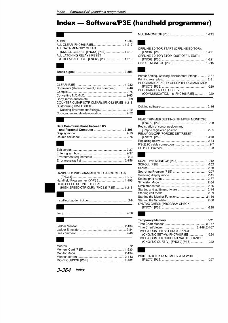
7/18/2019 Keyence Programming
http://slidepdf.com/reader/full/keyence-programming 388/392
I Starting edit mode .........................Starting the Monitor Function

7/18/2019 Keyence Programming
http://slidepdf.com/reader/full/keyence-programming 389/392
I n
d e x

7/18/2019 Keyence Programming
http://slidepdf.com/reader/full/keyence-programming 390/392
WARRANTIES AND DISCLAIMERS:
(1) KEYENCE warrants the Products to be free of defects in materials an
one (1) year from the date of shipment. If any models or samples were showsamples were used merely to illustrate the general type and quality of the Prthat the Products would necessarily conform to said models or samples. Antive must be shipped to KEYENCE with all shipping costs paid by Buyer or ospection and examination. Upon examination by KEYENCE, KEYENCE, at purchase price of, or repair or replace at no charge any Products found to bedoes not apply to any defects resulting from any action of Buyer, including binstallation, improper interfacing, improper repair, unauthorized modification,dling, such as exposure to excessive current, heat, coldness, moisture, vibra
nents which wear are not warranted. (2) KEYENCE is pleased to offer suggestions on the use of its various Prtions, and it is Buyer’s responsibility to ascertain the fitness of the Products fKEYENCE will not be responsible for any damages that may result from the (3) The Products and any samples (“Products/Samples”) supplied to Buyin humans, for human transportation, as safety devices or fail-safe systems, tions state otherwise. Should any Products/Samples be used in such a manKEYENCE assumes no responsibility, and additionally Buyer will indemnify KKEYENCE harmless from any liability or damage whatsoever arising out of aSamples. (4) OTHER THAN AS STATED HEREIN, THE PRODUCTS/SAMPLES AOTHER WARRANTIES WHATSOEVER. ALL EXPRESS, IMPLIED, AND SINCLUDING, WITHOUT LIMITATION, THE WARRANTIES OF MERCHANTPARTICULAR PURPOSE, AND NON-INFRINGEMENT OF PROPRIETARYDISCLAIMED. IN NO EVENT SHALL KEYENCE AND ITS AFFILIATED ENPERSON OR ENTITY FOR ANY DIRECT, INDIRECT, INCIDENTAL, PUNITQUENTIAL DAMAGES (INCLUDING, WITHOUT LIMITATION, ANY DAMAG
LOSS OF USE, BUSINESS INTERRUPTION, LOSS OF INFORMATION, LODATA, LOSS OF PROFITS, LOSS OF SAVINGS, THE COST OF PROCURGOODS, SERVICES OR TECHNOLOGIES, OR FOR ANY MATTER ARISTION WITH THE USE OR INABILITY TO USE THE PRODUCTS, EVEN IF AFFILIATED ENTITIES WAS ADVISED OF A POSSIBLE THIRD PARTY’S ANY OTHER CLAIM AGAINST BUYER. In some jurisdictions, some of the or damage limitations may not apply.
BUYER’S TRANSFER OBLIGATIONS: If the Products/Samples purchased
delivered to a third party, Buyer must provide such third party with a copy of tions, manuals, catalogs, leaflets and written information provided to Buyer pSamples.

7/18/2019 Keyence Programming
http://slidepdf.com/reader/full/keyence-programming 391/392
1 2 3
© KEYENCE CORPORATION, 1999 NKVP-UM-4-1000 Printed in Japan
Installation
1. Configuration andSpecifications
2. System Installation
3. Access Window
4. KV-D20 OperatorInterface Panel
5. KV-10/80 Hardware
6. Handheld Program-mer
7. KV-L2 Serial InterfaceModule
8. KV-AN6 Analog I/OModule
9. KV-AD4/DA4 AnalogI/O Unit
10. Troubleshooting
11. Appendices
Support
Software
1. Introduction
2. Editor
3. Simulator
4. Monitor
5. Appendices
Programming
1. Programming
2. Instructions
3. Interrupts
4. High-speed Counters
5. Positioning Control
6. Interrupts, High-speedCounters, PositioningControl
7. Serial Communication
8. ProgrammingExamples
INDEX
Specifications are subject to change without notice.
KEYENCE CORPORATION1-3-14, Higashi-Nakajima,Higashi-Yodogawa-ku,Osaka, 533-8555, JapanPHONE: 81-6-6379-2211FAX: 81-6-6379-2131
AFFILIATED COMPANIES
KEYENCE CORPORATION OF AMERICAPHONE: 201-930-0100 FAX: 201-930-0099
KEYENCE (UK) LIMITED
PHONE: 01908-696900 FAX: 01908-696777
KEYENCE DEUTSCHLAND GmbH
PHONE: 0711-79 73 71-0 FAX: 0711-797 77 99
KEYENCE FRANCE S.A.
PHONE: 01 47 92 76 76 FAX: 01 47 92 76 77
KEYENCE SINGAPORE PTE LTD.
PHONE: 392-1011 FAX: 392-5055
KEYENCE (MALAYSIA) SDN BHD
PHONE: 03-252-2211 FAX: 03-252-2131
KEYENCE (THAILAND) CO., LTD.
PHONE: 02-369-2777 FAX: 02-369-2775
KEYENCE THAIWAN CO., LTD.
PHONE: 02-2627-3100 FAX: 02-2798-8925
KEYENCE KOREA CORPORATION
PHONE: 02-563-1270 FAX: 02-563-1271

7/18/2019 Keyence Programming
http://slidepdf.com/reader/full/keyence-programming 392/392