Kenneth Harris State Oil and Gas Supervisor Division of...
32
July 12, 2017 Kenneth Harris State Oil and Gas Supervisor Division of Oil, Gas and Geothermal Resources 801 K Street, MS 18-05, Sacramento, CA 95814-3530 Fax: (916) 323-0424 Subject: California Underground Gas Storage Projects Rulemaking Dear Mr. Harris, The Environmental Defense Fund (EDF) and the Pipeline Safety Trust appreciates the opportunity to comment on the Division’s proposals for updating its gas storage regulations. As noted in EDF’s August 2016 comments 1 on the gas storage rule discussion draft, California has a unique opportunity to establish strong safety and environmental standards for gas storage facilities that not only would protect Californian communities but also provide insight for other federal and state jurisdictions considering revisions to their gas storage regulatory frameworks. California can set the example for the rest of the country, as it so often has on critical environmental issues – this draft shows the Division is on its way to doing so. The proposed rulemaking we are commenting on today has many commendable provisions, and is evidence of hard and thoughtful work on the part of DOGGR staff and leadership. In these comments, EDF and Pipeline Safety Trust (“the commenters”) will provide detailed thoughts and recommendations on the following topics: - Risk management planning - Emergency response planning - Records Management Program - Variances - Well construction - Mechanical Integrity testing protocols - Observation wells 1 See EDF comments on DOGGR gas storage discussion draft, August 2016, available at http://blogs.edf.org/energyexchange/files/2016/08/EDF-amended-comments-on-CA-gas-storage-discussion- draft-8-23-16.pdf.
Transcript of Kenneth Harris State Oil and Gas Supervisor Division of...

July 12, 2017
Kenneth Harris
State Oil and Gas Supervisor
Division of Oil, Gas and Geothermal Resources
801 K Street, MS 18-05, Sacramento, CA 95814-3530
Fax: (916) 323-0424
Subject: California Underground Gas Storage Projects Rulemaking
Dear Mr. Harris,
The Environmental Defense Fund (EDF) and the Pipeline Safety Trust appreciates the opportunity to
comment on the Division’s proposals for updating its gas storage regulations. As noted in EDF’s August
2016 comments1 on the gas storage rule discussion draft, California has a unique opportunity to
establish strong safety and environmental standards for gas storage facilities that not only would
protect Californian communities but also provide insight for other federal and state jurisdictions
considering revisions to their gas storage regulatory frameworks. California can set the example for the
rest of the country, as it so often has on critical environmental issues – this draft shows the Division is
on its way to doing so.
The proposed rulemaking we are commenting on today has many commendable provisions, and is
evidence of hard and thoughtful work on the part of DOGGR staff and leadership. In these comments,
EDF and Pipeline Safety Trust (“the commenters”) will provide detailed thoughts and
recommendations on the following topics:
- Risk management planning
- Emergency response planning
- Records Management Program
- Variances
- Well construction
- Mechanical Integrity testing protocols
- Observation wells
1 See EDF comments on DOGGR gas storage discussion draft, August 2016, available at http://blogs.edf.org/energyexchange/files/2016/08/EDF-amended-comments-on-CA-gas-storage-discussion-draft-8-23-16.pdf.

2
- Wellheads and valves
- Annular pressure monitoring
As a general matter, we recommend that DOGGR consult the Interstate Oil and Gas Compact
Commission and the Ground Water Protection Council’s “Underground Gas Storage Regulatory
Considerations,” a guide published in May 2017 designed to help state and federal regulators updating
their gas storage programs.2 DOGGR staff participated heavily in the production of the guide, and so we
hope these considerations strike DOGGR as both familiar and reasonable.
The remainder of our comments is divided into three parts: (1) a description of most of the revisions to
the proposed rule we are suggesting at this time and why these changes are critical; (2) a short list of
standalone edits; and (3) a redline incorporating the amendments we are suggesting today.
(1) In order to improve the efficiency and effectiveness of its gas storage regulations, the Division
should consider the following:
Risk management plan:
The proposed regulation’s Risk Management Planning program represents progress since last year’s
discussion draft. The commenters suggest additional changes designed to ensure that a company’s risk
management plan is properly adhered to at all levels of the company, from the CEO to the field staff.
Risk management plans (RMPs) are only effective when companies have done the following: developed
a policy that is supported by executive management and understood by all, established lines of
management responsibility and accountability, integrated the RMP into organizational processes,
provided for all required resources to support the RMP, initiated the RMP, provided for a continual
improvement framework, established open and transparent lines of communication within the entire
organization, applied RMP in all decision making and fully integrated the RMP into organizational
governance.
To that end, our proposed additions include (but are not limited to) provisions on resource allocation,
integration into the company’s processes, internal and external communication protocols, mechanisms
for continuous improvement, and a requirement to show that the company is in compliance with the
plan at all levels. These additions are drawn from industry standard practices on risk management,
including:
1. ANSI/ASSE/ISO 31000 (Z690.2-2011). Risk Management Principles and Guidelines (National
Adoption of: ISO 31000:2009)
2. ANSI/ASSE/ISO Guide 73 (Z690.1-2011). Vocabulary for Risk Management (National Adoption of:
ISO Guide 73:2009)
3. Risk Management-Guidance for the Implementation of ISO 31000
2 “Underground Gas Storage Regulatory Considerations: A Guide for State & Federal Regulatory Agencies,” States First Gas Storage Working Group, Interstate Oil and Gas Compact Commission and Groundwater Protection Council, May 2017, available at http://iogcc.ok.gov//Websites/iogcc/images/FINAL_UGS_report_2017-05.pdf.
3
4. ANSI/ASSE/ISO (Z690.3-2011). Risk Assessment Techniques (National Adoption of: IEC/ISO
31010:2009)
5. API Publication 761. Model Risk Management Plan Guide for Exploration and Production (E&P)
Facilities
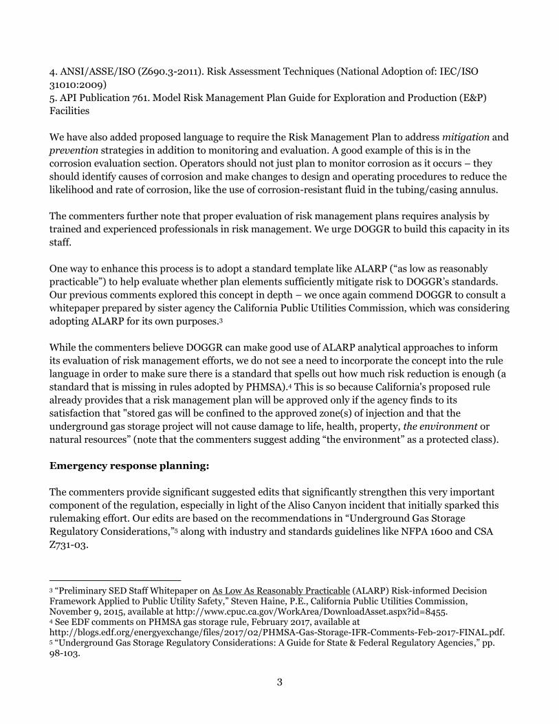
We have also added proposed language to require the Risk Management Plan to address mitigation and
prevention strategies in addition to monitoring and evaluation. A good example of this is in the
corrosion evaluation section. Operators should not just plan to monitor corrosion as it occurs – they
should identify causes of corrosion and make changes to design and operating procedures to reduce the
likelihood and rate of corrosion, like the use of corrosion-resistant fluid in the tubing/casing annulus.
The commenters further note that proper evaluation of risk management plans requires analysis by
trained and experienced professionals in risk management. We urge DOGGR to build this capacity in its
staff.
One way to enhance this process is to adopt a standard template like ALARP (“as low as reasonably
practicable”) to help evaluate whether plan elements sufficiently mitigate risk to DOGGR’s standards.
Our previous comments explored this concept in depth – we once again commend DOGGR to consult a
whitepaper prepared by sister agency the California Public Utilities Commission, which was considering
adopting ALARP for its own purposes.3
While the commenters believe DOGGR can make good use of ALARP analytical approaches to inform
its evaluation of risk management efforts, we do not see a need to incorporate the concept into the rule
language in order to make sure there is a standard that spells out how much risk reduction is enough (a
standard that is missing in rules adopted by PHMSA).4 This is so because California's proposed rule
already provides that a risk management plan will be approved only if the agency finds to its
satisfaction that "stored gas will be confined to the approved zone(s) of injection and that the
underground gas storage project will not cause damage to life, health, property, the environment or
natural resources” (note that the commenters suggest adding “the environment” as a protected class).
Emergency response planning:
The commenters provide significant suggested edits that significantly strengthen this very important
component of the regulation, especially in light of the Aliso Canyon incident that initially sparked this
rulemaking effort. Our edits are based on the recommendations in “Underground Gas Storage
Regulatory Considerations,”5 along with industry and standards guidelines like NFPA 1600 and CSA
Z731-03.
3 “Preliminary SED Staff Whitepaper on As Low As Reasonably Practicable (ALARP) Risk-informed Decision Framework Applied to Public Utility Safety,” Steven Haine, P.E., California Public Utilities Commission, November 9, 2015, available at http://www.cpuc.ca.gov/WorkArea/DownloadAsset.aspx?id=8455. 4 See EDF comments on PHMSA gas storage rule, February 2017, available at http://blogs.edf.org/energyexchange/files/2017/02/PHMSA-Gas-Storage-IFR-Comments-Feb-2017-FINAL.pdf. 5 “Underground Gas Storage Regulatory Considerations: A Guide for State & Federal Regulatory Agencies,” pp. 98-103.

4
The specificity required by the suggested edits would greatly increase the required rigor of emergency
response plans, with additional focus on training, education, drills, communication, plan updates, and
transparency.
Records Management Program:
The commenters suggest changing the required period for records retention from the lifetime of the
project to five years after decommissioning, providing for seamless handoff to subsequent operators or
the agency as appropriate. DOGGR should retain all records related to gas storage projects in perpetuity
– the information contained in these records could ultimately be vital to diagnosing and resolving any
potential subsurface issues in the future.
Variances: Throughout the proposed regulation, DOGGR leaves room for operators to propose
alternative measures. This is appropriate, as a facility’s particular circumstances may warrant a
different approach than that prescriptively required by the agency, and it allows for regulations to be
responsive to changes in technologies over time. As EDF stated in its previous comments, the rule
should articulate the standard by which such variances are approved. Some of the provisions in the
proposed regulation suggest a standard, but not all do. The gist of the standard should be that the
alternative approach is at least as effective and protective as the prescriptive approach provided in the
regulation (see, for example, our insertion in section (c) of the Well Construction Requirements).
Further, DOGGR should include in each well’s file a note articulating what variances have been granted
and providing evidence that shows that the variance meets the appropriate standard.
Well construction:
Our comments on well construction focus on three topics: the use of redundant master gate valves,
cementing requirements for surface and intermediate casing, and the use of corrosion inhibiting fluid in
the casing/tubing annulus.
The risk of losing well control is one of the greatest risks associated with California’s gas storage fields.
Redundant master gate valves should be the default configuration for each well. Without a redundant
wellhead design that allows for the ability to work on a well under pressure, an operator’s ability to
rapidly respond to an Aliso Canyon-type incident is quite limited. Currently, most gas storage wells in
California cannot be worked on under pressure – instead, operators must first kill the well through the
tubing and then disassemble the wellhead and install blowout preventers. Installation of a master gate
valve on the production casing that would allow for working on the well under pressure, eliminating the
risks of the more complicated procedure described above. This recommendation is consistent with
recommendations in the “Underground Gas Storage Regulatory Considerations.”6
The commenters inserted a proposed revision into the surface casing section requiring remediation if
cement fails to return to surface. This is a basic principle that would address one of the concerns around
SS-25 – that initial cementing was incomplete due to lost circulation. We also added a provision
6 Ibid., pp. 71-72 and p. 86.

5
requiring that intermediate casing used to isolate protected water be cemented to the surface, and
increased the required cement height above protected groundwater zones from 100 feet to 500 feet.
On the use of corrosion-inhibiting fluid in the casing/tubing annulus, we note that the proposed
regulation’s corrosion protocol is mostly focused on monitoring and mitigation, but is lacking a
provision that attempts to reduce the likelihood of corrosion in the first place! There is an extent to
which this topic is addressed in the Risk Management Planning process, but the commenters urge that
the use of corrosion-inhibiting fluid be a default requirement.
Our suggested redlines also include an adjustment to the variance process, as described above. In
particular the bar for a variance from the use of tubing and packer should be high, and DOGGR should
require considerable evidence from operators seeking such a variance that it is necessary and that the
alternative well configuration is at least as protective of safety and the environment.
Finally, the commenters look forward to DOGGR’s planned general well construction rule overhaul,
which would apply to gas storage wells in addition to production wells per the proposed subsection (d)
in the Well Construction Requirements section.
Mechanical Integrity testing protocols:
Ongoing testing of each gas storage well’s internal and external well integrity is crucial to preventing
future Aliso Canyon-type incidents.
We provide comments on both DOGGR’s internal and external MIT proposals. The comments focus on
the use of repeat sections, details related to casing thickness inspections, pressure tests for casing-only
wells, implications of lower testing pressures on operating pressures, approval of testing procedures,
and specific requirements for temperature surveying, noise logging, cement evaluation logging, and
remediation.
Repeat sections: the commenters provide a suggested redline calling for an appropriate repeat section
(generally 100' to 200' interval) to be run to verify log data accuracy and made a part of the log
presentation unless well conditions warrant otherwise.
Timing: the suggested redlines call for MIT Part I and II testing to occur prior to injection or
withdrawal. This will allow problems to be mitigated before operations occur.
Casing well thickness inspection: Corrosion is a significant problem associated with well integrity in the
underground gas storage fields in California. Elsewhere, the commenters have proposed edits to include
mitigation of corrosion in both the Risk Management Planning process and in the well construction
rules. On corrosion inspection, the proposed edits provide guidance as to how to conduct this test, how
to interpret the results, and thresholds for action.
Casing-only well pressure tests: because DOGGR’s rule allows casing-only injection under some
circumstances, the rule needs to address how to pressure test such wells. The proposed edits provide
such guidance.

6
Lowered pressure testing: we provide a recommendation for the circumstance when, with respect to
the pressure testing requirement, the Division allows for a lower testing pressure if necessary to ensure
that the testing does not compromise the mechanical integrity of the well. Provided that the test at the
lower pressure successfully demonstrates mechanical integrity, the Division should by administrative
order reduce accordingly the maximum operational pressure of the well. If a well cannot withstand
being tested at the existing maximum operating pressure, it should not be permitted to operate at that
pressure.
Approval: the commenters added a suggested edit that allows DOGGR an opportunity to approve of
testing procedures, beyond mere notification that certain tests are occurring. It is critical that tests be
run properly and with the correct purpose in order to yield useful results, and this provision would put
operators on notice that DOGGR is actively reviewing testing procedures to ensure useful outcomes.
Specific MIT Part II requirements: EDF recently commented on DOGGR’s Underground Injection
Control program discussion draft, which provides detailed requirements for the various tests that can
satisfy a showing of external mechanical integrity. Our suggested redline imports those requirements,
along with key additions necessary for the effectiveness of the tests.
Monitoring requirements / observation wells:
The suggested edits in this section provide detailed requirements for observation wells, including a
provision as to how they should be used, an explanation as to where they should be placed, and to what
standards they should be constructed. These edits are consistent with the considerations in the
“Underground Gas Storage Regulatory Considerations” referenced above.
We have also added a suggested requirement that operators submit a plan articulating which
monitoring protocols will be used (the proposed rule provides four possible methodologies, in addition
to allowing other possible methodologies), and requiring that observation wells be among them.
Finally, we have shortened the period by which operators must chemically fingerprint gas from surface
or cellar gas releases from 48 hours to 24 hours – time is of the essence in these situations.
Wellheads and valves:
In this section, the suggested redlines reiterate the need for redundant master gate valves, call for
testing at anticipated maximum operating pressures, reduce the time to repair inoperable valves from
90 days to 30, add guidelines around valve standards, and require concrete barriers or steel bollards to
be emplaced around all sides of the wellhead to act as barriers to protect the wellhead from potential
damage and release of gas. Each of these changes goes toward enhancing the integrity of the surface
equipment associated with gas storage wells, a critical safety barrier.
Annular pressure monitoring:

7
The commenters appreciates DOGGR’s addition of requiring monitoring of all annuli (even those
cemented to surface), and not just the production casing/tubing annulus. This small, inexpensive
addition is well worth the reduction in risk attained by this broadened monitoring requirement.
(2) Standalone changes found within the redline:
- Added a definition of buffer zone.
- Revising the requirement appearing throughout the proposed rule for operators to protect “life,
health, property and natural resources” to include “the environment.”
- Revisions to project data requirements, including proposed mechanical integrity testing
methodology.
- Addition to the casing diagram section (renamed “Wellbore Diagram”) to include reporting of
features that could compromise the ability to fully access the wellbore to depth.
- Requirement that wells with tubing and packer produce through tubing only.
- In a variety of sections (1726.6(d)(3)(E), 1726.7(e), and 1727.9(b)), added requirement that upon
discovery of serious problems (as defined by those sections), operators must shut in the well
unless doing so presents additional safety issues. As currently proposed, in many cases
operators must report the problems they find to the Division, but are not explicitly required to
take any direct action on the problematic well. This formulation would reduce the risk of
catastrophic releases.
It is worth noting that in addition to the items above, we have made a variety of other small edits for
clarity throughout the document, for which we urge due consideration.
(3) Track changes version of the proposed rule: See attached markup of proposed rule.
Thank you for this opportunity to comment on the gas storage rulemaking. EDF and the Pipeline Safety
Trust look forward to working with the Division over the coming months as it finalizes a robust
regulatory framework for natural gas storage. If you wish to follow up on any of the items discussed in
this letter or attachments, please feel free to contact us by email at [email protected], or by phone at 212-
616-1212.
Respectfully submitted,
Adam Peltz
Senior Attorney
Environmental Defense Fund
Rebecca Craven
Program Director
Pipeline Safety Trust
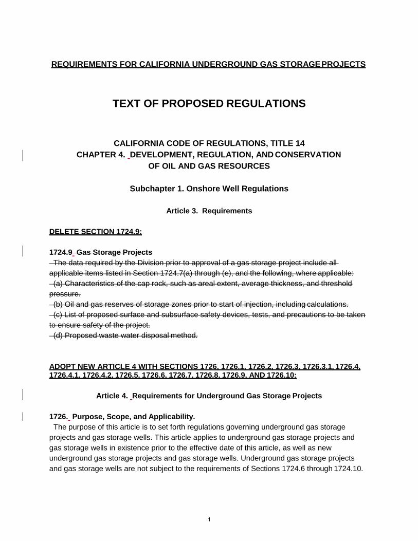
REQUIREMENTS FOR CALIFORNIA UNDERGROUND GAS STORAGE PROJECTS
TEXT OF PROPOSED REGULATIONS
CALIFORNIA CODE OF REGULATIONS, TITLE 14
CHAPTER 4. DEVELOPMENT, REGULATION, AND CONSERVATION
OF OIL AND GAS RESOURCES
Subchapter 1. Onshore Well Regulations
Article 3. Requirements
DELETE SECTION 1724.9:
1724.9 Gas Storage Projects
The data required by the Division prior to approval of a gas storage project include all
applicable items listed in Section 1724.7(a) through (e), and the following, where applicable:
(a) Characteristics of the cap rock, such as areal extent, average thickness, and threshold
pressure.
(b) Oil and gas reserves of storage zones prior to start of injection, including calculations.
(c) List of proposed surface and subsurface safety devices, tests, and precautions to be taken
to ensure safety of the project.
(d) Proposed waste water disposal method.
ADOPT NEW ARTICLE 4 WITH SECTIONS 1726, 1726.1, 1726.2, 1726.3, 1726.3.1, 1726.4, 1726.4.1, 1726.4.2, 1726.5, 1726.6, 1726.7, 1726.8, 1726.9, AND 1726.10:
Article 4. Requirements for Underground Gas Storage Projects
1726. Purpose, Scope, and Applicability.
The purpose of this article is to set forth regulations governing underground gas storage
projects and gas storage wells. This article applies to underground gas storage projects and
gas storage wells in existence prior to the effective date of this article, as well as new
underground gas storage projects and gas storage wells. Underground gas storage projects
and gas storage wells are not subject to the requirements of Sections 1724.6 through 1724.10.
1

AUTHORITY:
Note: Authority cited: Sections 3013, 3106 and 3180, Public Resources Code. Reference:
Section 3106, 3180, 3181, 3220 and 3403.5 Public Resources Code.
1726.1. Definitions.
(a) The following definitions are applicable to this article:
(1) “Area of review” means the three-dimensional extent of the reservoir used for
underground gas storage and surrounding areas that may be subject to its influence. The
area of review is delineated by the geologic extent of the reservoir such as impervious rock,
structural closure, decrease or loss of porosity and permeability, or hydrodynamic forces in a
three dimensional perspectiveimage.
(2) Confining strata“Caprock” means the rock layer or layers at the upper and lateral
boundariesyboundary of the storage reservoir acting as the primary barrier preventing upward
or lateral migration of fluids.
(3) “Fluid” means liquid or gas.
(4) “Gas storage well” means an active or idle well used primarily to inject or withdraw gas from
an underground gas storage project.
(5) “Reservoir” means the hydrocarbon reservoir that is being used or has been converted to store
natural gas in an underground gas storage project. The entire depth interval of a reservoir from
the shallowest to the deepest depth can be subdivided into one or more depth intervals, which
are referred to in this article as “zones”.
(6) “Underground gas storage project” means a project for the injection and withdrawal of natural
gas into an underground reservoir for the purpose of storage. An underground gas storage
project includes the reservoir used for storage, the confining stratacaprock, gas storage wells,
observation wells, and any other wells approved for use in the project. A gas storage project
also includes the wellheads and, to the extent that they are subject to regulation by the
Division, attendant facilities, and other appurtenances.
(7) “Buffer zone” means a protective boundary established around the gas storage area of
review to protect the integrity of the gas storage operations.
AUTHORITY:
Note: Authority cited: Sections 3013, 3106 and 3180, Public Resources Code. Reference:
Section 3106, 3180, 3220 and 3403.5 Public Resources Code.
1726.2 Approval of Underground Gas Storage Projects.
(a) A Project Approval Letter shall be obtained from the Division before any injection or
withdrawal occurs as part of an underground gas storage project. The Project Approval Letter
shall specify the location and nature of the underground gas storage project, as well as the
conditions of the Division’s approval. Changes to the operational parameters of an underground
gas storage project are subject to approval by the Division and shall be noted in either an
addendum to the Project Approval Letter or a revised Project Approval Letter. Underground gas
storage project operations shall not occur or continue unless consistent with the terms and
2

conditions of a current Project Approval Letter.
(b) The Division will review underground gas storage projects periodically, but not less than
once every three years, to verify adherence to the terms and conditions of the Project
Approval Letter, and will periodically review the terms and conditions of the Project Approval
Letter to ensure that they effectively prevent damage to life, health, property, and natural
resources. Project Approval Letters are subject to suspension, modification, or rescission by
the Division by Administrative Order.
(c) If the Division determines that operation of an underground gas storage project is
inconsistent with the terms and conditions of a current Project Approval Letter, or otherwise
poses a threat to life, health, property, or natural resources, then upon written notice by
Administrative Order from the Division specified operations shall cease immediately, or as
soon as it is safe to do so.
AUTHORITY:
Note: Authority cited: Sections 3013, 3106 and 3180, Public Resources Code. Reference:
Section 3106, 3180, 3220 and 3403.5 Public Resources Code.
1726.3 Risk Management Plans..
(a) For each underground gas storage project, the operator shall submit a project-specific
Risk Management Plan to the Division for review and approval. The Risk Management Plan
shall demonstrate to the Division’s satisfaction that stored gas will be confined to the approved
zone(s) of injection and that the underground gas storage project will not cause damage to life,
health, property, the environment or natural resources. In accordance with subdivision (b), the
Risk Management Plan shall evaluate threats and hazards associated with operation of the
underground gas storage project and identify prevention and mitigation protocols that
effectively address those threats and hazards. The Risk Management Plan shall also
specify a schedule for submitting updates to the risk assessment and prevention and mitigation
protocols to the Division. The Division may, in its discretion, require additional data,
additional risk assessment, or modification of prevention and mitigation protocols. The
Division will review the Risk Management Plan periodically, but not less than once every
three years. Risk assessment and prevention and mitigation protocols in the Risk
Management Plan shall be consistent with and additional to any other existing requirements. In
addition to process and procedure provisions in subdivision (b), the Risk Management Plan
shall establish an adequate framework to effectively support managing risks. At a minimum:
(1) The Plan shall articulate a policy wherein the organization’s leadership adequately addresses
its rationale for managing risk, Plan objectives, accountabilities, responsibilities, resource
allocation, how risk management performance will be measured, reported and reviewed. The
organization shall present evidence the Risk Management Plan and associated implementing
policy is well understood and executed by the entire organization.
(2) The Plan shall address and provide processes for adequate provision of all required resources
to execute the Plan. These will include but may not be limited to material, personnel and
training.
3

(3) The Plan shall exhibit how it is integrated into all of the organization’s processes.
(4) The Plan shall address processes that provide for robust internal and external communication
and reporting amongst risk owners, management, staff and those responsible and accountable
for organizational risk management.
(5) Processes and procedures shall be provided to ensure Plan monitoring, review and continual
improvement.
(6) Evidence shall be provided that risk management is applied in all decision making.
(1)(7) The Plan shall incorporate processes ensuring legal and regulatory compliance.
(b) The Risk Management Plan shall include a description of the methodology employed to
conduct the risk assessment and identify prevention and mitigation protocols, with references to
any third-party guidance followed in developing the methodology. The methodology shall
include at least the following:
(1) Identification of potential threats and hazards associated with operation of
the underground gas storage project;
(2) Evaluation of probability of threats, hazards, and consequences related to the events;
(3) Identification of possible prevention and mitigation protocols to reduce, manage
or monitor risks, including evaluation of the efficacy and cost-effectiveness of the
prevention and mitigation protocols;
(4) Selection and implementation of prevention and mitigation protocols;
(5) Documentation of the risk assessment process, including description of the basis
for selection of prevention and mitigation protocols;
(6) Data feedback and validation throughout the risk assessment process; and
(7) Regular, periodic risk assessment reviews to update information and evaluate the
effectiveness of prevention and mitigation protocols employed, which shall occur not less
than once every three years and also in response to changed conditions or new
information.
(c) In addition to the contents required in subdivision (b), all Risk Management Plans shall
include at least the following risk assessment and prevention and mitigation protocols:
(1) Well construction, cementing, and design standards, consistent with the requirements of
Section
1726.5 and including specification of the life expectancy of individual mechanical well barrier
elements. If the operator has gas storage wells that do not conform with the requirements of
Section 1726.5, then the Risk Management Plan shall include a work plan with time schedule for
either bringing the nonconforming wells into compliance or plugging and abandoning the wells
in accordance with Public Resources Code section 3208. The work plan shall include
prevention protocols for monitoring and testing each well that is not yet in compliance with the
requirements of Section 1726 so as to mitigate risks associated with the well to the extent
feasible.
(2) For each gas storage well, evaluation of whether installation employment of surface
and/or subsurface automatic or remote-actuated safety valves is appropriate based on
consideration of at least the following:
(A) The well’s distance from dwellings, other buildings intended for human occupancy,
4

or other well-defined outside areas where people may assemble such as campgrounds,
recreational areas, or playgrounds;
(B) Gas composition, operational pressures, total fluid flow, and maximum flow potential;
(C) The distance between wellheads or between a wellhead and other facilities, and
access availability for drilling and service rigs and emergency services;
(D) The risks created by installation and servicing requirements of safety valves;
(E) The risks to and from the well related to roadways, rights of way, railways, airports,
and industrial facilities;
(F) Proximity to environmentally or culturally sensitive areas;
(G) Alternative protection measures which could be afforded by barricades or distance
or other measures;
(H) Age of well;
(I) The risks of well sabotage;
(J) The current and predicted development of the surrounding area as reflected in the
local general plan,, topography and regional drainage systems and environmental
considerations;
(K) Topography and local wind patterns; and
(L) Evaluation of geologic hazards such as seismicity, active faults, landslides,
subsidence, and potential for tsunamis.
(3) A schedule for verification and demonstration of the external and internal mechanical
integrity of each well used in the underground gas storage project and any each well that
penetrates into or drilled through intersects the reservoir used for gas storage within the area of
review. The mechanical integrity testing protocols for gas storage wells shall, at a minimum,
adhere to the requirements of Section 1726.6.
(4) Corrosion prevention, mitigation, monitoring and evaluation including at least the following:
(A) Evaluation of tubular and casing integrity and identification of defects caused by
corrosion or other chemical or mechanical damage;
(B) Corrosion potential of wellbore produced fluids and solids, including the impact of
operating pressure on the corrosion potential of wellbore fluids and analysis of partial
pressures;
(C) Corrosion potential of annular and packer fluid;
(D) Corrosion potential of current flows associated with cathodic protection systems;
(E) Corrosion potential of all formation fluids, including fluids in formations above the
storage zone; and
(F) Corrosion potential of uncemented casing. (F)(G) Appropriate measures to prevent and mitigate all forms of corrosion that might
jeopardize well integrity.
(5) Ongoing monitoring of all casing pressure changes at the wellheads of gas storage wells,
analysis of facility flow erosion, hydrate potential, individual facility component capacity and
fluid disposal capability at intended gas and liquid rates and pressures, and analysis of the
specific impacts that the intended operating pressure range could have on the corrosive
potential of fluids in the system.
5

(6) Monitoring protocols in accordance with the requirements of Section 1726.7.
(7) Ongoing verification and demonstration of the integrity of the reservoir including
demonstration that reservoir integrity will not be adversely impacted by operating
conditions.
(8) Analysis and risk assessment of hazards associated with the formation of hydrates, and
scale from the well stream under various pressure, temperature, and flow rates, including
those beyond expected operating parameters.
(9) Analysis and risk assessment of geologic hazards including, and not limited to
seismicity, faults, subsidence, inundation by tsunamis, sea level rise, and floods.
(10) Analysis and risk assessment of hazards associated with the potential for explosion and/or fire.
(11) If observation wells are employed,installed, monitoring shall include identification and
documentation of baseline conditions such as wellbore pressure, pressure of monitored
annuli, gas composition and liquid level and geological formation being utilized for observation.
(11) (x) Protection of groundwater.
(12) Prioritization of risk mitigation efforts based on potential severity and estimated
likelihood of occurrence of each threat.
(13) Safety training for on-site personnel.
(14) An equipment maintenance program that includes training and proactive replacement
of equipment at risk of failure so as to ensure safe operation.
(15) An emergency response plan that at a minimum accounts for the threats and hazards
identified in the Risk Management Plan and that complies with the requirements of Section
1726.9.
(16) Requests for notice from land use agencies of local land use decisions that could affect
the Risk Management Plan, and providing notification to the Division of significant pending
land use decisions.
(d) The operator shall adhere to the risk mitigation protocols detailed in its Risk
Management Plan unless a variance has been approved by the Division in writing.
(e) The Division will provide completed Risk Management Plans and significant updates to
the Risk Management Plans to the California Public Utilities Commission and post them on the
Division’s public internet website. If any part of a Risk Management Plan is subject to
confidential treatment, then the Division will segregate the confidential records and only provide
them if the California Public Utilities Commission has agreed to treat the records as confidential.
AUTHORITY:
Note: Authority cited: Sections 3013, 3106 and 3180, Public Resources Code. Reference:
Section 3106, 3180, 3181, 3220 and 3403.5 Public Resources Code.
1726.3.1. Emergency Response Plan.
(a) The operator of an underground gas storage project shall have an Emergency Response
Plan (ERP) emergency response plan approved by the Division and ready for immediate
implementation. The emergency response plan shall address minimum guidelines regarding
6

emergency preparedness, response and management. The ERP shall apply to all levels of the
organization’s management, staff, outside emergency responders, regulatory agencies,
potentially affected communities and any other significant stakeholders. specify a schedule for
carrying out drills to validate the plan. The drills shall address the readiness of personnel and
their interaction with equipment including required third party service providers and their
current contact information. The operators shall provide local first responders at least 30 days
to review and provide input on the emergency response plan.
(b) The ERPemergency response plan shall at a minimum address the following regarding ERP planning activitiesscenarios:
(1) Clearly written and communicated ERP policy, goals and objectivesCollisions involving well heads;
(2) Plan design that identifies overall strategy, tactics, detailed risk assessment practices and a business impact analysisWell fires and blowouts;
(3) An appropriate-to-operation incident management system (IMS) designed to address resource management, communication systems, root cause analysis, incident documentation and performance indicators that measure response and recovery with respect to the ERP goals and objectives.
(4) A comprehensive hazard identification process that works in conjunction with the organization’s risk management plan. The organization shall provide documentation in the
ERP (or Risk Management Plan) that all appropriate operations and their potential consequences have been appropriately risk evaluated.
(5) Based upon the hazard identification and risk evaluation results, the ERP shall include appropriate preventative and mitigative strategies and tactics.
(2)(6) Plan design shall include well defined procedures to address potential emergency scenarios to include but not necessarily limited to:Hazardous material spills;
• Collisions involving wellheads as well as critical surface equipment
• Well fires, blowouts and explosions
• Hazardous material spills
• Equipment failures
• Natural disasters and related emergencies
• Surface and subsurface leaks or other well related failures; and
• Medical emergencies.
• Equipment failures;
• Natural disasters/emergencies;
(3) Leaks and well failures;
(4) Medical emergencies; and
Explosions.
(c) With respect to implementation, tThe ERPemergency response plan shall at a minimum, demonstrate and include all of the following:
(1) Detailed wWritten actions plans for all operational phases establishing assigned authority
to the appropriately trained andappropriate qualified person(s) at a facility for initiating effective
emergency response and control;
(2) Recordkeeping programs for all aspects of the operation and ERP;
(1)(3) Accident-response measures that outline response activities, leakage
7

mitigation approaches, and well control processes for well failure and full blowout
scenarios;
(4) Prepositioning, as feasible, and identification of all required resources in the form of
materials, facilities and personnel necessary to respond to all emergencies, including leaks
(including materials and equipment to respond to and stop the leak itself as well as to
protect public health), equipment failure, medical emergencies, fires, explosions, natural
disasters affecting operations or any other occurrence posing a threat to public safety, the
environment, or natural resource preservation;.
(5) The ERP shall include provisions for accurately assessing damage, responding
appropriately to such damage, and communicating adequately internally and externally. It
shall also contemplate appropriate procedures for incident termination and business
resumption if applicable;
(3) A schedule for regular drills, providing for an opportunity for involvement of the Division
and local first responders, and providing an opportunity for surprise drills initiated by local first
responders;
A schedule for regular evaluation and update of the emergency response plan;
(6) Protocols for emergency reporting and response to appropriate government agencies;
(7) Specification of personnel roles, and responsibilities and accountabilities;
(8) Internal and external communication protocol;
(9) All required eEmergency contact information including area codes; and
(10) A protocol for public notice of a large, uncontrollable leak to any potentially
impacted community, as defined in the risk management plan, if the leak cannot be
controlled within 24 hours of discovery by the operator.
(d) The ERP shall have a robust training and education program. The program shall at a minimum have clearly stated goals, objectives, training programs, testing standards and methods whereby organizational competency can be clearly demonstrated. Also, at a minimum, the program will address: (1) The type and frequency of training that will cover all applicable operational and emergency topics and conform to all regulatory requirements; (2) Specific training for outside agencies regarding pertinent facilities and operations; (3) Appropriate public education regarding the organization’s operations and ERP. The ERP must document all training. Such documentation shall be readily available for examination. (e)The ERP shall establish appropriate plans for ERP exercises, drills and plan improvement and update. At a minimum, the ERP shall incorporate the following considerations: (1) The ERP shall have a clear schedule for carrying out exercises and drills designed to validate the effectiveness of the organization’s ERP. (2) Drills shall be an appropriate combination of tabletop, workshops and field exercises (e.g., annual no-notice exercises) with all stakeholders participating. The drills and exercises shall
8

be designed to test all aspects of the plan and involve management, staff, regulators and all pertinent first responders. Drills shall combine specific operational functions as well as comprehensive drills covering a wide breadth of likely emergency scenarios. (3) First responders shall be included in the planning, development and evaluation of exercises and drills for informational purposes as well as providing critical professional input. (4) Drills and exercises shall be thoroughly evaluated after the fact for effectiveness and lessons learned by independent and objective parties, such as the organization’s audit department.
(f) The operator shall annually review and submit for Division approval an updated ERP to accommodate lessons learned, regulatory updates, organizational modifications, performance objective enhancements and changing environmental and operational conditions at a minimum. All updates shall incorporate an effective management of change process that engages all internal and external stakeholders that is timely and communicated clear.A protocol for public notice of a large, uncontrollable leak to any potentially impacted community, as defined in the risk management plan, if the leak cannot be controlled within 48 hours of discovery by the operator.
(f)(g) Subject to the California Public Records Act, the most current Emergency Response Plan shall be posted on a Division website.
AUTHORITY:
Note: Authority cited: Sections 3013, 3106 and 3180, Public Resources Code. Reference:
Section 3106, 3180, 3181, 3183, 3184 and 3403.5 Public Resources Code.
1726.4. Underground Gas Storage Project Data Requirements.
(a) For all underground gas storage projects, the operator shall provide the Division with data,
analysis, and interpretation that demonstrate to the Division’s satisfaction that stored gas will be
confined to the approved zone(s) of injection and withdrawal and that the underground gas
storage project will not cause damage to life, health, property, or natural resources. The
operator shall provide the data specified in this section and any data that, in the judgment of the
DivisionSupervisor, are pertinent and necessary for the proper evaluation of the proposed
project. The data provided by the operator shall be to a level of detail and certainty satisfactory
to the Division, and the operator shall ensure that required data is complete, current, and
accurate, regardless of the date of approval of the gas storage project. The data submitted to
the Division shall include at least the following:
(1) Oil and gas reserves of all proposed storage zones prior to start of injection, including
calculations, to indicate the storage capacity of the reservoir being considered for gas storage.
(2) Description of existing or proposed surface and subsurface safety devices, tests, and
precautions to be taken to ensure safety of the project.
(3) Proposed produced water disposal method. (1) (X) Methods for demonstration of external and integrity mechanical integrity of any existing
wells to be converted to gas storage.
(3)(4) Maximum and minimum reservoir pressure for the underground gas storage
project and the data and calculations supporting the bases for the pressure limits. Maximum
9
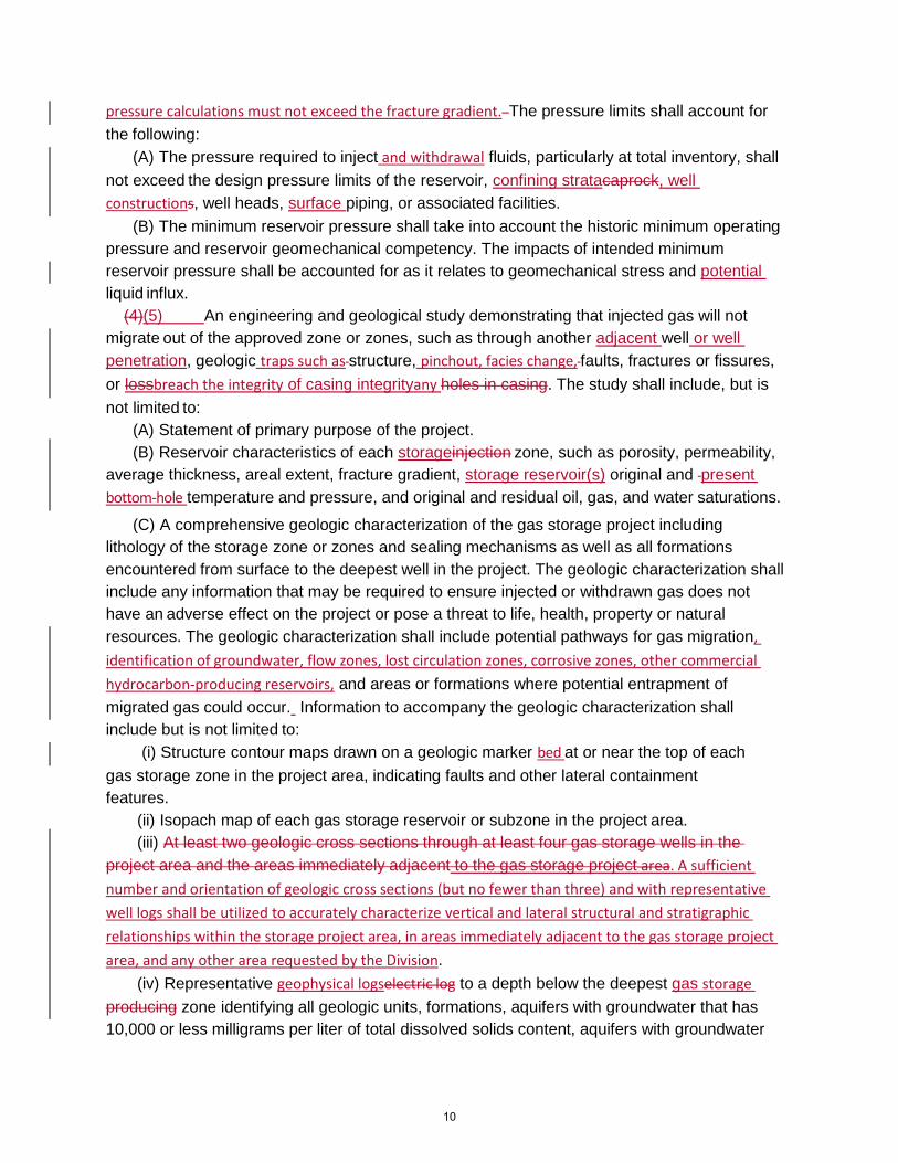
pressure calculations must not exceed the fracture gradient. The pressure limits shall account for
the following:
(A) The pressure required to inject and withdrawal fluids, particularly at total inventory, shall
not exceed the design pressure limits of the reservoir, confining stratacaprock, well
constructions, well heads, surface piping, or associated facilities.
(B) The minimum reservoir pressure shall take into account the historic minimum operating
pressure and reservoir geomechanical competency. The impacts of intended minimum
reservoir pressure shall be accounted for as it relates to geomechanical stress and potential
liquid influx.
(4)(5) An engineering and geological study demonstrating that injected gas will not
migrate out of the approved zone or zones, such as through another adjacent well or well
penetration, geologic traps such as structure, pinchout, facies change, faults, fractures or fissures,
or lossbreach the integrity of casing integrityany holes in casing. The study shall include, but is
not limited to:
(A) Statement of primary purpose of the project.
(B) Reservoir characteristics of each storageinjection zone, such as porosity, permeability,
average thickness, areal extent, fracture gradient, storage reservoir(s) original and present
bottom-hole temperature and pressure, and original and residual oil, gas, and water saturations.
(C) A comprehensive geologic characterization of the gas storage project including
lithology of the storage zone or zones and sealing mechanisms as well as all formations
encountered from surface to the deepest well in the project. The geologic characterization shall
include any information that may be required to ensure injected or withdrawn gas does not
have an adverse effect on the project or pose a threat to life, health, property or natural
resources. The geologic characterization shall include potential pathways for gas migration,
identification of groundwater, flow zones, lost circulation zones, corrosive zones, other commercial
hydrocarbon-producing reservoirs, and areas or formations where potential entrapment of
migrated gas could occur. Information to accompany the geologic characterization shall
include but is not limited to:
(i) Structure contour maps drawn on a geologic marker bed at or near the top of each
gas storage zone in the project area, indicating faults and other lateral containment
features.
(ii) Isopach map of each gas storage reservoir or subzone in the project area.
(iii) At least two geologic cross sections through at least four gas storage wells in the
project area and the areas immediately adjacent to the gas storage project area. A sufficient
number and orientation of geologic cross sections (but no fewer than three) and with representative
well logs shall be utilized to accurately characterize vertical and lateral structural and stratigraphic
relationships within the storage project area, in areas immediately adjacent to the gas storage project
area, and any other area requested by the Division.
(iv) Representative geophysical logselectric log to a depth below the deepest gas storage
producing zone identifying all geologic units, formations, aquifers with groundwater that has
10,000 or less milligrams per liter of total dissolved solids content, aquifers with groundwater
10

that has 3,000 or less milligrams per liter of total dissolved solids content, oil or gas zones, and
gas storage reservoirs.
(v) Additional information may be requested by the Division, and may include, but is not
limited to: additional isopachs, isogors, isobars, three-dimensional modeling, 2D or 3D
seismic reflection surveys, oil-water, gas-water, or oil- gas contact maps of the project, or
other information which would delineate significant known features such as faults and
fractures within the area of review for the underground gas storage project.
(D) Reservoir fluid data for each gas storage zone, such as oil gravity and viscosity,
water quality, presence and concentrations of non-hydrocarbon components in the
associated gas (e.g. hydrogen sulfide, helium, etc.), and specific gravity of gas.
(E) A map of the area of review and buffer zone showing the location and status of all wells
within and adjacent to the boundary of the area of review and buffer zone. The wellbore path
of directionally drilled wells shall be shown, with indication of the interval penetrating the gas
storage zone(s) of the underground gas storage project.
(F) Complete wellboreCasing diagrams, including all data specified in Section 1726.4.1, of
all wells that are within the area of review and that penetrate into or through the gas storage
reservoir are in the same or a deeper zone as the gas storage project, including directionally
drilled wells that intersect the area of review and buffer zone in the same or deeper zone. The
casing wellbore diagrams must demonstrate that the wells in the area of review and buffer zone
will not be a potential conduit for gas to migrate outside of the approved zone of gas storage or
otherwise have an adverse effect on the project or cause damage to life, health, property, or
natural resources. At a minimum, the wellbore casing diagrams and well records must
demonstrate that plugged and abandoned wells have cement across all perforations (or open-
hole interval) and extending at least 100 feet above the highest of the top of a landed liner, the
uppermost perforations, the casing cementing point, the water shutoff holes, or the intended
zone of injection.
(G) Identification of all wells within the area of review and buffer zone that are not in the
same or a deeper zone as the underground gas storage project, including description of the
total depth of the well and the estimated top of the gas storage reservoir below the well total
depth.
(H) Wells completed ininto or penetrating through the intended gas storage reservoir shall
be identified and evaluated for containment assurance for the design of gas storage operation
volumes, pressures, and flow rates. The operator should shall identify, and the Division confirm,
wells which may require integrity testing or well geophysical logging in order to meet the
integrity demonstration. The Division may select plugged and abandoned wells to be re-
entered, examined, re-plugged and abandoned, or monitored to manage identified
containment assurance issues prior to approval of gas storage operations.
(I) The planned or estimated well drilling and plugging and abandonment program to
complete the project, showing all gas storage wells, plugged and abandoned wells, other wells
related to the project, and unit boundaries.
(J) Maps of the locations of underground disposal wells and disposal zoneshorizons, mining,
and other subsurface industrial activities not associated with oil and gas production or gas
11

storage operations within the area of review and buffer zone, to the extent it is publicly
available.
(5)(6) A gas storage injection and withdrawal plan that includes at least the following:
(A) Maximum anticipated surface injection and withdrawal pressures and maximum
anticipated and daily rate of injection and/or withdrawal, by well.
(B) Monitoring system or method acceptable to the Division to be utilized to ensure the gas
injected is confined to the intended approved zone(s) of injection.
(C) A wellhead monitoring system acceptable to the Division for the detection of leaks and monitoring of pressures.
(D) A list of proposed cathodic protection measures where employed.
(E) A summary of the source and analysis of the gas injected, submitted to the Division on
an annual basis.
(6)(7) The name and API number of all gas storage wells and other wells that are
part of the underground gas storage project.
(7)(8) Any data that, in the judgment of the Division, are pertinent and necessary for
the proper evaluation of the underground gas storage project.
(b) Updated data shall be provided to the Division if there are changes in operating conditions,
such as gas plant or compressor changes, or if more accurate data become available, such as
updated cross sections, new reservoir characteristics data, or new pressure flow modeling.
(c) All data filed with the Division under this section shall be submitted electronically, in a
format acceptable to the Division. All maps, diagrams and exhibits shall be clearly labeled as to
scale, north arrow, coordinate system, and purpose, and shall clearly identify wells, boundaries,
zones, contacts, and other relevant data.
(d) Where it is infeasible to supply the data specified in subdivision (a), the Division may
accept alternative data that demonstrate to the Division’s satisfaction that injected gas will be
confined to the approved reservoir or reservoirs of injection and that the underground gas
storage project will not cause damage to life, health, property, the environment, or natural
resources. Such data shall meet the minimum standards of the intent of subdivision (a).
(e) The operator shall consult with the Division if the operator believes that there is a basis
under state or federal law for confidential treatment of any data submitted to the Division. If the
Division agrees that there is a basis for confidential treatment of data submitted, then the
Division will take appropriate steps to maintain the confidentiality of that data.
12

(f) The Division will make all data received under this section available to the California Public
Utilities Commission upon request. If the requested records are subject to confidential
treatment per the California Public Records Act or relevant federal law, then the Division will
only provide the records if the California Public Utilities Commission has agreed to treat the
records as confidential.
AUTHORITY:
Note: Authority cited: Sections 3013, 3180 and 3106, Public Resources Code. Reference:
Section 3106, 3180, 3181, 3220 and 3403.5 Public Resources Code.
1726.4.1. WellboreCasing Diagrams.
(a) Wellbore Casing diagrams submitted under Section 1726.4 shall adhere to the
following requirements:
(1) Wellbore Casing diagrams shall at a minimum include all of the following data:
(A) Operator, lease name, well number, and API number of the well;
(B) Ground elevation from sea level;
(C) Reference elevation (i.e. rig floor or Kelly Bushing);
(D) Base of groundwater that has 3,000 or less milligrams per liter of total dissolved solids
content;
(E) Base of groundwater that has 10,000 or less milligrams per liter of total dissolved solids
content;
(F) Sizes, weights, grades, and connection types of casing and tubing;
(G) Details on associated equipment such as surface and subsurface safety valves,
packers, gas lift mandrels;
(H) Depths of casing shoes, stubs, and liner tops;
(I) Depths of perforation intervals, open-hole completions, water shutoff holes, cement port,
cavity shots, cuts, patches, casing damage, top of junk or fish left in well, and any other feature
that influences flow in the well or may compromise the mechanical integrity of the well or the
ability to fully access the wellbore to total depth;
(J) Hole size diameter and depth of drilled hole;
(K) Cement plugs inside casings, including top and bottom of cement plug, with method of
determination;
(L) All cement fill behind casings, including top and bottom of cemented interval, with
method of determination;
(M) Type and density of fluid between cement plugs;
(N) Depths and names of the formation(s), zone(s), and geologic markers beds penetrated
by the well, including the top and bottom of the gas storage zone(s) and the top and bottom of
the confining zonecaprock;
(O) All information used to calculate the cement slurry (volume, density, yield), including but
not limited to, cement type and additives, for each cement job; and
(P) All of the information listed in this paragraph for all previous drilled or sidetracked well
bores.
13

(2) Measured depth and true vertical depth shall be provided for all measurements required
under subdivision (a)(1).
(3) For directionally drilled or horizontal wells, a directional survey shall be provided
with inclination, azimuth measurements, and surface and bottomhole location.
(4) Wellbore Casing diagrams shall be submitted in an electronic format acceptable to the Division.
(5) For all wells to be used for gas injection and/or withdrawal, the wellbore casing diagram
shall include the mechanical well barrier elements that comprise the primary and secondary
barriers as specified in section 1726.5.
AUTHORITY:
Note: Authority cited: Sections 3013, 3106 and 3180, Public Resources Code. Reference:
Section 3106, 3180, 3181, 3220 and 3403.5 Public Resources Code.
1726.4.2. Records Management.
(a) The operator of an underground gas storage project shall establish a Records Management
Program to ensure documentation of essential information is created, maintained, protected,
and retrievable when needed. The operator shall submit its Records Management Plan to the
Division for review and approval.
(b) The Records Management Program shall identify all records related to evidence of conformity
to the requirements in this article as essential, and these records shall be maintained for a
period of 5 years after the decommissioning of the lifetime of the project. Provisions shall be
made for the secure archival of all records associated with the project and seamless handoff of
all records to potential subsequent operators of the project or to the Division, as applicable.
(c) The Records Management Program shall establish a filing and storage strategy that ensures
records are accessible and protected against environmental damage. Records may exist in
many different formats and shall be managed according to the format in which they are
maintained. Records may be protected following a graded approach, commensurate with the
value of the record and the cost to reproduce the information.
(d) The Records Management Program shall establish a process for tracking records throughout
their entire information life cycle so that it is clear at all times where a record exists, which is
the most current version of the record, and the history of change or modification of the record.
(e) The Records Management Program shall allow for prompt retrieval and production of
records upon request from the Division.
AUTHORITY:
Note: Authority cited: Sections 3013, 3106 and 3180, Public Resources Code. Reference:
Section 3106, 3181, 3220 and 3403.5 Public Resources Code.
14

1726.5. Well Construction Requirements.
(a) Operators shall design, construct or convert, and maintain gas storage wells to effectively
ensure mechanical integrity under anticipated operating conditions for the underground gas
storage project. The operator shall ensure that a single point of failure does not pose an
immediate threat of loss of control of fluids and make certain that integrity concerns with a gas
storage well are identified and addressed before they can become a threat to life, health,
property, the environment or natural resources.
(b) Operators can demonstrate that a gas storage well adheres to the performance standard
in subdivision (a) by demonstrating all of the following:
(1) The well has been completed with both primary and secondary mechanical well barriers
to isolate the storage gas within the storage reservoir and transfer storage gas from the
surface into and out of the storage reservoir.
(A) The primary mechanical barrier is the barrier that is exposed to the withdrawal or
injection flow stream. The primary mechanical barrier shall be able to withstand full
operating pressure as demonstrated by periodic pressure testing and through annular
pressure monitoring. An example of a well configuration that meets the minimum
requirements for a primary mechanical barrier is a well configuration that includes:
(i) A Christmas tree master valvewell assembly with master gate valves on both tubing and on production casing;
(ii) Casing and Ttubing hanger with seals;
(iii) Injection or production Production tubing with packer that allows for only gas production through tubing; and
(iv) A production packer.A corrosion resistant fluid-filled casing/tubing annulus.
(B) The secondary mechanical barrier is not exposed to the withdrawal or injection flow
stream under normal operations. The secondary mechanical barrier shall be able to
withstand full operating pressure as demonstrated by periodic annular pressure testing and
casing evaluation logs. In the event of a primary mechanical barrier failure, the secondary
mechanical barrier shall be able to contain the leaking fluids until the primary mechanical
barrier is re- established. An example of a well configuration that meets the minimum
requirements for a secondary mechanical barrier is a well configuration that includes:
(i) Wellhead components and master gate valves, including casing hanger and seal
assembly; and
(ii) Production and/or Intermediate Casing.
(2) Each string of casing is designed to safely contain the expected internal and
external operating pressures and tensile loads.
(3) The surface casing is of sufficient size, weight, grade, competency, and depth, and
cemented to the surface to support subsequent drilling and injection/production operations.
(3)(4) Intermediate casing must be set to protect groundwater if surface casing was
set above the base of protected groundwater, and/or if additional protected groundwater was
found below the surface casing shoe.
(4)(5) The production casing is of sufficient size, weight, grade, competency, and
depth, and properly cemented, to maintain the well integrity, and is compatible with well and
15

operational fluid chemical composition. The production casing is designed to accommodate
fluids on injection and withdrawal at the maximum expected o p e r a t i o n a l pressures and
velocities. The production casing shall be is free of open perforations or holes other than the
planned completion interval(s). Perforations created for investigative or remedial work are
sealed with cement and pressure tested to establish hydraulic isolation.
(5)(6) Casing connections are appropriate for use in the well design and exceed the
expected mechanical loads.
(6)(7) The gas storage well is cemented so as to maintain the integrity of the storage
zone(s) by providing isolation of the reservoir from communication with other sources of
permeability or porosity throughoutthrough the wellbore. Isolation is accomplished by filling
the annular space between the casing and formation with competent cement to create a seal
so that communication of fluids from the storage zone or other zones of interest is prevented.
(7)(8) The cementing operations used a cement slurry designed for the anticipated
wellbore conditions and operational pressures. All casing was cemented in a manner that
ensures proper distribution and bonding of cement in the annular spaces. Additionally,
cementing operations meet or exceed the following requirements:
(A) Surface casing is cemented with sufficient cement to fill the annular space from the
casing shoe to the surface to protect ground water. If full circulation of cement is not achieved
or cement falls back, the annular space shall be topped off with cement from the surface to
provide a competent cement sheath from the shoe to the surface.
(B) When intermediate casing is installed to protect groundwater, the operator shall set a full
string of new intermediate casing to a minimum depth of at least 100 feet below the base of
the deepest strata containing protected groundwater and cement to the surface. Intermediate
casing not used to protect groundwater and production casings, if not cemented to the
surface, are cemented with sufficient cement to fill the annular space to at least 500 feet
above the gas storage reservoir, oil and gas zones or anomalous pressure intervals and to at
least 100 500 feet above the base of groundwater that has 3,000 or less milligrams per liter of
total dissolved solids content.
(8)(9) Cement plugs provide for effective zonal isolation.
(9)(10) Any remedial cement slurry or other sealants and placement techniques are
designed for the specific wellbore conditions, formations, pressures, and type of repairs.
(10)(11) Cement bond log or cement evaluation logs acceptable to the Division is on file
that indicates an adequate cement bond between the casing, cement and geologic formations.
A competent cement bond providing hydraulic isolation extends across the confining
zonecaprock, and at least 100 feet above the gas storage reservoir.
(11)(12) For wells equipped with tubing and packer, packer shall be is set in a
cemented section of the production casing within confining zonecaprock or at a location
acceptable to the Division.
(c) If the operator does not demonstrate that a gas storage well meets the criteria of
subdivision (b), then the operator shall demonstrate to the Division’s satisfaction that an
alternative method of well design and construction has been employed that effectively
16

adheres to or exceeds the performance standard of subdivision (a) and is at least as effective
and protective as the requirements specified in subdivision (b). The Division will determine on a
case-by-case basis whether the operator has effectively demonstrated that a gas storage
well that does not conform to the criteria in subdivision (b) meets the performance standard
in subdivision (a).
(d) The requirements of this section are in addition to all other well construction
requirements of this chapter.
AUTHORITY:
Note: Authority cited: Sections 3013, 3106 and 3180, Public Resources Code. Reference:
Section 3106, 3180, 3220 and 3403.5 Public Resources Code.
1726.6 Mechanical Integrity Testing.
(a) The operator shall, at a minimum, conduct the following internal mechanical integrity
testing on each gas storage well and every other well that penetrates the gas storage reservoir
of the operator’s underground gas storage project, with the exception of wells that have been
plugged and abandoned in accordance with Public Resources Code section 3208: Logging
shall be conducted according to industry or Division standards, whichever is more
comprehensive, and include repeat sections of no less than 200 feet unless well conditions
preclude.
(1) A temperature and noise log shall be conducted at least annually to ensure integrity.
All anomalies identified shall be immediately reported to the appropriate district office and
explainedexplained to the Division’s satisfaction. If the operator is unable to explain any
anomaly to the Division’s satisfaction, then the well shall not be used for injection or
withdrawal without subsequent approval from the Division.
(1) A Casing Wall Thickness Inspection log shall be conducted on each gas storage well
to evaluate corrosion potential employing such methods as magnetic flux and ultrasonic
technologies, and shall be performed at least once every 24 months to determine if there are
possible issues with production casing. The Casing Wall Thickness Inspection of the well
shall measure the thickness of the external casing of a well, as well as the amount of any
corrosion that has occurred to that casing, and shall be compared against prior result and
any other available data to determine the corrosion rate. T o c o n d u c t t h i s t e s t , the
tubing shall be removed from the entire depth of the well and measurements are taken
directly from the inside wall of the casing. If the inspection reveals thinning of the casing, the
current strength of the casing will be calculated. If the current strength of the casing has
diminished to the point that it cannot withstand authorized operating pressures for the well
plus a built-in additional safety factor of pressure, the well has failed this test. The well shall
be remediated and shall not be used for injection or withdrawal without subsequent approval
from the Division. A passing test for a Casing Wall Thickness Inspection would show no
thinning of the casing that diminishes the casing’s ability to contain at least 115% of the
well's maximum allowable operating pressure. The Division may approve a less frequent
casing wall thickness inspection schedule for a well if the operator demonstrates to the
Division’s satisfaction that the well’s corrosion rate is low enough that biennial inspection is
17
not necessary.
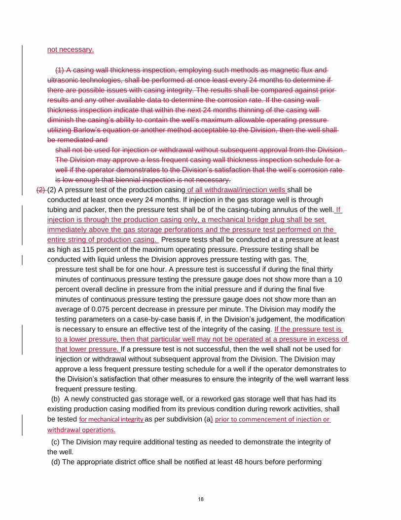
(1) A casing wall thickness inspection, employing such methods as magnetic flux and
ultrasonic technologies, shall be performed at once least every 24 months to determine if
there are possible issues with casing integrity. The results shall be compared against prior
results and any other available data to determine the corrosion rate. If the casing wall
thickness inspection indicate that within the next 24 months thinning of the casing will
diminish the casing’s ability to contain the well’s maximum allowable operating pressure
utilizing Barlow’s equation or another method acceptable to the Division, then the well shall
be remediated and
shall not be used for injection or withdrawal without subsequent approval from the Division.
The Division may approve a less frequent casing wall thickness inspection schedule for a
well if the operator demonstrates to the Division’s satisfaction that the well’s corrosion rate
is low enough that biennial inspection is not necessary.
(2) (2) A pressure test of the production casing of all withdrawal/injection wells shall be
conducted at least once every 24 months. If injection in the gas storage well is through
tubing and packer, then the pressure test shall be of the casing-tubing annulus of the well. If
injection is through the production casing only, a mechanical bridge plug shall be set
immediately above the gas storage perforations and the pressure test performed on the
entire string of production casing. Pressure tests shall be conducted at a pressure at least
as high as 115 percent of the maximum operating pressure. Pressure testing shall be
conducted with liquid unless the Division approves pressure testing with gas. The
pressure test shall be for one hour. A pressure test is successful if during the final thirty
minutes of continuous pressure testing the pressure gauge does not show more than a 10
percent overall decline in pressure from the initial pressure and if during the final five
minutes of continuous pressure testing the pressure gauge does not show more than an
average of 0.075 percent decrease in pressure per minute. The Division may modify the
testing parameters on a case-by-case basis if, in the Division’s judgement, the modification
is necessary to ensure an effective test of the integrity of the casing. If the pressure test is
to a lower pressure, then that particular well may not be operated at a pressure in excess of
that lower pressure. If a pressure test is not successful, then the well shall not be used for
injection or withdrawal without subsequent approval from the Division. The Division may
approve a less frequent pressure testing schedule for a well if the operator demonstrates to
the Division’s satisfaction that other measures to ensure the integrity of the well warrant less
frequent pressure testing.
(b) A newly constructed gas storage well, or a reworked gas storage well that has had its
existing production casing modified from its previous condition during rework activities, shall
be tested for mechanical integrity as per subdivision (a) prior to commencement of injection or
withdrawal operations.
(c) The Division may require additional testing as needed to demonstrate the integrity of
the well.
(d) The appropriate district office shall be notified at least 48 hours before performing
18

mechanical integrity testing so that Division staff may have an opportunity to approve and
witness the testing. All mechanical integrity testing shall be documented and copies of test
results shall be submitted to the Division in an electronic format within 30 days.
AUTHORITY:
Note: Authority cited: Sections 3013, 3106 and 3180, Public Resources Code. Reference:
Section 3106, 3180, 3181, 3220 and 3403.5 Public Resources Code.
1726.6.2 Mechanical Integrity Testing Part Two – Fluid Migration Behind Casing,
Tubing or Packer
(a) In addition to internal mechanical integrity testing described in section 1726.6.1, additional
testing is required to demonstrate that there is no fluid migration behind the casing, tubing, or
packer. This testing may be accomplished by any of the methods set forth in this section, or other
methods approved by the Division. Operators shall obtain written approval from the appropriate
Division district office regarding the testing method prior to performing the tests. Testing
required under this section must be performed prior to the commencement of injection.
Thereafter, injection wells shall be tested at least once each year, or on a testing schedule
approved by the Division based upon consideration of the age of the well, geology, and
operational factors. Testing required under this section shall also be performed following any
significant (as defined with the risk assessment process in the Risk Management Plan) anomalous
rate or pressure change, or whenever requested by the Division.
(A) Temperature Survey. A temperature survey performed to satisfy the requirements of this
section shall adhere to the following:
(1) The well must be taken off injection at least twenty-four hours but not more than forty-
eight hours prior to performing the temperature log, unless an alternate duration has been approved
by the Division.
(2) All casing and all internal annuli must be completely filled with fluid and allowed to stabilize
prior to commencement of logging operations.
(3) The logging tool shall be centralized, and calibrated.
(4) The well must be logged from the surface downward, lowering the tool at a rate of no more
than thirty feet per minute.
(5) If the well has not been taken off injection for at least twenty-four hours before the log is run,
comparison with either a second log run six hours after the time the log of record is started or a log
from another well at the same site showing no anomalies shall be available to demonstrate normal
patterns of temperature change.
(6) The log data shall be provided to the Division electronically in either LAS or ASCII format.
(B) Noise Log. A noise log performed to satisfy the requirements of this section shall adhere to
the following:
(1) Noise logging may not be carried out while injection is occurring.
(2) All casing and all internal annuli must be completely filled with fluid and allowed to stabilize
19
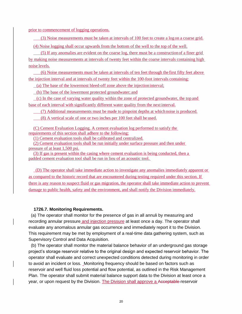
prior to commencement of logging operations.
(3) Noise measurements must be taken at intervals of 100 feet to create a log on a coarse grid.
(4) Noise logging shall occur upwards from the bottom of the well to the top of the well.
(5) If any anomalies are evident on the coarse log, there must be a construction of a finer grid
by making noise measurements at intervals of twenty feet within the coarse intervals containing high
noise levels.
(6) Noise measurements must be taken at intervals of ten feet through the first fifty feet above
the injection interval and at intervals of twenty feet within the 100-foot intervals containing:
(a) The base of the lowermost bleed-off zone above the injection interval;
(b) The base of the lowermost protected groundwater; and
(c) In the case of varying water quality within the zone of protected groundwater, the top and
base of each interval with significantly different water quality from the next interval.
(7) Additional measurements must be made to pinpoint depths at which noise is produced.
(8) A vertical scale of one or two inches per 100 feet shall be used.
(C) Cement Evaluation Logging. A cement evaluation log performed to satisfy the
requirements of this section shall adhere to the following:
(1) Cement evaluation tools shall be calibrated and centralized.
(2) Cement evaluation tools shall be run initially under surface pressure and then under
pressure of at least 1,500 psi.
(3) If gas is present within the casing where cement evaluation is being conducted, then a
padded cement evaluation tool shall be run in lieu of an acoustic tool.
(D) The operator shall take immediate action to investigate any anomalies immediately apparent or
as compared to the historic record that are encountered during testing required under this section. If
there is any reason to suspect fluid or gas migration, the operator shall take immediate action to prevent
damage to public health, safety and the environment, and shall notify the Division immediately.
1726.7. Monitoring Requirements.
(a) The operator shall monitor for the presence of gas in all annuli by measuring and
recording annular pressure and injection pressure at least once a day. The operator shall
evaluate any anomalous annular gas occurrence and immediately report it to the Division.
This requirement may be met by employment of a real-time data gathering system, such as
Supervisory Control and Data Acquisition.
(b) The operator shall monitor the material balance behavior of an underground gas storage
project’s storage reservoir relative to the original design and expected reservoir behavior. The
operator shall evaluate and correct unexpected conditions detected during monitoring in order
to avoid an incident or loss. Monitoring frequency should be based on factors such as
reservoir and well fluid loss potential and flow potential, as outlined in the Risk Management
Plan. The operator shall submit material balance support data to the Division at least once a
year, or upon request by the Division. The Division shall approve a Acceptable reservoir
20
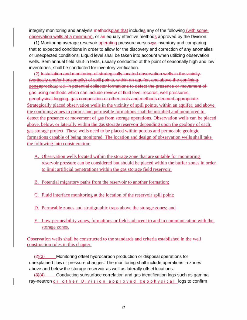
integrity monitoring and analysis methodsplan that includes any of the following (with some
observation wells at a minimum), or an equally effective methods approved by the Division:
(1) Monitoring average reservoir operating pressure versus gas inventory and comparing
that to expected conditions in order to allow for the discovery and correction of any anomalies
or unexpected conditions. Liquid level shall be taken into account when utilizing observation
wells. Semiannual field shut-in tests, usually conducted at the point of seasonally high and low
inventories, shall be conducted for inventory verification.
(2) Installation and monitoring of strategically located observation wells in the vicinity
(vertically and/or horizontally) of spill points, within an aquifer, and above the confining
zoneaprockcaprock in potential collector formations to detect the presence or movement of
gas using methods which can include review of fluid level records, well pressures,
geophysical logging, gas composition or other tools and methods deemed appropriate.
Strategically placed observation wells in the vicinity of spill points, within an aquifer, and above
the confining zones in porous and permeable formations shall be installed and monitored to
detect the presence or movement of gas from storage operations. Observation wells can be placed
above, below, or laterally within the gas storage reservoir depending upon the geology of each
gas storage project. These wells need to be placed within porous and permeable geologic
formations capable of being monitored. The location and design of observation wells shall take
the following into consideration:
A. Observation wells located within the storage zone that are suitable for monitoring
reservoir pressure can be considered but should be placed within the buffer zones in order
to limit artificial penetrations within the gas storage field reservoir;
B. Potential migratory paths from the reservoir to another formation;
C. Fluid interface monitoring at the location of the reservoir spill point;
D. Permeable zones and stratigraphic traps above the storage zones; and
E. Low-permeability zones, formations or fields adjacent to and in communication with the
storage zones.
Observation wells shall be constructed to the standards and criteria established in the well
construction rules in this chapter.
(2)(3) Monitoring offset hydrocarbon production or disposal operations for
unexplained flow or pressure changes. The monitoring shall include operations in zones
above and below the storage reservoir as well as laterally offset locations.
(3)(4) Conducting subsurface correlation and gas identification logs such as gamma
ray-neutron o r o t h e r D i v i s i o n a p p r o v e d g e o p h y s i c a l logs to confirm
21

the location of gas being injected into the intended storage reservoir, as needed.
(c) The operator shall immediately report to the Division any instance of a surface or cellar
gas release of any size, in any location within the area of review or buffer zone of the
underground gas storage project. The operator shall chemically fingerprint the gas from such
a release within 48 24 hours of detection, and the operator shall provide the results of the gas
analysis to the Division as soon as they are available.
(d) The operator of an underground gas storage project shall employ a real-time data
gathering system, such as Supervisory Control and Data Acquisition, by January 1, 2020. At a
minimum, the real-time data gathering system shall be deployed and utilized in accordance
with the following requirements:
(1) The real-time data gathering system shall include pressure sensors for every casing
annulus and tubing and data transmissiontted to an operations monitoring center.
(2) The real-time data gathering system shall have alarms set for each annulus to monitor for
pressure indicative of potential leaks or potential migration of gas. The alarms shall alert the
operations monitoring center if pressure exceeds preconfigured set points. For tubing, the
alarm set point shall not be higher than the maximum allowable surface pressure. For the
annulus annuli between production casing and tubing, the alarm set point shall be determined
based on annular fluid, the initial pressure when the packer was set, and operational
configuration. For strings without any anticipated surface pressure, such as surface or
intermediate casings, the alarm set point shall not be higher than 100 psi.
(3) If sustained casing pressure above 100 psi is believed to be caused by shallow gas or
other fluid migration, then the operator shall do the following:
(A) The operator shall first bleed off annular pressure and track pressure and time for
the well to build-up pressure back to equilibrium pressure.
(B) Next, the operator shall sample the fluids building up in the annulus and confirm that
the accumulation is not due to migration of storage gas by performing chemical finger printing
or other diagnostic tests approved by the division.
(C) If the diagnostic testing under paragraphs (A) and (B) confirm that the pressure build
up is not due to migration of storage gas, the operator shall propose an alarm set point to the
Division that is no greater than 100 psi above the equilibrium pressure, unless such pressure
would pose a risk to casing integrity. The operator’s proposal shall at a minimum address the
results from the diagnostic testing, the effect of the proposed alarm set point pressure on
casing integrity, the likely source of pressure and fluid composition determined from chemical
fingerprinting, and a long term monitoring plan. The alarm set point shall not be increased
until it has been approved by the Division.
(D) If the equilibrium pressure plus 100 psi would pose a risk to the integrity of the
casing, then the operator shall develop and implement a plan to address the situation,
subject to the Division’s approval.
(E) If the testing under paragraphs (A) and (B) indicate that the pressure build up is due
to migration of storage gas, then the operator shall shut in the well unless doing so presents
additional safety issues, and shall conduct further testing to determine the pathway of
migration and take remedial action as needed to correct the problem in accordance with a
22

plan approved by the Division.
(e) The operator of an underground gas storage project shall conduct a Neutron Gamma
Ray-Neutron logging, or equivalent gas detection log approved by the Division, on each gas
storage well at least annually to detect gas indications behind casing. The operator shall
provide the results to the Division, as well as a year-to-year comparison with the prior results
noting any changes in the indicated gas behind the casing. If the year-to-year comparison
indicates increasing gas accumulations behind casing, then the operator shall shut in the well
unless doing so presents additional safety issues, and shall submit a detailed remediation
plan for the Division’s approval.
(f) The operator of an underground gas storage project shall adhere to an inspection and
leak detection protocol that has been approved by the Division. The protocol shall include
inspection of the wellhead assembly and attached pipelines for each of the gas storage wells
used in association with the underground gas storage project, and the surrounding area within
a 100- foot radius of the wellhead of each of the wells used in an underground gas storage
project.
The inspection protocol shall provide for inspection at least once a day, employing effective
gas leak detection technology such as infrared imaging (or other Division approved
methods), and shall provide for immediately reporting leaks to the Division. The operator’s
selection and usage of gas leak detection technology shall take into consideration detection
limits, remote detection of difficult to access locations, response time, reproducibility,
accuracy, data transfer capabilities, distance from source, background lighting conditions,
geography, and meteorology. The Division will consult with the California Air Resources
Board when reviewing an inspection and leak detection protocol submitted under this
subdivision. The requirements of this subdivision shall cease to apply to
an underground gas storage project if the California Air Resources Board approves a
monitoring plan under its regulations for that facility.
AUTHORITY:
Note: Authority cited: Sections 3013, 3106 and 3180, Public Resources Code. Reference:
Section 3106, 3180, 3181, 3220 and 3403.5 Public Resources Code.
1726.8 Inspection, Testing, and Maintenance of Wellheads and Valves.
(a) Where installed, the operator of an underground gas storage project shall function test all
surface and subsurface safety valve systems to ensure ability to hold anticipated maximum
operating pressures pressure at least every six months. The tests shall be conducted in
accordance with American Petroleum Institute Recommended Practice 14B (6th Edition,
September 2015), or equivalent, to confirm operational integrity. The appropriate district office
shall be notified at least 48 hours before performing testing so that Division staff may witness
the operations, and documentation of the testing shall be maintained and available for
Division review. A closed storage well safety valve system shall be re-opened with operator
staff at the site of the valve to ensure the absence of any unforeseen issues. Within 90 30
days of finding that a surface or subsurface safety valve is inoperable, the operator shall either
23

repair the safety valve or temporarily plug the well. An appropriate alternative timeframe for
testing a safety valve or addressing an inoperable surface or subsurface safety valve may be
required by the Division.
(b) At least annually, the operator of an underground gas storage project shall function and
pressure test the master valve and wellhead pipeline isolation valve for proper function and
verify ability to isolate the well.
(c) The operator shall equip gas storage wells with master gate valves on production casing and
tubing to provide isolation of the wells from the pipeline system and to allow for entry into the
wells under pressure.
(d) The operator shall equip all ports on the wellhead assembly above the casing bowl of
gas storage wells with valves, blind flanges, or similar equipment that meets API standards and
are rated to withstand or exceed the maximum operational pressures.
(e) Concrete barriers or steel bollards shall be emplaced around all sides of the wellhead to
act as barriers to protect the wellhead from potential damage and release of gas.
AUTHORITY:
Note: Authority cited: Sections 3013, 3106 and 3180, Public Resources Code. Reference:
Section 3106, 3180, 3181, 3220 and 3403.5 Public Resources Code.
1726.9. Well Leak Reporting.
(a) For the purposes of this section, and for the purposes of Public Resources Code
sections 3183 and 3184, “reportable leak” means:
(1) A leak from a gas storage well that is above 50,000 parts per million by volume total
hydrocarbons, as measured using methodology that the operator has demonstrated will
provide consistent and reliable measurements, such as US EPA Reference Method 21;
(2) A leak from a gas storage well that is above 10,000 parts per million by volume total
hydrocarbons, as measured using methodology that the operator has demonstrated will
provide consistent and reliable measurements, such as US EPA Reference Method 21, for
more than five days; or
(3) Any leak that poses a significant present or potential hazard to public health and
safety, property, or to the environment.
(b) If a gas storage well has a reportable leak, then the operator shall immediately inform
the Division and shut in the well unless doing so presents additional safety issues.
(c) The requirements of this section are in addition to, and do not supersede, any
other requirements for reporting or responding to leaks from a gas storage well.
AUTHORITY:
Note: Authority cited: Sections 3013, 3106 and 3180, Public Resources Code.
Reference: Section 3106, 3180, 3181, 3183, 3184, 3220 and 3403.5 Public Resources
Code.
1726.10 Requirements for Decommissioning.
24

(a) If an operator intends to discontinue an underground gas storage project, then the
operator shall submit a Decomissioning Plan to the Division. The Decommissioning Plan is
subject to the Division’s review and approval and shall ensure that stored gas will continue be
confined to the approved zone(s) of injection and that the underground gas storage project will
not cause damage to life, health, property, the environment or natural resources. At a
minimum, the Decomissioning Plan shall address all of the following:
(1) Identification of the intended use of the wells and facilities after decommissioning,
including a plan for obtaining requisite approvals for the use.
(2) A plan for managing remaining gas in the underground gas storage reservoir.
(3) A plan for repurposing or decommissioning or permanently plugging and abandoning all
wells and facilities associated with the underground gas storage project.
(4) Consultation with the Public Utilities Commission.
(b) An underground gas storage project is subject to the requirements of this article until the
Division has approved a Decommissioning Plan and the Division has certified that the operator
has completed all steps required under the Decommissioning Plan.
AUTHORITY:
Note: Authority cited: Sections 3013, 3106 and 3180, Public Resources Code. Reference:
Section 3106, 3180, 3181, 3220 and 3403.5 Public Resources Code.
25