John Johnson P406 Project Report Sp12
10
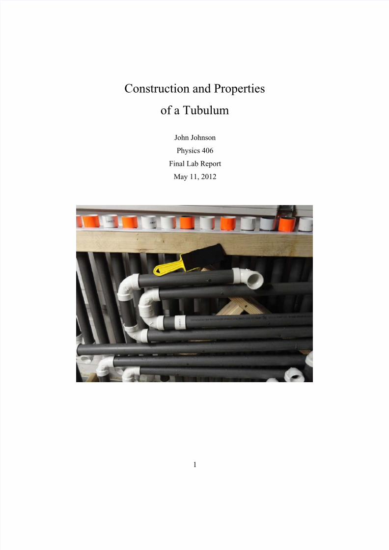
1 Construction and Properties of a Tubulum John Johnson Physics 406 Final Lab Report May 11, 2012
-
Upload
darius-high -
Category
Documents
-
view
234 -
download
1
Transcript of John Johnson P406 Project Report Sp12
7/25/2019 John Johnson P406 Project Report Sp12
http://slidepdf.com/reader/full/john-johnson-p406-project-report-sp12 1/10
1
Construction and Properties
of a Tubulum
John Johnson
Physics 406
Final Lab Report
May 11, 2012

7/25/2019 John Johnson P406 Project Report Sp12
http://slidepdf.com/reader/full/john-johnson-p406-project-report-sp12 2/10
2
Purpose
For my final project I wanted to build a musical instrument from scratch,using only well-established principals and creativity. To keep myself from
cheating by looking up directions online, I chose to build a tubulum, since Icouldn’t find any useful information on it’s construction. A tubulum was also afitting choice, given the tools required to build it, my love of strange sounds, andmy ADHD-driven affinity for drumming on things.
Theory
The tubulum is a collection of tubes of differing lengths. The pitch of eachtube is determined by its length. This makes it a form of wind instrument.However, the column of air inside the tube is vibrated by a flattened, rubbery
“beater” slapping one end of the tube, which gives it properties of a percussioninstrument. The combination of these elements result in a sharp, yet airy soundthat resonates after the initial slap of the beater.
With most percussion instruments, the beater is used to vibrate theinstrument, which in turn vibrates the air around it, creating sound. With thetubulum, however, the beater itself moves the air. When the beater hits the openend of the tube, it bounces back, which sends a pocket of high-pressure air intothe tube. The pocket of air resonates in the tube at a frequency determined by itslength and the width of the openings. Therefore the tubulum can be thought of asseries of Helmholtz resonators.
Since each tube serves only as a resonator, it’s best to use materials thatdampen vibrations caused from being struck directly while reflecting soundwaves from an external source. PVC piping works well. A wide rubber hosewould be ideal if the inner wall didn’t absorb the sound waves. The beater needsto have a flat, rubbery surface with which to strike the end of the tube. It needs tobe soft enough to not vibrate the pipe upon impact, yet heavy enough to move airquickly.
The length (L) of each tube is determined by the desired frequency (F),the velocity (V) of sound in air, and an end correction factor (C) in the followingformula: [L = V/(2F) – C], where C=0.33x(diameter).
Measurements
To test the validity of the equation relating pipe length to frequency, I useda chromatic tuner to measure the resonant frequencies of differing lengths oftubes. The tuner displays which even temperament note the frequency is closestto, along with the number of cents above or below it. Using the logarithmic

7/25/2019 John Johnson P406 Project Report Sp12
http://slidepdf.com/reader/full/john-johnson-p406-project-report-sp12 3/10
3
equations for the even temperament scale and a list of note frequencies, Icalculated the frequencies of sample lengths of pipe ranging from .43 meters to3.36 meters.
All measurements were taken on straight lengths of 1.5 inch diameterPVC conduit with straight fittings on both ends. The larger diameter fittings
served to botch standardize poorly-cut pipe ends and catch more air whenplayed, thereby creating a louder sound.
The velocity of sound in air had to be calculated because I had no way tomeasure it directly. The speed of sound is dependant on temperature, humidity,and pressure. I used usairnet.com to get local air pressure readings. I used aportable, digital thermometer/humidity meter for the other two variables. Icalculated the speed of sound to vary between 344m/s to 348m/s for the range ofconditions that would be reasonable to expect indoors. Therefore it was crucial tohave an accurate measurement of V.
The results are charted below. As predicted, the difference between the
measured wavelength and the measured tube length varied by an amount thatstayed constant, rather than varying with length. The rms of the differences was1.56cm. Given the diameter of 4.8cm, the measured end correction constant was(.325)D, which is very close to the predicted value of 0.3.
Tube Length Frequency Wavelength Note Difference Variables
0.45 374.29 0.464 F3#+20 0.0138 25 celcius
0.74 229.74 0.756 A3#-25 0.0157 55% hum.
1.16 148.54 1.169 D+20 0.0138 101.2 kPa
1.57 109.68 1.583 A2-10 0.0178 347.22m/s
1.85 93.03 1.866 F2#+5 0.0161 D=0.048m
3.07 56.32 3.083 A1+41c 0.0127 RMS=.0156
3.36 51.47 3.373 G1#-15c 0.0184 C=(.325)D
It is important to note that during my initial measurements, I found thedifference between the two measurements to vary as a function of length. I didnot realize, however, that the ambient temperature was changing as I was takingmy measurements. This change correlated to the length of pipes I wasmeasuring, which initially led to false conclusions. It also led to much re-adjustingas I built the actual tubulum.
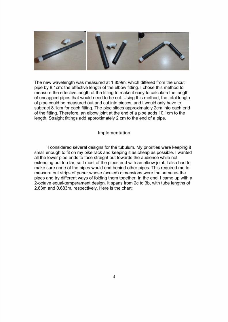
Since many of the pipes had to be quite long, 90 degree elbow fittingswould be required in the design of the tubulum if I ever wished to get it out of mygarage. Therefore, I had to measure what effective wavelength an elbow fittingadded to a pipe. I measured the wavelength of a 1.84m pipe to be 1.93m. I thencut the pipe in half and attached the two pieces together using the elbow fitting,as shown below:
7/25/2019 John Johnson P406 Project Report Sp12
http://slidepdf.com/reader/full/john-johnson-p406-project-report-sp12 4/10
4
The new wavelength was measured at 1.859m, which differed from the uncutpipe by 8.1cm: the effective length of the elbow fitting. I chose this method tomeasure the effective length of the fitting to make it easy to calculate the lengthof uncapped pipes that would need to be cut. Using this method, the total lengthof pipe could be measured out and cut into pieces, and I would only have tosubtract 8.1cm for each fitting. The pipe slides approximately 2cm into each end
of the fitting. Therefore, an elbow joint at the end of a pipe adds 10.1cm to thelength. Straight fittings add approximately 2 cm to the end of a pipe.
Implementation
I considered several designs for the tubulum. My priorities were keeping itsmall enough to fit on my bike rack and keeping it as cheap as possible. I wantedall the lower pipe ends to face straight out towards the audience while notextending out too far, so I most of the pipes end with an elbow joint. I also had to
make sure none of the pipes would end behind other pipes. This required me tomeasure out strips of paper whose (scaled) dimensions were the same as thepipes and try different ways of folding them together. In the end, I came up with a2-octave equal-temperament design. It spans from 2c to 3b, with tube lengths of2.63m and 0.683m, respectively. Here is the chart:

7/25/2019 John Johnson P406 Project Report Sp12
http://slidepdf.com/reader/full/john-johnson-p406-project-report-sp12 5/10
5
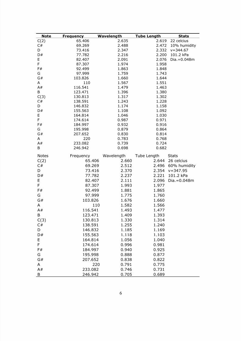
It was 24 degrees celcius and 50% humidity when I was building/tuningthis thing. If you’re going to build one, I can not emphasize enough how importantit is to keep your environment stable when fine tuning a tubulum. As shown in the
charts below, one with warmer, humid air and the other with cooler, dry air, thelowest “key” changes by 2.4cm. This is quite noticeable, considering the range ofconditions is easily what you’d expect in any Loomis classroom.
Note Frequency Wavelength Tube Length Stats
C(2) 65.406 2.649 2.633 24 celcius
C# 69.269 2.501 2.486 50% humidity
D 73.416 2.360 2.344 v=346.5
D# 77.782 2.227 2.212 101.2 kPa
E 82.407 2.102 2.087 Dia.=0.048m
F 87.307 1.984 1.969
F# 92.499 1.873 1.857
G 97.999 1.768 1.752
G# 103.826 1.669 1.653
A 110 1.575 1.559
A# 116.541 1.487 1.471
B 123.471 1.403 1.388
C(3) 130.813 1.324 1.309
C# 138.591 1.250 1.234
D 146.832 1.180 1.164
D# 155.563 1.114 1.098
E 164.814 1.051 1.036
F 174.614 0.992 0.977
F# 184.997 0.937 0.921
G 195.998 0.884 0.868
G# 207.652 0.834 0.819
A 220 0.788 0.772
A# 233.082 0.743 0.728
B 246.942 0.702 0.686
7/25/2019 John Johnson P406 Project Report Sp12
http://slidepdf.com/reader/full/john-johnson-p406-project-report-sp12 6/10
6
Note Frequency Wavelength Tube Length Stats
C(2) 65.406 2.635 2.619 22 celcius
C# 69.269 2.488 2.472 10% humidity
D 73.416 2.347 2.332 v=344.67
D# 77.782 2.216 2.200 101.2 kPa
E 82.407 2.091 2.076 Dia.=0.048mF 87.307 1.974 1.958
F# 92.499 1.863 1.848
G 97.999 1.759 1.743
G# 103.826 1.660 1.644
A 110 1.567 1.551
A# 116.541 1.479 1.463
B 123.471 1.396 1.380
C(3) 130.813 1.317 1.302
C# 138.591 1.243 1.228
D 146.832 1.174 1.158
D# 155.563 1.108 1.092
E 164.814 1.046 1.030
F 174.614 0.987 0.971F# 184.997 0.932 0.916
G 195.998 0.879 0.864
G# 207.652 0.830 0.814
A 220 0.783 0.768
A# 233.082 0.739 0.724
B 246.942 0.698 0.682
Notes Frequency Wavelength Tube Length Stats
C(2) 65.406 2.660 2.644 26 celcius
C# 69.269 2.512 2.496 60% humidity
D 73.416 2.370 2.354 v=347.95
D# 77.782 2.237 2.221 101.2 kPa
E 82.407 2.111 2.096 Dia.=0.048mF 87.307 1.993 1.977
F# 92.499 1.881 1.865
G 97.999 1.775 1.760
G# 103.826 1.676 1.660
A 110 1.582 1.566
A# 116.541 1.493 1.477
B 123.471 1.409 1.393
C(3) 130.813 1.330 1.314
C# 138.591 1.255 1.240
D 146.832 1.185 1.169
D# 155.563 1.118 1.103
E 164.814 1.056 1.040F 174.614 0.996 0.981
F# 184.997 0.940 0.925
G 195.998 0.888 0.872
G# 207.652 0.838 0.822
A 220 0.791 0.775
A# 233.082 0.746 0.731
B 246.942 0.705 0.689
7/25/2019 John Johnson P406 Project Report Sp12
http://slidepdf.com/reader/full/john-johnson-p406-project-report-sp12 7/10
7
Results
I was able to complete the tubulum, albeit with a bit more trial and error
than I had expected. The project reminded me that no matter how good yourmeasurements are, things will always need adjusting when applied in the realworld. When I completed the chart on page 5, I went to the garage to measurethe longest and shortest pipes on my project. To my surprise, the shortest waswithin 1cm of the predicted value, and the longest pipe was within 2cm! –Barelyenough to notice a difference in pitch.
There was no way to measurably predict what design for the paddles(beaters) would be best. I tried using foam from gym floor squares, but it was toolight to deliver enough force to the pipe opening. I ended up using plastic paintscrapers for handles, with felt furniture pads glued onto them. The felt pads werestiff enough to form a solid air seal when smacked against the pipe ends. To givethem more weigh and the right texture, I cut a mouse pad in half and wrapped itover the felt, with the rubbery side facing out. I used hot glue to hold everythingtogether. It works pretty well! It’s in the picture on the title page.
Altogether, materials totaled about $150. I easily spent five full daysworking on this, two of which were spent measuring and planning. My hope isthat anyone interested in building a tubulum could save themselves two days byreading this report.
Conclusion
After my presentation in class, I wrapped the “black keys” in orange ducttape to distinguish them from the other notes. So far I’ve learned to play theBatman theme song and the beginning of “Like a Virgin” by Madonna. It’s beennice to use my knowledge of physics to actually build something. Many aspectsof music seemed arbitrary before I took this class, but after working with theequations and tuning an instrument for the first time, it makes perfect sense now.I look forward to wasting many hours learning how to play Nintendo theme songson my new creation. The finished product is below:
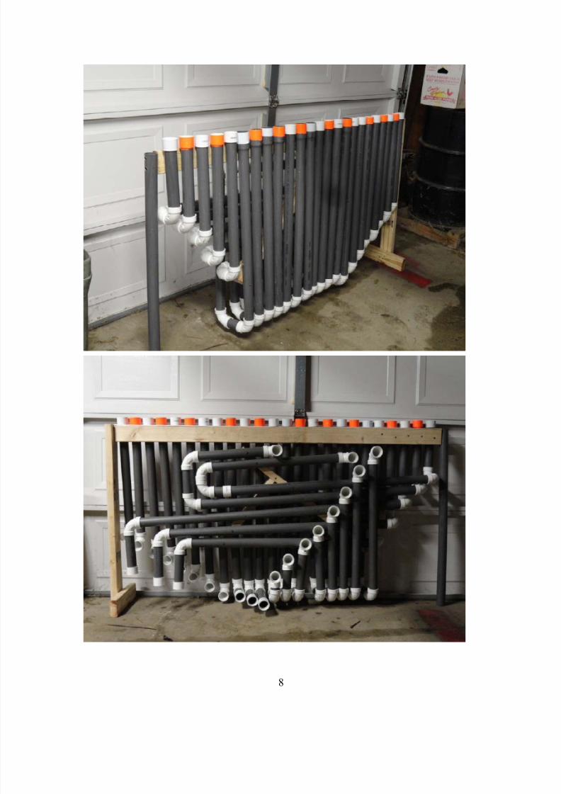
7/25/2019 John Johnson P406 Project Report Sp12
http://slidepdf.com/reader/full/john-johnson-p406-project-report-sp12 8/10
8
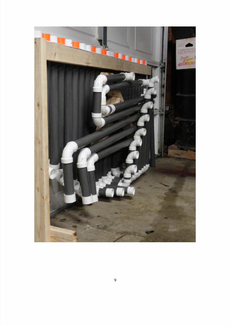
7/25/2019 John Johnson P406 Project Report Sp12
http://slidepdf.com/reader/full/john-johnson-p406-project-report-sp12 9/10
9

7/25/2019 John Johnson P406 Project Report Sp12
http://slidepdf.com/reader/full/john-johnson-p406-project-report-sp12 10/10
10


![Petroleum ASTM D1250-04 SP12[1]](https://static.fdocuments.us/doc/165x107/54658f3cb4af9f3f3f8b4fe8/petroleum-astm-d1250-04-sp121.jpg)