
Romain Guignard, Jean-Louis Wilquin, Jean-Baptiste Richard, François Beck
Revisiting the ULDB option – an investigation for a day-boat projectJean-François Masset – May 2021 [email protected]
Abstract
This investigation is about revisiting the ULDB option (Ultra Light Displacement Boat) for a day-boatproject. The ULDB concept at such appeared at the dawn of the 70s : long waterline, quite narrow,light displacement to plane downwind, not too canvassed for their length so as to be easy tohandle, and last but not least cheaper for the speed they could offer in those days.
We wanted to reconnect with this original approach, precisely the search for an optimum lightdesign for a given displacement and a given sail plan, and not an optimum at constant length asundertaken now for most current modern designs. An approach actually based on an economy ofmeans, i.e. the philosophy underlying the ULDB concept, that could be summed up by "faster forthe sail area, cheaper for the length", where the « ultra light » feature can be obtained usingstandard materials, scantlings and building methods, avoiding expensive « exotic » methods,products and materials.
For that purpose, we have imagined to explore the variants from an initial Loa 8,15 m day-boat,keeping unchanged :
– the displacement, including unit or fixed masses involved in the mass estimate,– the sail plan and area,– the general shape of the hull and the proportion of its front and rear overhangs, – the planform of the keel-bulb and of the rudder, the keel draft,– the minimum freeboard (15 cm) at heel 30°.
5 hull lengths by 8 hull beams were investigated, so 40 versions of the dayboat. In order to respectthe displacement, each extra length or extra beam from the initial design is made possible byreducing the keel weight, reducing so the ballast ratio : it is the main rule of the game. Theminimum freeboard rule has also an impact on the hull area and so on its mass, and consequentlyalso requiring an adjustment of the mass of the keel-ballast, in more or in less depending thecases. To mention the two extremes of the investigation, we have explored from :
Loa 8,15 m Boa 2,34 m Ballast ratio 46,2 % DLR 116 , up to :
Loa 11,75 m Boa 3,04 m Ballast ratio 22,9 % DLR 39, all versions being at light weight displacement of 1517 kg and sails area upwind 33,7 m2.
We have examined both the performance issue (with light crew 2 / 140 kg) and the stability issue(with heavy crew 5 / 375 kg, aiming for Category C approval).
Main results of this approach : The longer versions give better speeds whatever the wind force and direction, and this despite thelower ballast ratio : we have shown that the reduction of the ballast weight in order to have inexchange more length of hull can be done without loss of righting moment for the usual heels 0° to30°. For light winds Force 2 -3, the narrowest the better although the speed loss is low when the beamincreases. For winds 16 knots and over, the wider the better. For moderate winds 3-4, all beams ofthe range (from 2,34 m to 3,04 m) are roughly equivalent for the performance. The significant
difference here introduced by more beam is for the heel angle reduction, up to 4° less with the3,04 m version / the 2,34 m one.
The Froude range involved for these optimized long versions remains ≤ 0,5 for winds < 20 Knots.The speed benefit demonstrated by the VPP lies mostly in the reduction of the residuary dragwithin the displacement mode, which can overcome the increase of the friction drag. That doesnot show the other advantage usually granted for the ULDB, i.e. downwind for winds ≥ 20 Knotsthe overspeed capacity in semi-planing mode that low DLR lets you hope.
But these rewarding evolutions towards a long version with a reduced ballast ratio encountered alimit, which is not that of performance but first of all that of knock-down stability, precisely thecapacity to upright from a capsized position with the masthead at water level, according to theregulatory conditions required for Cat. C. (Angle of Vanishing Stability AVS > 90°). At an early stageof the project, it is wise to aim this goal with a safety margin, i.e. a minimum of 100° to 105° AVSwith the most defavorable loading (5P / 375 kg). This can eliminate some of the « best » solutions,e.g. the Loa 11,75 m x Boa 3,04 m x Ballast ratio 22,9 % version wich gives just 97° of AVS.Generally speaking, too large beam and/or too low ballast ratio leads to a strong reduction of theAVS, it is the real stop in the search for the most efficient version for a given displacement and sailplan, before too much wetted surface.
In conclusion, this investigation gives arguments that such « vintage » ULDB can still be aninteresting concept for having an easy, fast and fun long sailboat for its displacement and its sailsarea, and so roughly for a given budget.
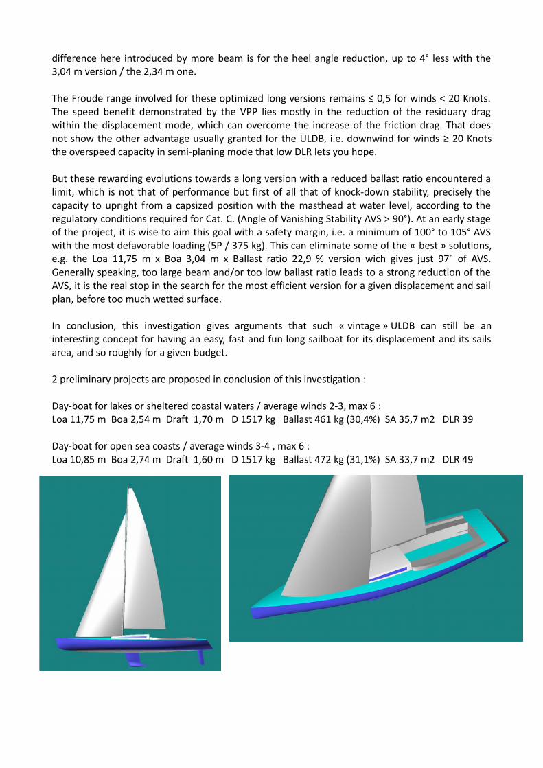
2 preliminary projects are proposed in conclusion of this investigation :
Day-boat for lakes or sheltered coastal waters / average winds 2-3, max 6 : Loa 11,75 m Boa 2,54 m Draft 1,70 m D 1517 kg Ballast 461 kg (30,4%) SA 35,7 m2 DLR 39
Day-boat for open sea coasts / average winds 3-4 , max 6 :Loa 10,85 m Boa 2,74 m Draft 1,60 m D 1517 kg Ballast 472 kg (31,1%) SA 33,7 m2 DLR 49

Summary
1. Introduction
2. The daysailer programme and the investigation principle
3. Investigation input data and conditions
4. The initial design
5. Investigation output
5.1 Evolution of some key parametersBallast ratioFreeboard at midshipPotential headroom in the central cabinRighting moment RM20° at heel angle 20°Wetted surface Sw20° at heel angle 20°Waterline beam Bwl20° at heel angle 20°
5.2 The performanceAverage speed in light winds (Force 2-3)Average speed in moderate winds (Force 3-4)Average heel upwind by Force 4Average speed with 16 Knots wind (top Force 4)Extra speed with crew 5 /375 kg on the windward rail
5.3 The stability issue Gz curve, angle of vanishing stability AVS and STIX
6. ConclusionsDiscussion on this approachDiscussion on the main resultsDay-boat early stage designs :
For lakes & sheltered coastal waters / average winds 2-3, max 6For open sea coasts / average winds 3-4, max 6

1. Introduction
This investigation is about revisiting the ULDB option (Ultra Light Displacement Boat) for a day-boatproject. The ULDB concept appeared at the dawn of the 70s, being itself an extension of the lightdisplacement sailboats that appeared earlier mostly thanks to the use of plywood. They were longby the waterline, rather narrow, light enough to plane downwind, not too canvassed for theirlength so easy to handle and last but not least cheaper for the speed they could offer in thosedays. They influenced the sailboat design as an alternative to the IOR style.
What means ULDB : by definition a low Displacement Length ratio DLR, let'say < 100 to take arounded value. Such ratio can be obtained of course through the use of light materials and ofminimalist cabin accommodation, but above all by the deliberate choice to favour the waterlinelength of the boat for a given displacement, and this without worrying about the consequence onthe IOR rating of those days. That was a kind of subversive approach within the dominant era ofthe IOR rule, to name few iconic of these mavericks : John Spencer (NZ) / Ragtime, Bill Lee (US) /Merlin and Michel Joubert (Fr) / Subversion. To be able to win prestigious races in real time withsuch light and much less expensive sailboats in front of the cream of the class 1 of those days wasa revelation.
That lead to the why :
– to privilege the waterline length has a well known direct influence for the potential speed,true for any displacement light or heavy. Usual top speed reachable for a sailboat in itsdisplacement mode, in terms of Froude number Fn, being Fn ~ 0,35 when upwind or ~ 0,45when downwind.
– to privilege the light displacement adds to that perspective the capacity to plane whendownwind, i.e. largely beyond Fn 0,45 providing the wind and the sail area are sufficient,and it is admitted that a DLR < 130 is a threshold to have occurrences of such fast sailing.
– to note that this works only if the boat is also « powerful » enough, here we refer to thenecessary righting moment thanks to both hull beam and keel ballast, it is the delicatebalance to achieve for an ULDB design : long and light but still stiff enough.
This approach usually led to long and quite narrow boat (« cigar » like) in the 70s and 80s, easilyfast thanks to less sail area to handle, also appropriated for short and singlehanded sailing, able oflong planing periods in some favorable conditions. In short, a lot of fun with a remarkableeconomy of means and budget.
But another evolution arose at the turn of the 90s when open classes with fixed hull length as N°1rule appeared aside the development of singlehanded races dedicated to monohulls, VendéeGlobe mostly. The length being fixed, the search of speed moved to the increase of power by allother means : wide boat, high draft keel-bulb, large sail areas, water ballasts, canting keel, scowbow, foils, … The ULDB underlying philosophy which was to make a fast boat with a great economyof means has become that of making the most powerful possible boat within the frame of a fixedlength. Thanks to the use of new materials and production techniques, carbon fiber, sandwhich,vacuum infusion,etc... this evolution was made possible while staying light, e.g. a 60' Imoca at 8tons is at DLR 37 ! So, they are also ULDB by definition while very different of the original ULDBsand their genuine guideline : easy and fast with a great economy of means and handling.
Current racing and most of the cruising sailboats are directly influenced by this evolution, evenwhen their DLR is > 100, because of the advantage of the volume offered for an extensive cabin
accommodation. Although it is now clear that an original ULDB can no longer claim to competewith modern beamy designs at equal length, nonetheless they can still be an interesting conceptfor an easy fast and fun sailboat at a given displacement without pre choice of the length. It is themotivation of this investigation to demonstrate the relevance of that approach for a daysailer :« Faster for the sail area , cheaper for the length ».
2. The daysailer programme and the investigation principle
A daysailer, as it is named, is dedicated to sail for the day (at max. a week-end for two persons), forthe pleasure to helm a pleasant and reactive sailboat, or just for a moment of relaxation at sea, asail alongside scenic coasts.
The design classification in cat. C , i.e. for winds up to force 6 inclusive (up to 27 Knots) and wavesup to significant heights of 2 m inclusive, is fully relevant. A cabin with a toilet and 2 to 4 benches /berths, and an headroom of 1,30 m to 1,40 m for a confortable sitting position, is the acceptableaccomodation for such programme, a head room of 1,80 m would impact too much the design. Forthe midship freeboard, the requirement is set at + 15cm when heeled at 30° angle : this constraintis important for the relevance of the iterations.
We started with a 27' daysailer design, done with « Gene-Hull Sailboat », of Loa 8,15 m, Boa 2,54m, light weight 1517 kg kept constant during the iterations, leading to a light (but not ultra-light atthis stage) DLR of 116. The investigation covers both an Loa range from 27' to 39', step 3' (8,15 mto 11,75 m, step 0,9 m) and a Boa range from 2,34 m to 3,04 m, step 0,1m , so covering a range ofDLR from 116 to 39 at constant displacement.
The sail area is also a constant within the investigation, set (when upwind) at 33,7 m2, giving anSA/D^(2/3) = 25,9 , reasonably high but not extreme by far by today standard.
Comment : that kind of search for an optimum was described by Bill Lee itself for the design of theSanta Cruz 27 :
« We worked up a preliminary design that was 25 feet long with 9 feet of beam and had all of thebumps in the IOR places. After much discussion, the customer further refined his goals.
"In this quarter ton racing, they seem to race until they find out who has the fastest boat and then the fleet falls apart. What I really want is to be first to the bar. But my budget is limited to that of the proposed quarter tonner."
We put on our thinking caps and reworked the concept. The new boat would have the same rig, same keel, same rudder, etc, but would be 27 feet long with 8 feet of beam so as to have about the same surface area and bill of materials. »
In addition to a displacement set constant (at 1517 kg), the mass units (for the hull surface, for thedeck surface) and sub-systems masses (for the rig and its features, for the cabin accommodation,for the rudder-helm system) are constants. The variables are the areas of the hull and of the deck,and the mass of the keel-bulb, in order to keep constant the displacement. Details on the inputdata regarding the masses are given in the following chapter.
The performance comparison is done with loading and righting moment corresponding to a crewof 2 / 140 kg seated to windward (at Y 1m) : we don't want to design a boat which shows its bestwith 6 to 8 crews on the windward rail, but adapted to a more usual crew of 2 , not too heavy nor

in hiking posture. Using « SA-VPP », the performances are compared using the average boat speedand heel angle, average defined by 3 wind speeds and 3 wind angles (upwind, beam reaching,downwind). Details are given here after.
The stability comparison, with in mind a classification in Cat. C, is done with a crew of 5 / 375 kg sitcentered. Using « Gene-Hull Sailboat - Stab », GZ curves, AVS and STIX are computed. Details aregiven here after.
3. Detailed input data and conditions for the investigation
Following the general objective here above, the complete conditions and design constraints are :
– Loa : from 8,15 m to 11,75 m, step 0,9 m + 2 extra lengths (Loa 12,65 m, 13,55 m)investigated with Boa 2,34 m to show the ultim evolution.
– Boa : from 2,34 m to 3,04 m, step 0,1 m
– Keel-bulb in cast iron, of draft : 1,52 m fixed
– Light weight displacement : 1517 kg fixed
>>> the keel weight (i.e. the ballast ratio) is adjusted at each version for that goal
– Sails area when upwind and beam reaching : 33,7 m2 (Main 15,8 m2 + Jib 17,9 m2) ; whendownwind twa 135° : 67,6 m2 (main 15,8 m2 + Spi 51,8 m2)
Comment : that gives an SA/D^(2/3) = 25,9 which is a fixed value throughout theinvestigation, a reasonably high but not extreme by far by today standard for a daysailer.
– Same hull shape, as shown here after within the initial design, meaning that theadimensional parameters in « Gene-Hull Sailboat » are kept constant. The hulldisplacement, when Loa and Boa vary, is mostly kept constant by adjusting the hull bodydraft. The keel line shape is itself very slightly adjusted just to also keep constant theprismatic coefficient Cp (~ 0,55) and the LCB relative position (~ 47% Lwl).
– Same overhangs proportion such as, with the loading of 140 kg (crew of 2), Lwl = 0,9 Loafor all iterations, so minimal overhangs and a Lwl close to Loa as it was also in the spirit ofthe original ULDBs.
Comment : that gives a range of DLR from 116 to 39 for the investigation
– Minimum freeboard at 30° heel angle (with light crew 140 kg) : 15 cm
Comment : that condition is important, requiring to adapt the freeboard for each version,and so impacting the hull area and consequently the hull weight and its height + the deckheight. This helps to make the comparison homogeneous.
– The mass units (for hull and deck) and the items global masses (for equipment) are set fixedand are defined as follows:
– Hull (skin, structure, keel interface) : 14 kg/m2 of average hull surface unit weight, butwith height Zg of the hull center of gravity taking into account the thicker skin in thebottom.
– Deck (skin, cockpit, roof) : 12 kg/m2 of average deck surface unit weight, a relatively
high value to take into account both the recess of the cockpit and the protuberance ofthe roof.
– Rig, sails and deck fitting : 132 kg , a fixed value as the sailplan is a constant for allversions.
– Cabin accommodation : 170 kg , a fixed value for 2 benches, a toilet and a fore doubleberth, without inboard motor, kept constant for all versions whatever the hull length orwidth.
– Keel : a variable mass of cast iron (to keep the displacement constant) within a constantplanform and draft (1,52 m)
– Rudder-Helm system : 25 kg, a fixed value.
The locations X and Z of these masses are variables coming from the Gene-Hull definition for eachversion.
4. The initial design
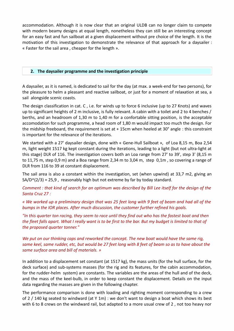
The initial design was mostly based on average values from existing 27' daysailers, for a DLR of 116which is light but not extreme. So a sailboat which can be build within conventional techniqueswithout using expensive materials like carbon fibers or carbon mast, including a minimum ofaccommodation that one can expected in a 27' daysailer. To note that the design values and hullshape have similiraties with the ones of the « Santa Cruz 45 », an « ULDB by purpose » of the 70'sby Bill Lee.
Hull :Loa : 8,15 m Boa : 2,54 m TE : 1,52 m Disp. light weight : 1517 kg Ballast 670 kg (44,2 %) Lwl 7,15 m Bwl 2,06 m Cp : 0,554 LCB 47,0 %Lw Sw 13,99 m2 DLR 116
-100 -50 0 50 100 150 200 250 300 350 400 450 500 550 600 650 700 750 800 850
-200
-150
-100
-50
0
50
100
150

-150 -100 -50 0 50 100 150
-200
-150
-100
-50
0
50
100
150
-100 0 100 200 300 400 500 600 700 800 900
-200
-100
0
100
200
-150 -100 -50 0 50 100 150
-200
-150
-100
-50
0
50
100
150
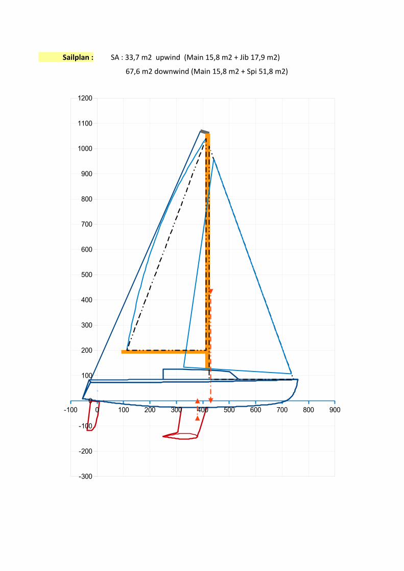
Sailplan : SA : 33,7 m2 upwind (Main 15,8 m2 + Jib 17,9 m2)
67,6 m2 downwind (Main 15,8 m2 + Spi 51,8 m2)
-100 0 100 200 300 400 500 600 700 800 900
-300
-200
-100
0
100
200
300
400
500
600
700
800
900
1000
1100
1200

Mass spreadsheet :
5. Investigation output
5.1 Evolution of some key parameters
The DLR number : within the investigation covering 5 Loa x 8 Boa with the displacement keptconstant, the DLR (the ratio of reference to judge the degree of ULDB) of course decreases with theincrease of the length. Here we give the waterline length Lwl and the DLR for the Displacementwith the loading of 2 crew/140 kg adopted for the performance comparison, i.e. with D = 1517 +140 = 1657 kg.
Displacement 1657 kg
Loa 8,15m>> Lwl 7,36 m
Loa 9,05m>> Lwl 8,16 m
Loa 9,95m>> Lwl 8,98 m
Loa 10,85 m>> Lwl 9,80 m
Loa 11,75 m>> Lwl 10,62 m
DLR 116 85 64 49 39
The longitudinal views here below gives an illustration of the investigation with length :
Loa 8,15 m Lwl 7,36 m >> DLR 116
Mass and Xg, Zg position – early stage estimation ResultsL or S or V mass unit Mass Xg M Xg Zg M Zg
m or m2 or m3 or % Disp. (kg) (m) (m)
24,41 14,00 341,70 3,28 1121,65 0,09 30,09, with S, Xs and Zs from Gene-Hull sheet (kg/m2)
14,87 12,00 178,42 3,03 539,92 0,80 142,96, with S, Xs and Zs from Gene-Hull sheet (kg/m2)
Rig, sails and deck fittings 8,70 131,95 3,85 507,42 2,72 359,05(% Disp.)
Cabin accomodation and motor 11,20 169,86 3,22 546,54 0,13 21,54(% Disp.)
Keel 669,65 3,52 2356,77 -0,98 -658,77
Rudder 0,37 1,65 25,02 -0,12 -2,99 -0,53 -13,26(% Disp.)
1516,6 3,343 5069,31 -0,078 -118,39
Hull (skin, structure, keel interface)
Deck – roof – cockpit (skin and structure)
Results : Light weight boat >>>
-150 -100 -50 0 50 100 150 200 250 300 350 400 450 500 550 600 650 700 750 800 850 900 950 1000 1050 1100 1150
-200
-150
-100
-50
0
50
100
150

Loa 9,05 m Lwl 8,16 m >> DLR 85
Loa 9,95 m Lwl 8,98 m >> DLR 64
Loa 10,85 m Lwl 9,80 m >> DLR 49
Loa 11,75 m Lwl 10,62 m >> DLR 39
-150 -100 -50 0 50 100 150 200 250 300 350 400 450 500 550 600 650 700 750 800 850 900 950 1000 1050 1100 1150
-200
-150
-100
-50
0
50
100
150
-150 -100 -50 0 50 100 150 200 250 300 350 400 450 500 550 600 650 700 750 800 850 900 950 1000 1050 1100 1150
-200
-150
-100
-50
0
50
100
150
-150 -100 -50 0 50 100 150 200 250 300 350 400 450 500 550 600 650 700 750 800 850 900 950 1000 1050 1100 1150
-200
-150
-100
-50
0
50
100
150
-150 -100 -50 0 50 100 150 200 250 300 350 400 450 500 550 600 650 700 750 800 850 900 950 1000 1050 1100 1150
-200
-150
-100
-50
0
50
100
150

The ballast ratio :
Such investigation with various Loa and Boa can be done at constant displacement only if theballast is adapted accordingly :
When we evolve to either more length (at constant beam) or more beam (at constant length), thehull and the deck areas increase and so, at constant total weight, the ballast is reduced. From leftto right, it is the evolution with Loa (from 8,15 m to 11,75 m), and from blue curve to orange curveit is the evolution with Boa (from 2,34 m to 3,04 m). The whole range of ballast ratio so decreasesfrom 46,2% (here 701 kg) when Loa = 8,15 and Boa = 2,34 m, to 22,9% (here 347 kg) when Loa =11,75 and Boa = 3,04 m. We evolve from a typical ballast ratio for the shortest & narrowest versionto a very light ballast ratio for the longest & widest one : we will see here-after the consequenceboth for the performance and to comply with the category C stability criteria.
The freeboard at midship :
This data actually varies a bit within the investigation due to the rule of maintaining 15 cm of free-board when the boat is heeled at 30° (with the crew 140 kg loading). And this changes the hullsurafce and consequently the mass of the hull body.
8 8,5 9 9,5 10 10,5 11 11,5 1220
25
30
35
40
45
50
Ballast (% light weight)
From Blue = Boa 2,34 m to Orange = Boa 3,04 m
Loa (m)
% B
alla
st
Boa (m) > 2,34 2,44 2,54 2,64 2,74 2,84 2,94 3,04Loa (m) Ballast (%)
8,15 46,2 45,2 44,1 43,1 42,0 41,0 40,0 38,99,05 43,0 41,9 40,7 39,6 38,3 37,2 36,0 34,99,95 39,9 38,6 37,2 36,0 34,7 33,4 32,2 30,910,85 36,5 35,2 33,8 32,5 31,1 29,6 28,3 26,811,75 33,4 31,9 30,4 28,9 27,4 25,9 24,4 22,9

The need of more freeboard when the beam increases was predictable. Less evident was the factthat a slightly lower freeboard is possible when we lengthen the boat at constant beam : theexplanation lies in the following about the righting moment at heeled angle.
Potential headroom in the central cabin :
This parameter is given as an indication, as it depends of the roof height which is of second orderof magnitude for its contribution to the total weight. For the investigation, the roof height abovethe deck is assumed a fixed proportion of the boat beam (here 16%), and combined with hullfreeboard and the hull body draft adjusted for each version, that gives a potential headroom. Forthe final project of the boat, it will be possible to adopt a higher roof to gain the 5-10 cm thatcould offer a more comfortable sitting (although it must be admitted that a headroom for a standup position is out of scope for such an optimized day boat).
The range of values appears to be 126 cm - 150 cm.
From left to right, the potential headroom decreases with increasing the length at constant beam,a loss of about 8 cm : it is due mostly to the decrease of the hull body draft and partly due to thelower freeboard.
From the blue curve (Boa 2,34 m) to the orange curve (Boa 3,04 m), the headroom increases, again of about 15 cm : it is due to the increase of the beam despite the decrease of the hull bodydraft.
Boa (m) > 2,34 2,44 2,54 2,64 2,74 2,84 2,94 3,04Loa (m) Free-board at midship (cm)
8,15 71,0 72,0 73,5 75,0 76,5 78,0 79,0 80,59,05 70,0 71,0 73,0 74,0 75,5 77,0 78,0 79,09,95 69,0 70,5 72,0 73,0 74,5 75,5 77,0 78,510,85 69,0 70,0 71,0 72,0 73,5 75,0 76,0 77,511,75 68,0 69,0 70,5 71,5 73,0 74,0 75,5 77,0
Boa (m) > 2,34 2,44 2,54 2,64 2,74 2,84 2,94 3,04Possible headroom in the central cabin (under the roof)
8,15 135 136 139 141 143 146 148 1509,05 132 134 137 138 141 143 145 1479,95 130 132 134 136 139 141 143 146
10,85 128 130 132 134 137 139 141 14411,75 126 128 131 133 135 137 140 142

The righting moment RM20° at heel angle 20°
What happens at the heel angle 20° can be informative because representative of usual sailingconditions, so we here below look at the evolution of both the rigthing moment, the wettedsurface and the waterline beam. At first, the available righting moment which is the majorparameter to evaluate the « power », i.e. the capacity to sustain the aerodynamic heeling momentand so to transfer thrust to the boat.
At first, RM20° evolution at constant beam Boa :From left (Loa 8,15 m) to right (Loa 11,75 m), one can see that there is quasi no change of the RMat constant Boa and displacement, and this despite the reduction of the ballast ratio (see theballast ratio table). It seems surprising because at same beam, displacement and with a lowerballast ratio, we should expected to have a lower RM :>>> what happens is that the lateral displacement of the heeled hull center of buoyancy is morepronounced for a longer version, and that effect compensates the ballast ratio reduction : theresulting Gz number does not change. Why ? The explanation lies on the hull shape evolution :when the length increases at constant displacement and beam, the hull is then more "sitting" onthe water with a more pronounced rounded bilge, moreover accentuated by a lower freeboard(consequence of the rule of 15 cm free-board at 30° of heel), while having a smaller waterlinewidth. So when heeling, the center of volume shifts more laterally and provides more rightingmoment.
8 8,5 9 9,5 10 10,5 11 11,5 126,00
7,00
8,00
9,00
10,00
11,00
12,00
Righting Moment RM20° (at 20° heel angle)
From Blue = Boa 2,34 m to Orange = Boa 3,04 m
Boa (m)
RM
20°
(kN
.m)
Boa (m) > 2,34 2,44 2,54 2,64 2,74 2,84 2,94 3,04RM20° (kN.m)
8,15 7,26 7,69 8,11 8,53 8,97 9,43 9,93 10,419,05 7,25 7,69 8,08 8,53 8,97 9,42 9,88 10,369,95 7,25 7,67 8,07 8,55 9,01 9,52 10,00 10,5010,85 7,18 7,64 8,12 8,62 9,09 9,57 10,09 10,5811,75 7,25 7,72 8,16 8,66 9,14 9,66 10,17 10,67

Example at constant Boa 2,74 m for short Loa 8,15 m and long Loa 11,75 m :
Boa 2,74 m, Loa 8,15 m, Ballast ratio 42,0 % > Boa 2,74 m, Loa 11,75 m, Ballast ratio 27,4 %
Yhull = -0,486 m and Yweight = 0,066 m>>> Gz = 0,552 m & RM = 8,972 kN.m
Yhull = -0,566 m and Yweight = -0,003 m>>> Gz = 0,562 m & RM = 9,143 kN.m
The center of buoyancy (blue arrow) shifts from 0,486 to 0,566 m (= 80 mm) and it is sufficient tocompensate (and here even a bit more) the shift of the weight (brown arrow) from 0,066 to -0,003m (=69 mm) due to the ballast reduction. >>> Gz = 0,552 m becomes Gz = 0,562 m
-200 -150 -100 -50 0 50 100 150 200
-200
-150
-100
-50
0
50
100
150
-200 -150 -100 -50 0 50 100 150 200
-200
-150
-100
-50
0
50
100
150
-200 -150 -100 -50 0 50 100 150
-150
-100
-50
0
50
100
150
200
-200 -150 -100 -50 0 50 100 150
-150
-100
-50
0
50
100
150
200

Same shifts but shown in the bottom views :
Loa 8,15 m and Boa 2,74 m >> Yhull at 20° = -0,486 m
Loa 11,75 m and Boa 2,74 m >> Yhull at 20° = -0,566 m
So, at constant beam overall Boa and displacement D, the reduction of the ballast weight in orderto have in exchange more length of hull can be done without loss of righting moment for the usualheels around 20°.
Secondly, RM20° evolution at constant Loa :
Back to the RM curves : from blue curve (Boa 2,34 m) to orange curve (Boa 3,04 m), it is a quasilinear increase of the RM with Boa, of + 43% to + 47%. Here it is more easy to understand, morebeam means more lateral shift of the center of buoyancy and that largely overcompensates thelower ballast ratio.
-100 0 100 200 300 400 500 600 700 800 900 1000 1100
-200
-100
0
100
200
-100 0 100 200 300 400 500 600 700 800 900 1000 1100
-200
-100
0
100
200

Example at constant Loa 9,95 m , with Boa 2,34 m and 3,04 m :
Loa 9,95 m Boa 2,34 m Ballast ratio 39,9 % >>>>> Gz = 0,446 m & RM20° = 7,255 kN.m
Loa 9,95 m Boa 3,04 m Ballast ratio 30,9 %>>> Gz = 0,645 m & RM20° = 10,498 kN.m
Loa 9,95 m Boa 2,34 m >> Yhull at 20° heel = -0,388 m
Loa 9,95 m Boa 3,04 m >> Yhull at 20° heel = -0,641 m
-200 -150 -100 -50 0 50 100 150
-150
-100
-50
0
50
100
150
200
-200 -150 -100 -50 0 50 100 150
-150
-100
-50
0
50
100
150
200
-100 0 100 200 300 400 500 600 700 800 900
-200
-100
0
100
200
-100 0 100 200 300 400 500 600 700 800 900
-200
-100
0
100
200

The wetted surface Sw20° at heel angle 20° :
Another parameter of first interest to observe is the wetted surface at such 20° heel angle (totalwetted surface, including the rudder one and the keel one which are fixed for all versions), as it isthe most evident counterpart of the advantage of longer and/or beamier versions :
From left to right, at constant beam and at 20° heel angle, the wetted surface increases with Loa :it is the main trend, + 17 % from Loa 8,15 m to Loa 11,75 m, but low when compared with Loaincrease itself 11,75/8,15 = + 44%. From the blue curve (Boa 2,34 m) to the orange curve (Boa 3,04m), the increase of hull beam at constant Loa leads to a quite low incease of the wetted surface at20° heel, just + 4% : it is the heel angle 20° that actually mitigates a lot the increase of the wettedsurface usually linked with such extra beam.
For example, for Loa = 9,95 m :
– at heel 0° : Sw0° 15,01 m2 with Boa 2,34 m >> 16,68 m2 with Boa 3,04 m (+ 11,1%)– at heel 20° : Sw20° 14,20 m2 >> 14,84 m2 (+ 4,5%)
>>> an extra +11,1% of wetted surface when upright becomes just +4,5 % when heeled at 20°
8 8,5 9 9,5 10 10,5 11 11,5 1212
13
14
15
16
17
Wetted surface Sw20° (at 20° heel angle)
From Blue = Boa 2,34 m to Orange = Boa 3,04 m
Loa (m)
Sw
20°
(m2)
Boa (m) > 2,34 2,44 2,54 2,64 2,74 2,84 2,94 3,04Sw20° (m2)
8,15 13,14 13,18 13,29 13,39 13,46 13,52 13,62 13,679,05 13,70 13,75 13,83 13,95 14,00 14,03 14,09 14,149,95 14,20 14,30 14,39 14,50 14,54 14,65 14,74 14,8410,85 14,74 14,87 14,97 15,07 15,19 15,27 15,36 15,4311,75 15,35 15,48 15,57 15,68 15,80 15,87 15,93 15,99

The waterline beam Bwl20° at heel angle 20° :
The waterline beam at 20° heel is also worth to observe with regard the expected performance,because a lower Bwl favors a lower residuary drag :
From left to right, although we are at constant Boa, the waterline beam at 20° decreases withlength of about - 9 %, it is because we are also at constant displacement.
Example :
Loa 8,15 m and Boa 2,74 m >> Bwl20° = 1,81 m
Boa (m) > 2,34 2,44 2,54 2,64 2,74 2,84 2,94 3,04Loa (m) Waterline beam Bwl20° at 20° heel angle
8,15 1,68 1,72 1,75 1,78 1,81 1,84 1,87 1,909,05 1,64 1,67 1,70 1,73 1,76 1,79 1,82 1,859,95 1,60 1,63 1,66 1,69 1,72 1,75 1,78 1,8110,85 1,57 1,60 1,62 1,65 1,68 1,71 1,74 1,7711,75 1,53 1,56 1,59 1,62 1,65 1,68 1,71 1,74
8 8,5 9 9,5 10 10,5 11 11,5 121,4
1,5
1,6
1,7
1,8
1,9
2
Beam waterline Bwl20° (at 20° heel angle)
From Blue = Boa 2,34 m to Orange = Boa 3,04 m
Loa (m)
Bw
l20°
(m
2)
-100 0 100 200 300 400 500 600 700 800 900 1000 1100
-200
-100
0
100
200
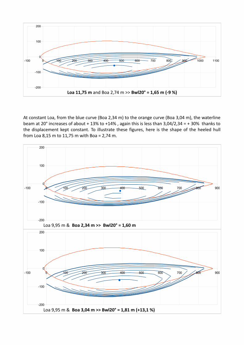
Loa 11,75 m and Boa 2,74 m >> Bwl20° = 1,65 m (-9 %)
At constant Loa, from the blue curve (Boa 2,34 m) to the orange curve (Boa 3,04 m), the waterlinebeam at 20° increases of about + 13% to +14% , again this is less than 3,04/2,34 = + 30% thanks tothe displacement kept constant. To illustrate these figures, here is the shape of the heeled hullfrom Loa 8,15 m to 11,75 m with Boa = 2,74 m.
Loa 9,95 m & Boa 2,34 m >> Bwl20° = 1,60 m
Loa 9,95 m & Boa 3,04 m >> Bwl20° = 1,81 m (+13,1 %)
-100 0 100 200 300 400 500 600 700 800 900
-200
-100
0
100
200
-100 0 100 200 300 400 500 600 700 800 900
-200
-100
0
100
200
-100 0 100 200 300 400 500 600 700 800 900 1000 1100
-200
-100
0
100
200

5.2 Performance comparison
We have seen the evolution of some key parameters with length and/or beam at constantdisplacement, as they are involved in the performance. Some are a priori favorable, when we getmore righting moment and less waterline beam at heeled angle, some at contrary can be adisadvantage, when we get more wetted surface. Only a VPP, with these parameters evolution asinput data among others, can deal with all pro's and con's effects and inform on the performanceof each versions. Here we have used SA-VPP and a comparison criterion based on an averagespeed representative of an all around performance :
The average speed is based on 3 set of wind speeds and 3 sailing angles :
Sailing angles :– upwind (at optimal twa) with Main 15,8 m2 + Fore triangle 14,8 m2
, and counted with coefficient 2– beam reaching (at 90° twa) with Main 15,8 m2 + Fore triangle 14,8 m2
, and counted with coefficient 1– downwind with spi (at 135° twa) with Main 15,8 m2 + Spi 51,8 m2
, and counted with coefficient 1
The upwind sails area introduced in the VPP (Main + Fore triangle) can be considered as equivalentto the real area SA 33,7 m2 with a mainsail 15,8 m2 + a jib 17,9 m2. Wind speeds :
– Average speed by light winds (Force 2-3) : wind 4, 7, 10 Knots– Average speed by moderated winds (Force 3-4) : wind 7, 11, 15 Knots– Wind speed 16 Knots (top Force 4)
We also look at the average heel, we consider only the upwind conditions by wind 11, 13 and 15knots (Force 4), representative of the sailboat stiffness when sailing with its full sails area (i.e.before reefing). Last but not least for this performance issue, the boat is assumed loaded with a light crew of 2 P /140 kg, sitting windward in the cockpit à Y = 1m, so the promenade conditions. For some cases, wewill also show the performance with 5P / 375 kg on the windward rail, i.e. a more racingconfiguration.
Average speed by light winds (Force 2-3)
For Boa 2,34 m, we extend the computation to very lengthy versions Loa 12,65 m and Loa 13,55 m
Boa (m) > 2,34 2,44 2,54 2,64 2,74 2,84 2,94 3,04Loa (m) Average speed by light winds Force 2-3 (4, 7, 10 Knots)
8,15 4,66 4,65 4,64 4,62 4,61 4,60 4,58 4,559,05 4,76 4,76 4,74 4,73 4,72 4,71 4,69 4,689,95 4,83 4,82 4,81 4,81 4,79 4,77 4,75 4,7310,85 4,87 4,86 4,85 4,84 4,82 4,80 4,78 4,7611,75 4,91 4,90 4,88 4,86 4,84 4,82 4,80 4,7812,65 4,9413,55 4,96
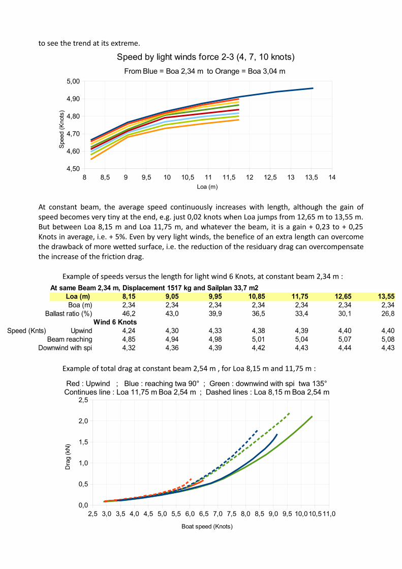
to see the trend at its extreme.
At constant beam, the average speed continuously increases with length, although the gain ofspeed becomes very tiny at the end, e.g. just 0,02 knots when Loa jumps from 12,65 m to 13,55 m.But between Loa 8,15 m and Loa 11,75 m, and whatever the beam, it is a gain + 0,23 to + 0,25Knots in average, i.e. + 5%. Even by very light winds, the benefice of an extra length can overcomethe drawback of more wetted surface, i.e. the reduction of the residuary drag can overcompensatethe increase of the friction drag.
Example of speeds versus the length for light wind 6 Knots, at constant beam 2,34 m :
Example of total drag at constant beam 2,54 m , for Loa 8,15 m and 11,75 m :
8 8,5 9 9,5 10 10,5 11 11,5 12 12,5 13 13,5 144,50
4,60
4,70
4,80
4,90
5,00
Speed by light winds force 2-3 (4, 7, 10 knots)
From Blue = Boa 2,34 m to Orange = Boa 3,04 m
Spe
ed (
Kno
ts)
Loa (m)
At same Beam 2,34 m, Displacement 1517 kg and Sailplan 33,7 m2 Loa (m) 8,15 9,05 9,95 10,85 11,75 12,65 13,55Boa (m) 2,34 2,34 2,34 2,34 2,34 2,34 2,34
Ballast ratio (%) 46,2 43,0 39,9 36,5 33,4 30,1 26,8Wind 6 Knots
Speed (Knts) Upwind 4,24 4,30 4,33 4,38 4,39 4,40 4,40Beam reaching 4,85 4,94 4,98 5,01 5,04 5,07 5,08
Downwind with spi 4,32 4,36 4,39 4,42 4,43 4,44 4,43
2,5 3,0 3,5 4,0 4,5 5,0 5,5 6,0 6,5 7,0 7,5 8,0 8,5 9,0 9,5 10,010,511,00,0
0,5
1,0
1,5
2,0
2,5
Red : Upwind ; Blue : reaching twa 90° ; Green : downwind with spi twa 135°Continues line : Loa 11,75 m Boa 2,54 m ; Dashed lines : Loa 8,15 m Boa 2,54 m
Boat speed (Knots)
Dra
g (k
N)
At the end, for light winds Force 2-3, the best average speed is obtained with the longest andnarrowest version (Loa 11,75 m x Boa 2,34 m). But it should be noted that to increase the beam atconstant length leads to quite low loss of speed, about 0,10 to 0,13 Knots, despite a radical beamchange from 2,34 m to 3,04 m giving more volume for the cockpit as for the cabin.
Comparison of the best version by Force 2-3 (Loa 11,75 m x Boa 2,34 m, Ballast ratio 33,4 %) withthe initial design (Loa 8,15 m x Boa 2,54 m, Ballast ratio 44,1 % ) :
Speed(Knots)
Upwind Beam reaching Downwind with spi
Wind(Knots)
Loa 8,15mBoa 2,54 mBallast 44,1 %
Loa 11,75mBoa 2,34 mBallast 33,4 %
Loa 8,15mBoa 2,54 mBallast 44,1 %
Loa 11,75mBoa 2,34 mBallast 33,4 %
Loa 8,15mBoa 2,54 mBallast 44,1 %
Loa 11,75mBoa 2,34 mBallast 33,4 %
4 2,91 2,99 3,34 3,50 2,88 2,94
7 4,72 4,94 5,40 5,70 4,91 5,11
10 5,67 5,90 6,34 7,17 6,20 6,86
>>> even with 4 Knots of wind, the longest version can be faster.
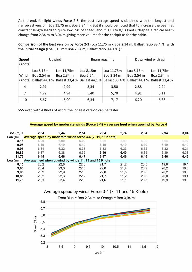
Average speed by moderate winds (Force 3-4) + average heel when upwind by Force 4
Boa (m) > 2,34 2,44 2,54 2,64 2,74 2,84 2,94 3,04Loa (m) Average speed by moderate winds force 3-4 (7, 11, 15 Knots)
8,15 6,00 6,00 6,00 5,99 5,99 5,99 5,98 5,979,05 6,19 6,19 6,19 6,19 6,19 6,19 6,19 6,199,95 6,31 6,32 6,33 6,33 6,33 6,32 6,32 6,31
10,85 6,37 6,38 6,39 6,40 6,40 6,39 6,39 6,3811,75 6,45 6,46 6,47 6,47 6,46 6,46 6,46 6,45
Loa (m) Average heel when upwind by winds 11, 13 and 15 Knots8,15 23,2 22,8 22,3 21,7 21,2 20,5 19,8 19,19,05 23,4 23,0 22,5 22,0 21,4 20,9 20,2 19,69,95 23,2 22,9 22,5 22,0 21,5 20,8 20,2 19,5
10,85 23,2 22,6 22,2 21,7 21,2 20,6 20,0 19,411,75 23,1 22,4 22,0 21,6 21,1 20,5 19,9 19,3
8 8,5 9 9,5 10 10,5 11 11,5 125,2
5,3
5,4
5,5
5,6
5,7
5,8
Average speed by winds Force 3-4 (7, 11 and 15 Knots)
From Blue = Boa 2,34 m to Orange = Boa 3,04 m
Loa (m)
Spe
ed (
Nds
)

At constant beam, from Loa 8,15 m to 11,75 m, the average speed by force 3-4 increases withlength of about + 8%, to compare with the square root of the length ratio (11,75/8,15)^0,5 = + 20%>> meaning that this extra speed is gained thanks to the extra length but at a lower Froude. On theother hand, the heel angle is similar, it is the consequence of a similar rigthing moment RM asalready explained here above for RM20°.
Illustration of the speeds versus the length, at constant Beam 2,64 m and for wind 8 and 14 Knots :
On the other hand, at same length, the speed hardly seems affected by the various beam & ballastratio solutions. For example, with length 11,75 m, the same average speed 6,45 Knots is obtainedboth with Boa 2,34 m & ballast ratio 33,4% and also with Boa 3,04 m & ballast ratio 22,9%, whilethe maximum is for Boa 2,54 m and 2,64 m with 6,47 knots, just 0,02 knots better. On the otherhand, more beam acts on the average heel, from 23,1° with Boa 2,34 m to 19,3° with Boa 3,04 m.So at constant length, a lower heel in average can be obtained with a wider hull and less ballastratio, although without a significant influence on the average speed.
Comparison of the best version by Force 3-4 (Loa 11,75 m x Boa 2,64 m, Ballast ratio 28,9 %) withthe initial design (Loa 8,15 m x Boa 2,54 m, Ballast ratio : 44,1 % ) :
Speed(Knots)
Upwind Beam reaching Downwind with spi
Wind(Knots)
Loa 8,15mBoa 2,54 mBallast 44,1 %
Loa 11,75mBoa 2,64 mBallast 28,9 %
Loa 8,15mBoa 2,54 mBallast 44,1 %
Loa 11,75mBoa 2,64 mBallast 28,9 %
Loa 8,15mBoa 2,54 mBallast 44,1 %
Loa 11,75mBoa 2,64 mBallast 28,9 %
7 4,72 4,89 5,40 5,58 4,91 5,03
11 5,82 6,18 6,61 7,42 6,52 7,18
15 6,01 6,52 7,40 8,51 7,87 8,72
The Froude range used for this optimum is mostly ≤ 0,5 within wind < 20 Knots. The speed benefitshows by the VPP lies mostly in the reduction of the residuary drag within the displacement mode,the VPP does not compute possible overspeed occurrences in the semi-planning zone over Froude0,5 and wind ≥ 20 Knots that lets you hope the low DLR =39 for this version.
At same Beam 2,64 m, Displacement 1517 kg and Sailplan 33,7 m2 Loa (m) 8,15 9,05 9,95 10,85 11,75Boa (m) 2,64 2,64 2,64 2,64 2,64
Ballast ratio (%) 43,1 39,6 36,0 32,5 29,9Wind 8 Knots Progession %
Speed (Knts) Upwind 5,13 5,23 5,30 5,31 5,35 4,3Beam reaching 5,80 6,01 6,12 6,10 6,16 6,2
Downwind with spi 5,46 5,58 5,62 5,61 5,64 3,3Wind 14 Knots
Speed (Knts) Upwind 6,00 6,21 6,38 6,41 6,47 7,8Beam reaching 7,37 7,71 7,96 8,14 8,27 12,2
Downwind with spi 7,53 7,85 8,07 8,23 8,34 10,7

Average speed by wind 16 Knots (top Force 4) :
To complement the performance comparison, this table represents the average speed by wind 16Knots which is the top of the Force 4 : for the given sail area, it is roughly the limit before a reefing for all versions.
One can see that now the best version moves towards not only the longest but also the widest,and this despite the very low ballast ratio of this version : Loa 11,75 m Boa 3,04 m Ballast ratio22,9%.
Comparison of the the best version with wind 16 Knots (Loa 11,75 m x Boa 3,04 m, Ballast ratio22,9 %) with the initial design (Loa 8,15 m x Boa 2,54 m, Ballast ratio : 44,1 % ) :
Speed(Knots)
Upwind Beam reaching Downwind with spi
Wind(Knots)
Loa 8,15mBoa 2,54 mBallast 44,1 %
Loa 11,75mBoa 3,04 mBallast 22,9 %
Loa 8,15mBoa 2,54 mBallast 44,1 %
Loa 11,75mBoa 3,04 mBallast 22,9 %
Loa 8,15mBoa 2,54 mBallast 44,1 %
Loa 11,75mBoa 3,04 mBallast 22,9 %
16 6,03 6,74 7,80 8,79 8,23 9,02
In the conditions of the comparison, at same displacement and sail area :– the optimum moves from the narrowest to the beamiest when the wind increases from
Force 2-3 to top Force 4 and over, – it is always better to exchange keel weight into extra length or beam,
The extra speed with crew 5 /375 kg on the windward rail
A comparison of the performance with crew 2 / 140 kg sit at Y = 1 m and with crew 5 / 375 kg sit atY = 1,25 m is done with the « force3-4 version » , i.e. Loa 11,75m Boa 2,64 m Ballast 28,9 % :
Speed(Knots)
Upwind Beam reaching Downwind with spi
Wind(Knots)
Crew2 140 kgat Y 1 m
Crew5 375 kgat Y 1,25 m
Crew2 140 kgat Y 1 m
Crew5 375 kgat Y 1,25 m
Crew2 140 kgat Y 1 m
Crew5 375 kgat Y 1,25 m
7 4,89 4,88 5,58 5,54 5,03 4,99
11 6,18 6,54 7,42 7,45 7,18 7,17
15 6,52 7,01 8,51 8,81 8,72 8,73
20 6,69(reefing 0,9)
7,05 9,23 9,99 10,38 10,84
Boa (m) > 2,34 2,44 2,54 2,64 2,74 2,84 2,94 3,04Loa (m) Average speed by wind 16 Knots (top Force 4)
8,15 6,97 7,00 7,02 7,03 7,05 7,06 7,08 7,099,05 7,24 7,29 7,31 7,33 7,35 7,37 7,38 7,409,95 7,42 7,48 7,52 7,55 7,57 7,59 7,60 7,6110,85 7,46 7,55 7,62 7,65 7,68 7,70 7,73 7,7511,75 7,55 7,64 7,70 7,73 7,75 7,78 7,81 7,82

>>> one can see that the performance can be significantly improved upwind (from 10 knots ofwind) and beam reaching (from 15 Knots of wind) with 5 crew on the windward line, takingadvantage of the waterline length.
About the performance limitation
From the speed curves and trends shown above, we have noticed that the maximum is not exactlyreached, and that continuing increasing the length under the set rules of constant displacementand sail area still improves the speed potential, although less and less, by a tiny margin at the end.But this trend leads also to continuously lower the ballast ratio to values < 30 to 25 % which canbecome critical for the stability criterion, it is the next issue to investigate.
5.3 The stability issue
The speed evolution shown here above are attractive but there is a limit in the decrease of the keelweight : at constant displacement, the effect is a higher position of the sailboat center of gravity,and consequently a lower capacity to self upright from a say 90° knock down occurrence. Withoutthis self upright need, we would fall at the end into a dinghy like or quasi design which has theserious disadvantage to easily capsize, and for that size of day boat it is of course impossible for thecrew to upright the boat themselves as they could easily do with a small light dinghy. So to setfrontiers between the various designs and types of use, the rule makers have defined 4 categorieswith for each stability criterias to fulfill. That mostly includes thresholds for the angle of vanishingstability AVS and for the STIX number, which both suppose to firstly compute the Gz curve with themost defavorable loading. For our investigation, we have set the objective to classify the dayboatin the category C for 5 persons on board, i.e. 375 kg of loading.
The Gz curve, the angle of vanishing stability AVS and the STIX
According to the ISO rule, the loading of reference considered (5 persons / 375 kg) is centered (Y=0) and at Z = midship free-board, and for a classification in category C in such conditions, the AVSshould be ≥ 90° and the STIX number > 14.
Remind of the thresholds (ref. ISO 12217-2 2013), with weight m = 1517 kg + 375 kg = 1892 kg
Cat. A AVS = (130 – 0,002 m) but always ≥ 100°>>> 126,2°
STIX > 32
Cat. B AVS = (130 – 0,005 m) but always ≥ 95°>>> 120,5°
STIX > 23
Cat. C AVS ≥ 90° STIX > 14
Cat. D AVS ≥ 75° STIX > 5
The Gz curves are computed for all the versions, here below are the ones for Loa = 8,15 m and Loa= 11,75 m, and covering the range of Boa (2,34 m to 3,04 m) :

What we notice first is that, at constant length as shown above, the higher Gz in the usual heelangle range (0°-30 °), the lower the value of the AVS.
The minimum AVS , 97,3° , is obtained for the longest and widest version, i.e. Loa 11,75m Boa 3,04m Ballast 22,9% : it is still > 90° but with a small margin.
0 10 20 30 40 50 60 70 80 90 100 110 120 130 140 150 160 170 180
-0,4-0,3-0,2-0,10,00,10,20,30,40,50,60,70,8
GZ curve - Loa 8,15 m - Load 375 kg
From Blue (Boa 2,34 m Ballast 46,2 %) to Orange (Boa 3,04 m Ballast 38,9 %)
Heel (°)
GZ
(m)
0 10 20 30 40 50 60 70 80 90 100 110 120 130 140 150 160 170 180
-0,5-0,4-0,3-0,2-0,10,00,10,20,30,40,50,60,70,8
GZ curve - Loa 11,75 m - Load 375 kg
From Blue (Boa 2,34 m Ballast 33,4 %) to Orange (Boa 3,04 m Ballast 22,9 %)
Heel (°)
GZ
(m)
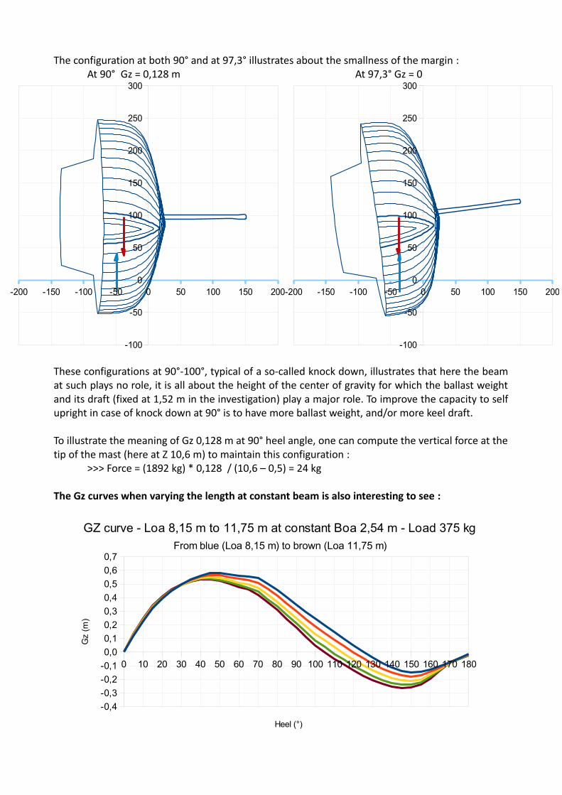
The configuration at both 90° and at 97,3° illustrates about the smallness of the margin : At 90° Gz = 0,128 m At 97,3° Gz = 0
These configurations at 90°-100°, typical of a so-called knock down, illustrates that here the beamat such plays no role, it is all about the height of the center of gravity for which the ballast weightand its draft (fixed at 1,52 m in the investigation) play a major role. To improve the capacity to selfupright in case of knock down at 90° is to have more ballast weight, and/or more keel draft.
To illustrate the meaning of Gz 0,128 m at 90° heel angle, one can compute the vertical force at thetip of the mast (here at Z 10,6 m) to maintain this configuration :
>>> Force = (1892 kg) * 0,128 / (10,6 – 0,5) = 24 kg
The Gz curves when varying the length at constant beam is also interesting to see :
-200 -150 -100 -50 0 50 100 150 200
-100
-50
0
50
100
150
200
250
300
-200 -150 -100 -50 0 50 100 150 200
-100
-50
0
50
100
150
200
250
300
0 10 20 30 40 50 60 70 80 90 100 110 120 130 140 150 160 170 180
-0,4
-0,3
-0,2
-0,1
0,0
0,1
0,2
0,3
0,4
0,5
0,6
0,7
GZ curve - Loa 8,15 m to 11,75 m at constant Boa 2,54 m - Load 375 kgFrom blue (Loa 8,15 m) to brown (Loa 11,75 m)
Heel (°)
Gz
(m)

>>> one can see that the curves are identical up to heel 30°, it is exactly what was demonstratedand explained in the RM20° section above. But for heel > 30°, and for the AVS in particular, thelower ballast ratio associated with more length leads to a reduction of the available rightingmoment in case of a capsize.
Table of the AVS and of the STIX for all the configurations :
One can see that the STIX is easily over 14 the threshold of the cat. C, and most of them are also >23 (the cat. B threshold) but it is not significant as the cabin accommodation and all equipmementthat is necessary for a Cat. B sailing are not on board. So here, STIX is not the critical issue.
On the other hand, the AVS can be close to the minimal value 90° for the cat. C , it is the criticalfigure to check, which can limit the optimization by more length and beam. Moreover, the stabilitytest for the cat. C also describe by ISO rules imply a starting configuration with the mast tip atwaterline, so an angle actually slightly over 90°, about 94,5° in our case :
This is an additionnal reason to take a margin at this early stage design phase to be sure to succeedlater on such recovery test, so it seems wise at early stage project to consider a real minimum of100° to 105° for the AVS.
Boa (m) > 2,34 2,44 2,54 2,64 2,74 2,84 2,94 3,04Loa (m) AVS (°)
8,15 132,9 128,8 125,2 122,1 119,2 116,8 114,4 112,19,05 127,0 123,1 119,7 116,3 113,5 110,7 108,1 105,79,95 121,2 117,3 113,8 111,0 108,3 105,9 104,0 102,310,85 115,4 112,1 108,9 106,5 104,2 102,3 100,8 99,611,75 111,1 107,9 104,9 102,6 100,9 99,4 98,3 97,3
Boa (m) > 2,34 2,44 2,54 2,64 2,74 2,84 2,94 3,04Loa (m) STIX
8,15 25,7 25,5 25,2 24,4 23,5 22,7 22,0 21,49,05 26,1 25,8 25,5 24,6 23,7 22,9 22,1 21,49,95 26,4 25,9 25,6 24,8 23,9 23,1 22,3 21,510,85 26,6 26,3 25,8 25,0 24,0 23,0 22,2 21,411,75 26,7 26,1 25,5 24,6 23,6 22,6 21,8 21,0
~ 94,5°

With the best performer by Force 2-3, i.e. Loa 11,75 m Boa 2,34 m Ballast 33,4 % >>> AVS 111,1°At 90° Gz = 0,202 m At AVS 111,1° Gz = 0
>>> vertical force at the tip of the mast at 90° heel : 37 kg
With the best performer by Force 3-4, i.e. Loa 11,75 m Boa 2,64 m Ballast 28,9 % >>> AVS 102,6° At 90° Gz = 0,168 m At AVS 102,6° Gz = 0
>>> vertical force at the tip of the mast at 90° heel : 31 kg
Both versions can comply with the AVS minimum for Cat. C
-150 -100 -50 0 50 100 150 200
-100
-50
0
50
100
150
200
-150 -100 -50 0 50 100 150 200
-100
-50
0
50
100
150
200
-150 -100 -50 0 50 100 150 200
-100
-50
0
50
100
150
200
250
-150 -100 -50 0 50 100 150 200
-100
-50
0
50
100
150
200
250
6. Conclusions
Discussion on this approach
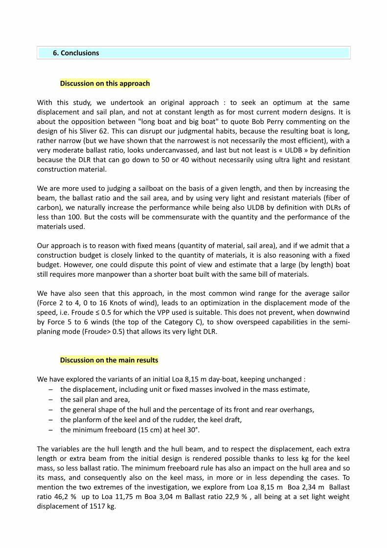
With this study, we undertook an original approach : to seek an optimum at the samedisplacement and sail plan, and not at constant length as for most current modern designs. It isabout the opposition between "long boat and big boat" to quote Bob Perry commenting on thedesign of his Sliver 62. This can disrupt our judgmental habits, because the resulting boat is long,rather narrow (but we have shown that the narrowest is not necessarily the most efficient), with avery moderate ballast ratio, looks undercanvassed, and last but not least is « ULDB » by definitionbecause the DLR that can go down to 50 or 40 without necessarily using ultra light and resistantconstruction material.
We are more used to judging a sailboat on the basis of a given length, and then by increasing thebeam, the ballast ratio and the sail area, and by using very light and resistant materials (fiber ofcarbon), we naturally increase the performance while being also ULDB by definition with DLRs ofless than 100. But the costs will be commensurate with the quantity and the performance of thematerials used.
Our approach is to reason with fixed means (quantity of material, sail area), and if we admit that aconstruction budget is closely linked to the quantity of materials, it is also reasoning with a fixedbudget. However, one could dispute this point of view and estimate that a large (by length) boatstill requires more manpower than a shorter boat built with the same bill of materials.
We have also seen that this approach, in the most common wind range for the average sailor(Force 2 to 4, 0 to 16 Knots of wind), leads to an optimization in the displacement mode of thespeed, i.e. Froude ≤ 0.5 for which the VPP used is suitable. This does not prevent, when downwindby Force 5 to 6 winds (the top of the Category C), to show overspeed capabilities in the semi-planing mode (Froude> 0.5) that allows its very light DLR.
Discussion on the main results
We have explored the variants of an initial Loa 8,15 m day-boat, keeping unchanged : – the displacement, including unit or fixed masses involved in the mass estimate,– the sail plan and area,– the general shape of the hull and the percentage of its front and rear overhangs, – the planform of the keel and of the rudder, the keel draft,– the minimum freeboard (15 cm) at heel 30°.
The variables are the hull length and the hull beam, and to respect the displacement, each extralength or extra beam from the initial design is rendered possible thanks to less kg for the keelmass, so less ballast ratio. The minimum freeboard rule has also an impact on the hull area and soits mass, and consequently also on the keel mass, in more or in less depending the cases. Tomention the two extremes of the investigation, we explore from Loa 8,15 m Boa 2,34 m Ballastratio 46,2 % up to Loa 11,75 m Boa 3,04 m Ballast ratio 22,9 % , all being at a set light weightdisplacement of 1517 kg.

For light winds Force 2-3, the best performance is obtained with the longest and narrowest version(Loa 11,75 m x Boa 2,34 m). But it should be noted that to increase the beam at constant lengthleads to quite low loss of speed, of about 0,10 to 0,13 Knots, despite a radical beam change from2,34 m to 3,04 m giving more cockpit and cabin volume.
For moderate winds Force 3-4, the best performance is still obtained with the longest (Loa 11,75m) but all beams of the range are roughly equivalent (within 0,02 knots), from Boa 2,34 m to 3,04m. The most significant difference introduced here by more beam is the heel angle reduction, upto 4° less for the 3,04 m version compared to the 2,34 m one.
For wind 16 Knots (top Force 4) and over, the best performance is obtained for the longest andwidest version (Loa 11,75 m x Boa 3,04 m) despite its low ballast ratio 22,9 %.
The Froude range involved for these optimized long versions remains ≤ 0,5 for winds < 20 Knots.The speed benefit shown by the VPP lies mostly in the reduction of the residuary drag within thedisplacement mode which can overcome the increase of the friction drag. That does not show theother advantage usually granted for the ULDB, i.e. when downwind for winds ≥ 20 Knots theoverspeed capacity in semi-planing mode that low DLR of the lengthy versions lets you hope.
With a heavy crew 5P/ 375 kg on the windward rail, instead of a light crew 2P/140 kg seated towindward in the cockpit, we can improve significantly the speed upwind (from ~ 10 Knots of wind)and beam reaching (from ~ 15 Knots od wind).
But we have also demonstrated that these positive evolutions towards a long version with areduced ballast ratio encountered a limit, which is not that of performance but first of all that ofknock-down stability, precisely the capacity to upright from a capsizing position with the mastheadat water level, according to the regulatory conditions required for Cat. C. (Angle of VanishingStability AVS > 90°). At an early stage of the project, it is wise to aim this goal with a safety ofmargin, i.e. a minimum of 100° to 105° AVS with the most defavorable loading (5P / 375 kg). Thiscan eliminate some of the « best » solutions, e.g. the Loa 11,75 m x Boa 3,04 m x Ballast ratio 22,9% version. Too large beam and/or too low ballast ratio leads to a strong reduction of the AVS, it isthe real stop in the search for the most efficient version for a given displacement and sail plan,before too much wetted surface.

Day-boat early stage design proposal :
For lakes & sheltered coastal waters / average winds 2-3, max 6
If we consider the performance in light winds Force 2-3, we have a maximum for Loa 11.75 m andBoa 2.34 m with an average speed of 4.91 knots (if we eliminate the even longer versions 12.65 mand 13.55 m which hardly bring more speed). However, this version has the drawback of having arelatively small cabin volume, with a B 2.34 m x H 1.26 m cabin section. Assuming a loss of averagespeed of 0.05 Knots compared to this optimum, we can then consider these other versions:
Loa 11,75 m x Boa 2,64 m > Average speed 4,86 Nds , AVS : 102,6°Cabin section B 2,64 m x H 1,33 m (+ 19,1 %)
Loa 11,75 m x Boa 2,54 m > Average speed 4,88 Nds , AVS : 104,9°Cabin section B 2,54 m x H 1,31 m (+ 12,9 %)
Loa 11,75 m x Boa 2,44 m > Average speed 4,90 Nds , AVS : 107,9°Cabin section B 2,44 m x H 1,28 m (+ 5,9 %)
Loa 10,85 m x Boa 2,44 m > Average speed 4,86 Nds , AVS : 112,1°Cabin section B 2,44 m x H 1,30 m (+ 7,6 %)
Loa 10,85 m x Boa 2,34 m > Average speed 4,87 Nds , AVS : 115,4°Cabin section B 2,34 m x H 1,28 m (+ 1,6 %)
>>> Loa 11,75 m x Boa 2,64 m gives the large potential cabin volume, with an AVS > 100 ° whichcan be considered as the minimum in practice to pass the classification in Cat. C with 5 people /375 kg.
>> Loa 11,75 m x Boa 2,54 m shows a better AVS, an average speed at 0,03 Knots of the optimum,and moreover has the advantage to be trailerable within the standard template B 2,55 m x L 18 m(car + trailer) without special license. Its ballast ratio is 30,4 % (461 kg), and with a keel-bulbdraft slightly increased to 1,70 m with « inverted T » shape, that leads to AVS 110° . The midshipfreeboard is 0,71 m. Light weight displacement (without motor) : 1517 kg.
This is the version that could be used as the starting point for a day-boat project focusing on lightairs and lakes or sheltered coastal waters, here presented :
-200 -100 0 100 200 300 400 500 600 700 800 900 1000 1100 1200
-200
-100
0
100
200

-150 -100 -50 0 50 100 150
-200
-150
-100
-50
0
50
100
150
-150 -100 -50 0 50 100 150
-200
-150
-100
-50
0
50
100
150
-200 -100 0 100 200 300 400 500 600 700 800 900 1000 1100 1200
-200
-100
0
100
200

SA : upwind : 35,7 m2 (Main 18,6 m2 Jib 17,1 m2 ) , i.e. 2 more m2 than for the investigation study for an even better performance by light winds downwind : 73 m2 (Main 18,6 m2 Spi 54,4 m2)
-200 -100 0 100 200 300 400 500 600 700 800 900 1000 1100 1200
-300
-200
-100
0
100
200
300
400
500
600
700
800
900
1000
1100
1200
1300
Day-boat early stage design proposal:
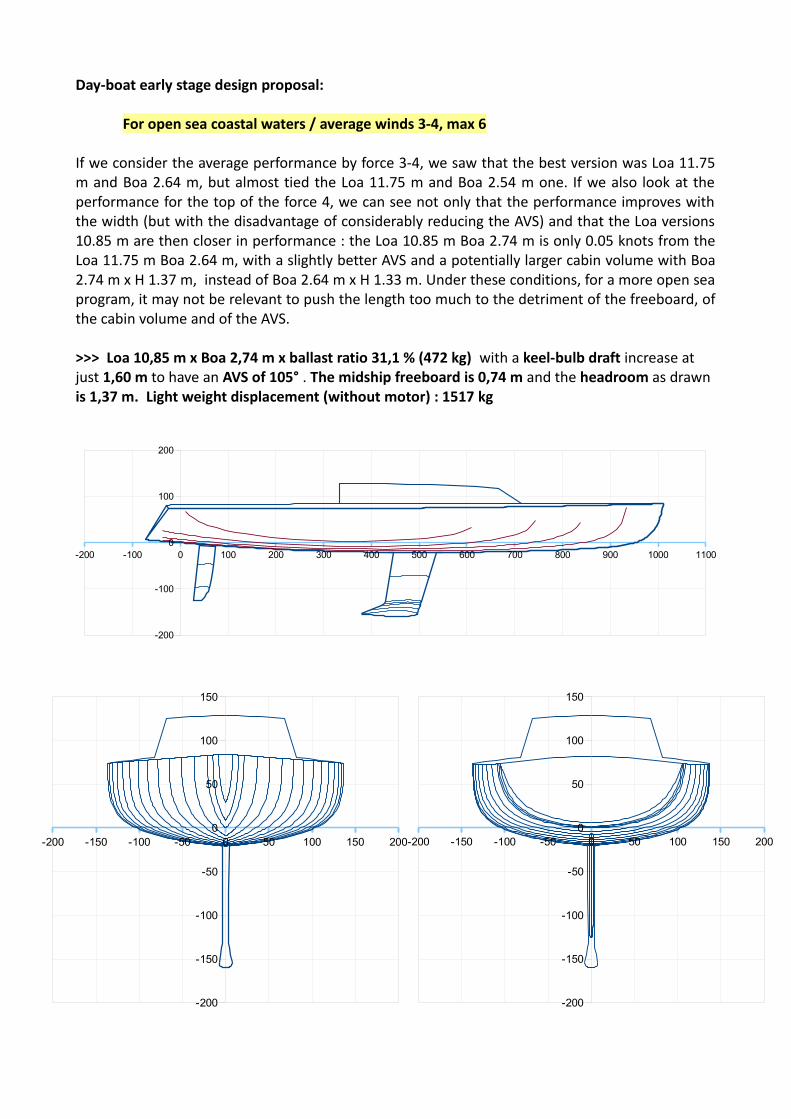
For open sea coastal waters / average winds 3-4, max 6
If we consider the average performance by force 3-4, we saw that the best version was Loa 11.75m and Boa 2.64 m, but almost tied the Loa 11.75 m and Boa 2.54 m one. If we also look at theperformance for the top of the force 4, we can see not only that the performance improves withthe width (but with the disadvantage of considerably reducing the AVS) and that the Loa versions10.85 m are then closer in performance : the Loa 10.85 m Boa 2.74 m is only 0.05 knots from theLoa 11.75 m Boa 2.64 m, with a slightly better AVS and a potentially larger cabin volume with Boa2.74 m x H 1.37 m, instead of Boa 2.64 m x H 1.33 m. Under these conditions, for a more open seaprogram, it may not be relevant to push the length too much to the detriment of the freeboard, ofthe cabin volume and of the AVS.
>>> Loa 10,85 m x Boa 2,74 m x ballast ratio 31,1 % (472 kg) with a keel-bulb draft increase at just 1,60 m to have an AVS of 105° . The midship freeboard is 0,74 m and the headroom as drawn is 1,37 m. Light weight displacement (without motor) : 1517 kg
-200 -100 0 100 200 300 400 500 600 700 800 900 1000 1100
-200
-100
0
100
200
-200 -150 -100 -50 0 50 100 150 200
-200
-150
-100
-50
0
50
100
150
-200 -150 -100 -50 0 50 100 150 200
-200
-150
-100
-50
0
50
100
150

-200 -100 0 100 200 300 400 500 600 700 800 900 1000 1100
-200
-100
0
100
200

SA : upwind 33,7 m2 (Main 16,6 m2 Jib 17,1 m2 ) , unchanged / the one of the investigation. downwind 68,4 m2 (Main 16,6 m2 Spi 51,8 m2)
-200 -100 0 100 200 300 400 500 600 700 800 900 1000 1100
-300
-200
-100
0
100
200
300
400
500
600
700
800
900
1000
1100
1200

My warmest thanks to Alain Lebeau who guides me within this approach, and realizes the 3D viewswhich illustrate this document.