
Jabiru Aircraft Model J120-C PILOT'S OPERATING HANDBOOK ... 120-C PIM.pdf · Max Manoeuvring Speed...
50
Jabiru Aircraft Model J120-C PILOT'S OPERATING HANDBOOK Revision 0 THIS DOCUMENT MUST BE CARRIED IN THE AIRCRAFT AT ALL TIMES
Transcript of Jabiru Aircraft Model J120-C PILOT'S OPERATING HANDBOOK ... 120-C PIM.pdf · Max Manoeuvring Speed...
Jabiru Aircraft
Model J120-C
PILOT'S OPERATING HANDBOOK
Revision 0
THIS DOCUMENT MUST BE CARRIED IN THE AIRCRAFT AT ALL TIMES

Jabiru Aircraft Pilot’s Operating Handbook
Model J120-C
JP-FM-10 Revision: 0 28 Nov 2007 Page 2 of 50
AIRCRAFT PARTICULARS
THIS AIRCRAFT MUST BE OPERATED IN ACCORDANCE WITH THE APPROVED DATA AND LIMITATIONS CONTAINED IN THIS MANUAL AT ALL TIMES.
Registration Marks: ____________
Manufacturer: Jabiru Aircraft Pty Ltd
Aircraft Serial Number: _________________
Certification Categories: Light Sport Aircraft
Any person finding this Manual is requested to return it to Jabiru Aircraft P/L.

Jabiru Aircraft Pilot’s Operating Handbook
Model J120-C
JP-FM-10 Revision: 0 28 Nov 2007 Page 3 of 50
AMENDMENT RECORD SHEET
Amendment Date
Affected Sections
Affected Pages Date Inserted
Signature

Jabiru Aircraft Pilot’s Operating Handbook
Model J120-C
JP-FM-10 Revision: 0 28 Nov 2007 Page 4 of 50
0.1 INTRODUCTION
This Operating Handbook has been prepared to comply with the requirements of ASTM F2245.
This Operating Handbook includes the information required of the Flight Training Supplement.
The basic handbook provides all the information, procedures and limitations required to operate the aircraft as a Light Sport Aircraft. Information, procedures and limitations relating specifically to other operations are provided in the appropriate supplement.
The operating procedures presented herein are the result of Jabiru Aircraft’s knowledge and experience gained up to the date of issue or amendment of this handbook. The handbook is not intended to be a guide for basic flight instruction or as a training manual. It may be used for operational purposes only if kept in a fully amended state. It contains all the information considered necessary to safely operate the aircraft.
The operator must be thoroughly familiar with the aircraft and the contents of this handbook before initial operation. Thereafter the handbook should be reviewed periodically to enable the operator to maintain the highest level of familiarity with the aircraft, its controls and recommended operating procedures.
0.2 PILOT’S OPERATING HANDBOOK (POH)
The handbook is valid only for the particular aircraft identified on the AIRCRAFT PARTICULARS page, and unless subsequently amended, refers to the aircraft as originally delivered from the factory. The handbook consists of the following:
Basic POH
The basic POH provides all required details of the standard aircraft and the procedures required to operate it in the LSA category. Apart from the listing in Section Error! Reference source not found., no other details of any optional equipment fitted at the factory will be found in the basic POH. Refer to the relevant supplement.
Supplements
Self contained supplements are provided in SECTION Error! Reference source not found. of the POH to provide details and procedures associated with the fitment of specified optional and special purpose equipment.
Amendments
Any amendments to any page of the POH is to have an amendment date. All amendments are to be incorporated as soon as possible after their receipt and details entered into the appropriate amendment record sheet.

Jabiru Aircraft Pilot’s Operating Handbook
Model J120-C
JP-FM-10 Revision: 0 28 Nov 2007 Page 5 of 50
0.3 WARNINGS, CAUTIONS & NOTES
Definitions used in the POH such as WARNING, CAUTION, NOTE are employed in the following context:
WARNING
Operating procedures, techniques, etc. which if not followed correctly, may result in personal injury or death.
CAUTION
Operating procedures, techniques, etc. which if not strictly observed, may result in damage to the aircraft or to its installed equipment.
NOTE
Operating procedures, techniques, etc. which it is considered essential to highlight.

Jabiru Aircraft Pilot’s Operating Handbook
Model J120-C
JP-FM-10 Revision: 0 28 Nov 2007 Page 6 of 50
0.4 THREE-VIEW DRAWING
Figure 1-1 Three View of the J120
Note: All dimensions in millimetres

Jabiru Aircraft Pilot’s Operating Handbook
Model J120-C
JP-FM-10 Revision: 0 28 Nov 2007 Page 7 of 50
0.5 SYMBOLS, ABBREVIATIONS AND TERMINOLOGY
0.5.1 General Symbols and Abbreviations
A Ampere AGL Above Ground Level AMSL Above Mean Sea Level AVGAS Aviation Gasoline BHP Brake Horse Power CASA Civil Aviation Safety Authority (Australia) CAO Civil Aviation Order (Australia) CAR Civil Aviation Regulation (Australia) °C Degrees Celsius CHT Cylinder Head Temperature cm Centimetre, centimetres DC Direct Current FAA Federal Aviation Administration (USA) °F Degrees Fahrenheit FAR Federal Aviation Regulation (USA) ft Foot, feet ft/min Feet per minute g Acceleration due to gravity Gal Gallon hPa Hectopascal, hectopascals HF High Frequency ICAO International Civil Aviation Organisation IFR Instrument Flight Rules IMC Instrument Meteorological Conditions in Inch, inches in Hg Inches of mercury in lbs Inch pounds ISA International Standard Atmosphere kg Kilogram kg/l Kilogram per litre kHz Kilohertz kts, K Knots kPa Kilopascals kW Kilowatt, kilowatts l Litre, litres lb Pound, pounds LH Left hand LHS Left hand side m Metre m
2 Square metre
m3 Cubic metre
mA Milli ampere MAC Mean Aerodynamic Chord max Maximum MHz Megahertz mm Millimetre min Minimum or minute MOGAS Automotive Fuel nm Nautical mile, nautical miles OAT Outside Air Temperature
Jabiru Aircraft Pilot’s Operating Handbook
Model J120-C
JP-FM-10 Revision: 0 28 Nov 2007 Page 8 of 50
PAX Passenger POH Pilots Operating Handbook PROP Propeller psi Pounds per square inch QTY Quantity qts Quarts RH Right Hand RHS Right Hand Side RON Fuel Octane Rating Scale (Research Octane Number) RPM Revolutions per minute SAE Society of Automotive Engineers sec Seconds SQ Square STBY Standby TBO Time between overhauls T/O Take Off U/S Unserviceable USG US Gallon US Gal US Gallon V Volts VFR Visual Flight Rules VHF Very High Frequency VMC Visual Meteorological Conditions
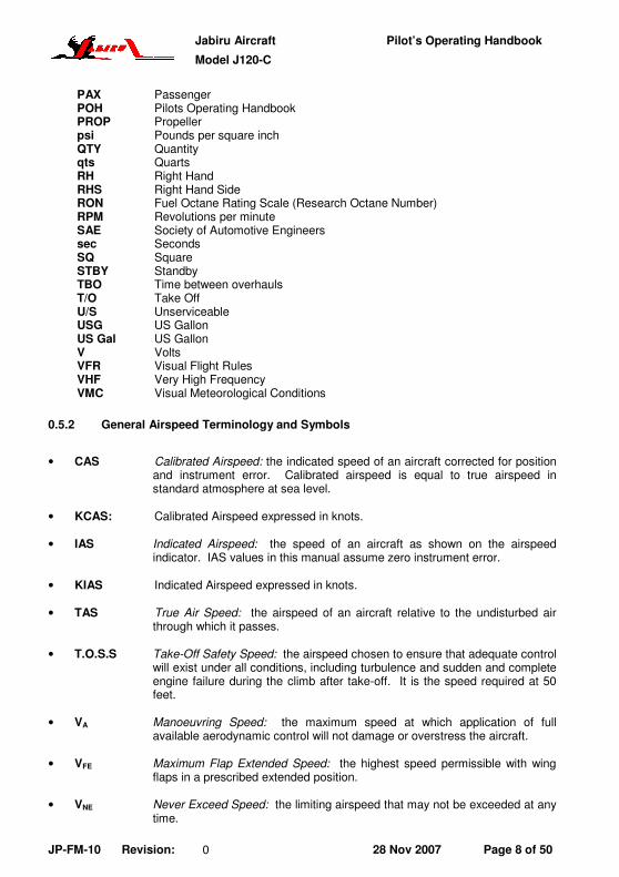
0.5.2 General Airspeed Terminology and Symbols
• CAS Calibrated Airspeed: the indicated speed of an aircraft corrected for position and instrument error. Calibrated airspeed is equal to true airspeed in standard atmosphere at sea level.
• KCAS: Calibrated Airspeed expressed in knots.
• IAS Indicated Airspeed: the speed of an aircraft as shown on the airspeed indicator. IAS values in this manual assume zero instrument error.
• KIAS Indicated Airspeed expressed in knots.
• TAS True Air Speed: the airspeed of an aircraft relative to the undisturbed air through which it passes.
• T.O.S.S Take-Off Safety Speed: the airspeed chosen to ensure that adequate control will exist under all conditions, including turbulence and sudden and complete engine failure during the climb after take-off. It is the speed required at 50 feet.
• VA Manoeuvring Speed: the maximum speed at which application of full available aerodynamic control will not damage or overstress the aircraft.
• VFE Maximum Flap Extended Speed: the highest speed permissible with wing flaps in a prescribed extended position.
• VNE Never Exceed Speed: the limiting airspeed that may not be exceeded at any time.
Jabiru Aircraft Pilot’s Operating Handbook
Model J120-C
JP-FM-10 Revision: 0 28 Nov 2007 Page 9 of 50
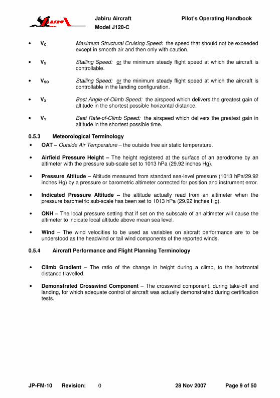
• VC Maximum Structural Cruising Speed: the speed that should not be exceeded except in smooth air and then only with caution.
• VS Stalling Speed: or the minimum steady flight speed at which the aircraft is controllable.
• VSO Stalling Speed: or the minimum steady flight speed at which the aircraft is controllable in the landing configuration.
• VX Best Angle-of-Climb Speed: the airspeed which delivers the greatest gain of altitude in the shortest possible horizontal distance.
• VY Best Rate-of-Climb Speed: the airspeed which delivers the greatest gain in altitude in the shortest possible time.
0.5.3 Meteorological Terminology
• OAT – Outside Air Temperature – the outside free air static temperature.
• Airfield Pressure Height – The height registered at the surface of an aerodrome by an altimeter with the pressure sub-scale set to 1013 hPa (29.92 inches Hg).
• Pressure Altitude – Altitude measured from standard sea-level pressure (1013 hPa/29.92 inches Hg) by a pressure or barometric altimeter corrected for position and instrument error.
• Indicated Pressure Altitude – the altitude actually read from an altimeter when the pressure barometric sub-scale has been set to 1013 hPa (29.92 inches Hg).
• QNH – The local pressure setting that if set on the subscale of an altimeter will cause the altimeter to indicate local altitude above mean sea level.
• Wind – The wind velocities to be used as variables on aircraft performance are to be understood as the headwind or tail wind components of the reported winds.
0.5.4 Aircraft Performance and Flight Planning Terminology
• Climb Gradient – The ratio of the change in height during a climb, to the horizontal distance travelled.
• Demonstrated Crosswind Component – The crosswind component, during take-off and landing, for which adequate control of aircraft was actually demonstrated during certification tests.

Jabiru Aircraft Pilot’s Operating Handbook
Model J120-C
JP-FM-10 Revision: 0 28 Nov 2007 Page 10 of 50
0.5.5 Weight and Balance Terminology
• Datum – An imaginary vertical plane from which all horizontal distances are measured for balance purposes.
• Station – A location along the aircraft fuselage usually given in terms of distance from the reference datum.
• Arm – The horizontal distance from the reference datum to the centre of gravity (C of G) of an item.
• Moment – The product of the weight of an item multiplied by its arm.
• Index Unit – Moment divided by a constant. Used to simplify balance calculations by reducing the number of digits.
• Centre of Gravity (C of G) – The point at which an aircraft would balance if suspended. The distance from the C of G to the reference datum can be found by dividing the total moment by the total weight of the aircraft.
• C of G Arm – The arm obtained by adding the aircraft's individual moments and dividing the sum by the total weight.
• C of G Limits – The extreme centre of gravity locations within which the aircraft must be operated at a given weight.
• Useable Fuel – The quantity of fuel available for flight planning purposes.
• Unusable Fuel – The quantity of fuel (determined under adverse fuel flow conditions) that is not available for flight.
• Empty Weight – Weight of aircraft with unusable fuel and full oil.
• Useful Load – Difference between take-off weight, and basic empty weight.
• Maximum Take-Off Weight – Maximum weight approved for take-off.

Jabiru Aircraft Pilot’s Operating Handbook
Model J120-C
JP-FM-10 Revision: 0 28 Nov 2007 Page 11 of 50
0.6 USE OF METRIC/IMPERIAL UNITS
This POH uses the metric system as the basic system of measurement. Where common usage or available instrumentation refer to the Imperial/US unit system, both units are quoted. The following conversion factors are presented as a ready reference to the conversion factors that have been used in this manual as well as supplying some others that may be found useful.
1 Pound (lb) = 0.4536 Kilogram (kg) 1 Pound per sq in (psi) = 6.895 Kilopascal (kPa) 1 Inch (in) = 25.4 Millimetres (mm) 1 Foot (ft) = 0.3048 Metre (m) 1 Statute mile = 1.609 Kilometres (km) 1 Nautical mile (NM) = 1.852 Kilometres (km) 1 Millibar (mb) = 1 Hectopascal (hPa) 1 Millibar (mb) = 0.1 Kilopascal (kPa) 1 Imperial gallon = 4.546 Litres (l) 1 US gallon = 3.785 Litres (l) 1 US quart = 0.946 Litre (l) 1 Cubic foot (ft
3) = 28.317 Litres (l)
1 Acre = 0.4047 Hectares
1 Degree Fahrenheit (ΕF) = [1.8 x ΕC]+32 1 Inch Pound (in lb) = 0.113 Newton Metres (Nm) 1 Foot Pound (ft lb) = 1.356 Newton Metres (Nm)

Jabiru Aircraft Pilot’s Operating Handbook
Model J120-C
JP-FM-10 Revision: 0 28 Nov 2007 Page 12 of 50
TABLE OF CONTENTS
0.1 INTRODUCTION ............................................................................1-4
0.2 PILOT’S OPERATING HANDBOOK (POH)....................................1-4
0.3 WARNINGS, CAUTIONS & NOTES ...............................................1-5
0.4 THREE-VIEW DRAWING ...............................................................1-6
0.5 SYMBOLS, ABBREVIATIONS AND TERMINOLOGY....................1-7
0.6 USE OF METRIC/IMPERIAL UNITS.............................................1-11
1 SECTION 1 - GENERAL....................................................................1-14
1.1 MANUFACTURERS STATEMENT OF COMPLIANCE ................1-14
1.2 MANUFACTURER DETAILS........................................................1-15
1.3 LIGHT SPORT AIRCRAFT NOTIFICATION.................................1-15
1.4 J120-C PERFORMANCE AND SPECIFICATION SUMMARY .....1-15
2 SECTION 2 – AIRPLANE & SYSTEMS DESCRIPTION...................2-16
2.1 ENGINE...........................................................................................2-16
2.2 PROPELLER ....................................................................................2-16
2.3 FUEL ..............................................................................................2-16
2.4 ENGINE OIL.....................................................................................2-16
2.5 CENTRE OF GRAVITY LIMITS ....................................................2-16
3 SECTION 3 – OPERATING LIMITATIONS .......................................3-19
3.1 KINDS OF OPERATION ...............................................................3-19
3.2 AIRSPEED LIMITATIONS ............................................................3-19
3.3 CROSSWIND....................................................................................3-19
3.4 AIRCRAFT SERVICE CEILING ............................................................3-19
3.5 LOAD FACTORS ..........................................................................3-19
3.6 PROHIBITED MANOEUVRES ..............................................................3-19
3.7 POWER PLANT LIMITATIONS ....................................................3-20
3.8 FUEL GRADE...................................................................................3-20
3.9 POWER PLANT INSTRUMENT MARKINGS ...............................3-21
3.10 REQUIRED EFIS DISPLAYS........................................................3-21
3.11 OTHER LIMITATIONS..................................................................3-21
3.12 PLACARDS...................................................................................3-21
4 SECTION 4 – WEIGHT & BALANCE INFORMATION .....................4-26
4.1 CENTRE OF GRAVITY LIMITS ....................................................4-26
4.2 TRIM SHEETS..................................................................................4-29
5 SECTION 5 – PERFORMANCE ........................................................5-33
5.1 TAKE OFF AND LANDING DISTANCES......................................5-33
5.2 RATE OF CLIMB...........................................................................5-33
5.3 CRUISE SPEEDS / RPM / FUEL CONSUMPTION ......................5-33

Jabiru Aircraft Pilot’s Operating Handbook
Model J120-C
JP-FM-10 Revision: 0 28 Nov 2007 Page 13 of 50
5.4 AIRSPEED INDICATOR SYSTEM CALIBRATION.................................... 5-34
6 SECTION 6 - EMERGENCY PROCEDURES ................................... 6-35
6.1 GENERAL .................................................................................... 6-35
6.2 AIRSPEEDS FOR EMERGENCY OPERATIONS........................ 6-35
6.3 EMERGENCY PROCEDURES CHECK LISTS............................ 6-35
7 SECTION 7 – NORMAL PROCEDURES.......................................... 7-40
7.1 GENERAL .................................................................................... 7-40
7.2 SPEEDS FOR NORMAL OPERATION........................................ 7-40
7.3 PREFLIGHT INSPECTION .......................................................... 7-41
7.4 NORMAL PROCEDURES CHECK LISTS ................................... 7-44
8 SECTION 8 – GROUND HANDLING & SERVICING ....................... 8-47
8 SECTION 8 – GROUND HANDLING & SERVICING ....................... 8-47
8.1 FUEL ............................................................................................ 8-47
8.2 OIL................................................................................................ 8-48
8.3 BRAKES....................................................................................... 8-48
9 SECTION 9 – SUPPLEMENTS ......................................................... 9-49
9.1 INTRODUCTION.......................................................................... 9-49
9.2 SUPPLEMENT LOG – JABIRU AIRCRAFT SUPPLEMENTS ..... 9-50

Jabiru Aircraft Pilot’s Operating Handbook
Model J120-C
JP-FM-10 Revision: 0 28 Nov 2007 Page 14 of 50
1 SECTION 1 - GENERAL
1.1 MANUFACTURERS STATEMENT OF COMPLIANCE
INSERT COPY OF MANUFACTURERS STATEMENT OF COMPLIANCE

Jabiru Aircraft Pilot’s Operating Handbook
Model J120-C
JP-FM-10 Revision: 0 28 Nov 2007 Page 15 of 50
1.2 MANUFACTURER DETAILS
Jabiru Aircraft P/L
PO Box 5186
Bundaberg West,
QLD 4670
Phone: 07 4155 1778
Fax: 07 4155 2669
Email: [email protected]
Street Address:
Jabiru Aircraft
Airport Drive, Hinkler Airport
Bundaberg
QLD 4670
1.3 LIGHT SPORT AIRCRAFT NOTIFICATION
There are inherent risks in the participation in recreational aviation aircraft. Operators and passengers of recreational aviation aircraft, by participation, accept the risks inherent in such participation of which the ordinary prudent person is or should be aware. Pilots and passengers have a duty to exercise good judgment and act in a responsible manner while using the aircraft and to obey all oral or written warnings, or both, prior to or during use of the aircraft, or both.
1.4 J120-C PERFORMANCE AND SPECIFICATION SUMMARY
Gross Weight 500kg (11102 lb)
Top Speed at Sea Level 120 KCAS
Full Fuel Range1
380 nm at 75% power
450 nm at most efficient power setting
Rate of Climb at Sea Level2 500 fpm
Take-Off Distance 400 m
Landing Distance 300 m
Stall Speed Clean 49 KCAS
Stall Speed Flaps Full Down 45 KCAS
Fuel Capacity 64 L Useable
Approved Fuels AVGAS or MOGAS with RON of 95 or higher.
Maximum Engine Power 85 hp @ 3300 RPM.
Refer to the main body of this handbook below for more information.
1 Range with 45 minute reserve at stated power setting
2 At Gross Weight, ICAO Standard Atmosphere

Jabiru Aircraft Pilot’s Operating Handbook
Model J120-C
JP-FM-10 Revision: 0 28 Nov 2007 Page 16 of 50
2 SECTION 2 – AIRPLANE & SYSTEMS DESCRIPTION
2.1 Engine
Manufacturer: Jabiru Aircraft Pty Ltd
Model: Jabiru 2200-B
2.2 Propeller
Manufacturer: Jabiru Aircraft Pty Ltd
Model: C000262-D60P42
Type: Wooden, Fixed Pitch
Number of blades: 2
Diameter: 1524 mm (60 in)
Pitch 1067 mm (42 in)
Max RPM: 3300
2.3 Fuel
Capacity: 64L Useable Grade: Avgas 100LL
Avgas 100/130 MOGAS with minimum Octane Rating of 95 RON
1 may be used.
Do not use fuel additives such as Octane Boosters. Refer to Section 3 for additional details.
2.4 Engine Oil
Jabiru Aircraft approves lubricating oils of any brand name conforming to specifications MIL-L-6082 for straight mineral oil and MIL-L-22851 for ashless dispersant oil.
Refer to Section Error! Reference source not found. for additional details.
2.5 CENTRE OF GRAVITY LIMITS
Forward Limit:
1601-mm (63.03”, 20%MAC) aft of datum up to & including 420 kg (926lb)
1661-mm (63.39”, 26.1%MAC) aft of datum at 500kg (1190lb)
Linear variation between points.
Aft Limit 1695-mm (66.73”, 29.5%) aft of datum at all weights
Datum 1403mm fwd of RHS Wing Leading Edge
Levelling Means

Jabiru Aircraft Pilot’s Operating Handbook
Model J120-C
JP-FM-10 Revision: 0 28 Nov 2007 Page 17 of 50
Longitudinal Spirit Level placed on the trim decal on the centre console.
Lateral Spirit Level placed on the flap cross shaft.
Arms
Arm for Front Seat Station 1688-mm aft of datum
Arm for Baggage On Shelf 2280-mm aft of datum
Fuel Station 2280-mm aft of datum
Table 2.7
Refer to Section 4 for additional details
2.5.1 Minimum Equipment List
Opt.
Code Description
Weight
kg (lb)
Arm
mm (in)
Firewall Fwd
Engine: Jabiru 2200. Includes starter, alternator, carburettor, muffler, spark plugs, prop flange extension and oil filter assembly
61kg
(135lb)
280mm
(11.02in)
Oil Cooler (empty): P/No. PH4A015N 0.5kg
(1.1lb)
280mm
(11.02in)
Propeller: P/No. C000242-60D42P 1.7kg
(3.7lb)
-60mm
(2.36in)
Spinner Assembly: 4A189A0D 0.6kg
(1.3lb)
-60mm
(2.36in)
Instruments
Airspeed Indicator 0.5kg
(1.1lb)
1110mm
(43.70in)
Altimeter 0.8kg
(1.8lb)
1110mm
(43.70in)
O EFIS: Dynon EFIS-D10A 0.7kg
(1.5lb)
1110mm
(43.70in)
Oil Pressure Gauge 0.2kg
(0.4lb)
1110mm
(43.70in)
Oil Temperature Gauge 0.2kg
(0.4lb)
1110mm
(43.70in)
Tachometer 0.4kg
(0.9lb)
1110mm
(43.70in)
Cylinder Head Temperature 0.2kg
(0.4lb)
1110mm
(43.70in)

Jabiru Aircraft Pilot’s Operating Handbook
Model J120-C
JP-FM-10 Revision: 0 28 Nov 2007 Page 18 of 50
Opt.
Code Description
Weight
kg (lb)
Arm
mm (in)
Electrical Equipment
Battery (Odyssey PC625) 6.7kg
(14.8lb)
910mm
(35.83in)
VHF COMM #1: 0.5kg
(1.1lb)
1110mm
(43.70in)
O Transponder 0.7kg
(1.5lb)
1110mm
(43.70in)
Headsets 0.6kg
(1.3lb)
1688mm
(66.46in)
O Ameri-King Altitude Encoder (AK-350) 0.8kg
(1.8lb)
1000mm
(39.37in)
Miscellaneous
Baggage Restraint Straps (Each) 0.1kg
(0.2lb)
2280mm
(89.76in)
Seat Covers Cloth: 1.0kg
(2.2lb)
1688mm
(66.46in)
O Seat Covers Sheepskin 1.5kg
(3.3lb)
304mm
(11.97in)
O Tool Kit 1.5kg
(3.3lb)
804mm
(31.65in)
Flight Manual 0.4kg
(0.9lb)
-210mm
(-8.27in)
Compass 0.4kg
(0.9lb))
-266mm
(-10.47in)
Door Pockets 0.1kg
(0.2lb)
1110mm
(43.70in)
Additions/Deletions
Table 2.11.2
Jabiru Aircraft Pilot’s Operating Handbook
Model J120-C
JP-FM-10 Revision: 0 28 Nov 2007 Page 19 of 50
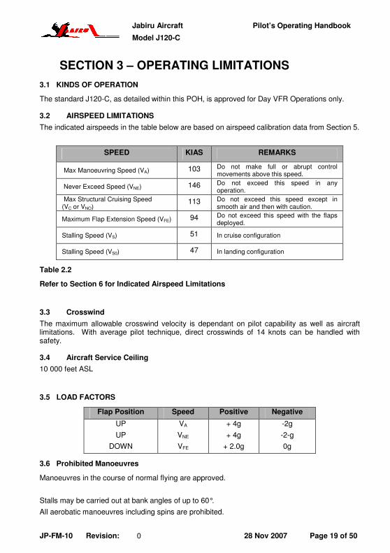
3 SECTION 3 – OPERATING LIMITATIONS
3.1 KINDS OF OPERATION
The standard J120-C, as detailed within this POH, is approved for Day VFR Operations only.
3.2 AIRSPEED LIMITATIONS
The indicated airspeeds in the table below are based on airspeed calibration data from Section 5.
SPEED KIAS REMARKS
Max Manoeuvring Speed (VA) 103 Do not make full or abrupt control movements above this speed.
Never Exceed Speed (VNE) 146 Do not exceed this speed in any operation.
Max Structural Cruising Speed (VC or VNO)
113 Do not exceed this speed except in smooth air and then with caution.
Maximum Flap Extension Speed (VFE) 94 Do not exceed this speed with the flaps deployed.
Stalling Speed (VS) 51 In cruise configuration
Stalling Speed (VS0) 47 In landing configuration
Table 2.2
Refer to Section 6 for Indicated Airspeed Limitations
3.3 Crosswind
The maximum allowable crosswind velocity is dependant on pilot capability as well as aircraft limitations. With average pilot technique, direct crosswinds of 14 knots can be handled with safety.
3.4 Aircraft Service Ceiling
10 000 feet ASL
3.5 LOAD FACTORS
Flap Position Speed Positive Negative
UP
UP
DOWN
VA
VNE
VFE
+ 4g
+ 4g
+ 2.0g
-2g
-2-g
0g
3.6 Prohibited Manoeuvres
Manoeuvres in the course of normal flying are approved.
Stalls may be carried out at bank angles of up to 60°.
All aerobatic manoeuvres including spins are prohibited.

Jabiru Aircraft Pilot’s Operating Handbook
Model J120-C
JP-FM-10 Revision: 0 28 Nov 2007 Page 20 of 50
3.7 POWER PLANT LIMITATIONS
Maximum Temperatures
Fuel Pressure Limits
Oil Pressure
Limits
POWER
RP
M
Cyl Head Oil Min Max Min Max
Absolute Limits
Maximum Take-Off (85 BHP)
3300 200 °C (392°F) (Note #1)
118°C (244°F)
5 kPa (0.75psi)
20 kPa (3psi)
220 kPa (31 psi)
525 kPa (76psi)
Continuous Limits
Maximum Cont
(85 BHP) 3300
180°C (356°F)
100°C (212°F)
5 kPa (0.75psi)
20 kPa (3psi)
220 kPa (31 psi)
525 kPa (76 psi)
Limits For Ground Running
N/A N/A 180°C (356°F) (Note #2)
100°C (212°F) (Note #2)
5 kPa (0.75psi)
20 kPa (3psi)
80 kPa (11 psi)
525 kPa (76 psi)
Note #1 Time with CHT at between 180°C and 200°C is not to exceed 5 Minutes
Note #2 If temperature limits are reached, shut the engine down or cool it by pointing the aircraft into wind.
Table 2.4.2
Other limits are as follows:
• Minimum oil pressure at idle: 80 kPa (11 psi)
• Maximum oil pressure at start: 525 kPa (76 psi)
3.8 Fuel Grade
Grade: Avgas 100LL Avgas 100/130 MOGAS with minimum Octane Rating of 95 RON
1 may be used.
Do not use fuel additives such as Octane Boosters.
NOTE
As there are significant variations possible even between automotive fuels with the same values of RON, MON or AKI, Jabiru Aircraft strongly recommend using AVGAS. Automotive fuels should only be used where AVGAS is not available, and if used, must have the highest anti-detonation rating practically available.
CAUTION
In the J120-C Jabiru Aircraft allow the use of Ethanol additive to fuel up to a ratio of 10%. However, owners must be aware of the additional operational risks and maintenance
requirements for using Ethanol additives. Section Error! Reference source not found. contains additional information.
3.8.1 Lubricating Oil
Oil Capacity 2.2 Litres.
Refer to Section 8 for additional details.

Jabiru Aircraft Pilot’s Operating Handbook
Model J120-C
JP-FM-10 Revision: 0 28 Nov 2007 Page 21 of 50
3.9 POWER PLANT INSTRUMENT MARKINGS
Instrument Red Line
Minimum Limit
Green Arc
Normal Operating
Red Arc/Line
Maximum Limit
Yellow Arc Precautionary
Range
Tachometer - - 3300 RPM -
Cylinder Head Temperature
- Up to 180°C
(356°F)
200°C
(392°F)
180°C - 200°C
(356° - 392°F)
Oil Pressure 80 kPa
(11 psi)
220 - 525 kPa
(31 – 76 psi)
525 kPa
(76 psi)
80 - 220 kPa
(11- 31psi)
Oil Temperature 15°C
(59°F)
80 - 100°C
(176° - 212°F)
118°C
(244°F)
100°C - 118°C
(212 °- 244°F)
Fuel Pressure 5 kPa
(0.75psi)
5 – 20 kPa
(0.75 – 3 psi)
20 kPa
3 psi -
Voltage - 10.5 – 15 Volts - -
Table 2.5
3.10 REQUIRED EFIS DISPLAYS
Where aircraft are equipped with an EFIS display, they are programmed to display limitations and alarms etc as a part of their installation into the aircraft. These limitations must be displayed for the aircraft to comply with it’s certification basis. If adjustments are required to the displays the work must be carried out before further flight by an authorised person with reference to the user manuals for the instruments, and the following lists give the minimum information which must be displayed.
3.10.1 Required EFIS limitation displays:
• Never exceed speed, VNE (Red line speed, top of yellow arc)
• Maximum structural cruising speed, VC (Top of green arc, bottom of yellow arc)
• Maximum Flap Extension speed, VFE (Top of white arc)
• Stall speed with full flap, VS0 (Bottom of white arc)
• Stall speed clean, VS1 (bottom of green arc)
3.11 OTHER LIMITATIONS
• Smoking is prohibited.
• In-Cabin noise levels exceed 95 db. Hearing protection must be worn.
3.12 PLACARDS
The following placards are required, and are to be located in the proximity indicated. Each placard is to contain wording conforming with the illustrations. The shape and layout of production items may vary between individual aircraft. Consult the manufacturer for individual aircraft placard variations.

Jabiru Aircraft Pilot’s Operating Handbook
Model J120-C
JP-FM-10 Revision: 0 28 Nov 2007 Page 22 of 50
3.12.1 Cockpit Placards General
Warning Placard
P/No. 5A092A0D
Fitted on the rear Face of the Forward Wing Spar Carry-through Beam in the Cabin Ceiling.
LSA Placard
P/No. 5A060A0D
Fitted on the rear Face of the Forward Wing Spar Carry-through Beam in the Cabin Ceiling.
No Intentional Spins.
P/No. 5A072A0D
Fit to Instrument Panel
Owners Manual
P/No 5A075A0D
Fitted to Inside of RH Door above the Door Pocket.
No Smoking
P/No. 5A035A0D
Fit to instrument panel.
Door Open LHS
P/No 5027094 OPEN
Fitted to the Outsides of LH Door Above the Door Catch Lever
Door Open RHS
P/No 5028094 OPEN
Fitted to the outside of RH Door Above the Door Catch Level
Fuel Contents
P/No. 5090064
Fitted to centre of front face of fuel tank between seats

Jabiru Aircraft Pilot’s Operating Handbook
Model J120-C
JP-FM-10 Revision: 0 28 Nov 2007 Page 23 of 50
Compass Card
P/No. 5123024
Fit in compass card holder attached to compass.
Baggage
P/No. 5A037A0D
Fit to right side fuselage wall immediately below window.
Baggage
P/No. 5111154
Fit to inside of fuselage on right side just below rear quarter window. Locate vertical line in line with rear of fuel tank.
Loading Limitations
P/No 5118024
Fitted on inside of fuselage of RHS of cabin below rear quarter window.
Table 2.15.1

Jabiru Aircraft Pilot’s Operating Handbook
Model J120-C
JP-FM-10 Revision: 0 28 Nov 2007 Page 24 of 50
� Cockpit Controls
Trim Position
P/No. 5024094
(1 OFF)
Fit to centre console beside of elevator fwd stop, above trim lever.
Fuel Tap Position
P/No 502319N
Fitted on the centre console beside the Fuel Selector Valve
Carby Heat
P/No 5A030A0D
Fitted to lower central section of instrument panel.
Table 2.15.2
� External Fuselage
Static Port
P/No 5043094
STATIC VENT KEEP CLEAR
Attach to LHS of Vertical Fin in line with Static Tube
Fuel Grade- Wing Tanks
P/No 5091064
Attach to fuselage adjacent to Fuel Filler Cap.
Nose Wheel Inflation.
P/No. 5A017A0D
Attach to left side of nose wheel spat.
Main Wheel Inflation.
P/No. 5A018A0D

Jabiru Aircraft Pilot’s Operating Handbook
Model J120-C
JP-FM-10 Revision: 0 28 Nov 2007 Page 25 of 50
Attach to outsides of main wheel spats
Engine Oil
P/No. 5A008A0D
Attach to inner face of door in top engine cowl.
Dipstick Inside
P/No. 5A007A0D
Fit to outside of oil door in upper engine cowl.
Door Lean.
P/No. 5A013A0D
Fit to top of doors.
Wing Bolt Tightening
P/No 5039094
Qty 8 Required
DANGER DO NOT TIGHTEN
Attach to the fuselage and wings beside each wing, and lift strut attachment fitting.
Earth on Post
P/No. 5A066A0D
Attach to upper wing skin beside fuel filler earth post.
No Step
P/No. 5A006A0D
Qty 2 required.
Fit to top of main wheel spats
Earth on Exhaust
P/No. 5029094
Attach to the lower fuselage on the pilot’s side immediately above the exhaust outlet pipe.
Table 2.15.3

Jabiru Aircraft Pilot’s Operating Handbook
Model J120-C
JP-FM-10 Revision: 0 28 Nov 2007 Page 26 of 50
4 SECTION 4 – WEIGHT & BALANCE INFORMATION
4.1 CENTRE OF GRAVITY LIMITS
Forward Limit:
1601-mm (63.03”, 20%MAC) aft of datum up to & including 420 kg (926lb)
1661-mm (63.39”, 26.1%MAC) aft of datum at 500kg (1190lb)
Linear variation between points.
Aft Limit 1695-mm (66.73”, 29.5%) aft of datum at all weights
Datum 1403mm fwd of RHS Wing Leading Edge
Levelling Means
Longitudinal Spirit Level placed on the trim decal on the centre console.
Lateral Spirit Level placed on the flap cross shaft.
Arms
Arm for Front Seat Station 1688-mm aft of datum
Arm for Baggage On Shelf 2280-mm aft of datum
Fuel Station 2280-mm aft of datum
Table 6.4 – Centre of Gravity Limits
Figure 6.3.1 – Baggage Zones
Baggage is restrained using the straps fitted in the baggage areas.

Jabiru Aircraft Pilot’s Operating Handbook
Model J120-C
JP-FM-10 Revision: 0 28 Nov 2007 Page 27 of 50
INSERT PAGES 6.2 & 6.3 FROM WEIGHING SPREADSHEET HERE

Jabiru Aircraft Pilot’s Operating Handbook
Model J120-C
JP-FM-10 Revision: 0 28 Nov 2007 Page 28 of 50
INSERT WEIGHT & BALANCE RECORD FROM WEIGHING SPREADSHEET IN PLACE OF THIS PAGE.

Jabiru Aircraft Pilot’s Operating Handbook
Model J120-C
JP-FM-10 Revision: 0 28 Nov 2007 Page 29 of 50
4.2 Trim Sheets
A metric trim sheet has been provided. An example loading has been worked through for reference.
4.2.1 Trim Sheet Index Units
To use the trim sheets the aircraft’s weight and balance information must be converted to “Trim Sheet Index Units” using the formula below:
Trim Sheet Index Units = Aircraft Weight x (Arm – 1403)
1000
“Aircraft Weight” and “Arm” are written onto the aircraft’s Load Data Sheet.
For example, an aircraft with “Aircraft Weight” of 260kg and “Arm” of 1590mm has a Trim Sheet Index Unit of 48.62 This is used for the starting point of using the Trim Sheets.
Calculate Aircraft Weights
1-1 Use the Aircraft Empty Weight obtained from the latest aircraft weighing records to enter the vertical “Aircraft Empty Weight Scale” on right hand side of the chart.
1-2 Move horizontally to the left into the next scale which is the “Crew Weight” Scale.
1-3 Move vertically downward one line on this scale for each 10-kg of weight that is placed on the front seats, and mark a point.
1-4 Move horizontally to the left from the point made in Step 1-3 to enter the next scale which is the “Baggage Weight” Scale.
1-5 Move vertically downward one line on this scale for each 5-kg of weight that is placed in Baggage Zone and mark a point.
1-6 Move horizontally to the left from the point made in Step 1-7 to enter the next scale which is the “Fuel Quantity” Scale and mark a point, This point is the “Zero Fuel Weight Reference Point”
1-7 Move Horizontally to the left of the “Zero Fuel Reference Point” and Mark a “Zero Fuel Weight Line” across the “Aircraft Trim Condition” Graph.
1-8 From the “Zero Fuel Point” on the “Fuel Quantity Scale” (marked in Step 1-8), move vertically downward one line for each 10-litres of fuel being carried at the take-off condition. Mark this “Take-Off Fuel Point” on the scale.
1-9 Move horizontally to the left, and mark a “Take-Off Fuel Weight Line” across the “Aircraft Trim Condition” graph.

Jabiru Aircraft Pilot’s Operating Handbook
Model J120-C
JP-FM-10 Revision: 0 28 Nov 2007 Page 30 of 50
Calculating the Operating CG Locations
2-1. Take the calculated Empty Weight Trim Index and mark it’s position on the Aircraft Index Units Ladder at the top of the sheet.
2-2 Draw a vertical line down from the point marked above to intersect with a sloping line in the “Crew Index Units” scale and mark this point.
2-3 Calculate the weight of the crew and round this value to the nearest 10-kg.
2-4 Move horizontally to the right from the point marked in Step 2-2 one line for each 10-kg of load calculated. (i.e. 60-kg = 6 lines) and mark a point at this location.
2-5 Draw a vertical line down from the point marked above to intersect with a sloping line in the Baggage Area scale and mark this point.
2-6 Calculate the weight that will be placed Baggage Area and round this value to the nearest 5-kg.
2-7 Move horizontally to the right from the point marked in Step 2-5 one line for each 5-kg of load calculated. (i.e. 20-kg = 4 lines) and mark a point at this location.
2-8 Drop a vertical line down from the point marked in Step 2-10 to intersect a sloping line in “Fuel Chart”, and mark a point at this location.
2-9 Continue the Vertical Line began in Step 2-11 down to intersect with the “Zero Fuel Weight Line” drawn in Step 1-7. mark this point as the “ZERO FUEL Condition”
2-10 Move horizontally to the right from the point marked in Step 2-11 in the “Take-Off Fuel Box”, one line for each 10 liters of take-off fuel, and mark this point.
2-11 Move vertically downward from the take-off fuel point marked in Step 2-13 to intersect with the “Take-Off Fuel Weight Line” marked in Step 1-9. Mark this point the “Take-Off Condition”
4.2.2 Allowable Loading Conditions
An allowable loading condition exists when both the “Zero Fuel Condition”, and the “Take-Off Condition” fall with the area bounded by the Line in the Aircraft Trim Conditions Box.
For reference, the example below shows two 80kg people, 5kg in Baggage Zone and 60L of fuel. The aircraft’s starting Index Unit is 48.6 at 260kg.

Jabiru Aircraft Pilot’s Operating Handbook
Model J120-C
JP-FM-10 Revision: 0 28 Nov 2007 Page 31 of 50
EXAMPLE
45 55 65 75 85 95 105 115 125 135 145
Crew Index Units - Come right 1 line per 10kg Crew Weight.
-530
-510
-490
-470
-450
-430
-410
-390
-370
-350
-330
-310
-290
-270
-250
Cre
w L
ad
de
r
Go d
ow
n 1
lin
e
per
10kg
cre
w
weig
ht.
-530
-510
-490
-470
-450
-430
-410
-390
-370
-350
-330
-310
-290
-270
-250
Ba
gg
ag
e
La
dd
er
Go d
ow
n 1
line
pe
r 5kg
Fu
el L
ad
de
r
Go d
ow
n 1
line
pe
r 10
L
fue
l.
Air
cra
ft
Em
pty
We
igh
t
Sta
rt a
t th
e
air
cra
ft's
em
pty
w
eig
ht
Aircraft Index Units
Fuel Index Units - Come right 1 line per 10L fuel added.
Baggage Index Units - Come right 1 line per 5kg added
STEP 1: Start at the empty aircraft's index
STEP 3: Draw a line down from the Aircraft Index to
the Crew Index ladder. Move 1 line right for every
10kg of crew, every 5kg in Baggage Zone.
STEP 4: Draw a line straight down from Baggage
Zone Index to the Fuel Index. Move 1 line right for
every 10L of Fuel.
STEP 5: Starting from the aircraft empty
weight, draw a line as shown, coming down 1
line per 10kg crew weight, 1 line per 5 kg
baggage and 1 line per 10 Litres of fuel.
Step 6: Check that the aircraft's CG position is
within the envelope with BOTH the fuel at the
start of the flight and at zero fuel.
STEP 3
STEP 4
STEP 3A
Figure 6-3a – Loading Trim Sheet Example

Jabiru Aircraft Pilot’s Operating Handbook
Model J120-C
JP-FM-10 Revision: 0 28 Nov 2007 Page 32 of 50
ORIGINAL
45 55 65 75 85 95 105 115 125 135 145
z
-530
-510
-490
-470
-450
-430
-410
-390
-370
-350
-330
-310
-290
-270
-250
Cre
w L
ad
der
Go
do
wn 1
lin
e
pe
r 10
kg
cre
w
we
ight.
-530
-510
-490
-470
-450
-430
-410
-390
-370
-350
-330
-310
-290
-270
-250
Ba
gg
ag
e
La
dd
er
Go d
ow
n 1
lin
e
pe
r 5kg
Fu
el L
ad
de
r
Go
do
wn
1
line p
er
10
L
fuel.
Air
cra
ft
Em
pty
Weig
ht
Sta
rt a
t th
e
airc
raft
's e
mpty
we
igh
t
Aircraft Index Units
Fuel Index Units - Come right 1 line per 10L fuel added.
Baggage Index Units - Come right 1 line per 5kg added
Crew Index Units - Come right 1 line per 10kg Crew Weight.
Figure 6.3b – Blank Trim Sheet

Jabiru Aircraft Pilot’s Operating Handbook
Model J120-C
JP-FM-10 Revision: 0 28 Nov 2007 Page 33 of 50
5 SECTION 5 – PERFORMANCE
5.1 TAKE OFF AND LANDING DISTANCES
Take-Off Distance 400 m
Landing Distance 300 m
Note:
All distances quoted are for an aircraft at gross weight, operating from a paved runway surface at sea level in an ICAO standard atmosphere.
5.2 RATE OF CLIMB
Rate of Climb at Sea Level3 500 fpm
Note:
All distances quoted are for an aircraft at gross weight, operating from a paved runway surface at sea level in an ICAO standard atmosphere.
5.3 CRUISE SPEEDS / RPM / FUEL CONSUMPTION
• Cruise speed values given are based on tests carried out at gross aircraft weight, at sea level and around 28°C. Values are averaged. Actual values will vary slightly from one aircraft to the next. Values used for flight planning should be based on previous experience with the specific aircraft wherever possible.
• Fuel consumption values given are averaged. Actual values will vary slightly from one aircraft to the next. Values used for flight planning should be based on previous experience with the specific aircraft wherever possible.
RPM Fuel Consumption
(Litres/hr)
IAS
(Knots)
2600 11 100
2700 13.5 107
2800 15 105
2850 16 110
2900 17 115
3000 18 118
3 At Gross Weight, ICAO Standard Atmosphere

Jabiru Aircraft Pilot’s Operating Handbook
Model J120-C
JP-FM-10 Revision: 0 28 Nov 2007 Page 34 of 50
5.4 Airspeed Indicator System Calibration
Conditions:
Power: As required for level flight or maximum rated RPM as appropriate.
KCAS KIAS
Flaps UP Flaps Take-off Flaps Landing
47 - - 45
49 - 47 47
50 - 48 48
51 49 49 49
56 53 54 54
57 54 55 55
63 60 60 60
73 70 70 70
85 81 82 82
94 90 90 90
106 101 - -
113 108 - -
117 112 - -
125 120 - -
135 129 - -
146 140 - -

Jabiru Aircraft Pilot’s Operating Handbook
Model J120-C
JP-FM-10 Revision: 0 28 Nov 2007 Page 35 of 50
6 SECTION 6 - EMERGENCY PROCEDURES
6.1 GENERAL
This Section describes the procedures to be adopted in the event of an emergency or abnormal situation occurring in the J120-C aircraft.
The procedures are arranged in the sequence considered to be the most desirable in the majority of cases. Steps should be performed in the order listed unless good reasons for deviation exist.
It should be remembered however, that all conceivable eventualities cannot be foreseen by the manufacturer. Particular circumstances such as multiple or unanticipated emergencies, adverse weather etc. may require modification to these procedures. A thorough knowledge of the aircraft and its systems is essential to analyse the situation correctly and determine the best course of action in any particular circumstance.
The following basic rules apply to all aircraft emergencies:
1. Maintain Aircraft Control.
2. Analyse the situation and take appropriate action.
3. Land as soon as practicable.
6.2 AIRSPEEDS FOR EMERGENCY OPERATIONS
Maximum Glide ……………………………………………. 65 KIAS*
Landing Without Engine Power (Flaps Full) …………… 60 KIAS
* - A slightly higher speed may give better distance over the ground if gliding into wind; a slightly slower speed if gliding downwind.
6.3 EMERGENCY PROCEDURES CHECK LISTS
6.3.1 Engine Failures
Engine Failure During Take-off Run
1. Throttle.................................................................. CLOSED 2. Brakes................................................................... APPLY 3. Ignition .................................................................. OFF 4. Wing Flaps ............................................................ UP 5. Master Switch........................................................ OFF 6. Fuel Shutoff Valve ................................................. OFF
Engine Failure Immediately After Take-off
1. Airspeed……………………………………………….. 65 KIAS. 2. Ignition…………………………………………………. OFF (As time permits) 3. Fuel Shutoff Valve……………………………………. OFF (As time permits) 4. Wing Flaps…………………………………………….. FULL RECOMMENDED 5. Master Switch…………………………………………. OFF 6. Braking………………………………………………… HEAVY AFTER TOUCHDOWN

Jabiru Aircraft Pilot’s Operating Handbook
Model J120-C
JP-FM-10 Revision: 0 28 Nov 2007 Page 36 of 50
Engine Failure During Flight
1. Airspeed………………………………………….65 KIAS*. 2. Carburettor Heat……………………………….. ON 3. Fuel Pump………………………………………. ON 4. Fuel Shutoff Valve……………………………… CONFIRM ON 5. Fuel Quantity……………………………………. CHECK 6. Oil………………………………………………… CHECK TEMP AND PRESSURE 7. Ignition…………………………………………… CYCLE BOTH ON 8. Throttle…………………………………………... CHECK LINKAGE OPERATION 9. Airstart…………………………………………… ATTEMPT IF PROP STOPPED
* - A slightly higher speed may give better distance over the ground if gliding into wind; a slightly slower speed if gliding downwind.
6.3.2 Airstart & Limitations
In the event that the engine is stopped during flight, it may be restarted by application of fuel & ignition, provided that the propeller is still windmilling. The propeller may stop windmilling below 50 KIAS
The Jabiru 2200 engine is a high compression (7.8:1) engine & therefore airstarts when the propeller has stopped rotating, without the use of the starter, are unlikely before reaching VNE. Therefore, the following procedure addresses only airstarts by use of the starter motor.
IMPORTANT – NO NOT depress starter button while propeller is rotating.
1. Ignition…………………………………………… OFF 2. Cabin…………………………………………….. CLEAR 3. Airspeed…………………………………………. REDUCE UNTIL PROPELLER
STOPS TURNING.
4. Establish Glide………………………………….. 65 KIAS 5. Fuel………………………………………………. ON 6. Fuel Pump………………………………………. ON 7. Master…………………………………………… ON 8. Ignition Switches……………………………….. ON 9. Starter Button…………………………………… Depress 10. Throttle…………………………………………... Open 11. Repeat as necessary, ensuring propeller has stopped before each restart attempt.
Notes: (a) If engine does not restart commence forced landing procedure.
(b) If clear symptoms of a mechanical failure exist, or if the engine has seized due to the loss of oil pressure, do not attempt a restart.
(c) If engine operates with only L or R ignition selected, leave the ignition switch in this position whilst a suitable landing area is selected.
(d) The engine cools quickly with the propeller stopped. Choke may needed to achieve a start.

Jabiru Aircraft Pilot’s Operating Handbook
Model J120-C
JP-FM-10 Revision: 0 28 Nov 2007 Page 37 of 50
6.3.3 Forced Landings
Emergency Landing Without Engine Power
1. Airspeed…………………………………….... 65 KIAS 2. Ignition………………………………………… OFF 3. Fuel Shutoff Valve…………………………… OFF 4. Fuel Pump……………………………………. OFF 5. Throttle………………………………………... CLOSED 6. Wing Flaps…………………………………… FULL PRIOR TO TOUCH DOWN 7. Master Switch………………………………... OFF 8. Braking………………………………………... HEAVY AFTER TOUCH DOWN
Precautionary Landing With Engine Power
1. Airspeed.....................................................70 KIAS 2. Fuel Pump..................................................ON 3. Wing Flaps .................................................TAKE-OFF 4. Selected field..............................................OVERFLY & INSPECT 5. Wing Flaps .................................................FULL ON FINAL APPROACH 6. Airspeed.....................................................60 KIAS 7. Braking.......................................................HEAVY AFTER TOUCH DOWN 8. Ignition........................................................OFF 9. Fuel Shutoff Valve ......................................OFF 10. Master Switch.............................................OFF
Ditching
1. Airspeed.....................................................65 KIAS 2. Power (if available) .....................................ESTABLISH 50 ft/min @ 55 KIAS 3. Approach High Winds, Heavy Seas ............................INTO WIND
Light Winds, Heavy Swells………………….PARALLEL TO SWELLS 4. Wing Flaps .................................................FULL PRIOR TO TOUCH DOWN 5. Doors..........................................................OPEN 6. Face ...........................................................CUSHION AT TOUCH DOWN 7. Touch Down ...............................................SLOWEST PRACTICAL SPEED 8. Evacuate ....................................................IF REQUIRED BREAK WINDOWS 9. Life Jackets / Life Rafts...............................INFLATE 10. EPIRB (If Carried).......................................ACTIVATE
6.3.4 Fires
On Ground
1. Ignition........................................................OFF 2. Fuel Shutoff valve.......................................OFF 3. Fuel Pump..................................................OFF 4. Master Switch ............................................OFF 5. Abandon aircraft 6. Fire.............................................................EXTINGUISH

Jabiru Aircraft Pilot’s Operating Handbook
Model J120-C
JP-FM-10 Revision: 0 28 Nov 2007 Page 38 of 50
Engine Fire In Flight
1. Throttle.......................................................CLOSE 2. Fuel Valve ..................................................OFF 3. Fuel Pump..................................................OFF 4. Ignition .......................................................OFF 5. Master Switch.............................................OFF 6. Cabin Heat Vent.........................................CLOSE 7. Cabin Air Vent ............................................OPEN BOTH 8. Airspeed .................................................... INCREASE UP TO VNE if required to
extinguish fire. 9. Forced Landing ..........................................EXECUTE. Refer 3.3.3
Electrical Fire In Flight
1. Master Switch.............................................OFF 2. Ignitions......................................................ON 3. Electrical Switches .....................................OFF 4. Extinguisher ...............................................ACTIVATE
If fire goes out:
5. Smoke........................................................VENTILATE CABIN (DOORS MAY BE OPENED SLIGHTLY)
6. Precautionary Landing................................AS SOON AS PRACTICAL
If fire does not go out:
4. Land...........................................................EXECUTE IMMEDIATELY
WARNING
With the Master Switch turned off the wing flaps will not deploy.
Cabin Fire
1. Master Switch.............................................OFF 2. Cabin Heat Vent.........................................CLOSE 3. Cabin Air Vent ............................................OPEN BOTH 4. Extinguisher (if fitted)..................................ACTIVATE 5. Land...........................................................AS SOON AS PRACTICAL 6. Smoke/Fume Evacuation ...........................VENTILATE CABIN. DOORS MAY
BE OPENED SLIGHTLY.
Once fire is extinguished: 1. Power.........................................................REDUCE 2. Airspeed.....................................................APPROX 80 KIAS 3. Cockpit Door(s) ..........................................CLOSE 4. Power.........................................................ADJUST to maintain approx 80 KIAS 5. Land...........................................................AS SOON AS PRACTICAL
NOTE
Doors should only be opened for emergency fume evacuation

Jabiru Aircraft Pilot’s Operating Handbook
Model J120-C
JP-FM-10 Revision: 0 28 Nov 2007 Page 39 of 50
6.3.5 Carburettor Icing
If Carburettor icing is suspected:
1. Throttle .......................................................FULL 2. CARB HEAT...............................................FULL ON
NOTE
Carburettor heat may be used at any power setting, but will result in a slight power loss. When icing is eliminated, return CARB HEAT to OFF. Carburettor heat should not be used for take-offs.
Maintain carburettor heat in ON position for a minimum of 1 minute to allow all ice to melt.
Carburettor heat may be used on the ground except during take-off.
CAUTION
Do not use partial carburettor heat as this may exacerbate ice accretion.
6.3.6 Landing With a Flat Main Tyre
1. Landing Area ..............................................SUITABLE 2. Approach....................................................NORMAL 3. Wing Flaps .................................................FULL DOWN 4. Touchdown.................................................GOOD TYRE(S) FIRST, hold aircraft off flat tyre as long as possible with aileron and/or elevator control 5. Ignition........................................................OFF 6. Fuel Shutoff Valve ......................................OFF 7. Master Switch.............................................OFF
6.3.7 Inadvertent Icing Encounter
Flight into known icing conditions is prohibited. If icing is inadvertently encountered, change level or turn back to obtain an outside air temperature less conducive to icing.
6.3.8 Spins
Intentional spins are prohibited in this aircraft. Should an inadvertent spin occur, the following recovery procedure should be used:
1. Retard the throttle to idle
2. Centralise ailerons
3. Apply and hold full rudder opposite to the direction of rotation
4. Move stick progressively forward far enough to break stall
5. Hold these control inputs until rotation stops
6. As rotation stops, centralise rudder and make a positive, smooth recovery from
the resulting dive
WARNING
If the spin is encountered with flaps extended, DO NOT retract flaps until rotation ceases. Premature flap retraction will delay recovery.

Jabiru Aircraft Pilot’s Operating Handbook
Model J120-C
JP-FM-10 Revision: 0 28 Nov 2007 Page 40 of 50
7 SECTION 7 – NORMAL PROCEDURES
7.1 GENERAL
Section 4 of this handbook describes the procedures to be adopted for normal operations of the J120-C aircraft.
The procedures are arranged in the sequence considered to be the most desirable and therefore steps should be performed in the order listed unless good reasons for a deviation exist.
7.2 SPEEDS FOR NORMAL OPERATION
Unless otherwise noted, the following speeds are based on a maximum weight of 500 kg (1102lb) and may be used for any lesser weight.
Take-Off:
T.O.S.S. (Speed @ 50 ft) .............................65 KIAS
Normal Climb Out.........................................70 KIAS (Take Off Flap)
Climb, Flaps Up:
Initial (scheduled climb) ................................70 KIAS
Enroute ........................................................70-80 KIAS
Landing Approach:
VREF (Speed @ 50 ft) ....................................65 KIAS
Baulked Landing...........................................65 KIAS Initially
Maximum Recommended in Turbulence:
All Weights ...................................................108 KIAS
7.2.1 Best Angle of Climb Speed
VX – Best angle of climb speed.....................65 KIAS
7.2.2 Best Rate of Climb Speed
VY – Best Rate of climb speed ..........................68 KIAS

Jabiru Aircraft Pilot’s Operating Handbook
Model J120-C
JP-FM-10 Revision: 0 28 Nov 2007 Page 41 of 50
7.3 PREFLIGHT INSPECTION
Before flight, a careful visual inspection is to be carried out to ensure that the aircraft and its systems are serviceable. The following Figure is to be used in conjunction with the preflight inspection checklist:
Figure 4-1. Pre-flight Inspection
1. Cockpit
Ignition Switches ..................................... OFF Control lock (if fitted)................................ REMOVE Fuel ......................................................... CHECK CONTENTS Fuel valve................................................ ON Master switch .......................................... ON Alternator Warning Light .......................... CONFIRM ON Before Start Master Switch.......................................... OFF Aileron and elevator cables & fasteners... CHECK Rudder and nose wheel steerage linkage CHECK Rudder centring springs........................... CHECK Controls (all)............................................ CHECK full travel, free movement. Harnesses & Seats.................................. CHECK CONDITION Windshield............................................... CLEANLINESS Cockpit area ............................................ GENERAL CONDITION Loose objects .......................................... SECURE Cockpit Doors/Latches ............................ CONDITION & OPERATION Flight Manual........................................... AVAILABLE
2. Left Undercarriage
Mount bolts.............................................. CHECK SECURE* Tyre......................................................... CHECK CONDITION / INFLATION

Jabiru Aircraft Pilot’s Operating Handbook
Model J120-C
JP-FM-10 Revision: 0 28 Nov 2007 Page 42 of 50
* - Lock the hand brake on, then pull the aircraft forwards. Some flexing of the undercarriage legs is normal, but there should be no movement of the top of the leg relative to the fuselage.
3. Fuel
Quantity in both tanks...............................Check Fuel caps .................................................Secure Water Check ............................................Both tanks and header tank
4. Static Source
Static Source............................................CHECK FOR BLOCKAGE 5. Empennage
Tail tie-down.............................................DISCONNECT Control surfaces .......................................CHECK Security & Full & Free Movement Rudder, Elevator & Trim Cables ...............CHECK Security & Full & Free Movement
6. Right Wing – Trailing Edge
Aileron......................................................CHECK Security & Full & Free Movement Flap..........................................................CHECK Security Control rods & cables ...............................CHECK Security. Check rod ends for
freedom of rotation & excess movement.
7. Right Wing
Wing Tie-Down.........................................DISCONNECT Wing Strut Mount Bolts.............................CHECK Security** Wing Root Mount Bolts.............................CHECK Security*** Pitot Tube.................................................REMOVE COVER, CHECK for blockage.
** - Wing strut bolts must not be tightened. Nut should just bear on washer. *** - Holding the wingtip, push the tip up & down, forwards & backwards. If a wing / strut attachment is degrading, slop will be felt.
8. Nose
Propeller & Spinner ..................................CHECK for nicks & security Cowl.........................................................CHECK Security, rubbing on engine. Engine Oil ................................................CHECK using oil filler door. Nose Wheel .............................................CHECK condition & pressure.
9. Left Wing
Wing Tie-Down.........................................DISCONNECT Wing Strut Mount Bolts.............................CHECK Security** Wing Root Mount Bolts.............................CHECK Security***
10. Left Wing – Trailing Edge
Aileron......................................................CHECK Security & Full & Free Movement Flap..........................................................CHECK Security Control rods & cables ...............................CHECK Security. Check rod ends for
freedom of rotation & excess movement.
11. “Pulling Through” The Engine

Jabiru Aircraft Pilot’s Operating Handbook
Model J120-C
JP-FM-10 Revision: 0 28 Nov 2007 Page 43 of 50
Before the first flight of the day the engine must be “pulled through” by hand. This is the process of turning the engine over by turning the propeller by hand. The compression of each cylinder in turn will be felt a resistance as the propeller is turned. The engine should be rotated for a count of at least 8 compressions.
Master Switch............................................OFF Ignitions.....................................................OFF Throttle......................................................Closed Propeller....................................................TURN by hand & observe engine for odd
noises or heavy movements. Check for regular compression.
CAUTION:
Prior to pulling through the propeller by hand, the engine must be cold, both ignition circuits & the Master Switch must be switched OFF, the brakes applied & throttle closed.
WARNING
A hot engine may fire with the ignition/s switched OFF.
DO NOT pull through a hot engine.
CAUTION
Several causes of irregular compression – such as poorly sealing valves – can lead to extensive engine damage if not addressed. The Jabiru 2200 Engine Instruction & Maintenance Manual
provides additional details.

Jabiru Aircraft Pilot’s Operating Handbook
Model J120-C
JP-FM-10 Revision: 0 28 Nov 2007 Page 44 of 50
7.4 NORMAL PROCEDURES CHECK LISTS
7.4.1 Before Starting Engine
Pre flight Inspection..................................COMPLETED Passenger Briefing...................................COMPLETED Harnesses................................................SECURE Brakes......................................................ON/PARK Avionics ...................................................OFF Circuit Breakers........................................IN Fuel Level Warning Light (if fitted) ............CHECK OPERATION using test switch
7.4.2 Starting Engine - Cold
Master Switch ..........................................ON Fuel Shutoff Valve....................................ON Carburettor Heat ......................................OFF Choke ......................................................ON* Throttle.....................................................CLOSED Fuel Pump................................................ON Ignition switches.......................................ON
Starter ......................................................ENGAGE when engine fires RELEASE** Oil Pressure .............................................CHECK (pressure to be indicated within 10 secs) Choke .....................................................Closed Throttle ....................................................900 – 1000 RPM Alternator Warning Light...........................CHECK OFF Avionics ...................................................ON
* - If the engine is hot, proceed as for cold engine, but do not use choke.
** - If the engine is turning at less than 300 RPM it will not start.
7.4.3 Before Take-Off
Park Brake ...............................................ON
Ground Check & Run Up
Warm Up..................................................1000-1200 RPM avoid prolonged idle at low RPM Ignition Check ..........................................2000 RPM Both-L-Both-R-Both. Max drop 100RPM Carburettor heat .......................................2000 RPM – ON – slight drop in RPM Carburettor heat ......................................2000 RPM – OFF – RPM restored Power Check............................................2850 RPM +/- 150 RPM Idle Check................................................700 – 900 RPM Trim..........................................................SET – Neutral
Pre Take-Off Master Switch ..........................................ON Ignition switches.......................................BOTH ON Fuel Shutoff Valve....................................ON Fuel Quantity............................................CHECK sufficient for task Fuel Pump................................................ON Flaps........................................................TAKE OFF (first stage) Instruments ..............................................SET AND CHECK ALL Switches ..................................................SELECTED as required
Circuit Breakers........................................CHECK

Jabiru Aircraft Pilot’s Operating Handbook
Model J120-C
JP-FM-10 Revision: 0 28 Nov 2007 Page 45 of 50
Controls................................................... FULL & FREE TRAVEL, CORRECT SENSE Hatches................................................... CLOSED & LOCKED Harnesses............................................... SECURE all seat belts correctly fastened and adjusted
Oil temperature........................................ ABOVE 500C
7.4.4 Take-Off
Carburettor heat ...................................... OFF Throttle.................................................... FULL OPEN Elevator Control....................................... NEUTRAL Directional Control ................................... NOSEWHEEL STEERING & RUDDER Rotate ..................................................... 30 – 40 KIAS raise nosewheel clear of ground Take Off Safety Speed ............................ 66 KIAS Accelerate to Climb Speed ...................... 70 KIAS Flaps ....................................................... UP… Accelerate to 70 KIAS Fuel Pump............................................... OFF at top of climb. Power...................................................... SET as required.
7.4.5 Initial Climb
Throttle.................................................... FULL OPEN Airspeed.................................................. 70 KIAS
7.4.6 Cruise
75% Power.............................................. 2800 RPM (14 L/hr)
7.4.7 Descent
Power...................................................... As required Carburettor heat ...................................... As required
7.4.8 Before Landing (and flight below 1000ft AGL)
Brakes..................................................... OFF Harnesses............................................... SECURE Fuel Pump............................................... ON
7.4.9 Landing
Airspeed @ 50ft....................................... 63 KIAS Wing Flaps .............................................. FULL Directional Control ................................... RUDDER & NOSEWHEEL STEERING Power ..................................................... AS REQUIRED Touchdown ............................................. Main wheels first Braking.................................................... AS REQUIRED
NOTE
If the aircraft is contaminated by build up of insects or other debris, increase approach speed @ 50ft to 68 KIAS
7.4.10 Baulked Landing
Power...................................................... FULL THROTTLE Carburettor heat ..................................... COLD Wing Flaps .............................................. RETRACT SLOWLY Airspeed.................................................. ESTABLISH NORMAL CLIMB SPEED
Jabiru Aircraft Pilot’s Operating Handbook
Model J120-C
JP-FM-10 Revision: 0 28 Nov 2007 Page 46 of 50
7.4.11 After Landing/Securing
Wing Flaps ...............................................UP Fuel Pump................................................OFF Parking Brake ..........................................ON/AS REQUIRED Avionics ...................................................OFF Ignition .....................................................OFF Master Switch ..........................................OFF Controls ...................................................SECURE
7.4.12 Engine Management – Ground Running
The 2200B engine fitted to the J120-C is cooled by air flowing over the engine and oil cooler. During ground running care must be taken to ensure that there is adequate airflow and that safe engine temperatures are maintained. The guidelines presented below will assist in controlling temperatures.
• Minimise ground running times – especially in hot weather4.
• Carry out as many checks as possible before starting the engine.
• Always carry out engine run-up tests with the aircraft pointing into wind. • In hot weather, after performing run-up checks, leave the aircraft pointing into wind and idling
at 1200rpm for 30 seconds to aid cooling. • If the aircraft is required to wait – such as for runway clearance – temperatures must be
monitored, and if they approach ground running limits (listed in Section 2 of this flight manual & displayed as yellow markings on engine gauges) the aircraft must be turned into wind or shut down to prevent any further temperature increase.
• Wind must be coming from within approximately 45° of the aircraft heading to be effective in aiding engine cooling.
• If there is no wind or low wind the engine must be shut down if ground-running temperature limits are reached.
8
4 30°C and above

Jabiru Aircraft Pilot’s Operating Handbook
Model J120-C
JP-FM-10 Revision: 0 28 Nov 2007 Page 47 of 50
SECTION 8 – GROUND HANDLING & SERVICING
8.1 FUEL
• Avgas 100LL • Avgas 100/130 • MOGAS with minimum Octane Rating of 95 RON
1 may be used.
• Do not use fuel additives such as Octane Boosters. NOTE
As there are significant variations possible even between automotive fuels with the same values of RON, Jabiru Aircraft strongly recommend using AVGAS. Automotive fuels should only be used where AVGAS is not available, and if used, must have the highest anti-detonation rating practically available.
CAUTION
Fuel additives containing alcohol (i.e. Ethanol etc) will damage the sealant used in the fuel tanks. DO NOT use fuel with any level of added alcohol.
8.1.1 Fuel Ethanol Content
Jabiru Aircraft allow fuels with an Ethanol content of up to 10% to be used in the J120-C. While Ethanol boosts the fuel’s octane rating and is becoming increasingly common in automotive fuels there are important issues caused by its use. The following points are given as a basic introduction to using Ethanol. Note that while this information was current at the time of writing.
• Use of a fuel with an Ethanol content higher than 10% IS NOT PERMITTED in the J120-C.
• Ethanol is hygroscopic (i.e. it will absorb water). This can be water vapour from the air, condensation inside tanks or free water. While very small amounts of water can be absorbed without significantly affecting the fuel’s combustion, at higher levels the mixture will not be combustible. In addition, because this incombustible fuel is formed from a mixture of the Ethanol in the fuel and the water it can have a large volume – so a small amount of water will result in a much larger amount of incombustible Ethanol/water mix. This may give false readings in the fuel tank sumps or exceed the volume of the sump altogether.
• Ethanol mixed with water is somewhat corrosive and may attack fittings etc of the fuel system.
• In long-term storage, Ethanol may oxidise with exposure to air. This process produces a mild acid solution (vinegar) which can attack fuel system fittings.
• Long term exposure to Ethanol damages some types of plastics. The J120-C details replacement times for fuel lines which are designed with Ethanol fuel blends in mind, however increased monitoring of fuel lines is recommended in an aircraft using Ethanol blends.
• Some fuel testers (including the type supplied by Jabiru Aircraft at the time of writing) have a scale on their side which allows the Ethanol content of a fuel to be checked & assessed.
Several CASA documents discuss Ethanol, and Jabiru Aircraft strongly recommend that owners considering using an Ethanol fuel blend read and understand this information before using a fuel of this type. The following CASA document is current at the time of writing:
• Airworthiness Bulletin AWB 2828-003003

Jabiru Aircraft Pilot’s Operating Handbook
Model J120-C
JP-FM-10 Revision: 0 28 Nov 2007 Page 48 of 50
8.2 OIL
8.2.1 Engine Oil Specification: Jabiru Aircraft approves lubricating oils of any brand name conforming to specifications MIL-L-6082 for straight mineral oil and MIL-L-22851 for ashless dispersant oil.
Straight mineral oil must be used during the first 50 hours of operation for new and overhauled engines, or until the oil consumption has stabilised. After the first 50 hours it is recommended that ashless dispersant oil be used.
8.2.2 Engine Oil Viscosity Grade: The following chart is intended to assist in choosing the correct grade of oil and must be considered as a guide only. Multiviscosity grades can also be used as indicated
Average
Ambient Temperature
Mineral
Grades
Ashless Dispersant
Grades
Above 35° C (95°F) SAE 60 SAE 60
15° C to 35°C
(59° to 95°F) SAE 50 SAE 50
-17°C to 25°C
(1° to 77°F) SAE 40 SAE 40
Equivalence of SAE and commonly used Commercial Grade designations:
SAE: 20 30 40 50 60
Commercial: 55 35 80 100 120
8.3 BRAKES
The brakes of the J120-C use automotive brake fluid. Refer to the J120 Technical manual for details of appropriate brake fluid specifications.
WARNING:
The JABIRU uses automotive brake fluid (DOT 3 or DOT 4). DO NOT use Aircraft hydraulic fluid (mineral based) or damage to the brake system will result.

Jabiru Aircraft Pilot’s Operating Handbook
Model J120-C
JP-FM-10 Revision: 0 28 Nov 2007 Page 49 of 50
9 SECTION 9 – SUPPLEMENTS
9.1 INTRODUCTION
This section consists of a series of supplements, each being self contained and providing details and procedures associated with the fitment of optional and special purpose equipment.
Each supplement contains a brief description, and where applicable, operating limitations, emergency and normal procedures, and the effect on aircraft performance. The data contained in a supplement adds to, supersedes, or replaces similar data in the basic POH when operating in accordance with the provisions of that supplement.
It is the owner’s responsibility to ensure that new Jabiru Aircraft Supplements received after receipt of the POH are recorded on the Log of Supplements page.

Jabiru Aircraft Pilot’s Operating Handbook
Model J120-C
JP-FM-10 Revision: 0 28 Nov 2007 Page 50 of 50
9.2 SUPPLEMENT LOG – JABIRU AIRCRAFT SUPPLEMENTS
Applicable to aircraft serial number J120-C ______________
Install Doc. No. Title Date