Types J120, J120K, H121, H121K, H122, H122K Installation ... · IMP120-18 120 Series...
6
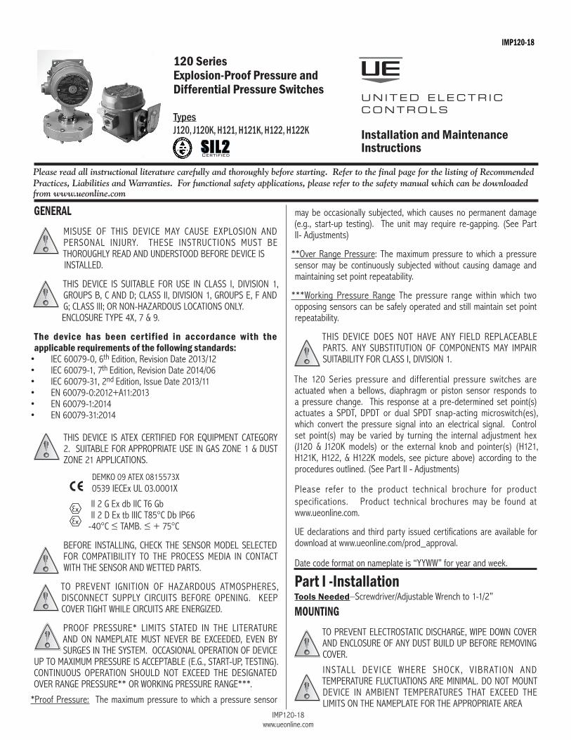
IMP120-18 www.ueonline.com 120 Series Explosion-Proof Pressure and Differential Pressure Switches Types J120, J120K, H121, H121K, H122, H122K UNITED ELECTRIC CONTROLS Installation and Maintenance Instructions IMP120-18 may be occasionally subjected, which causes no permanent damage (e.g., start-up testing). The unit may require re-gapping. (See Part II- Adjustments) **Over Range Pressure: The maximum pressure to which a pressure sensor may be continuously subjected without causing damage and maintaining set point repeatability. ***Working Pressure Range The pressure range within which two opposing sensors can be safely operated and still maintain set point repeatability. THIS DEVICE DOES NOT HAVE ANY FIELD REPLACEABLE PARTS. ANY SUBSTITUTION OF COMPONENTS MAY IMPAIR SUITABILITY FOR CLASS I, DIVISION 1. The 120 Series pressure and differential pressure switches are actuated when a bellows, diaphragm or piston sensor responds to a pressure change. This response at a pre-determined set point(s) actuates a SPDT, DPDT or dual SPDT snap-acting microswitch(es), which convert the pressure signal into an electrical signal. Control set point(s) may be varied by turning the internal adjustment hex (J120 & J120K models) or the external knob and pointer(s) (H121, H121K, H122, & H122K models, see picture above) according to the procedures outlined. (See Part II - Adjustments) Please refer to the product technical brochure for product specifications. Product technical brochures may be found at www.ueonline.com. UE declarations and third party issued certifications are available for download at www.ueonline.com/prod_approval. Date code format on nameplate is “YYWW” for year and week. Part I -Installation Tools Needed–Screwdriver/Adjustable Wrench to 1-1/2” MOUNTING TO PREVENT ELECTROSTATIC DISCHARGE, WIPE DOWN COVER AND ENCLOSURE OF ANY DUST BUILD UP BEFORE REMOVING COVER. INSTALL DEVICE WHERE SHOCK, VIBRATION AND TEMPERATURE FLUCTUATIONS ARE MINIMAL. DO NOT MOUNT DEVICE IN AMBIENT TEMPERATURES THAT EXCEED THE LIMITS ON THE NAMEPLATE FOR THE APPROPRIATE AREA GENERAL MISUSE OF THIS DEVICE MAY CAUSE EXPLOSION AND PERSONAL INJURY. THESE INSTRUCTIONS MUST BE THOROUGHLY READ AND UNDERSTOOD BEFORE DEVICE IS INSTALLED. THIS DEVICE IS SUITABLE FOR USE IN CLASS I, DIVISION 1, GROUPS B, C AND D; CLASS II, DIVISION 1, GROUPS E, F AND G; CLASS III; OR NON-HAZARDOUS LOCATIONS ONLY. ENCLOSURE TYPE 4X, 7 & 9. The device has been certified in accordance with the applicable requirements of the following standards: • IEC 60079-0, 6 th Edition, Revision Date 2013/12 • IEC 60079-1, 7 th Edition, Revision Date 2014/06 • IEC 60079-31, 2 nd Edition, Issue Date 2013/11 • EN 60079-0:2012+A11:2013 • EN 60079-1:2014 • EN 60079-31:2014 THIS DEVICE IS ATEX CERTIFIED FOR EQUIPMENT CATEGORY 2. SUITABLE FOR APPROPRIATE USE IN GAS ZONE 1 & DUST ZONE 21 APPLICATIONS. DEMKO 09 ATEX 0815573X 0539 IECEx UL 03.0001X II 2 G Ex db IIC T6 Gb II 2 D Ex tb IIIC T85°C Db IP66 -40°C ≤ Tamb. ≤ + 75°C BEFORE INSTALLING, CHECK THE SENSOR MODEL SELECTED FOR COMPATIBILITY TO THE PROCESS MEDIA IN CONTACT WITH THE SENSOR AND WETTED PARTS. TO PREVENT IGNITION OF HAZARDOUS ATMOSPHERES, DISCONNECT SUPPLY CIRCUITS BEFORE OPENING. KEEP COVER TIGHT WHILE CIRCUITS ARE ENERGIZED. PROOF PRESSURE* LIMITS STATED IN THE LITERATURE AND ON NAMEPLATE MUST NEVER BE EXCEEDED, EVEN BY SURGES IN THE SYSTEM. OCCASIONAL OPERATION OF DEVICE UP TO MAXIMUM PRESSURE IS ACCEPTABLE (E.G., START-UP, TESTING). CONTINUOUS OPERATION SHOULD NOT EXCEED THE DESIGNATED OVER RANGE PRESSURE** OR WORKING PRESSURE RANGE***. *Proof Pressure: The maximum pressure to which a pressure sensor Please read all instructional literature carefully and thoroughly before starting. Refer to the final page for the listing of Recommended Practices, Liabilities and Warranties. For functional safety applications, please refer to the safety manual which can be downloaded from www.ueonline.com SIL2 Certified
Transcript of Types J120, J120K, H121, H121K, H122, H122K Installation ... · IMP120-18 120 Series...
IMP120-18www.ueonline.com
120 SeriesExplosion-Proof Pressure andDifferential Pressure Switches TypesJ120, J120K, H121, H121K, H122, H122K
UNITED ELECTR IC CONTROLS
Installation and Maintenance Instructions
IMP120-18
may be occasionally subjected, which causes no permanent damage (e.g., start-up testing). The unit may require re-gapping. (See Part II- Adjustments)
**Over Range Pressure: The maximum pressure to which a pressure sensor may be continuously subjected without causing damage and maintaining set point repeatability.
***Working Pressure Range The pressure range within which two opposing sensors can be safely operated and still maintain set point repeatability.
ThIS devIce dOeS nOT hAve Any fIeld RePlAceAble PARTS. Any SubSTITuTIOn Of cOmPOnenTS mAy ImPAIR SuITAbIlITy fOR clASS I, dIvISIOn 1.
The 120 Series pressure and differential pressure switches are actuated when a bellows, diaphragm or piston sensor responds to a pressure change. This response at a pre-determined set point(s) actuates a SPdT, dPdT or dual SPdT snap-acting microswitch(es), which convert the pressure signal into an electrical signal. control set point(s) may be varied by turning the internal adjustment hex (J120 & J120K models) or the external knob and pointer(s) (h121, h121K, h122, & h122K models, see picture above) according to the procedures outlined. (See Part II - Adjustments)
Please refer to the product technical brochure for product specifications. Product technical brochures may be found at www.ueonline.com.
ue declarations and third party issued certifications are available for download at www.ueonline.com/prod_approval.
date code format on nameplate is “yyWW” for year and week.
Part I -InstallationTools Needed–Screwdriver/Adjustable Wrench to 1-1/2”
MOUNTINGTO PRevenT elecTROSTATIc dISchARge, WIPe dOWn cOveR And enclOSuRe Of Any duST buIld uP befORe RemOvIng cOveR.
InSTAll devIce WheRe ShOcK, vIbRATIOn And TemPeRATuRe flucTuATIOnS ARe mInImAl. dO nOT mOunT devIce In AmbIenT TemPeRATuReS ThAT exceed The lImITS On The nAmePlATe fOR The APPROPRIATe AReA
GENERALmISuSe Of ThIS devIce mAy cAuSe exPlOSIOn And PeRSOnAl InJuRy. TheSe InSTRucTIOnS muST be ThOROughly ReAd And undeRSTOOd befORe devIce IS
InSTAlled.
ThIS devIce IS SuITAble fOR uSe In clASS I, dIvISIOn 1, gROuPS b, c And d; clASS II, dIvISIOn 1, gROuPS e, f And g; clASS III; OR nOn-hAzARdOuS lOcATIOnS Only.
enclOSuRe TyPe 4x, 7 & 9.
The device has been certified in accordance with the applicable requirements of the following standards:• Iec 60079-0, 6th edition, Revision date 2013/12• Iec 60079-1, 7th edition, Revision date 2014/06• Iec 60079-31, 2nd edition, Issue date 2013/11• en 60079-0:2012+A11:2013• en 60079-1:2014• en 60079-31:2014
ThIS devIce IS ATex ceRTIfIed fOR equIPmenT cATegORy 2. SuITAble fOR APPROPRIATe uSe In gAS zOne 1 & duST zOne 21 APPlIcATIOnS.
demKO 09 ATex 0815573x 0539 Iecex ul 03.0001x
II 2 g ex db IIc T6 gb II 2 d ex tb IIIc T85°c db IP66 -40°C≤Tamb.≤+75°C
befORe InSTAllIng, checK The SenSOR mOdel SelecTed fOR cOmPATIbIlITy TO The PROceSS medIA In cOnTAcT WITh The SenSOR And WeTTed PARTS.
TO PRevenT IgnITIOn Of hAzARdOuS ATmOSPheReS, dIScOnnecT SuPPly cIRcuITS befORe OPenIng. KeeP cOveR TIghT WhIle cIRcuITS ARe eneRgIzed.
PROOf PReSSuRe* lImITS STATed In The lITeRATuRe And On nAmePlATe muST neveR be exceeded, even by SuRgeS In The SySTem. OccASIOnAl OPeRATIOn Of devIce
uP TO mAxImum PReSSuRe IS AccePTAble (e.g., START-uP, TeSTIng). cOnTInuOuS OPeRATIOn ShOuld nOT exceed The deSIgnATed OveR RAnge PReSSuRe** OR WORKIng PReSSuRe RAnge***.
*Proof Pressure: The maximum pressure to which a pressure sensor
Please read all instructional literature carefully and thoroughly before starting. Refer to the final page for the listing of Recommended Practices, Liabilities and Warranties. For functional safety applications, please refer to the safety manual which can be downloaded from www.ueonline.com
SIL2Certified
IMP120-18www.ueonline.com
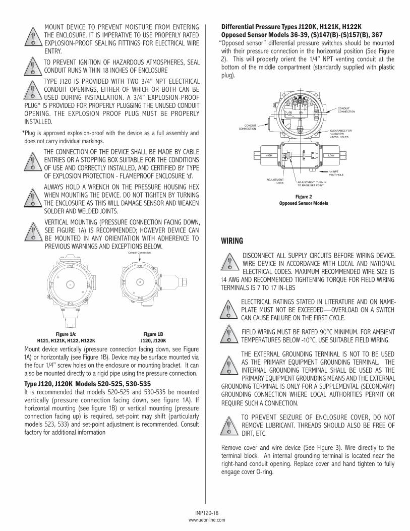
Differential Pressure Types J120K, H121K, H122K Opposed Sensor Models 36-39, (S)147(B)-(S)157(B), 367
“Opposed sensor” differential pressure switches should be mounted with their pressure connection in the horizontal position (See figure 2). This will properly orient the 1/4” nPT venting conduit at the bottom of the middle compartment (standardly supplied with plastic plug).
WIRINGdIScOnnecT All SuPPly cIRcuITS befORe WIRIng devIce. WIRe devIce In AccORdAnce WITh lOcAl And nATIOnAl elecTRIcAl cOdeS. mAxImum RecOmmended WIRe SIze IS
14 AWg And RecOmmended TIghTenIng TORque fOR fIeld WIRIng TeRmInAlS IS 7 TO 17 In-lbS
elecTRIcAl RATIngS STATed In lITeRATuRe And On nAme-PlATe muST nOT be exceeded—OveRlOAd On A SWITch cAn cAuSe fAIluRe On The fIRST cycle.
fIeld WIRIng muST be RATed 90°c mInImum. fOR AmbIenT TemPeRATuReS belOW -10°c, uSe SuITAble fIeld WIRIng.
The exTeRnAl gROundIng TeRmInAl IS nOT TO be uSed AS The PRImARy equIPmenT gROundIng TeRmInAl. The InTeRnAl gROundIng TeRmInAl ShAll be uSed AS The PRImARy equIPmenT gROundIng meAnS And The exTeRnAl
gROundIng TeRmInAl IS Only fOR A SuPPlemenTAl (SecOndARy) gROundIng cOnnecTIOn WheRe lOcAl AuThORITIeS PeRmIT OR RequIRe Such A cOnnecTIOn.
TO PRevenT SeIzuRe Of enclOSuRe cOveR, dO nOT RemOve lubRIcAnT. ThReAdS ShOuld AlSO be fRee Of dIRT, eTc.
Remove cover and wire device (See figure 3). Wire directly to the terminal block. An internal grounding terminal is located near the right-hand conduit opening. Replace cover and hand tighten to fully engage cover O-ring.
mOunT devIce TO PRevenT mOISTuRe fROm enTeRIng The enclOSuRe. IT IS ImPeRATIve TO uSe PROPeRly RATed exPlOSIOn-PROOf SeAlIng fITTIngS fOR elecTRIcAl WIRe enTRy.
TO PRevenT IgnITIOn Of hAzARdOuS ATmOSPheReS, SeAl cOnduIT RunS WIThIn 18 IncheS Of enclOSuRe
TyPe J120 IS PROvIded WITh TWO 3/4” nPT elecTRIcAl cOnduIT OPenIngS, eITheR Of WhIch OR bOTh cAn be uSed duRIng InSTAllATIOn. A 3/4” exPlOSIOn-PROOf
Plug* IS PROvIded fOR PROPeRly PluggIng The unuSed cOnduIT OPenIng. The exPlOSIOn PROOf Plug muST be PROPeRly InSTAlled.
*Plug is approved explosion-proof with the device as a full assembly and does not carry individual markings.
The cOnnecTIOn Of The devIce ShAll be mAde by cAble enTRIeS OR A STOPPIng bOx SuITAble fOR The cOndITIOnS Of uSe And cORRecTly InSTAlled, And ceRTIfIed by TyPe Of exPlOSIOn PROTecTIOn - flAmePROOf enclOSuRe ‘d’.
AlWAyS hOld A WRench On The PReSSuRe hOuSIng hex When mOunTIng The devIce. dO nOT TIghTen by TuRnIng The enclOSuRe AS ThIS WIll dAmAge SenSOR And WeAKen SOldeR And Welded JOInTS.
veRTIcAl mOunTIng (PReSSuRe cOnnecTIOn fAcIng dOWn, See fIguRe 1A) IS RecOmmended; hOWeveR devIce cAn be mOunTed In Any ORIenTATIOn WITh AdheRence TO PRevIOuS WARnIngS And excePTIOnS belOW.
mount device vertically (pressure connection facing down, see figure 1A) or horizontally (see figure 1b). device may be surface mounted via the four 1/4” screw holes on the enclosure or mounting bracket. It can also be mounted directly to a rigid pipe using the pressure connection.
Type J120, J120K Models 520-525, 530-535It is recommended that models 520-525 and 530-535 be mounted vertically (pressure connection facing down, see figure 1A). If horizontal mounting (see figure 1b) or vertical mounting (pressure connection facing up) is required, set-point may shift (particularly models 523, 533) and set-point adjustment is recommended. consult factory for additional information
Figure 2 Opposed Sensor Models
Figure 1BJ120, J120K
Figure 1A:H121, H121K, H122, H122K
IMP120-18www.ueonline.com
Part II - AdjustmentsTools Needed
Screwdriver5/8” Open end Wrench
5/64” Allen Wrench
AfTeR cOmPleTIng AdJuSTmenTS On TyPe h121 And h122, be SuRe TO Re-InSTAll AdJuSTmenT cOveR. dO nOT OveR TIghTen cOveR ScReWS.
for set point adjustment and re-gapping (if necessary), connect device to a calibrated pressure source.
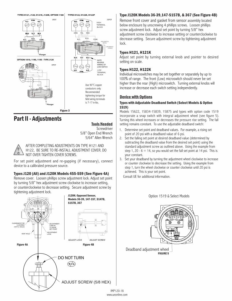
Types J120 (All) and J120K Models 455-559 (See Figure 4A)Remove cover. loosen phillips screw adjustment lock. Adjust set point by turning 5/8” hex adjustment screw clockwise to increase setting, or counterclockwise to decrease setting. Secure adjustment screw by tightening adjustment lock.
Type J120K Models 36-39,147-S157B, & 367 (See Figure 4B)Remove front cover and gasket from sensor assembly located below enclosure by unscrewing 4 phillips screws. loosen phillips screw adjustment lock. Adjust set point by turning 5/8” hex adjustment screw clockwise to increase setting or counterclockwise to decrease setting. Secure adjustment screw by tightening adjustment lock.
Types H121, H121KAdjust set point by turning external knob and pointer to desired setting on scale.
Types H122, H122KIndividual microswitches may be set together or separately by up to 100% of range. The front (low) microswitch should never be set higher than the rear (high) microswitch. Turning external knobs will increase or decrease each switch setting independently.
Device with OptionsTypes with Adjustable Deadband Switch (Select Models & Option 1519)models 15622, 15834-15839, 15875 and types with option code 1519 incorporate a snap switch with integral adjustment wheel (see figure 5). Turning this wheel increases or decreases the pressure rise setting. The fall setting remains constant. To use the adjustable deadband switch:
1. determine set point and deadband values. for example, a rising set point of 20 psi with a deadband value of 6 psi.
2. Set the falling set point at desired deadband value (determined by subtracting the deadband value from the desired set point) using the standard adjustment screw as outlined above. using the example from step 1, 20 - 6 = 14, so you would set the fall set point at 14 psi. This is your constant.
3. Set your deadband by turning the adjustment wheel clockwise to increase or counter clockwise to decrease the setting. using the example from step 1, turn the wheel clockwise or counter clockwise until 20 psi is achieved. This is your set point.
consult ue for additional information.
Option 1519 & Select models J120K: Opposed Sensor, Models 36-39, 147-157, S147B, S157B, 367
Figure 3
use 90°c copper conductors only. Recommended tightening torque for field wiring terminals is 7-17 in-lbs.
Figure 4BFigure 4A
DO NOT TURN
deadband adjustment wheelFIGURE 5
N.C. N.O. COM.
Plunger
ORN YEL RED
N.C.1
N.C.2
N.O.1
N.O.2COM. 1
COM. 2
Plunger
RED
YEL.
ORN.
TYPES H121, J120, H121K, J120K, OPTION 1180 TYPES H122, H122K, H122P
OPTION 1010, 1190, 1195 - TYPE J120BLUVLTBLK
NOTE REVERSE WIRING OF LOW SWITCH
N.C. N.O. COM.
N.C. N.O. COM.
DPDT
SPDT 2SPDT
IMP120-18www.ueonline.com
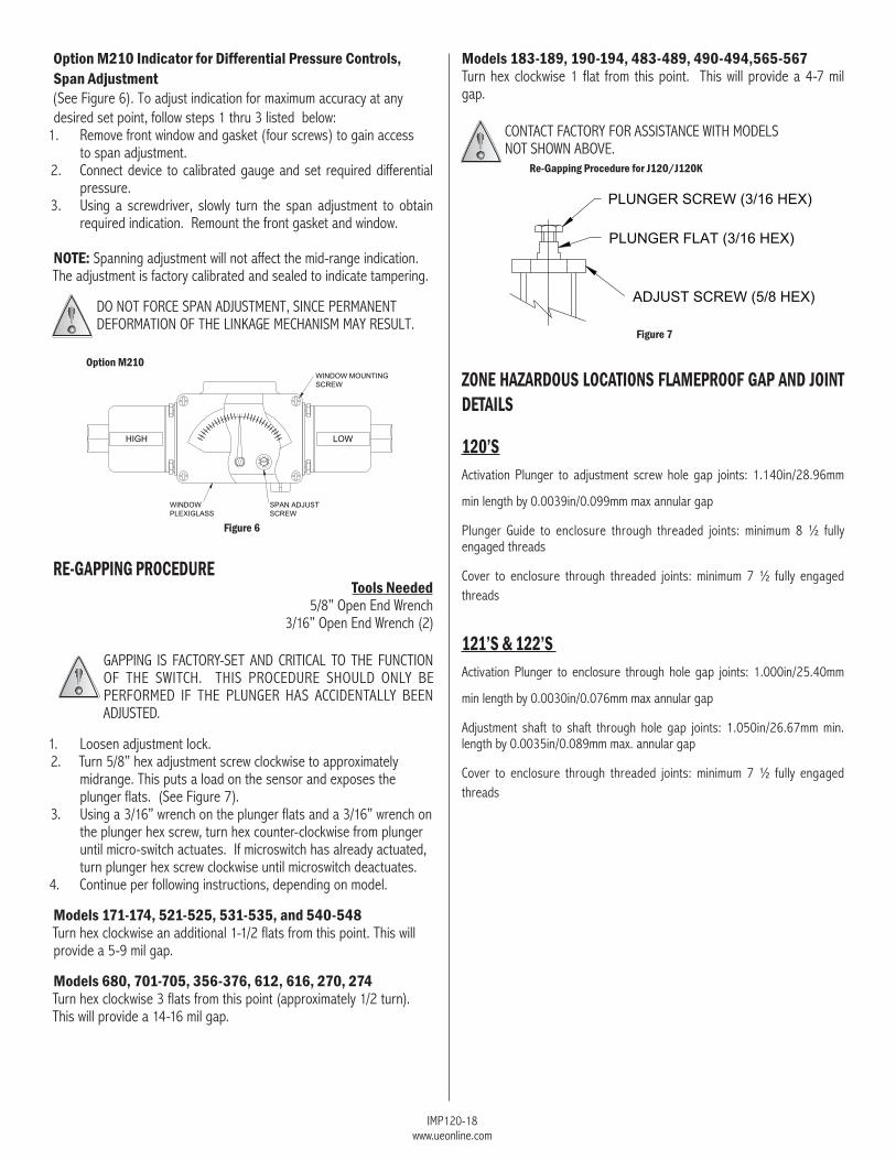
Option M210 Indicator for Differential Pressure Controls,Span Adjustment(See figure 6). To adjust indication for maximum accuracy at any desired set point, follow steps 1 thru 3 listed below:
1. Remove front window and gasket (four screws) to gain access to span adjustment.
2. connect device to calibrated gauge and set required differential pressure.
3. using a screwdriver, slowly turn the span adjustment to obtain required indication. Remount the front gasket and window.
NOTE: Spanning adjustment will not affect the mid-range indication. The adjustment is factory calibrated and sealed to indicate tampering.
dO nOT fORce SPAn AdJuSTmenT, SInce PeRmAnenT defORmATIOn Of The lInKAge mechAnISm mAy ReSulT.
RE-GAPPING PROCEDURE Tools Needed
5/8” Open end Wrench3/16” Open end Wrench (2)
gAPPIng IS fAcTORy-SeT And cRITIcAl TO The funcTIOn Of The SWITch. ThIS PROceduRe ShOuld Only be PeRfORmed If The PlungeR hAS AccIdenTAlly been AdJuSTed.
1. loosen adjustment lock.2. Turn 5/8” hex adjustment screw clockwise to approximately
midrange. This puts a load on the sensor and exposes the plunger flats. (See figure 7).
3. using a 3/16” wrench on the plunger flats and a 3/16” wrench on the plunger hex screw, turn hex counter-clockwise from plunger until micro-switch actuates. If microswitch has already actuated, turn plunger hex screw clockwise until microswitch deactuates.
4. continue per following instructions, depending on model.
Models 171-174, 521-525, 531-535, and 540-548Turn hex clockwise an additional 1-1/2 flats from this point. This will provide a 5-9 mil gap.
Models 680, 701-705, 356-376, 612, 616, 270, 274Turn hex clockwise 3 flats from this point (approximately 1/2 turn). This will provide a 14-16 mil gap.
Re-Gapping Procedure for J120/J120K
Figure 7
Models 183-189, 190-194, 483-489, 490-494,565-567Turn hex clockwise 1 flat from this point. This will provide a 4-7 mil gap.
cOnTAcT fAcTORy fOR ASSISTAnce WITh mOdelS nOT ShOWn AbOve.
zONE HAzARDOUS LOCATIONS FLAMEPROOF GAP AND JOINT DETAILS
120’SActivation Plunger to adjustment screw hole gap joints: 1.140in/28.96mm
min length by 0.0039in/0.099mm max annular gap
Plunger guide to enclosure through threaded joints: minimum 8 ½ fully engaged threads
cover to enclosure through threaded joints: minimum 7 ½ fully engaged threads
121’S & 122’S Activation Plunger to enclosure through hole gap joints: 1.000in/25.40mm
min length by 0.0030in/0.076mm max annular gap
Adjustment shaft to shaft through hole gap joints: 1.050in/26.67mm min. length by 0.0035in/0.089mm max. annular gap
cover to enclosure through threaded joints: minimum 7 ½ fully engaged threads
Figure 6
Option M210
IMP120-18www.ueonline.com
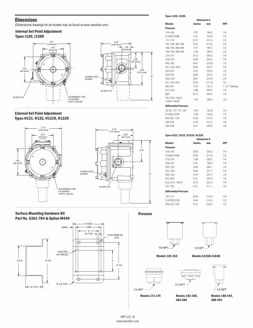
Internal Set Point AdjustmentTypes J120, J120K
External Set Point AdjustmentTypes H121, H122, H121K, H122K
Models 126-164 Models S126B-S164B
Models 171-174 Models 188-194, 488-494
Models 183-186, 483-486
PressureSurface Mounting Hardware KitPart No. 6361-704 & Option M449
Types J120, J120KDimension A
Models Inches mm NPTPressure126-164 7.25 184.2 1/4S126b-S164b 7.63 193.8 1/2171-174 8.72 221.5 1/2183-186, 483-486 8.41 213.6 1/2188-189, 488-489 7.47 189.7 1/2190-194, 490-494 7.44 189.0 1/2270-274 8.13 206.5 1/4358-376 8.09 205.5 1/4450, 452 8.81 223.8 1/4451, 453, 454 8.06 204.7 1/4520-525 9.25 235.0 1/2530-535 8.84 224.5 1/2550, 552 8.81 223.8 1/4551, 553-555 8.34 211.8 1/4565-567 7.53 191.3 1-1/2” Sanitary612, 616 7.88 200.2 1/4680 8.13 206.5 1/4701-705, 15622, 15834-15839
7.44 189.0 1/4
Differential Pressure36-39, 147-157, 367 7.59 192.8 1/4S147b-S157b 7.59 192.8 1/2455-457, 559 8.44 214.4 1/4540-543 9.34 237.2 1/8544-548 9.41 239.0 1/8
Types H121, H122, H121K, H122KDimension A
Models Inches mm NPTPressure126-164 8.09 205.5 1/4S126b-S164b 8.50 215.9 1/2270-274 7.88 200.2 1/4358-376 7.81 198.4 1/4450, 452 9.69 246.1 1/4453, 454 8.94 227.1 1/4550, 552 9.75 247.7 1/4553-555 9.31 236.5 1/4612, 614, 15875 8.75 222.3 1/4701-705 8.31 211.1 1/4
Differential Pressure
147-157 8.44 214.4 1/4S147b-S157b 8.44 214.4 1/2456-457, 559 9.31 236.5 1/4
Dimensions(Dimensional drawings for all models may be found at www.ueonline.com)
IMP120-18www.ueonline.com
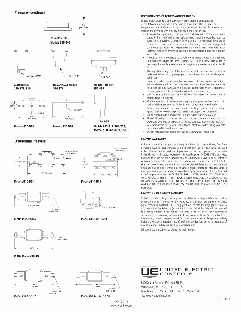
Models 612-616, 701-705,15622, 15834-15839, 15875
Models S147B & S157BModels 147 & 157
J120K Models 36-39
Models 530-535
Models 540-543
J120K Models 367 Models 455-457, 559
Models 544-548
Models 520-525
J120 Models270-376, 680
H121/H122 Models 270-376
Models 450-454, 550-555
Differential Pressure
Models 565-567
cP121110K
RECOMMENDED PRACTICES AND WARNINGS
United Electric Controls Company recommends careful consideration of the following factors when specifying and installing UE pressure and temperature units. Before installing a unit, the Installation and Maintenance instructions provided with unit must be read and understood.
• To avoid damaging unit, proof pressure and maximum temperature limits stated in literature and on nameplates must never be exceeded, even by surges in the system. Operation of the unit up to maximum pressure or temperature is acceptable on a limited basis (e.g., start-up, testing) but continuous operation must be restricted to the designated adjustable range. Excessive cycling at maximum pressure or temperature limits could reduce sensor life.
• A back-up unit is necessary for applications where damage to a primary unit could endanger life, limb or property. A high or low limit switch is necessary for applications where a dangerous runaway condition could result.
• The adjustable range must be selected so that incorrect, inadvertent or malicious setting at any range point cannot result in an unsafe system condition.
• Install unit where shock, vibration and ambient temperature fluctuations will not damage unit or affect operation. Orient unit so that moisture does not enter the enclosure via the electrical connection. When appropriate, this entry point should be sealed to prevent moisture entry.
• Unit must not be altered or modified after shipment. Consult UE if modification is necessary.
• Monitor operation to observe warning signs of possible damage to unit, such as drift in set point or faulty display. Check unit immediately.
• Preventative maintenance and periodic testing is necessary for critical applications where damage could endanger property or personnel.
• For all applications, a factory set unit should be tested before use.• Electrical ratings stated in literature and on nameplate must not be
exceeded. Overload on a switch can cause damage, even on the first cycle. Wire unit according to local and national electrical codes, using wire size recommended in installation sheet.
• Do not mount unit in ambient temp. exceeding published limits.
LIMITED WARRANTY
Seller warrants that the product hereby purchased is, upon delivery, free from defects in material and workmanship and that any such product which is found to be defective in such workmanship or material will be repaired or replaced by Seller (Ex-works, Factory, Watertown, Massachusetts. INCOTERMS); provided, however, that this warranty applies only to equipment found to be so defective within a period of 24 months from the date of manufacture by the Seller. Seller shall not be obligated under this warranty for alleged defects which examination discloses are due to tampering, misuse, neglect, improper storage, and in any case where products are disassembled by anyone other than authorized Seller’s representatives. EXCEPT FOR THE LIMITED WARRANTY OF REPAIR AND REPLACEMENT STATED ABOVE, SELLER DISCLAIMS ALL WARRANTIES WHATSOEVER WITH RESPECT TO THE PRODUCT, INCLUDING ALL IMPLIED WARRANTIES OF MERCHANTABILITY OR FITNESS FOR ANY PARTICULAR PURPOSE.
LIMITATION OF SELLER’S LIAbILITY
Seller’s liability to Buyer for any loss or claim, including liability incurred in connection with (i) breach of any warranty whatsoever, expressed or implied, (ii) a breach of contract, (iii) a negligent act or acts (or negligent failure to act) committed by Seller, or (iv) an act for which strict liability will be inputted to seller, is limited to the “limited warranty” of repair and/or replacement as so stated in our warranty of product. In no event shall the Seller be liable for any special, indirect, consequential or other damages of a like general nature, including, without limitation, loss of profits or production, or loss or expenses of any nature incurred by the buyer or any third party.
UE specifications subject to change without notice.
180 dexter Avenue, P.O. box 9143Watertown, mA 02471-9143 uSATelephone: 617 926-1000 fax: 617 926-2568http://www.ueonline.com
Pressure - continued