ITS WC Challenges of Platooning Concept and Modelling
12
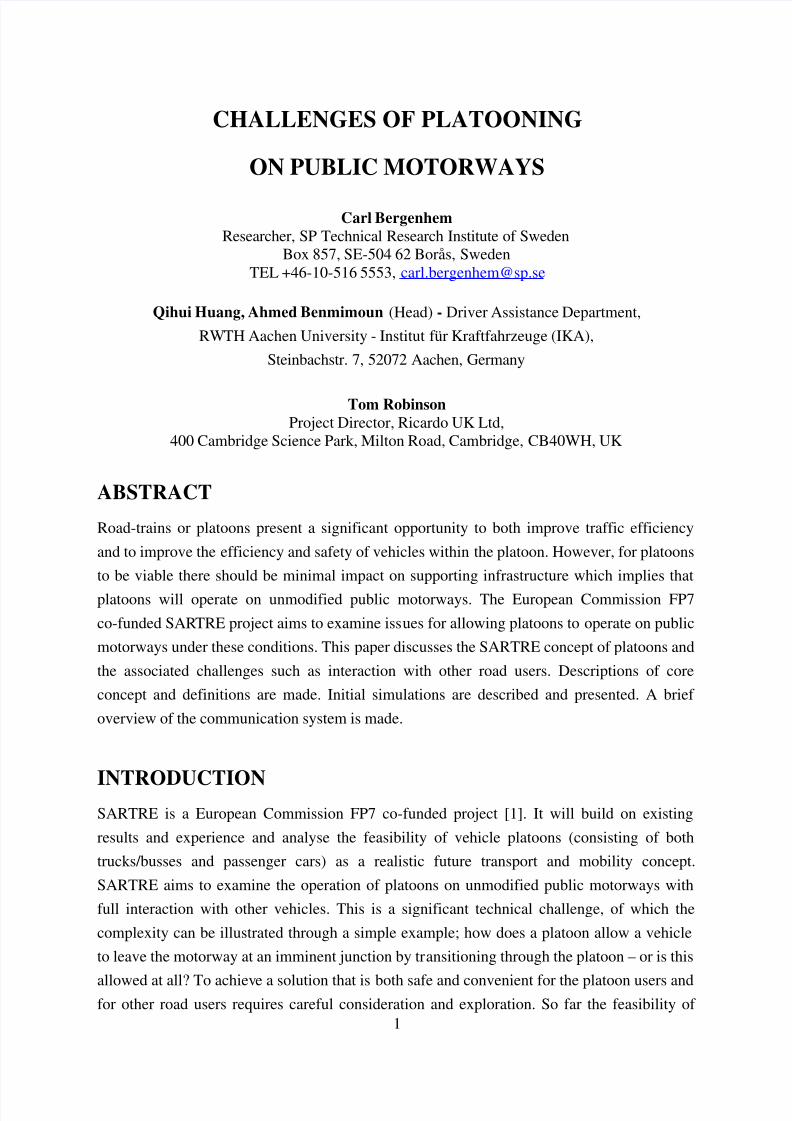
1 CHALLENGES OF PLATOONING ON PUBLIC MOTORWAYS Carl Bergenhem Researcher, SP Technical Research Institute of Sweden Box 857, SE-504 62 Borås, Sweden TEL +46-10-516 5553, [email protected] Qihui Huang, Ahmed Benmimoun (Head) - Driver Assistance Department, RWTH Aachen University - Institut für Kraftfahrzeuge (IKA), Steinbachstr. 7, 52072 Aachen, Germany Tom Robinson Project Director, Ricardo UK Ltd, 400 Cambridge Science Park, Milton Road, Cambridge, CB40WH, UK ABSTRACT Road-trains or platoons present a significant opportunity to both improve traffic efficiency and to improve the efficiency and safety of vehicles within the platoon. However, for platoons to be viable there should be minimal impact on supporting infrastructure which implies that platoons will operate on unmodified public motorways. The European Commission FP7 co-funded SAR TRE project aims to examine iss ues for allowing platoons to operate on public motorways under these conditions. This paper discusses the SARTRE concept of platoons and the associated challenges such as interaction with other road users. Descriptions of core concept and definitions are made. Initial simulations are described and presented. A brief overview of the communication system is made. INTRODUCTION SARTRE is a European Commission FP7 co-funded project [1]. It will build on existing results and experience and analyse the feasibility of vehicle platoons (consisting of both trucks/busses and passenger cars) as a realistic future transport and mobility concept. SARTRE aims to examine the operation of platoons on unmodified public motorways with full interaction with other vehicles. This is a significant technical challenge, of which the complexity can be illustrated through a simple example; how does a platoon allow a vehicle to leave the motorway at an imminent junction by tr ansitioning through the platoon – or is this allowed at all? To achieve a solution that is both safe and convenient for the platoon users and for other road users requires careful consideration and exploration. So far the feasibility of
-
Upload
david-herron -
Category
Documents
-
view
221 -
download
0
Transcript of ITS WC Challenges of Platooning Concept and Modelling
8/3/2019 ITS WC Challenges of Platooning Concept and Modelling
http://slidepdf.com/reader/full/its-wc-challenges-of-platooning-concept-and-modelling 1/12
1
CHALLENGES OF PLATOONING
ON PUBLIC MOTORWAYS
Carl Bergenhem Researcher, SP Technical Research Institute of Sweden
Box 857, SE-504 62 Borås, SwedenTEL +46-10-516 5553, [email protected]
Qihui Huang, Ahmed Benmimoun (Head) - Driver Assistance Department,
RWTH Aachen University - Institut für Kraftfahrzeuge (IKA),
Steinbachstr. 7, 52072 Aachen, Germany
Tom Robinson Project Director, Ricardo UK Ltd,
400 Cambridge Science Park, Milton Road, Cambridge, CB40WH, UK
ABSTRACT
Road-trains or platoons present a significant opportunity to both improve traffic efficiency
and to improve the efficiency and safety of vehicles within the platoon. However, for platoons
to be viable there should be minimal impact on supporting infrastructure which implies that
platoons will operate on unmodified public motorways. The European Commission FP7
co-funded SARTRE project aims to examine issues for allowing platoons to operate on public
motorways under these conditions. This paper discusses the SARTRE concept of platoons and
the associated challenges such as interaction with other road users. Descriptions of core
concept and definitions are made. Initial simulations are described and presented. A brief
overview of the communication system is made.
INTRODUCTIONSARTRE is a European Commission FP7 co-funded project [1]. It will build on existing
results and experience and analyse the feasibility of vehicle platoons (consisting of both
trucks/busses and passenger cars) as a realistic future transport and mobility concept.
SARTRE aims to examine the operation of platoons on unmodified public motorways with
full interaction with other vehicles. This is a significant technical challenge, of which the
complexity can be illustrated through a simple example; how does a platoon allow a vehicle
to leave the motorway at an imminent junction by transitioning through the platoon – or is this
allowed at all? To achieve a solution that is both safe and convenient for the platoon users andfor other road users requires careful consideration and exploration. So far the feasibility of
8/3/2019 ITS WC Challenges of Platooning Concept and Modelling
http://slidepdf.com/reader/full/its-wc-challenges-of-platooning-concept-and-modelling 2/12
2
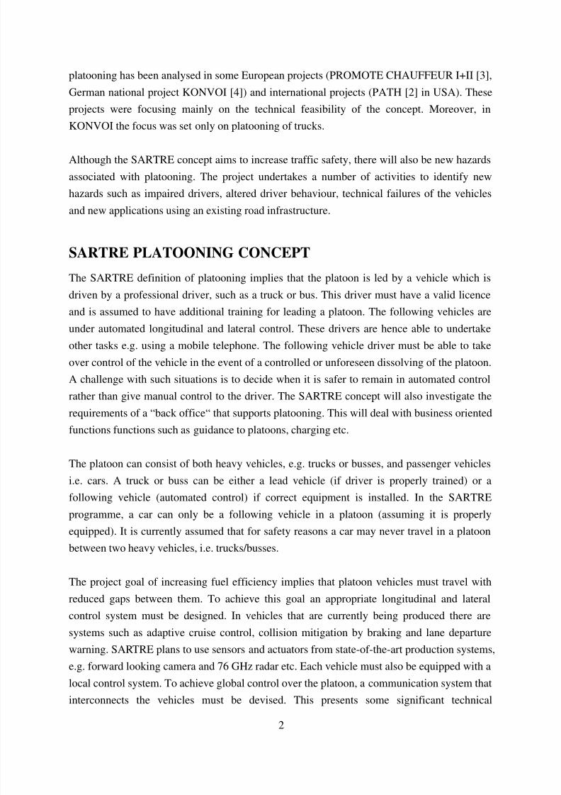
platooning has been analysed in some European projects (PROMOTE CHAUFFEUR I+II [3],
German national project KONVOI [4]) and international projects (PATH [2] in USA). These
projects were focusing mainly on the technical feasibility of the concept. Moreover, in
KONVOI the focus was set only on platooning of trucks.
Although the SARTRE concept aims to increase traffic safety, there will also be new hazards
associated with platooning. The project undertakes a number of activities to identify new
hazards such as impaired drivers, altered driver behaviour, technical failures of the vehicles
and new applications using an existing road infrastructure.
SARTRE PLATOONING CONCEPT
The SARTRE definition of platooning implies that the platoon is led by a vehicle which isdriven by a professional driver, such as a truck or bus. This driver must have a valid licence
and is assumed to have additional training for leading a platoon. The following vehicles are
under automated longitudinal and lateral control. These drivers are hence able to undertake
other tasks e.g. using a mobile telephone. The following vehicle driver must be able to take
over control of the vehicle in the event of a controlled or unforeseen dissolving of the platoon.
A challenge with such situations is to decide when it is safer to remain in automated control
rather than give manual control to the driver. The SARTRE concept will also investigate the
requirements of a “back office“ that supports platooning. This will deal with business orientedfunctions functions such as guidance to platoons, charging etc.
The platoon can consist of both heavy vehicles, e.g. trucks or busses, and passenger vehicles
i.e. cars. A truck or buss can be either a lead vehicle (if driver is properly trained) or a
following vehicle (automated control) if correct equipment is installed. In the SARTRE
programme, a car can only be a following vehicle in a platoon (assuming it is properly
equipped). It is currently assumed that for safety reasons a car may never travel in a platoon
between two heavy vehicles, i.e. trucks/busses.
The project goal of increasing fuel efficiency implies that platoon vehicles must travel with
reduced gaps between them. To achieve this goal an appropriate longitudinal and lateral
control system must be designed. In vehicles that are currently being produced there are
systems such as adaptive cruise control, collision mitigation by braking and lane departure
warning. SARTRE plans to use sensors and actuators from state-of-the-art production systems,
e.g. forward looking camera and 76 GHz radar etc. Each vehicle must also be equipped with a
local control system. To achieve global control over the platoon, a communication system that
interconnects the vehicles must be devised. This presents some significant technical

8/3/2019 ITS WC Challenges of Platooning Concept and Modelling
http://slidepdf.com/reader/full/its-wc-challenges-of-platooning-concept-and-modelling 3/12
3
challenges when the safety requirements are considered and is likely to require a backup
communications mechanism. The control strategy for the platoon will be a combination of
local control where each vehicle individually senses its environment and global control where
the lead vehicle decides set-points e.g. following distance and speed. Global control may also
be required to avoid oscillations in the platoon as these will have a detrimental effect on fuelefficiency, safety and also passenger comfort.
DEFINITIONS FOR PLATOONING
This section describes some of the definitions that have been made in SARTRE. The
platooning concept contains a set of combined use cases and procedures which describe the
complete concept including how to join, maintain and dissolve platoons. The concept also
contains definitions of driver vehicle interaction, terminology, prerequisites and assumptions.The definitions in Table 1 have been made for platooning.
Table 1: Definitions for platooning
Concept Description
Autonomous driving Both lateral and longitudinal autonomous control. The technical equipment controls the vehicle without
driver involvement. This is only possible for an FV.
BO (Back office) Back office is an infrastructure unit that supports the back office administrator. BO also covers toll booths.
BUC (Back office Use Case) Back office Use Case concerns services for making platooning economically feasible, hire charging andguiding vehicle to suitable platoon
FV (Following Vehicle) A vehicle, truck, bus or car, in a platoon behind an LV. FV is controlled without driver involvement while in
the platoon
LV (Lead Vehicle) LV is the lead vehicle of a platoon and is a truck or bus. LV is controlled by a driver.
OV (Other Vehicle) A vehicle that will never join a platoon but may affect it.
PFV (Potential Following
Vehicle)
A PFV is not currently platooning, but may do so. When in a platoon this vehicle is an FV.
Platoon A platoon is a number of vehicles that are travelling together and electronically connected (e.g. via wireless
communication). There is one LV and one or more FVs. The FV(s) of a platoon are controlled autonomously
while the LV is controlled manually.
PLV (Potential Lead Vehicle) A PLV is not currently leading a platoon, but may do so. A PLV in a platoon becomes LV.
PPV (Potential Platoon
Vehicle)
A vehicle that may be included in a platoon. PPV is controlled manually. A PPV in a platoon is either an FV
or LV
PUC (Platoon Use Case) A UC concerning the behaviour of a platoon.
PV (Platoon Vehicle) An LV or FV. In the case of FV it is controlled autonomously.
System A system is here a logical grouping of platoon and Back office Use Cases containing the overall required
behaviour.
8/3/2019 ITS WC Challenges of Platooning Concept and Modelling
http://slidepdf.com/reader/full/its-wc-challenges-of-platooning-concept-and-modelling 4/12
4
USE CASES
A Use Case is a form of requirement specification that describes an interaction between one
or more actors and a system to accomplish a goal. The SARTRE Use Cases are divided into
Platoon Use Cases (PUCs) and Back office Use Cases (BUCs). PUCs relate to the structure of the platoon and its primary operation. BUCs relate to infrastructure issues such as charging,
navigating to a platoon etc.
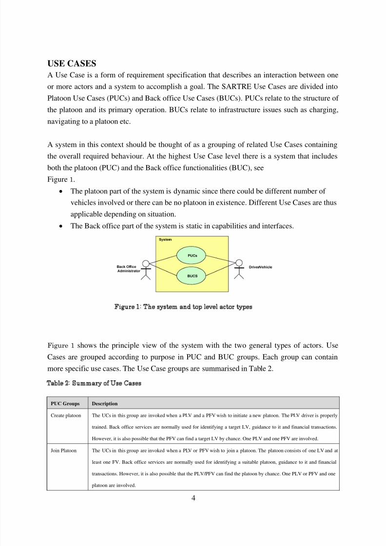
A system in this context should be thought of as a grouping of related Use Cases containing
the overall required behaviour. At the highest Use Case level there is a system that includes
both the platoon (PUC) and the Back office functionalities (BUC), see
Figure 1.
• The platoon part of the system is dynamic since there could be different number of vehicles involved or there can be no platoon in existence. Different Use Cases are thus
applicable depending on situation.
• The Back office part of the system is static in capabilities and interfaces.
Figure 1 shows the principle view of the system with the two general types of actors. Use
Cases are grouped according to purpose in PUC and BUC groups. Each group can contain
more specific use cases. The Use Case groups are summarised in Table 2.
Table 2: Summary of Use Cases
PUC Groups Description
Create platoon The UCs in this group are invoked when a PLV and a PFV wish to initiate a new platoon. The PLV driver is properly
trained. Back office services are normally used for identifying a target LV, guidance to it and financial transactions.
However, it is also possible that the PFV can find a target LV by chance. One PLV and one PFV are involved.
Join Platoon The UCs in this group are invoked when a PLV or PFV wish to join a platoon. The platoon consists of one LV and at
least one FV. Back office services are normally used for identifying a suitable platoon, guidance to it and financial
transactions. However, it is also possible that the PLV/PFV can find the platoon by chance. One PLV or PFV and one
platoon are involved.
Figure 1: The system and top level actor types
8/3/2019 ITS WC Challenges of Platooning Concept and Modelling
http://slidepdf.com/reader/full/its-wc-challenges-of-platooning-concept-and-modelling 5/12
5
Maintain
platoon
The UCs in this group are invoked when speed, longitudinal or lateral position of one or more FVs have to be
adjusted and when an LV or FV wants to continue in the platoon longer than initially decided. One platoon is involved
with its LV and FV(s).
Leave Platoon The UCs in this group are invoked when an LV or FV wishes to leave the platoon it is currently part of. A leaving FV
becomes a PFV and a leaving LV becomes a PLV thus under manual control. The platoon still exists after the LV or
FV has left. One platoon and one FV of the platoon are involved. In the case of the LV leaving there must exist a PLV
that can “take over” otherwise the platoon is dissolved.
Dissolve
platoon
The UCs in this group are invoked in the following cases:
• when an LV wants to leave the platoon in a controlled manner
• when an FV wants to leave the platoon with only two members in a controlled manner.
• when there are too many OVs within the platoon. Note that OVs can never participate in platooning
• when there is an emergency
After dissolution of the platoon, the LV and FV(s) become PLV and PFV(s) respectively and will thus be under
manual control.
BUC Groups Description
Register The UCs in this group are relevant for a vehicle interested in becoming a member of a platoon. The following
functionality is supported:
• To register information, e.g. platoon is created, number and type of vehicles, destination
• To check if truck/bus driver is platoon trained.
Handle platoon
status
The UCs in this group are invoked when platoon status has changed and Back office needs to be informed. Examples
of change includes platoon dissolution, FV or LV leave and emergency situations
Charge platoon The UCs in this group are invoked when financial transactions (payment and crediting) shall be made. Principles for
financial transactions are not specified. It could be handled in advance, partial or full, or afterwards. An example of
functionality is FV payment to LV via the BO.
Guide to
platoon
The UCs in this group are invoked when road guidance is needed. The following functionality is supported:
• Find target PLV - PFV and give guidance information to PFV driver how to find PLV.
• Find target platoon - PFV and give guidance information to PFV driver how to find the platoon.
MODELLING PLATOON STRATEGY
In a first step the SARTRE concept is refined and analysed in detail by means of virtual
implementation using the simulation tool PELOPS. The use cases are implemented with
corresponding simulation scenarios. These simulations are used to further refine the
platooning concept. For example a join manoeuvre may occur in different ways; from the rear,
side or front with several different control strategies being used. These approaches are
implemented in simulation and compared with respect to performance and efficiency.
Simulations also help to identify system requirements and limitations. Requirements are
8/3/2019 ITS WC Challenges of Platooning Concept and Modelling
http://slidepdf.com/reader/full/its-wc-challenges-of-platooning-concept-and-modelling 6/12
6
related to platoon modules like e.g. sensors (communication range and latency, accuracy etc.).
Simulations based on the defined concept and high level requirements help platoon limitations
to be derived (e.g. maximum number of platoon vehicles to avoid string instability).
OVERVIEW OF PELOPS
PELOPS (Program for the DEvelopment of LOngitudinal Traffic Processes in System
Relevant Environment) is a (sub)-microscopic traffic model and represents a combination of a
detailed sub-microscopic vehicle model and a microscopic traffic model. This allows for the
analytical investigation of the vehicle longitudinal dynamic behaviour as well as the traffic
flow. The advantage of this method is to consider all interactions that take place between the
driver, vehicle and traffic.
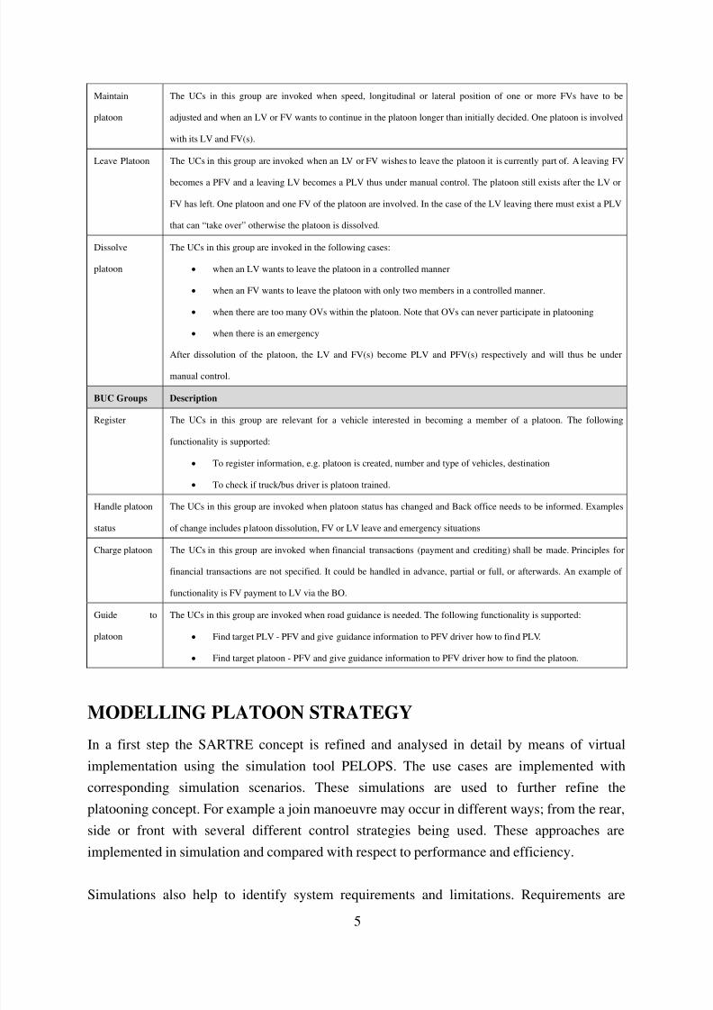
PELOPS [7] has been developed in cooperation with BMW within PROMETHEUS [8] andhas been enhanced continuously since 1989. Contrary to classical simulation tools in the
automotive industry, which represent only a part system or single isolated vehicle, the core of
PELOPS comprises the three significant elements of the traffic system - track/environment,
driver and vehicle - and their interactions. These three elements are modelled in a modular
program structure and defined by interfaces, see Figure 2.
Figure 2: PELOPS structure
PLATOONING IN PELOPS
In order to allow the simulation of platoons according to the defined use cases and SARTRE
concepts the models in PELOPS have been enhanced. The enhancements of PELOPS have
been made under consideration of the experience gained in previous projects, in particular the
German national project KONVOI [4]. A generic platoon control, which can take over the
longitudinal and lateral control of the vehicle in case of autonomous driving, can now be
“build in” in the vehicle. The technical equipment controls the vehicle without driver
involvement. This situation can only occur for a following vehicle. The lead vehicle is always
8/3/2019 ITS WC Challenges of Platooning Concept and Modelling
http://slidepdf.com/reader/full/its-wc-challenges-of-platooning-concept-and-modelling 7/12
7
controlled manually by the PELOPS driver. The platoon control is a dynamic link library
(DLL) that is loaded at runtime. Every vehicle in a PELOPS simulation scenario can be
equipped with a platoon control.
In order to simulate the HMI in the real vehicle, a virtual HMI manager has been developed.It manages the information to and from the driver like requests (e.g. leave, join, etc.),
acknowledgements (e.g. dissolve, leave, join, etc), cancel (joining, leaving) or discard joining.
Furthermore, the HMI manager computes the platoon status and provides information to the
driver and to the platoon control. The data exchange between PELOPS and the virtual HMI
manager is realised by means of an Ethernet connection using broadcasting method. With help
of a graphical user interface messages can be sent. Furthermore, this graphical user interface
displays information (position, velocity, distance to vehicle ahead, platoon status, etc.) of the
specified (potential) platoon vehicle.
Besides using a vehicle model of PELOPS database, external vehicle models (e.g.
MATLAB/Simulink models of VCC and VTEC) can be taken into consideration in PELOPS
by means of the Ethernet based data exchange as well. A common interface has been
elaborated in cooperation with the project partners. This interface to MATLAB/Simulink
vehicle models enables both the inputs from a driver in case of manual mode and the inputs of
the platoon control in case of autonomous mode.
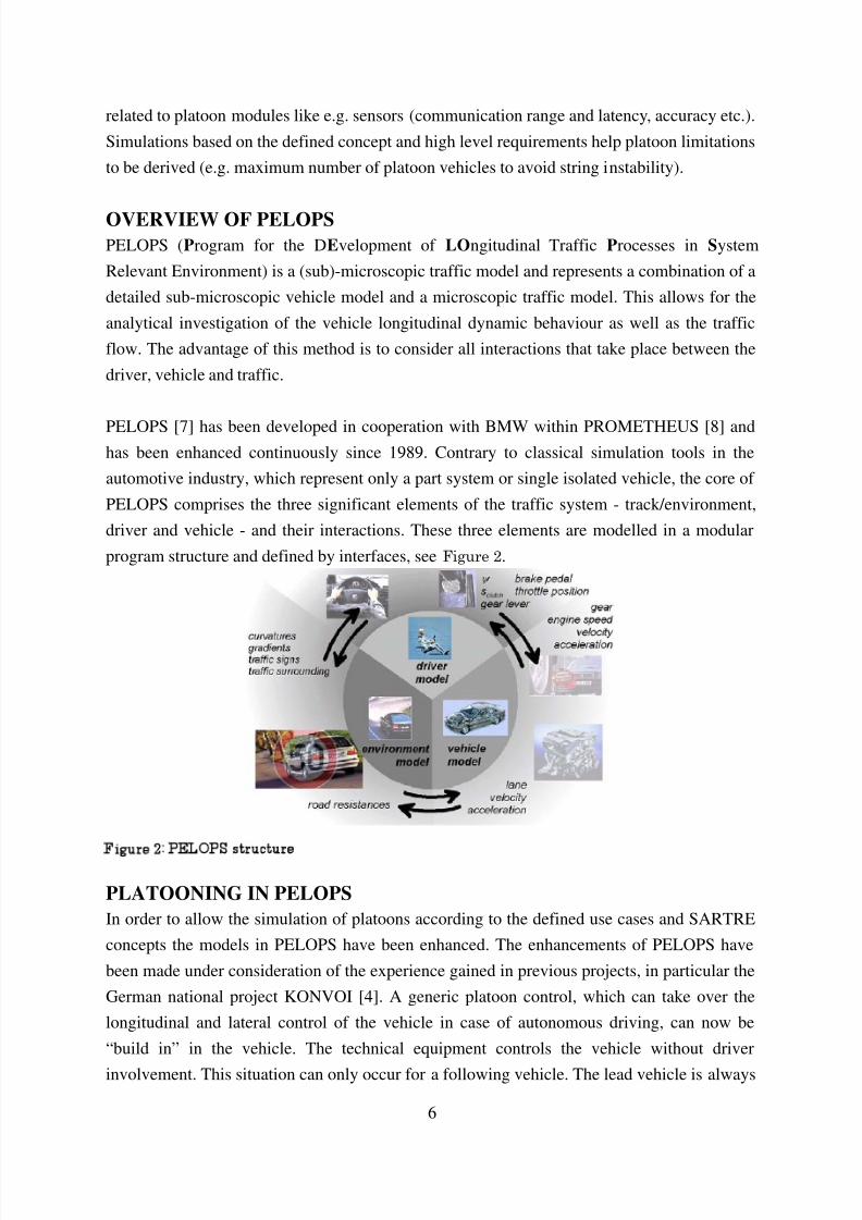
Furthermore, in order to visualize the traffic simulation during runtime, PELOPS can be
coupled to a visualization software by means of the above described broadcast-messaging. In
summary Figure 3 illustrates the simulation environment for analysis of platoon concepts.
Figure 3: PELOPS simulation environment for platooning
8/3/2019 ITS WC Challenges of Platooning Concept and Modelling
http://slidepdf.com/reader/full/its-wc-challenges-of-platooning-concept-and-modelling 8/12
8
In addition the implementation of the above described systems and vehicle models, PELOPS'
driver model has been adapted too. This modification concerns the driver-vehicle (system)
interaction, so that the possibility is given to keep the driver in the loop (for monitoring and
overriding the system), if needed. The transition from manual to autonomous driving and
vice-versa is of particular importance.
SIMULATION RESULTS
Based on the defined use cases and concepts, several simulation scenarios have been
generated to analyze the SARTRE platooning concept. Important aspects like the proper gap
size for joining and leaving, the time needed for creating, joining or leaving a platoon, string
stability, the influence on the traffic flow, e.g. at highway entrances and exits and fuel
consumption etc. can be investigated. Some of the simulation results are presented in this
chapter.
In the first step, the following Use Cases have been simulated in different scenarios; based on
use cases. The type of vehicles and desired platooning gap size was varied:
• Create Platoon
• Dissolve Platoon
• Join Platoon from 1) rear, 2) side and 3) front
• Leave Platoon from 1) side and 2) front
•
Maintain Platoon
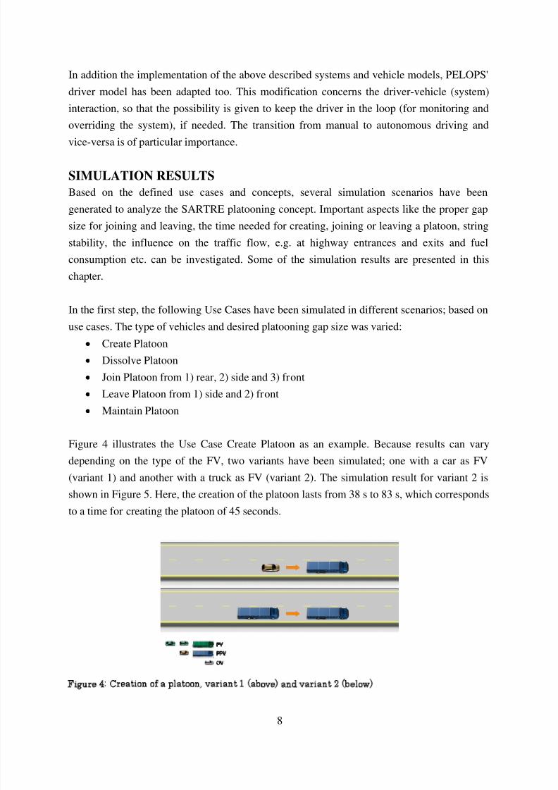
Figure 4 illustrates the Use Case Create Platoon as an example. Because results can vary
depending on the type of the FV, two variants have been simulated; one with a car as FV
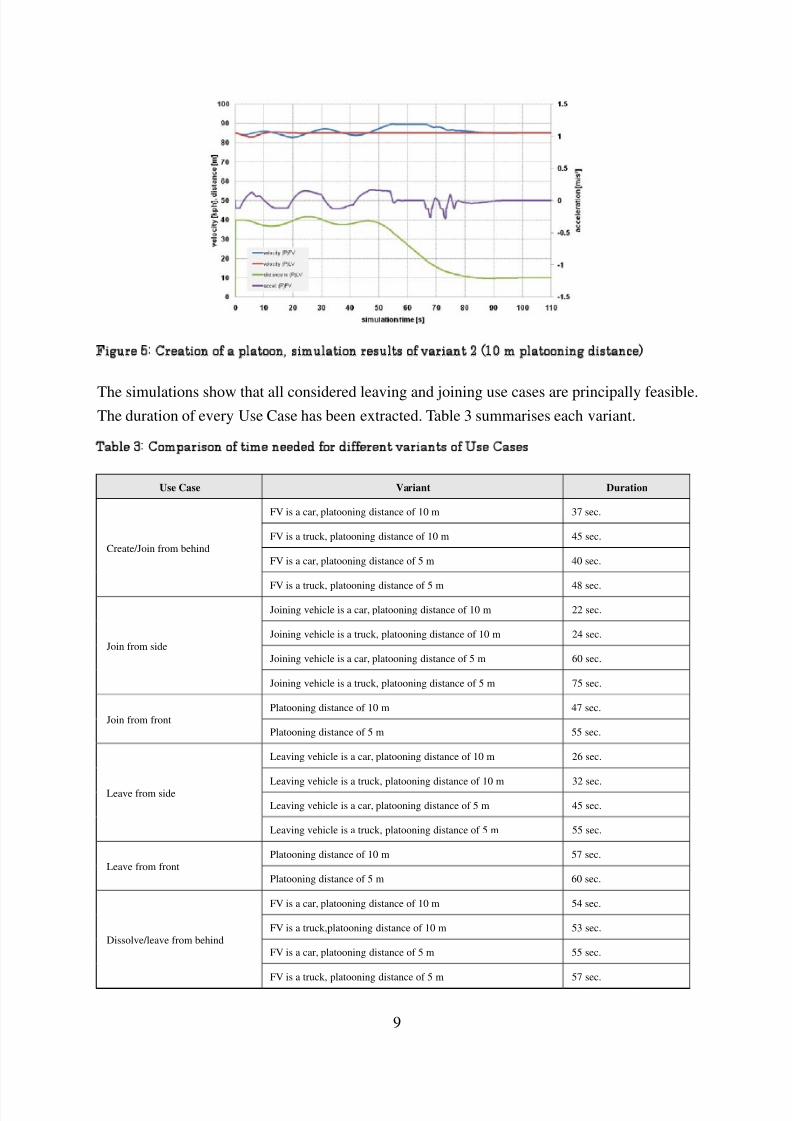
(variant 1) and another with a truck as FV (variant 2). The simulation result for variant 2 is
shown in Figure 5. Here, the creation of the platoon lasts from 38 s to 83 s, which corresponds
to a time for creating the platoon of 45 seconds.
Figure 4: Creation of a platoon, variant 1 (above) and variant 2 (below)
8/3/2019 ITS WC Challenges of Platooning Concept and Modelling
http://slidepdf.com/reader/full/its-wc-challenges-of-platooning-concept-and-modelling 9/12
9
Figure 5: Creation of a platoon, simulation results of variant 2 (10 m platooning distance)
The simulations show that all considered leaving and joining use cases are principally feasible.The duration of every Use Case has been extracted. Table 3 summarises each variant.
Table 3: Comparison of time needed for different variants of Use Cases
Use Case Variant Duration
Create/Join from behind
FV is a car, platooning distance of 10 m 37 sec.
FV is a truck, platooning distance of 10 m 45 sec.
FV is a car, platooning distance of 5 m 40 sec.
FV is a truck, platooning distance of 5 m 48 sec.
Join from side
Joining vehicle is a car, platooning distance of 10 m 22 sec.
Joining vehicle is a truck, platooning distance of 10 m 24 sec.
Joining vehicle is a car, platooning distance of 5 m 60 sec.
Joining vehicle is a truck, platooning distance of 5 m 75 sec.
Join from frontPlatooning distance of 10 m 47 sec.
Platooning distance of 5 m 55 sec.
Leave from side
Leaving vehicle is a car, platooning distance of 10 m 26 sec.
Leaving vehicle is a truck, platooning distance of 10 m 32 sec.
Leaving vehicle is a car, platooning distance of 5 m 45 sec.
Leaving vehicle is a truck, platooning distance of 5 m 55 sec.
Leave from frontPlatooning distance of 10 m 57 sec.
Platooning distance of 5 m 60 sec.
Dissolve/leave from behind
FV is a car, platooning distance of 10 m 54 sec.
FV is a truck,platooning distance of 10 m 53 sec.
FV is a car, platooning distance of 5 m 55 sec.
FV is a truck, platooning distance of 5 m 57 sec.
8/3/2019 ITS WC Challenges of Platooning Concept and Modelling
http://slidepdf.com/reader/full/its-wc-challenges-of-platooning-concept-and-modelling 10/12
10
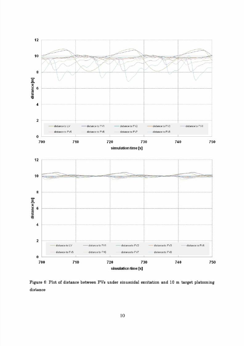
Figure 6: Plot of distance between PVs under sinusoidal excitation and 10 m target platooning
distance
8/3/2019 ITS WC Challenges of Platooning Concept and Modelling
http://slidepdf.com/reader/full/its-wc-challenges-of-platooning-concept-and-modelling 11/12
11
The durations (Table 3) vary from 22 to 75 seconds. Because of the limited acceleration
capabilities of trucks compared to cars, the Use Case variants with trucks have generally a
longer duration. The simulation showed that it is possible to reach string stability for the
systems used for a platoon with up to 10 vehicles on a flat road without curves. Figure 6 show
the plots for the distance of all PV for a 'sinusoidal excitation'. The LV is forced to follow asinusoidal velocity curve with a mean value of 80 kph, a period of 20 s and an amplitude of 3
kph. The first figure shows an unstable simulation and the second figure a stable control
behaviour after adjusting the controller parameter. In order to analyze the influence of the
inaccuracies in the sensor systems on the string stability, several simulations have been
conducted with sensor noises and inaccuracy. Two variants of sensor accuracy level have been
simulated. The first one is a +/-1% range and velocity inaccuracy level, which the current
available sensors can offer. And the second variants is a +/-10% inaccuracy level. The
simulation results showed that the sensor inaccuracy has impact on the string stability. Butcurrent available sensors have very low inaccuracy levels and thus the string stability can be
achieved with real sensors.
The final set of prioritised platooning strategies is still being defined on the project. Moving
from the generic platoon control strategy used in the above analysis to a tailored algorithm
that will be implemented in the implementation phase of SARTRE will lead to a more refined
understanding of the parameters. For this reason, the simulation work is being continued to
support the ongoing development and implementation of the demonstration system.
The agreement of a final set of parameters will be an iterative process (presentation and
discussion of simulation results definition of new simulations) that is likely to be
continued throughout the project.
PLATOON COMMUNICATION SYSTEM
The communication system can be seen as a complex data exchange mechanism within the
platoon, to potential platoon vehicles and to the back office. Communication between vehicles
is denoted V2V communication. The main task for V2V is communication to control and
coordinate the movement of the platoon – PUC. Communication between vehicle and BO is
denoted V2I communication. Hence the “infrastructure” refers to the BO. The main tasks for
V2I is business and guidance oriented communication, see BUC in the section on platoon
definitions.
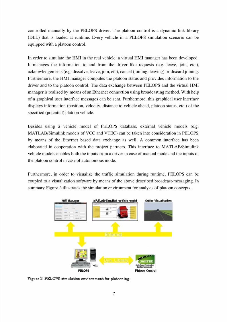
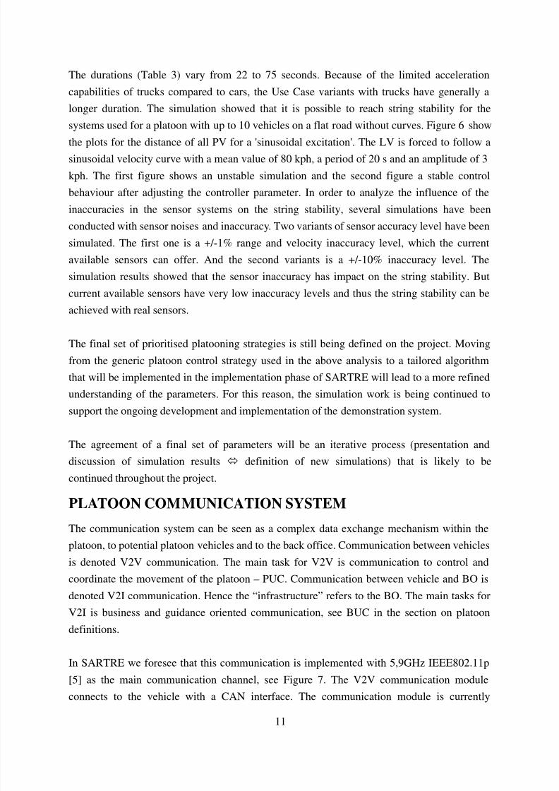
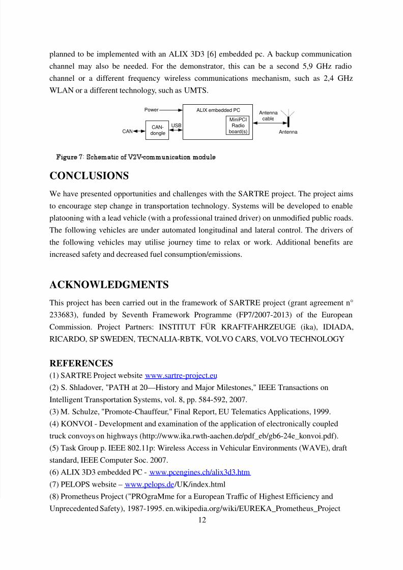
In SARTRE we foresee that this communication is implemented with 5,9GHz IEEE802.11p
[5] as the main communication channel, see Figure 7. The V2V communication module
connects to the vehicle with a CAN interface. The communication module is currently
8/3/2019 ITS WC Challenges of Platooning Concept and Modelling
http://slidepdf.com/reader/full/its-wc-challenges-of-platooning-concept-and-modelling 12/12
12
planned to be implemented with an ALIX 3D3 [6] embedded pc. A backup communication
channel may also be needed. For the demonstrator, this can be a second 5,9 GHz radio
channel or a different frequency wireless communications mechanism, such as 2,4 GHz
WLAN or a different technology, such as UMTS.
CONCLUSIONS
We have presented opportunities and challenges with the SARTRE project. The project aims
to encourage step change in transportation technology. Systems will be developed to enable
platooning with a lead vehicle (with a professional trained driver) on unmodified public roads.
The following vehicles are under automated longitudinal and lateral control. The drivers of
the following vehicles may utilise journey time to relax or work. Additional benefits are
increased safety and decreased fuel consumption/emissions.
ACKNOWLEDGMENTS
This project has been carried out in the framework of SARTRE project (grant agreement n°
233683), funded by Seventh Framework Programme (FP7/2007-2013) of the European
Commission. Project Partners: INSTITUT FÜR KRAFTFAHRZEUGE (ika), IDIADA,
RICARDO, SP SWEDEN, TECNALIA-RBTK, VOLVO CARS, VOLVO TECHNOLOGY
REFERENCES
(1) SARTRE Project website www.sartre-project.eu
(2) S. Shladover, "PATH at 20—History and Major Milestones," IEEE Transactions on
Intelligent Transportation Systems, vol. 8, pp. 584-592, 2007.(3) M. Schulze, "Promote-Chauffeur," Final Report, EU Telematics Applications, 1999.
(4) KONVOI - Development and examination of the application of electronically coupled
truck convoys on highways (http://www.ika.rwth-aachen.de/pdf_eb/gb6-24e_konvoi.pdf).
(5) Task Group p. IEEE 802.11p: Wireless Access in Vehicular Environments (WAVE), draft
standard, IEEE Computer Soc. 2007.
(6) ALIX 3D3 embedded PC - www.pcengines.ch/alix3d3.htm
(7) PELOPS website – www.pelops.de /UK/index.html
(8) Prometheus Project ("PROgraMme for a European Traffic of Highest Efficiency andUnprecedented Safety), 1987-1995. en.wikipedia.org/wiki/EUREKA_Prometheus_Project
ALIX embedded PCPower
CANCAN-dongle
USB
Antennacable
Antenna
MiniPCIRadio
board(s)
Figure 7: Schematic of V2V-communication module