iR 6000i Code List
21
COPYRIGHT © 2001 CANON INC. 2000 2000 2000 2000 CANON iR5000i/iR6000i REV.0 JUNE 2001 CHAPTER 6 SELF DIAGNOSIS 6-1 T 1. Er ror C odes 1.1 Li st of Er ro r Codes The machine is equipped with a mechanism to run self diagnosis to find out its condition (particularly of its sensors): CPU on the main controller PCB and the CPU on the DC con- troller PCB. If it finds a fault, it indicates the nature of the fault in its control panel. The following is a list of codes and descriptions (includin g timing of detection); a code may have detailed codes, which may be checked in service mode (COPIER> DISPLAY>JAM/ERR). E000 Main Cause The main t hermisto r (TH1 ) has poor cont act o r an o pen c ircui t. T he th erma l switch (TP1) has an open circuit. The fixing heater has an open circuit. The AC driver is faulty. The DC controller PCB is faulty. Mode of Detection 0000 After th e main po wer swi tch is t urned on, th e temp eratu re dete cted by the main thermistor does not reach 70°C. Ca ut ion The er ro r must be rese t in serv ic e mo de (COPIER>FUNCTION> CLEAR>ERR). E001 Main C ause The main ther mist or (TH1) h as a shor t cir cuit . Th e su b th ermi stor (TH2) has detected overheating. The AC driver is faulty. The DC controller PCB is faulty. Mode of Detection 0001 The ma in the rmist or or t he sub thermisto r has d etecte d abou t 230°C or higher for 2 sec. 0002 The ma in th ermis tor ha s dete cted 2 30°C or hig her (h ard cir cuit d e- tection). 0003 The s ub th ermis tor h as det ected about 236°C or h ighe r . Ca ut ion The er ro r must be rese t in serv ic e mo de (COPIER>FUNCTION> CLEAR>ERR).
-
Upload
aashish-chaudhari -
Category
Documents
-
view
239 -
download
1
Transcript of iR 6000i Code List
8/6/2019 iR 6000i Code List
http://slidepdf.com/reader/full/ir-6000i-code-list 1/21
COPYRIGHT © 2001 CANON INC. 2000 2000 2000 2000 CANON iR5000i/iR6000i REV.0 JUNE 2001
CHAPTER 6 SELF DIAGNOSIS
6-1 T
1. Error Codes
1.1 List of Error Codes
The machine is equipped with a mechanism to run self diagnosis to find out its condition(particularly of its sensors): CPU on the main controller PCB and the CPU on the DC con-
troller PCB. If it finds a fault, it indicates the nature of the fault in its control panel.
The following is a list of codes and descriptions (including timing of detection); a code
may have detailed codes, which may be checked in service mode (COPIER>
DISPLAY>JAM/ERR).
E000Main Cause The main thermistor (TH1) has poor contact or an open circuit. The thermal
switch (TP1) has an open circuit. The fixing heater has an open circuit. The
AC driver is faulty. The DC controller PCB is faulty.
Mode of
Detection
0000 After the main power switch is turned on, the temperature detected
by the main thermistor does not reach 70°C.
Caution The error must be reset in service mode (COPIER>FUNCTION>
CLEAR>ERR).
E001Main Cause The main thermistor (TH1) has a short circuit. The sub thermistor (TH2)
has detected overheating. The AC driver is faulty. The DC controller PCB is
faulty.
Mode of
Detection
0001 The main thermistor or the sub thermistor has detected about
230°C or higher for 2 sec.
0002 The main thermistor has detected 230°C or higher (hard circuit de-
tection).
0003 The sub thermistor has detected about 236°C or higher.
Caution The error must be reset in service mode (COPIER>FUNCTION>
CLEAR>ERR).
8/6/2019 iR 6000i Code List
http://slidepdf.com/reader/full/ir-6000i-code-list 2/21
COPYRIGHT © 2001 CANON INC. 2000 2000 2000 2000 CANON iR5000i/iR6000i REV.0 JUNE 2001
CHAPTER 6 SELF DIAGNOSIS
6-2 T
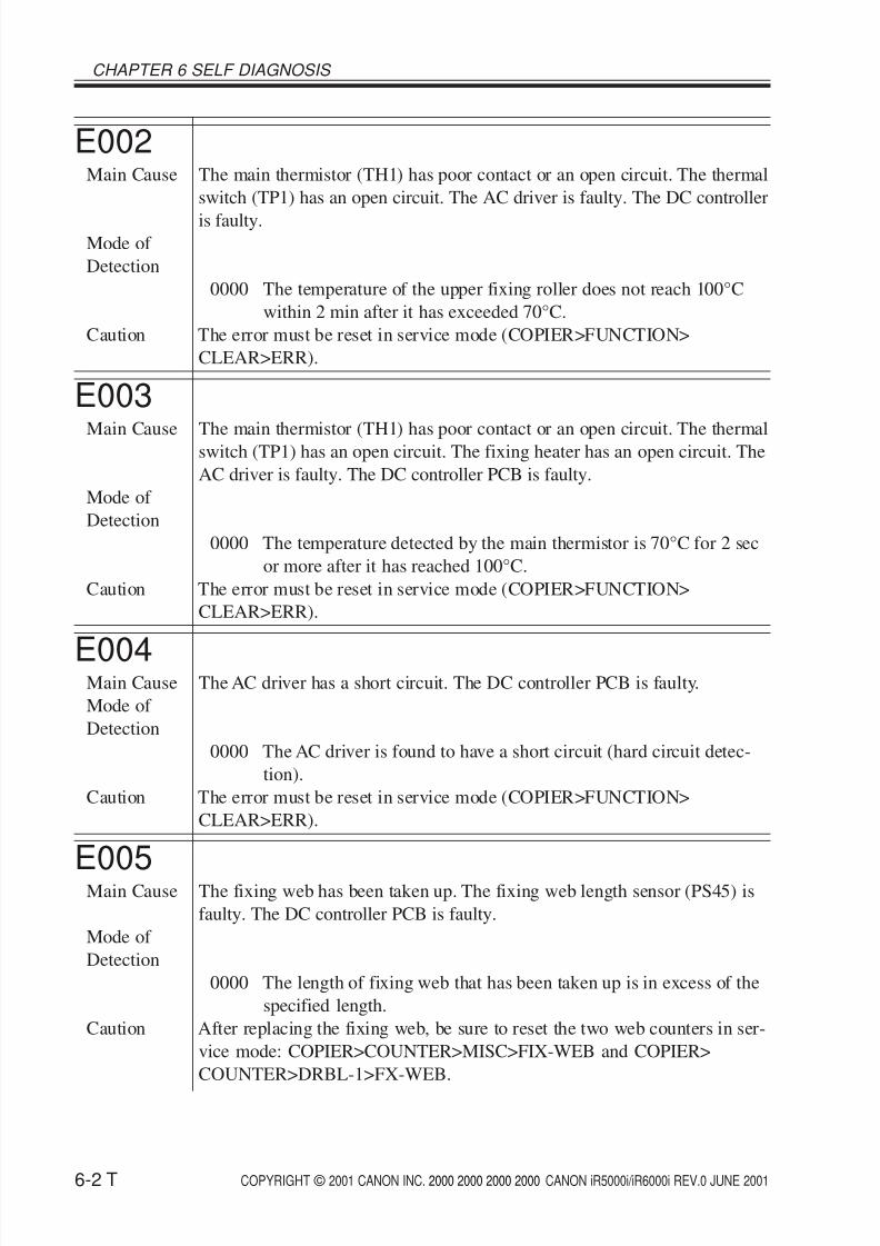
E002Main Cause The main thermistor (TH1) has poor contact or an open circuit. The thermal
switch (TP1) has an open circuit. The AC driver is faulty. The DC controller
is faulty.Mode of
Detection
0000 The temperature of the upper fixing roller does not reach 100°C
within 2 min after it has exceeded 70°C.
Caution The error must be reset in service mode (COPIER>FUNCTION>
CLEAR>ERR).
E003
Main Cause The main thermistor (TH1) has poor contact or an open circuit. The thermalswitch (TP1) has an open circuit. The fixing heater has an open circuit. The
AC driver is faulty. The DC controller PCB is faulty.
Mode of
Detection
0000 The temperature detected by the main thermistor is 70°C for 2 sec
or more after it has reached 100°C.
Caution The error must be reset in service mode (COPIER>FUNCTION>
CLEAR>ERR).
E004Main Cause The AC driver has a short circuit. The DC controller PCB is faulty.
Mode of
Detection
0000 The AC driver is found to have a short circuit (hard circuit detec-
tion).
Caution The error must be reset in service mode (COPIER>FUNCTION>
CLEAR>ERR).
E005Main Cause The fixing web has been taken up. The fixing web length sensor (PS45) is
faulty. The DC controller PCB is faulty.
Mode of
Detection
0000 The length of fixing web that has been taken up is in excess of the
specified length.
Caution After replacing the fixing web, be sure to reset the two web counters in ser-
vice mode: COPIER>COUNTER>MISC>FIX-WEB and COPIER>
COUNTER>DRBL-1>FX-WEB.
8/6/2019 iR 6000i Code List
http://slidepdf.com/reader/full/ir-6000i-code-list 3/21
COPYRIGHT © 2001 CANON INC. 2000 2000 2000 2000 CANON iR5000i/iR6000i REV.0 JUNE 2001
CHAPTER 6 SELF DIAGNOSIS
6-3 T
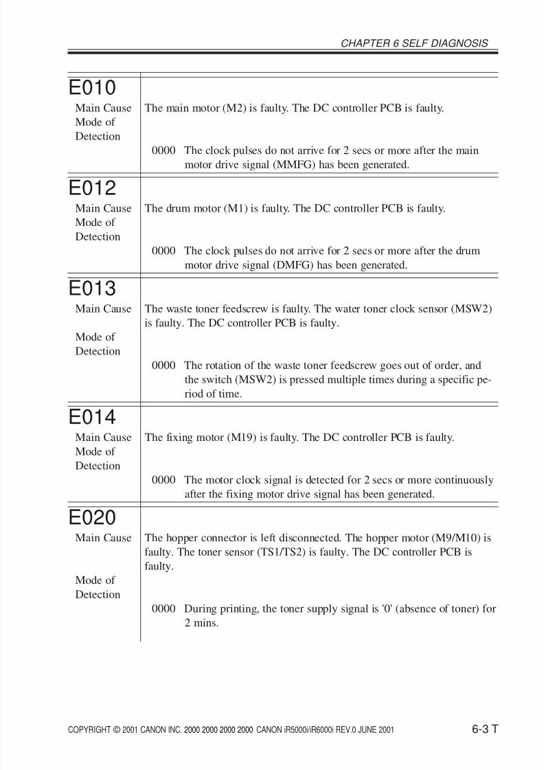
E010Main Cause The main motor (M2) is faulty. The DC controller PCB is faulty.
Mode of
Detection0000 The clock pulses do not arrive for 2 secs or more after the main
motor drive signal (MMFG) has been generated.
E012Main Cause The drum motor (M1) is faulty. The DC controller PCB is faulty.
Mode of
Detection
0000 The clock pulses do not arrive for 2 secs or more after the drum
motor drive signal (DMFG) has been generated.
E013Main Cause The waste toner feedscrew is faulty. The water toner clock sensor (MSW2)
is faulty. The DC controller PCB is faulty.
Mode of
Detection
0000 The rotation of the waste toner feedscrew goes out of order, and
the switch (MSW2) is pressed multiple times during a specific pe-
riod of time.
E014Main Cause The fixing motor (M19) is faulty. The DC controller PCB is faulty.
Mode of
Detection
0000 The motor clock signal is detected for 2 secs or more continuously
after the fixing motor drive signal has been generated.
E020Main Cause The hopper connector is left disconnected. The hopper motor (M9/M10) is
faulty. The toner sensor (TS1/TS2) is faulty. The DC controller PCB is
faulty.
Mode of
Detection
0000 During printing, the toner supply signal is '0' (absence of toner) for
2 mins.
8/6/2019 iR 6000i Code List
http://slidepdf.com/reader/full/ir-6000i-code-list 4/21
COPYRIGHT © 2001 CANON INC. 2000 2000 2000 2000 CANON iR5000i/iR6000i REV.0 JUNE 2001
CHAPTER 6 SELF DIAGNOSIS
6-4 T
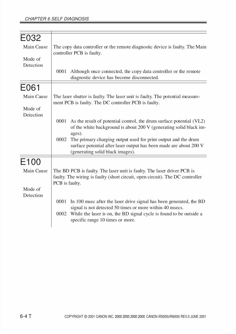
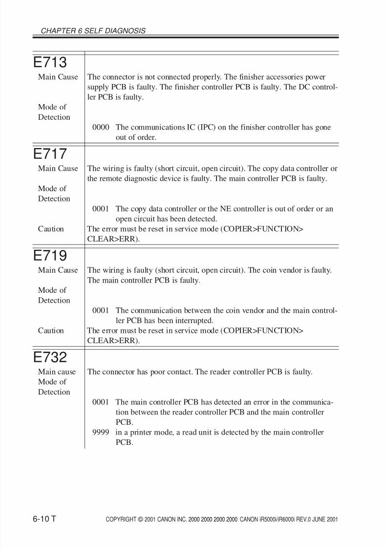
E032Main Cause The copy data controller or the remote diagnostic device is faulty. The Main
controller PCB is faulty.
Mode of Detection
0001 Although once connected, the copy data controller or the remote
diagnostic device has become disconnected.
E061Main Cause The laser shutter is faulty. The laser unit is faulty. The potential measure-
ment PCB is faulty. The DC controller PCB is faulty.
Mode of
Detection 0001 As the result of potential control, the drum surface potential (VL2)
of the white background is about 200 V (generating solid black im-
ages).
0002 The primary charging output used for print output and the drum
surface potential after laser output has been made are about 200 V
(generating solid black images).
E100Main Cause The BD PCB is faulty. The laser unit is faulty. The laser driver PCB is
faulty. The wiring is faulty (short circuit, open circuit). The DC controllerPCB is faulty.
Mode of
Detection
0001 In 100 msec after the laser drive signal has been generated, the BD
signal is not detected 50 times or more within 40 msecs.
0002 While the laser is on, the BD signal cycle is found to be outside a
specific range 10 times or more.
8/6/2019 iR 6000i Code List
http://slidepdf.com/reader/full/ir-6000i-code-list 5/21
COPYRIGHT © 2001 CANON INC. 2000 2000 2000 2000 CANON iR5000i/iR6000i REV.0 JUNE 2001
CHAPTER 6 SELF DIAGNOSIS
6-5 T
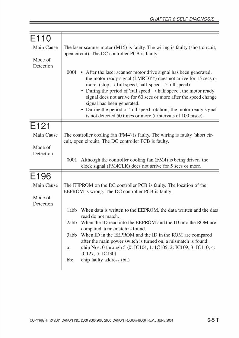
E110Main Cause The laser scanner motor (M15) is faulty. The wiring is faulty (short circuit,
open circuit). The DC controller PCB is faulty.
Mode of Detection
0001 • After the laser scanner motor drive signal has been generated,
the motor ready signal (LMRDY*) does not arrive for 15 secs or
more. (stop→ full speed, half-speed→ full speed)
• During the period of 'full speed→ half speed', the motor ready
signal does not arrive for 60 secs or more after the speed change
signal has been generated.
• During the period of 'full speed rotation', the motor ready signal
is not detected 50 times or more (t intervals of 100 msec).
E121Main Cause The controller cooling fan (FM4) is faulty. The wiring is faulty (short cir-
cuit, open circuit). The DC controller PCB is faulty.
Mode of
Detection
0001 Although the controller cooling fan (FM4) is being driven, the
clock signal (FM4CLK) does not arrive for 5 secs or more.
E196Main Cause The EEPROM on the DC controller PCB is faulty. The location of the
EEPROM is wrong. The DC controller PCB is faulty.
Mode of
Detection
1abb When data is written to the EEPROM, the data written and the data
read do not match.
2abb When the ID read into the EEPROM and the ID into the ROM are
compared, a mismatch is found.
3abb When ID in the EEPROM and the ID in the ROM are comparedafter the main power switch is turned on, a mismatch is found.
a: chip Nos. 0 through 5 (0: IC104, 1: IC105, 2: IC109, 3: IC110, 4:
IC127, 5: IC130)
bb: chip faulty address (bit)

8/6/2019 iR 6000i Code List
http://slidepdf.com/reader/full/ir-6000i-code-list 6/21
COPYRIGHT © 2001 CANON INC. 2000 2000 2000 2000 CANON iR5000i/iR6000i REV.0 JUNE 2001
CHAPTER 6 SELF DIAGNOSIS
6-6 T
E202Main Cause The scanner HP sensor (PS39) is faulty. The scanner motor (M3) is faulty.
The reader controller PCB is faulty.
Mode of Detection
0001 The scanner HP sensor does not turn off even when the scanner has
been moved 40 mm forward after the main power switch has been
turned on or the Start key has been pressed.
0002 The scanner HP sensor does not turn on even when the scanner has
been moved 450 mm in reverse.
E204
Main Cause The ADF controller PCB is faulty. The reader controller PCB is faulty.Mode of
Detection
0001 During printing, the image leading edge signal does not arrive from
the ADF.
E220Main Cause The lamp inverter PCB is faulty. The reader controller PCB is faulty.
Mode of
Detection
0001 The lamp inverter PCB is found to have a fault.
E225Main Cause The scanning lamp (xenon tube) is faulty. The inverter PCB is faulty. The
CCD/AP PCB is faulty. The reader controller PCB is faulty.
Mode of
Detection
0000 A specific signal level cannot be attained by CCD gain correction
at power-on.
0002 The edge gain correction value changed more than a specific levelcompared with the correction value used for the preceding sheet.
E240Main Cause The main controller PCB. The DC controller PCB is faulty.
Mode of
Detection
0000 An error has occurred in the communication between the main
controller PCB and the CPU of the DC controller PCB.
010B An error occurred in the sequence during printing.
8/6/2019 iR 6000i Code List
http://slidepdf.com/reader/full/ir-6000i-code-list 7/21
COPYRIGHT © 2001 CANON INC. 2000 2000 2000 2000 CANON iR5000i/iR6000i REV.0 JUNE 2001
CHAPTER 6 SELF DIAGNOSIS
6-7 T
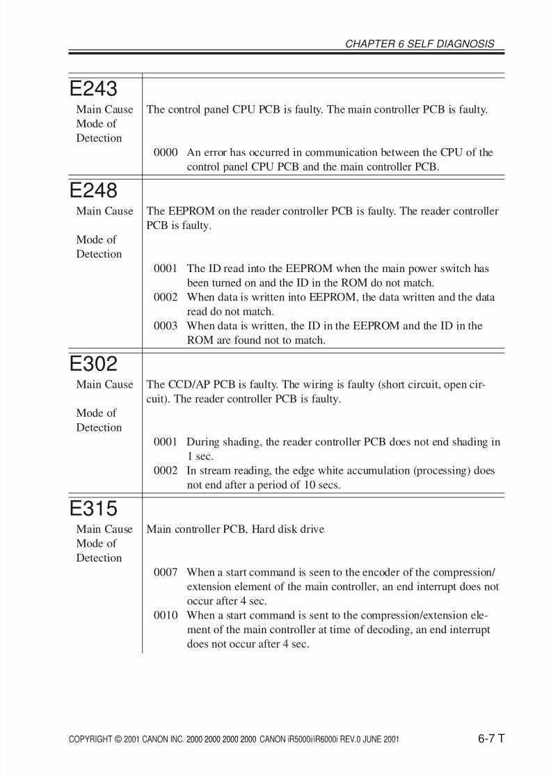
E243Main Cause The control panel CPU PCB is faulty. The main controller PCB is faulty.
Mode of
Detection0000 An error has occurred in communication between the CPU of the
control panel CPU PCB and the main controller PCB.
E248Main Cause The EEPROM on the reader controller PCB is faulty. The reader controller
PCB is faulty.
Mode of
Detection
0001 The ID read into the EEPROM when the main power switch hasbeen turned on and the ID in the ROM do not match.
0002 When data is written into EEPROM, the data written and the data
read do not match.
0003 When data is written, the ID in the EEPROM and the ID in the
ROM are found not to match.
E302Main Cause The CCD/AP PCB is faulty. The wiring is faulty (short circuit, open cir-
cuit). The reader controller PCB is faulty.
Mode of Detection
0001 During shading, the reader controller PCB does not end shading in
1 sec.
0002 In stream reading, the edge white accumulation (processing) does
not end after a period of 10 secs.
E315Main Cause Main controller PCB, Hard disk drive
Mode of Detection
0007 When a start command is seen to the encoder of the compression/
extension element of the main controller, an end interrupt does not
occur after 4 sec.
0010 When a start command is sent to the compression/extension ele-
ment of the main controller at time of decoding, an end interrupt
does not occur after 4 sec.
8/6/2019 iR 6000i Code List
http://slidepdf.com/reader/full/ir-6000i-code-list 8/21
COPYRIGHT © 2001 CANON INC. 2000 2000 2000 2000 CANON iR5000i/iR6000i REV.0 JUNE 2001
CHAPTER 6 SELF DIAGNOSIS
6-8 T
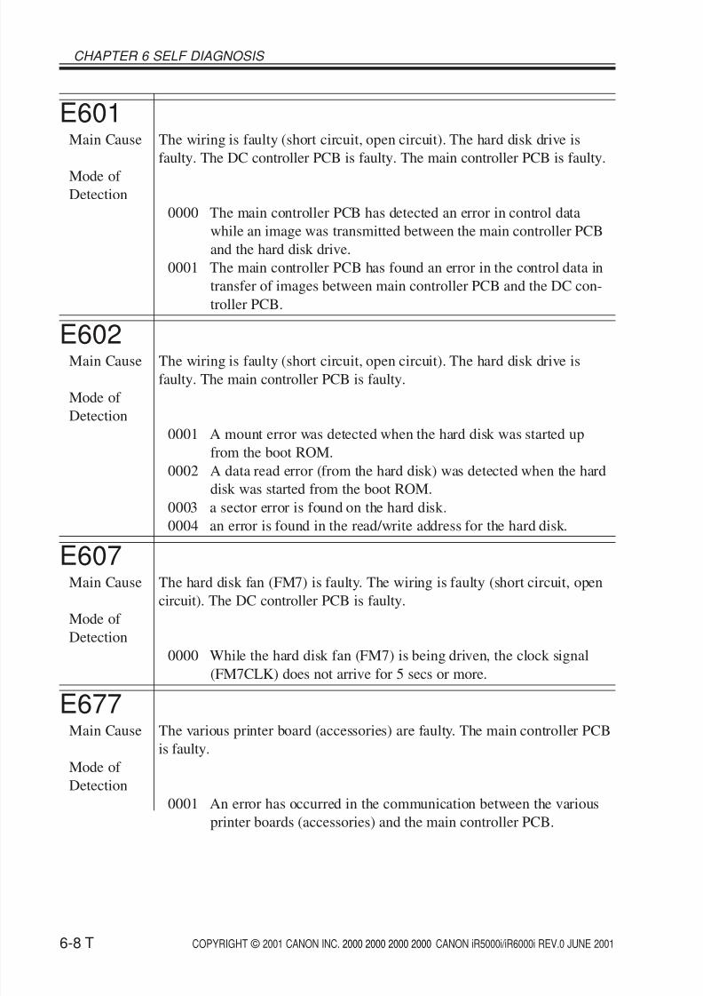
E601Main Cause The wiring is faulty (short circuit, open circuit). The hard disk drive is
faulty. The DC controller PCB is faulty. The main controller PCB is faulty.
Mode of Detection
0000 The main controller PCB has detected an error in control data
while an image was transmitted between the main controller PCB
and the hard disk drive.
0001 The main controller PCB has found an error in the control data in
transfer of images between main controller PCB and the DC con-
troller PCB.
E602Main Cause The wiring is faulty (short circuit, open circuit). The hard disk drive is
faulty. The main controller PCB is faulty.
Mode of
Detection
0001 A mount error was detected when the hard disk was started up
from the boot ROM.
0002 A data read error (from the hard disk) was detected when the hard
disk was started from the boot ROM.
0003 a sector error is found on the hard disk.
0004 an error is found in the read/write address for the hard disk.
E607Main Cause The hard disk fan (FM7) is faulty. The wiring is faulty (short circuit, open
circuit). The DC controller PCB is faulty.
Mode of
Detection
0000 While the hard disk fan (FM7) is being driven, the clock signal
(FM7CLK) does not arrive for 5 secs or more.
E677Main Cause The various printer board (accessories) are faulty. The main controller PCB
is faulty.
Mode of
Detection
0001 An error has occurred in the communication between the various
printer boards (accessories) and the main controller PCB.
8/6/2019 iR 6000i Code List
http://slidepdf.com/reader/full/ir-6000i-code-list 9/21
COPYRIGHT © 2001 CANON INC. 2000 2000 2000 2000 CANON iR5000i/iR6000i REV.0 JUNE 2001
CHAPTER 6 SELF DIAGNOSIS
6-9 T
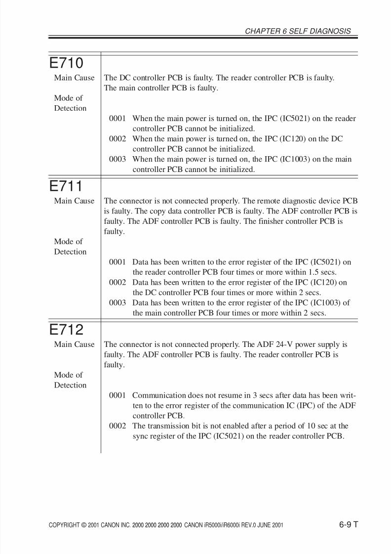
E710Main Cause The DC controller PCB is faulty. The reader controller PCB is faulty.
The main controller PCB is faulty.
Mode of Detection
0001 When the main power is turned on, the IPC (IC5021) on the reader
controller PCB cannot be initialized.
0002 When the main power is turned on, the IPC (IC120) on the DC
controller PCB cannot be initialized.
0003 When the main power is turned on, the IPC (IC1003) on the main
controller PCB cannot be initialized.
E711Main Cause The connector is not connected properly. The remote diagnostic device PCB
is faulty. The copy data controller PCB is faulty. The ADF controller PCB is
faulty. The ADF controller PCB is faulty. The finisher controller PCB is
faulty.
Mode of
Detection
0001 Data has been written to the error register of the IPC (IC5021) on
the reader controller PCB four times or more within 1.5 secs.
0002 Data has been written to the error register of the IPC (IC120) on
the DC controller PCB four times or more within 2 secs.0003 Data has been written to the error register of the IPC (IC1003) of
the main controller PCB four times or more within 2 secs.
E712Main Cause The connector is not connected properly. The ADF 24-V power supply is
faulty. The ADF controller PCB is faulty. The reader controller PCB is
faulty.
Mode of
Detection0001 Communication does not resume in 3 secs after data has been writ-
ten to the error register of the communication IC (IPC) of the ADF
controller PCB.
0002 The transmission bit is not enabled after a period of 10 sec at the
sync register of the IPC (IC5021) on the reader controller PCB.
8/6/2019 iR 6000i Code List
http://slidepdf.com/reader/full/ir-6000i-code-list 10/21
8/6/2019 iR 6000i Code List
http://slidepdf.com/reader/full/ir-6000i-code-list 11/21
COPYRIGHT © 2001 CANON INC. 2000 2000 2000 2000 CANON iR5000i/iR6000i REV.0 JUNE 2001
CHAPTER 6 SELF DIAGNOSIS
6-11 T
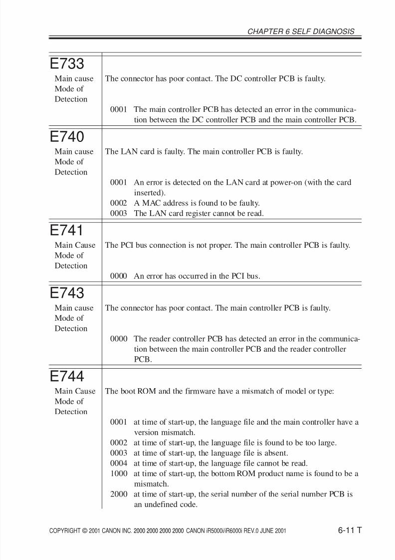
E733Main cause The connector has poor contact. The DC controller PCB is faulty.
Mode of
Detection0001 The main controller PCB has detected an error in the communica-
tion between the DC controller PCB and the main controller PCB.
E740Main cause The LAN card is faulty. The main controller PCB is faulty.
Mode of
Detection
0001 An error is detected on the LAN card at power-on (with the card
inserted).0002 A MAC address is found to be faulty.
0003 The LAN card register cannot be read.
E741Main Cause The PCI bus connection is not proper. The main controller PCB is faulty.
Mode of
Detection
0000 An error has occurred in the PCI bus.
E743Main cause The connector has poor contact. The main controller PCB is faulty.
Mode of
Detection
0000 The reader controller PCB has detected an error in the communica-
tion between the main controller PCB and the reader controller
PCB.
E744Main Cause The boot ROM and the firmware have a mismatch of model or type:Mode of
Detection
0001 at time of start-up, the language file and the main controller have a
version mismatch.
0002 at time of start-up, the language file is found to be too large.
0003 at time of start-up, the language file is absent.
0004 at time of start-up, the language file cannot be read.
1000 at time of start-up, the bottom ROM product name is found to be a
mismatch.
2000 at time of start-up, the serial number of the serial number PCB is
an undefined code.
8/6/2019 iR 6000i Code List
http://slidepdf.com/reader/full/ir-6000i-code-list 12/21
COPYRIGHT © 2001 CANON INC. 2000 2000 2000 2000 CANON iR5000i/iR6000i REV.0 JUNE 2001
CHAPTER 6 SELF DIAGNOSIS
6-12 T
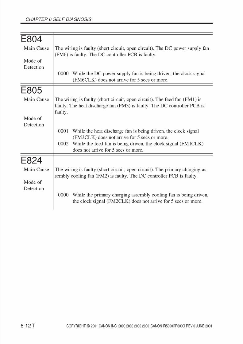
E804Main Cause The wiring is faulty (short circuit, open circuit). The DC power supply fan
(FM6) is faulty. The DC controller PCB is faulty.
Mode of Detection
0000 While the DC power supply fan is being driven, the clock signal
(FM6CLK) does not arrive for 5 secs or more.
E805Main Cause The wiring is faulty (short circuit, open circuit). The feed fan (FM1) is
faulty. The heat discharge fan (FM3) is faulty. The DC controller PCB is
faulty.
Mode of Detection
0001 While the heat discharge fan is being driven, the clock signal
(FM3CLK) does not arrive for 5 secs or more.
0002 While the feed fan is being driven, the clock signal (FM1CLK)
does not arrive for 5 secs or more.
E824Main Cause The wiring is faulty (short circuit, open circuit). The primary charging as-
sembly cooling fan (FM2) is faulty. The DC controller PCB is faulty.
Mode of Detection
0000 While the primary charging assembly cooling fan is being driven,
the clock signal (FM2CLK) does not arrive for 5 secs or more.
8/6/2019 iR 6000i Code List
http://slidepdf.com/reader/full/ir-6000i-code-list 13/21
COPYRIGHT © 2001 CANON INC. 2000 2000 2000 2000 CANON iR5000i/iR6000i REV.0 JUNE 2001
CHAPTER 6 SELF DIAGNOSIS
6-13 T
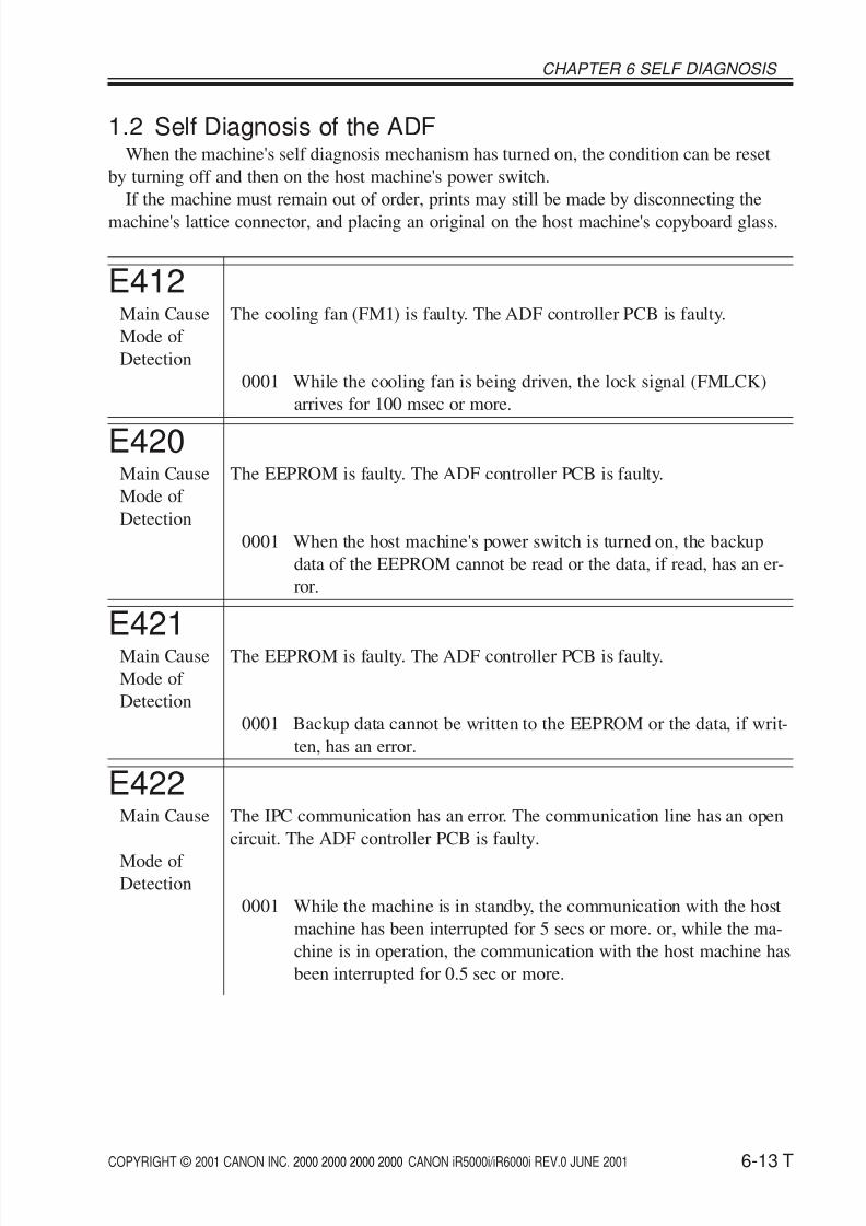
1.2 Self Diagnosis of the ADFWhen the machine's self diagnosis mechanism has turned on, the condition can be reset
by turning off and then on the host machine's power switch.
If the machine must remain out of order, prints may still be made by disconnecting the
machine's lattice connector, and placing an original on the host machine's copyboard glass.
E412Main Cause The cooling fan (FM1) is faulty. The ADF controller PCB is faulty.
Mode of
Detection
0001 While the cooling fan is being driven, the lock signal (FMLCK)
arrives for 100 msec or more.
E420Main Cause The EEPROM is faulty. The ADF controller PCB is faulty.
Mode of
Detection
0001 When the host machine's power switch is turned on, the backup
data of the EEPROM cannot be read or the data, if read, has an er-
ror.
E421Main Cause The EEPROM is faulty. The ADF controller PCB is faulty.
Mode of
Detection
0001 Backup data cannot be written to the EEPROM or the data, if writ-
ten, has an error.
E422Main Cause The IPC communication has an error. The communication line has an open
circuit. The ADF controller PCB is faulty.
Mode of Detection
0001 While the machine is in standby, the communication with the host
machine has been interrupted for 5 secs or more. or, while the ma-
chine is in operation, the communication with the host machine has
been interrupted for 0.5 sec or more.
8/6/2019 iR 6000i Code List
http://slidepdf.com/reader/full/ir-6000i-code-list 14/21
COPYRIGHT © 2001 CANON INC. 2000 2000 2000 2000 CANON iR5000i/iR6000i REV.0 JUNE 2001
CHAPTER 6 SELF DIAGNOSIS
6-14 T
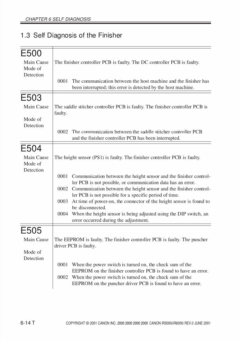
1.3 Self Diagnosis of the Finisher
E500Main Cause The finisher controller PCB is faulty. The DC controller PCB is faulty.
Mode of
Detection
0001 The communication between the host machine and the finisher has
been interrupted; this error is detected by the host machine.
E503Main Cause The saddle stitcher controller PCB is faulty. The finisher controller PCB is
faulty.
Mode of Detection
0002 The communication between the saddle stitcher controller PCB
and the finisher controller PCB has been interrupted.
E504Main Cause The height sensor (PS1) is faulty. The finisher controller PCB is faulty.
Mode of
Detection
0001 Communication between the height sensor and the finisher control-
ler PCB is not possible, or communication data has an error.
0002 Communication between the height sensor and the finisher control-
ler PCB is not possible for a specific period of time.
0003 At time of power-on, the connector of the height sensor is found to
be disconnected.
0004 When the height sensor is being adjusted using the DIP switch, an
error occurred during the adjustment.
E505Main Cause The EEPROM is faulty. The finisher controller PCB is faulty. The puncher
driver PCB is faulty.
Mode of
Detection
0001 When the power switch is turned on, the check sum of the
EEPROM on the finisher controller PCB is found to have an error.
0002 When the power switch is turned on, the check sum of the
EEPROM on the puncher driver PCB is found to have an error.
8/6/2019 iR 6000i Code List
http://slidepdf.com/reader/full/ir-6000i-code-list 15/21
COPYRIGHT © 2001 CANON INC. 2000 2000 2000 2000 CANON iR5000i/iR6000i REV.0 JUNE 2001
CHAPTER 6 SELF DIAGNOSIS
6-15 T
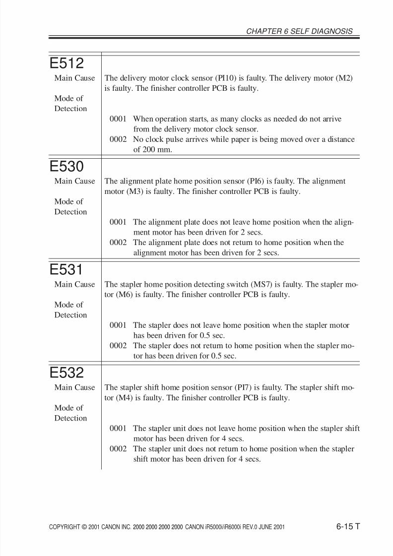
E512Main Cause The delivery motor clock sensor (PI10) is faulty. The delivery motor (M2)
is faulty. The finisher controller PCB is faulty.
Mode of Detection
0001 When operation starts, as many clocks as needed do not arrive
from the delivery motor clock sensor.
0002 No clock pulse arrives while paper is being moved over a distance
of 200 mm.
E530Main Cause The alignment plate home position sensor (PI6) is faulty. The alignment
motor (M3) is faulty. The finisher controller PCB is faulty.Mode of
Detection
0001 The alignment plate does not leave home position when the align-
ment motor has been driven for 2 secs.
0002 The alignment plate does not return to home position when the
alignment motor has been driven for 2 secs.
E531Main Cause The stapler home position detecting switch (MS7) is faulty. The stapler mo-
tor (M6) is faulty. The finisher controller PCB is faulty.Mode of
Detection
0001 The stapler does not leave home position when the stapler motor
has been driven for 0.5 sec.
0002 The stapler does not return to home position when the stapler mo-
tor has been driven for 0.5 sec.
E532Main Cause The stapler shift home position sensor (PI7) is faulty. The stapler shift mo-
tor (M4) is faulty. The finisher controller PCB is faulty.
Mode of
Detection
0001 The stapler unit does not leave home position when the stapler shift
motor has been driven for 4 secs.
0002 The stapler unit does not return to home position when the stapler
shift motor has been driven for 4 secs.
8/6/2019 iR 6000i Code List
http://slidepdf.com/reader/full/ir-6000i-code-list 16/21
COPYRIGHT © 2001 CANON INC. 2000 2000 2000 2000 CANON iR5000i/iR6000i REV.0 JUNE 2001
CHAPTER 6 SELF DIAGNOSIS
6-16 T
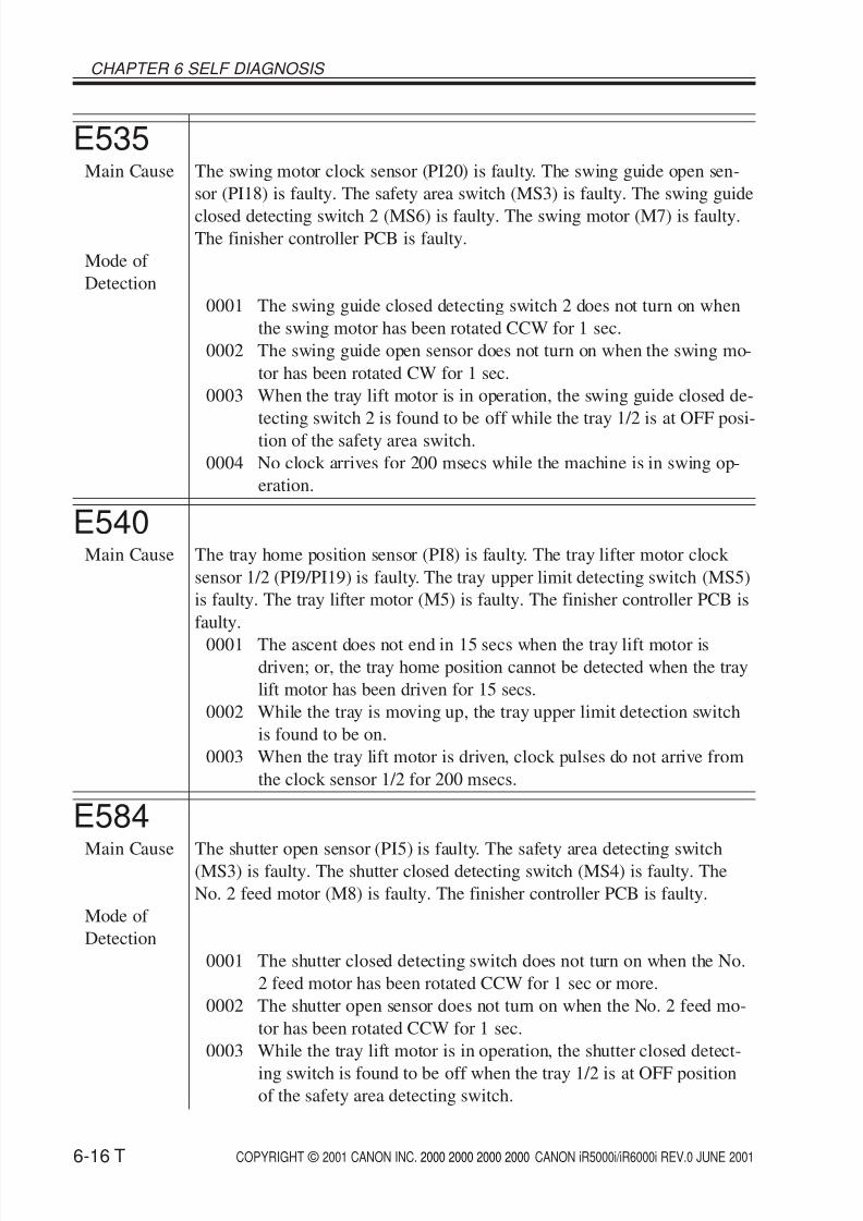
E535Main Cause The swing motor clock sensor (PI20) is faulty. The swing guide open sen-
sor (PI18) is faulty. The safety area switch (MS3) is faulty. The swing guide
closed detecting switch 2 (MS6) is faulty. The swing motor (M7) is faulty.The finisher controller PCB is faulty.
Mode of
Detection
0001 The swing guide closed detecting switch 2 does not turn on when
the swing motor has been rotated CCW for 1 sec.
0002 The swing guide open sensor does not turn on when the swing mo-
tor has been rotated CW for 1 sec.
0003 When the tray lift motor is in operation, the swing guide closed de-
tecting switch 2 is found to be off while the tray 1/2 is at OFF posi-
tion of the safety area switch.
0004 No clock arrives for 200 msecs while the machine is in swing op-
eration.
E540Main Cause The tray home position sensor (PI8) is faulty. The tray lifter motor clock
sensor 1/2 (PI9/PI19) is faulty. The tray upper limit detecting switch (MS5)
is faulty. The tray lifter motor (M5) is faulty. The finisher controller PCB is
faulty.
0001 The ascent does not end in 15 secs when the tray lift motor isdriven; or, the tray home position cannot be detected when the tray
lift motor has been driven for 15 secs.
0002 While the tray is moving up, the tray upper limit detection switch
is found to be on.
0003 When the tray lift motor is driven, clock pulses do not arrive from
the clock sensor 1/2 for 200 msecs.
E584
Main Cause The shutter open sensor (PI5) is faulty. The safety area detecting switch(MS3) is faulty. The shutter closed detecting switch (MS4) is faulty. The
No. 2 feed motor (M8) is faulty. The finisher controller PCB is faulty.
Mode of
Detection
0001 The shutter closed detecting switch does not turn on when the No.
2 feed motor has been rotated CCW for 1 sec or more.
0002 The shutter open sensor does not turn on when the No. 2 feed mo-
tor has been rotated CCW for 1 sec.
0003 While the tray lift motor is in operation, the shutter closed detect-
ing switch is found to be off when the tray 1/2 is at OFF positionof the safety area detecting switch.
8/6/2019 iR 6000i Code List
http://slidepdf.com/reader/full/ir-6000i-code-list 17/21
COPYRIGHT © 2001 CANON INC. 2000 2000 2000 2000 CANON iR5000i/iR6000i REV.0 JUNE 2001
CHAPTER 6 SELF DIAGNOSIS
6-17 T
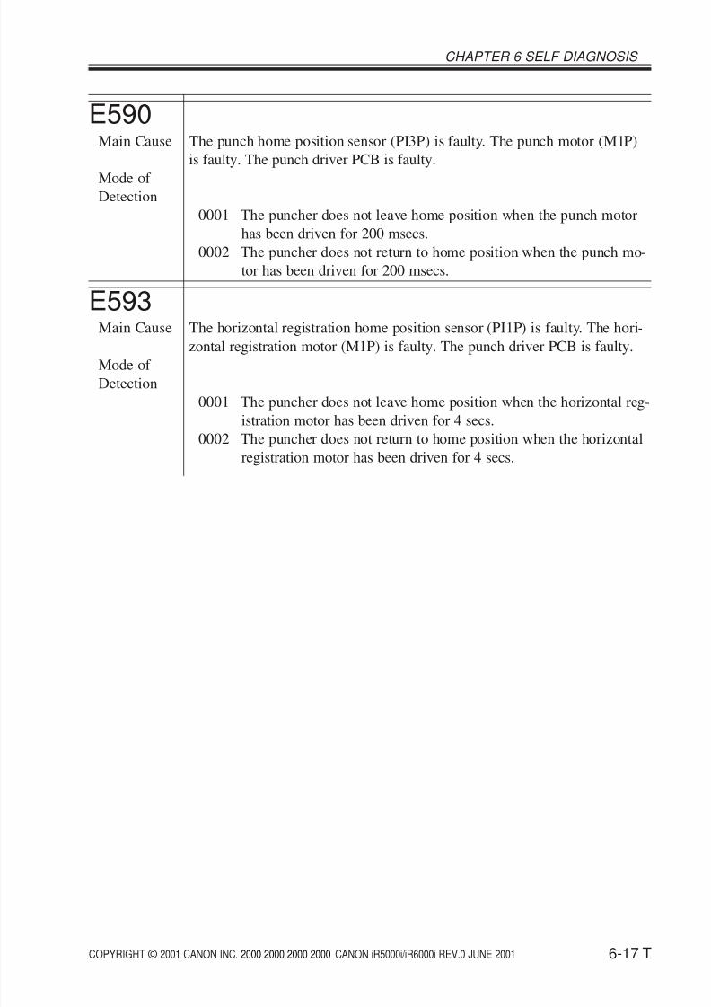
E590Main Cause The punch home position sensor (PI3P) is faulty. The punch motor (M1P)
is faulty. The punch driver PCB is faulty.
Mode of Detection
0001 The puncher does not leave home position when the punch motor
has been driven for 200 msecs.
0002 The puncher does not return to home position when the punch mo-
tor has been driven for 200 msecs.
E593Main Cause The horizontal registration home position sensor (PI1P) is faulty. The hori-
zontal registration motor (M1P) is faulty. The punch driver PCB is faulty.Mode of
Detection
0001 The puncher does not leave home position when the horizontal reg-
istration motor has been driven for 4 secs.
0002 The puncher does not return to home position when the horizontal
registration motor has been driven for 4 secs.
8/6/2019 iR 6000i Code List
http://slidepdf.com/reader/full/ir-6000i-code-list 18/21
COPYRIGHT © 2001 CANON INC. 2000 2000 2000 2000 CANON iR5000i/iR6000i REV.0 JUNE 2001
CHAPTER 6 SELF DIAGNOSIS
6-18 T
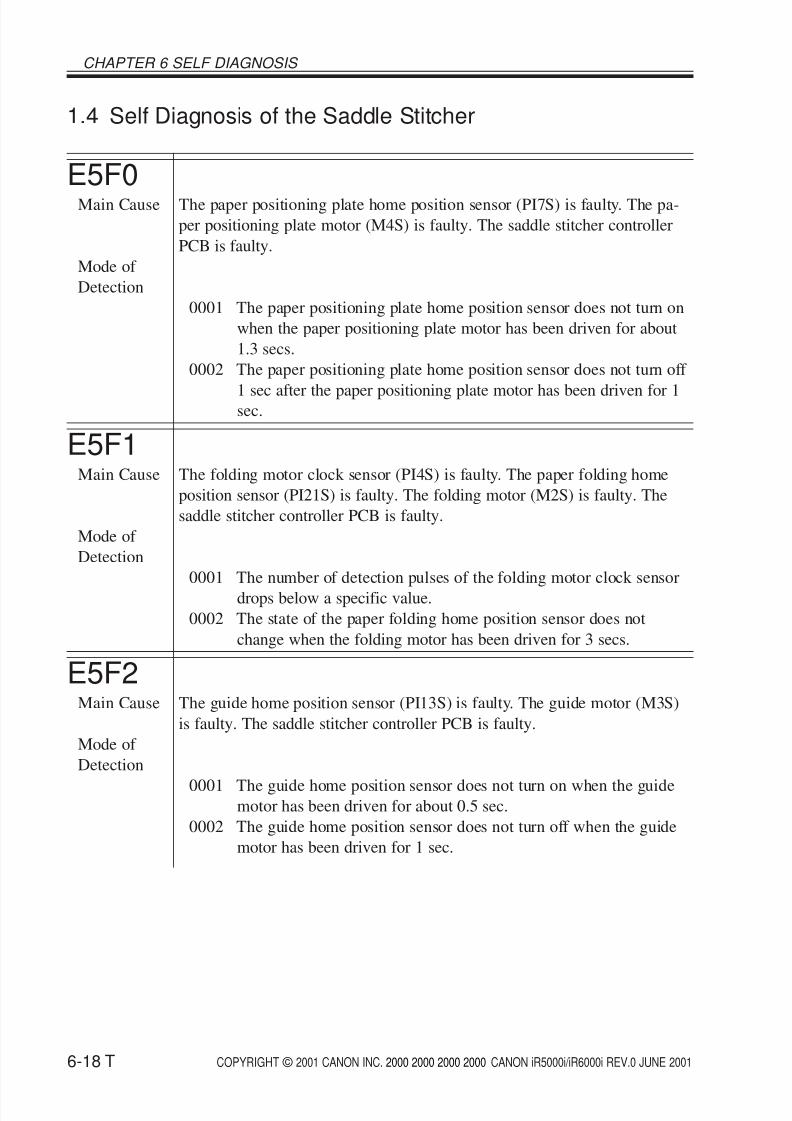
1.4 Self Diagnosis of the Saddle Stitcher
E5F0Main Cause The paper positioning plate home position sensor (PI7S) is faulty. The pa-
per positioning plate motor (M4S) is faulty. The saddle stitcher controller
PCB is faulty.
Mode of
Detection
0001 The paper positioning plate home position sensor does not turn on
when the paper positioning plate motor has been driven for about
1.3 secs.
0002 The paper positioning plate home position sensor does not turn off
1 sec after the paper positioning plate motor has been driven for 1sec.
E5F1Main Cause The folding motor clock sensor (PI4S) is faulty. The paper folding home
position sensor (PI21S) is faulty. The folding motor (M2S) is faulty. The
saddle stitcher controller PCB is faulty.
Mode of
Detection
0001 The number of detection pulses of the folding motor clock sensor
drops below a specific value.
0002 The state of the paper folding home position sensor does not
change when the folding motor has been driven for 3 secs.
E5F2Main Cause The guide home position sensor (PI13S) is faulty. The guide motor (M3S)
is faulty. The saddle stitcher controller PCB is faulty.
Mode of
Detection
0001 The guide home position sensor does not turn on when the guidemotor has been driven for about 0.5 sec.
0002 The guide home position sensor does not turn off when the guide
motor has been driven for 1 sec.
8/6/2019 iR 6000i Code List
http://slidepdf.com/reader/full/ir-6000i-code-list 19/21
COPYRIGHT © 2001 CANON INC. 2000 2000 2000 2000 CANON iR5000i/iR6000i REV.0 JUNE 2001
CHAPTER 6 SELF DIAGNOSIS
6-19 T
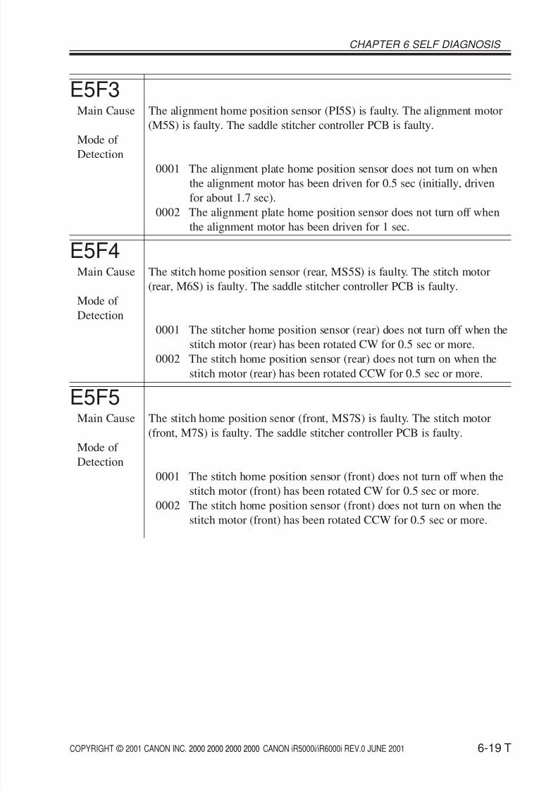
E5F3Main Cause The alignment home position sensor (PI5S) is faulty. The alignment motor
(M5S) is faulty. The saddle stitcher controller PCB is faulty.
Mode of Detection
0001 The alignment plate home position sensor does not turn on when
the alignment motor has been driven for 0.5 sec (initially, driven
for about 1.7 sec).
0002 The alignment plate home position sensor does not turn off when
the alignment motor has been driven for 1 sec.
E5F4
Main Cause The stitch home position sensor (rear, MS5S) is faulty. The stitch motor(rear, M6S) is faulty. The saddle stitcher controller PCB is faulty.
Mode of
Detection
0001 The stitcher home position sensor (rear) does not turn off when the
stitch motor (rear) has been rotated CW for 0.5 sec or more.
0002 The stitch home position sensor (rear) does not turn on when the
stitch motor (rear) has been rotated CCW for 0.5 sec or more.
E5F5Main Cause The stitch home position senor (front, MS7S) is faulty. The stitch motor
(front, M7S) is faulty. The saddle stitcher controller PCB is faulty.
Mode of
Detection
0001 The stitch home position sensor (front) does not turn off when the
stitch motor (front) has been rotated CW for 0.5 sec or more.
0002 The stitch home position sensor (front) does not turn on when the
stitch motor (front) has been rotated CCW for 0.5 sec or more.
8/6/2019 iR 6000i Code List
http://slidepdf.com/reader/full/ir-6000i-code-list 20/21
COPYRIGHT © 2001 CANON INC. 2000 2000 2000 2000 CANON iR5000i/iR6000i REV.0 JUNE 2001
CHAPTER 6 SELF DIAGNOSIS
6-20 T
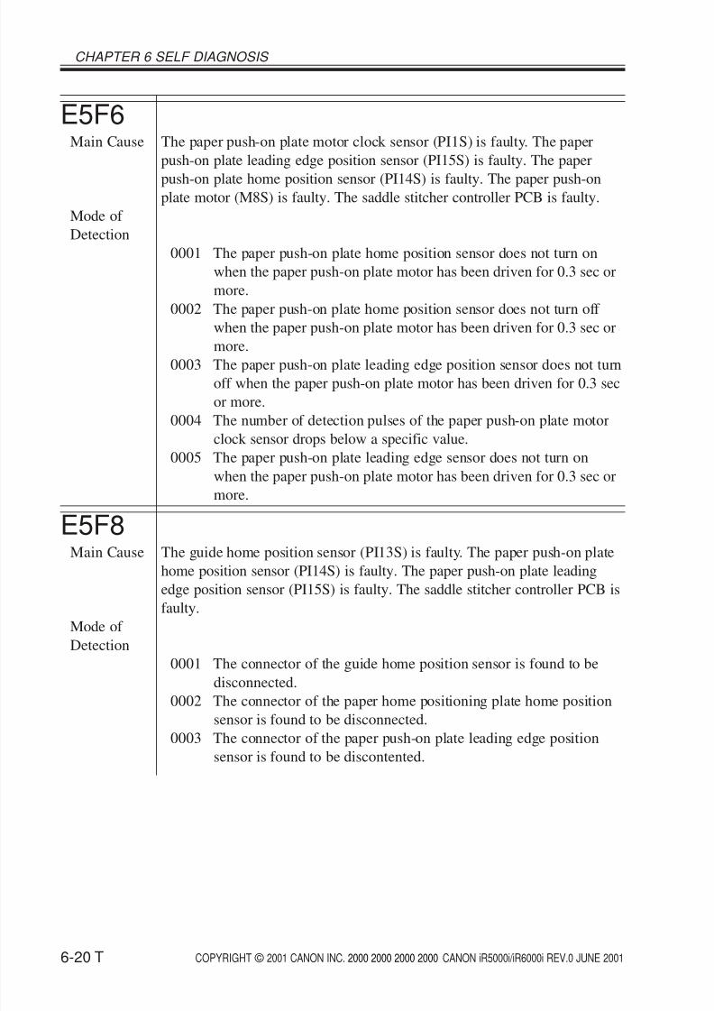
E5F6Main Cause The paper push-on plate motor clock sensor (PI1S) is faulty. The paper
push-on plate leading edge position sensor (PI15S) is faulty. The paper
push-on plate home position sensor (PI14S) is faulty. The paper push-onplate motor (M8S) is faulty. The saddle stitcher controller PCB is faulty.
Mode of
Detection
0001 The paper push-on plate home position sensor does not turn on
when the paper push-on plate motor has been driven for 0.3 sec or
more.
0002 The paper push-on plate home position sensor does not turn off
when the paper push-on plate motor has been driven for 0.3 sec or
more.
0003 The paper push-on plate leading edge position sensor does not turn
off when the paper push-on plate motor has been driven for 0.3 sec
or more.
0004 The number of detection pulses of the paper push-on plate motor
clock sensor drops below a specific value.
0005 The paper push-on plate leading edge sensor does not turn on
when the paper push-on plate motor has been driven for 0.3 sec or
more.
E5F8Main Cause The guide home position sensor (PI13S) is faulty. The paper push-on plate
home position sensor (PI14S) is faulty. The paper push-on plate leading
edge position sensor (PI15S) is faulty. The saddle stitcher controller PCB is
faulty.
Mode of
Detection
0001 The connector of the guide home position sensor is found to be
disconnected.
0002 The connector of the paper home positioning plate home positionsensor is found to be disconnected.
0003 The connector of the paper push-on plate leading edge position
sensor is found to be discontented.
8/6/2019 iR 6000i Code List
http://slidepdf.com/reader/full/ir-6000i-code-list 21/21
CHAPTER 6 SELF DIAGNOSIS
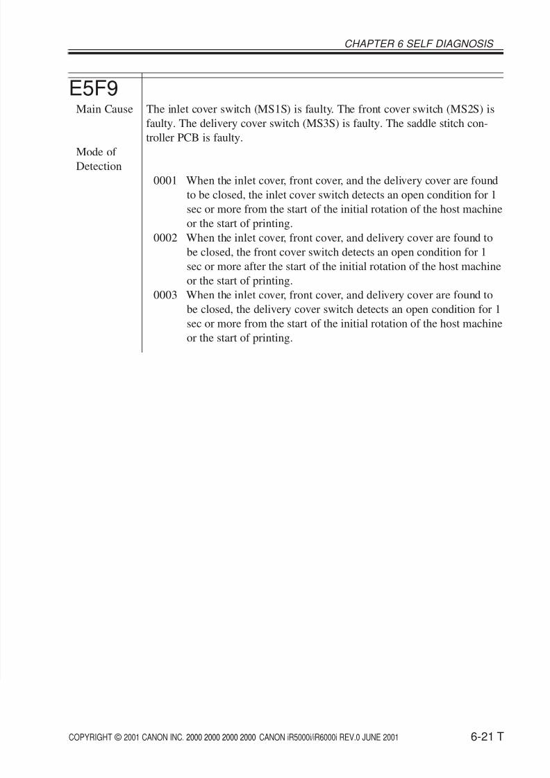
E5F9Main Cause The inlet cover switch (MS1S) is faulty. The front cover switch (MS2S) is
faulty. The delivery cover switch (MS3S) is faulty. The saddle stitch con-
troller PCB is faulty.Mode of
Detection
0001 When the inlet cover, front cover, and the delivery cover are found
to be closed, the inlet cover switch detects an open condition for 1
sec or more from the start of the initial rotation of the host machine
or the start of printing.
0002 When the inlet cover, front cover, and delivery cover are found to
be closed, the front cover switch detects an open condition for 1
sec or more after the start of the initial rotation of the host machine
or the start of printing.
0003 When the inlet cover, front cover, and delivery cover are found to
be closed, the delivery cover switch detects an open condition for 1
sec or more from the start of the initial rotation of the host machine
or the start of printing.