
io & m manual (pdf)
28
-
Upload
vuongnguyet -
Category
Documents
-
view
263 -
download
5
Transcript of io & m manual (pdf)


MULTI-STAGE CENTRIFUGAL BLOWERS & EXHAUSTERS
REV 092002-02US
page
1.0.0 GENERAL 11.1.1 Safety 11.2.1 Guarantee 11.3.1 Limit of liability 1
2.0.0 MACHINE ACCEPTANCE 2 2.1.1 Preliminary controls 22.2.1 Unloading and handling 22.2.2 Checks 22.3.1 Recommendations for lifting 22.4.1 Storage - short term 22.4.2 Storage - long term 2
3.0.0 STANDARD FITTING 33.1.1 Base-plate 33.2.1 Shock-absorbing support blocks 33.2.2 Leveling plates and fixing bolts 33.3.1 Direct drive using a coupling 43.3.2 Drive using pulleys and belts 53.3.3 Pulley/belt drive with additional support 53.3.4 Pulley/belt drive with countershaft 53.3.5 Drive using a gearbox 53.4.1 Coupling guard 53.4.2 Safety housing 53.5.1 Painting 5
4.0.0 SPECIAL APPLICATIONS 64.1.1 Machines for high temperatures 64.1.2 Machines for low temperatures 64.2.1 Gas machines 6
5.0.0 MOTORS 75.1.1 Electric motors 75.1.2 Star connection 75.1.3 Delta connection 85.1.4 Direct start-up 85.1.5 Star/delta start-up 85.1.6 Reduced voltage start-up 85.2.1 Turbines 85.3.1 Internal combustion engines 85.4.1 Hydraulic motors 8
6.0.0 TYPICAL FITTINGS 96.1.1 Flanged adaptor 96.2.1 Flexible sleeve 96.3.1 Expansion compensator 96.4.1 Butterfly valves - manual operation 96.4.2 Butterfly valve - pneumatic operation 96.4.3 Butterfly valve - electrical operation 106.5.1 Non-return valve 106.6.1 Intake filter - silencer filter 106.7.1 Silencers 106.8.1 Anti-surge valve 116.8.2 Anti-surge circuit 11
7.0.0 INSTRUMENTS 107.1.1 Ammeter 107.2.1 Capacity meter 107.3.1 Pressure gauge - vacuum gauge 107.4.1 Pressure regulator 117.5.1 Thermometer - thermostat 117.6.1 Pressurestat 117.7.1 Bearing temperature probes 117.8.1 Bearing vibration probes 11
page
8.0.0 INSTALLATION 128.1.1 Characteristics of the installation site 128.2.1 Fittings 128.3.1 Admissible static stresses on flanges 128.4.1 Piping 12
9.0.0 CONNECTIONS 139.1.1 Electricity supply 139.1.2 Steam 139.2.1 Lubrication system 139.3.1 Cooling water 139.4.1 Compressed air 139.5.1 Instrumentation 13
10.0.0 PERFORMANCES 1310.1.1 Operation as a turbo blower 1310.1.2 Operation as a turbo exhauster 1410.1.3 Mixed operation 1410.2.1 Surge limit 14
11.0.0 STARTING UP 1511.1.1 Preparation 1511.2.1 Checks 1511.3.1 Valve settings 1511.4.1 Direction of rotation 1611.5.1 Commissioning 16
12.0.0 MAINTENANCE 1612.1.1 Preventive maintenance 1612.2.1 Grease lubrication 1612.2.2 Oil lubrication 1712.3.1 Replacement of transmission belts 1912.4.1 Replacement of bearings 1912.5.1 Alignment and tension of transmission belts 2012.5.2 Alignment of transmission coupling 22
13.0.0 ANOMALIES: CAUSES AND REMEDIES 2413.1.1 Reduced performances 2413.2.1 Change in noise level 2413.3.1 Excessive supply or discharge temperature 2413.4.1 Excessive bearing temperature 2413.5.1 Excessive absorption 2413.6.1 High vibration level 24
14.0.0 SPARE PARTS 2514.1.1 Recommended set 2514.2.1 Consumables 2514.3.1 Ordering 25
15.0.0 ASSISTANCE 2615.1.1 On-site repairs 2615.2.1 Repairs in our workshops 26
1.0.0 GENERALLY
0-26
CONTENTS
MULTI-STAGE CENTRIFUGAL BLOWERS & EXHAUSTERS
REV 092002-02US
CONTINENTAL turbo blowers and turbo exhausters aremade in accordance with current safety regulations.
The various production phases undergo the checks provi-ded for by the quality control plan to ensure that mate-rials and assembly are free from defects. A11 machinesare mechanically tested before dispatch.
1. 1. 1 Safety
Common sense must be used and general safety stan-dards together with any special standards for the speci-fic installation must be strictly observed when moving,installing, using and handling machinery. No operationor maneuver shall be carried out by inadequately quali-fied personnel.
In particular, the following are not permitted:
- the use of cables or eye-bolts which are damaged orhave inadequate characteristics for lifting
- working on high-voltage electrical components if notspecifically qualified for such work
- working on live electrical circuits or in the presence ofcharged capacitors
- working on machines connected to an electricity supplywithout having switched off the isolator or put outappropriate "works in progress" signs
- assuming that the precautions taken are definitely ade-quate and that checks do not need to be made, forexample, where work is resumed after a halt
- operating machines with coupling or bearing housingguards removed
- operating machines with the inlet opening uncovered
- leaving machines in operation unsupervised in the pre-sence of children or animals
- approaching rotating parts wearing ties or shirts.
1.2.1 Guarantee
CONTINENTAL turbo blowers and turbo exhausters,unless otherwise specified when ordering, are guaran-teed for twelve months from their start-up, but for nomore than eighteen months from their date of deliveryto the original purchaser.
During this period, CONTINENTAL will replace or repairany part free of charge, free own works, provided thatthe tests made reveal material or manufacturing defects.To make a claim under guarantee, the machines and/orsystems must have been used for their intended applica-tion and in compliance with CONTINENTAL's instructions.
The purchaser loses all guarantee rights if the machinesand/or systems are repaired or modified, in whole or inpart, by the purchaser or third parties, unless this hasbeen agreed in writing by CONTINENTAL, who howeverdo not accept any liability for the repair or modificationthus authorized.
Transport expenses, including insurance costs, for thedefective parts to and from CONTINENTAL's works willbe borne by the purchaser.The guarantee does not cover damage resulting fromincorrect use (operation in unstable conditions, at
inadmissible speeds of rotation, at inadmissiblepressures or temperatures etc.), negligence, alterationsand incidents.
Materials and/or components, such as motors, valves,gearboxes, electrical equipment etc. bought byCONTINENTAL from third parties are guaranteed bytheir respective suppliers and these guarantees aremaintained in accordance with the above conditions.
CONTINENTAL reserves the right to invoice all replace-ments made due to material or manufacturing defectswhere repairs are carried out on site at the specificrequest of the customer.
1.3.1 Limit of liability
CONTINENTAL's liability in respect of claims of any kind,including negligence, consequential or associated loss ordamage, or loss or damage resulting from theperformance, design, manufacture, operation, use andlikewise from any installation, technical installationinstructions, inspection, maintenance or repair of anymachine and/or system supplied, will not under anycircumstances exceed the purchase price of the machineand/or system giving rise to that claim and ends atexpiry of the guarantee period defined in item 1.2.1.
Under no circumstances, whether due to breach of theguarantee by CONTINENTAL or by manifest negligence,shall CONTINENTAL be responsible for special and conse-quential damages including, without this list beingexhaustive, losses of profits or proceeds, loss of use ofthe machines and/or systems themselves or connectedmachinery, capital cost, cost of replacement machinesand/or systems, tooling or services, costs for down timeor customers' claims to the purchaser for such damages.
Unless expressly stated in writing, the machines produ-ced by CONTINENTAL are not intended for use in nuclearsystems or activities.
CONTINENTAL refuses any liability for any damages,injuries and nuclear pollution which may occur as aconsequence of such unauthorized use and thecustomer shall indemnify CONTINENTAL for any claimsderiving therefrom, including any attributedto negligence.
1-26
MULTI-STAGE CENTRIFUGAL BLOWERS & EXHAUSTERS
REV 092002-02US
2.0.0 MACHINE ACCEPTANCE
2.1.1 Preliminary controls
When machinery is taken directly from the works orfrom a carrier's depot or when it is delivered by a carrier,the delivery and/or dispatch documents must first bechecked to ensure that the equipment ordered has beenreceived.
All packs comprising the supply, unless otherwisespecified when ordering, are marked with theCONTINENTAL order number.
The packaging or the equipment itself, if it is visible,must be checked for any obvious signs of damage incur-red during handling and transport. If such damage isfound, this evidence must be put directly to the carrierand it must be ensured that the carrier notes this clearlyon the delivery document before signing it. CONTINEN-TAL must also be informed promptly to avoid any disa-greement and to guarantee rapid and satisfactory sett-lement of any damages.
2.2.1 Unloading and handling
The addressee is responsible and liable for unloadingoperations and shall therefore entrust supervision the-reof to appropriately qualified personnel, selected onthe basis of the size of the machinery and the difficultypresented by the operation.
2.2.2 Checks
A check shall be made promptly that all the equipmentreceived corresponds to the order and any irregularitiesshall be advised to CONTINENTAL immediately for thenecessary corrective action.
It is recommended in particular that the presence of allthe fittings ordered and the supply voltage of any elec-tric motors be checked.
2.3.1 Recommendations for lifting
In view of the number of models produced byCONTINENTAL and the special features possible for eachindividual order, there is a vast number of feasible casesand nothing therefore can replace the experience ofpersonnel in the handling of machinery in general.
The sole recommendation is never to use bearinghousings for the fixing of slings.
Where necessary, specific instructions for lifting andhandling are provided separately.
2.4.1 Storage - short term
If a period of machine inactivity of not more than 60days is planned, no particular precautions are requiredfor storage. The protective devices provided directly byCONTINENTAL before its dispatch from the works arethus sufficient to keep it in good condition for this per-iod, provided that it is kept under cover in a clean anddry environment and without the covers on the inletand outlet openings being removed.
2.4.2 Storage - long term
For periods of inactivity of over 60 days, in addition tokeeping the machinery under cover and in a clean anddry environment, the following precautions must alsobe taken:
- check that the inlet and outlet openings are properlysealed
- slacken any transmission belts
- fill any oil-lubricated bearing housings in accordancewith the instructions given in item 12.2.2 - frequentlycheck the condition of machined and unpainted surfaces(shaft ends, bearing services etc.) making good, wherenecessary, the protective coating provided in the works
- approximately every 30 days, rotate the machine andmotor shafts manually for a few revolutions.
During storage, it is essential to prevent the machinebeing subject to vibrations produced by the operation ofnearby machines and propagated via the bearing sur-faces. Such vibrations applied for long periods coulddamage the machine and motor bearings.
It is also necessary to prevent the machine from beingsubject to frequent and/or sudden changes intemperature causing the formation of condensation,especially inside machines and motors and insidebearing housings. Where the possibility of condensationcan be foreseen, the following shall be carried out:
- hang a bag of silica gel or another hygroscopicsubstance inside the inlet opening and inside the outletopening, immediately replacing the respectiveprotective covers
- place a bag of silica gel or another hygroscopicsubstance for the openings on every bearing housing
- isolate the machinery from the ambient atmosphere, ifpossible using sealed impermeable bags or using imper-meable covers carefully placed to minimize air circulation.
2-26

MULTI-STAGE CENTRIFUGAL BLOWERS & EXHAUSTERS
REV 092002-02US
3.0.0 STANDARD FITTING
The typical fittings for CONTINENTAL turbo blowers andturbo exhausters include a base-plate common to themachine and the motor, a series of foundation fixings,the machine/motor coupling and the protective guardover the coupling.
3.1.1 Base-plate
Small machines are generally given an OMEGA base-plate made of pressed steel plate strengthened withappropriate reinforcements - Fig. 3.1.
Other machines, in contrast, have an electro-weldedsteel section base-plate - Fig. 3.2.
All the base-plates have screws to align the motor andtighten any transmission belts. The base-plates must belevel if the machine is to work correctly.
This should be checked with particular care in oil lubri-cated machines.
Fig. 3.1 Fig. 3.2
3.2.1 Shock-absorbing support blocks
CONTINENTAL machines can be installed by placing theshock-absorbing blocks included in the supply betweenthe base-plate and the bearing surface - Fig. 3.3.
The type and the quantity of blocks required is definedby CONTINENTAL on the basis of machine characteristics.The shock-absorbing support blocks enable the machineto be installed easily and rapidly without the need tomake specific foundations.This allows the machine to be connected while preven-ting the transmission to the surrounding environment ofvibrations generated by it and likewise the transmissionto the machine of any vibrations present in the surroun-ding environment.
If the machine is to operate correctly, all the shock-absorbing support blocks must be loaded uniformly.At installation, it is therefore necessary to check thatnone of the shock absorbers has been left unloaded.
Irregularity in the bearing surface and the dimensionaltolerances of the base-plate and the shock absorbersthemselves almost always mean that corrections need tobe made by placing shims between the shock absorberbase and the bearing surface.
3.2.2 Levelling plates and fixing bolts
Fixing bolts and levelling plates can be provided insteadof shock-absorbing support blocks.
The use of anchor bolts, more usual for machinery withhigher installed power, involves the making of a plinthisolated from the rest of the foundations to prevent thetransmission of vibrations.
Where anchor bolts are used, the base-plate shall befitted in accordance with the following instructions:
1 - Make the plinth, if possible keeping it isolated fromthe rest of the foundation.The upper surface shall be left rough so as to provide agood key with the grouting to be carried out subsequently.
2 - Raise the base-plate to approximately one meterabove the plinth.Fit the levelling screws and the anchor bolts as shown indetail A of Fig. 3.4.Check the 15 mm and 50 mm overhangs indicated.
3 - Lower the base-plate to approximately 200 mm fromthe plinth, centering the anchor bolts in the pockets.Position the 100 x 100 x 20 plates under the levelling screws.Lower until the levelling screws come into contact withthe plates.Position the base-plate in its final location, longitudinallyand transversally.Center the plates under the levelling screws.Wedge the plates which are not in contact with theadjustment screws.Do not use the screws to make contact with the plates.
4 - Check that the anchor bolts are positioned correctlyin the pockets.Cement the anchor bolts into their pockets. Leave toharden as appropriate.
5 - Loosen all the locknuts of the anchor bolts andlevelling screws. Slightly tension using the anchor boltnuts and the levelling screws.
6 - Check that the base-plate is level by using a spirit levelsensitive to 0.0,2 mm/m.This check shall be made longitudinally and transversally onall finished surfaces.It shall be level to 0.02 mm/m.It is adjusted by using the spirit level on the finished sur-
3-26
A = drill hole for fixing to base-plateB = drill holes for fixing to bearing surfaces using
expansion bolts

MULTI-STAGE CENTRIFUGAL BLOWERS & EXHAUSTERS
REV 092002-02US
face as shown in detail B of Fig. 3.4 and using the level-ling screw/anchor bolt sets.Each levelling screw/anchor bolt set can be used to raiseor lower the base-plate and therefore the edge of thefinished surface relative to the adjacent one.
Fig. 3.4
In particular:
- for lowering, the levelling screw must be slackenedand the anchor bolt nut tightened- for raising, the anchor bolt nut must be slackened andthe levelling screw tightened.
7 - When all surfaces are levelled transversally and lon-gitudinally as specified, ensure that no screws or nutsare slack. If any are, they must be tightened manually soas not to disturb the level obtained.
All lock nuts are also to be tightened manually.
8 - Clean the surfaces of the plinth and prepare it forgrouting. Provide an enclosure as shown in detail C ofFig. 3.4. If it is being installed in the open air, provideappropriate drainage for rainwater, taking account ofthe base-plate shape.
Pour grout under the base to the level indicated indetail C of Fig. 3.4. Avoid the use of mechanical vibratorsso as not to disturb the level surface obtained. Instead,promote grout penetration with bars or chains.
9 - Cure the cement adequately for an appropriate num-ber of days.
10 - Tighten all the anchor bolt nuts and the associatedlock nuts before fitting the machines.
3.3.1 Direct transmission using a coupling
Direct drive to the motor with a coupling is used wherethe speed of rotation of the machine is the same as thatof the motor.This is the case particularly with machines driven by 60Hz electrical motors and for turbine-driven machines.The couplings commonly used are of the geared orlamellar type.A spacer is always fitted to enable the bearing at thecoupling end to be replaced without disturbing the alignment.
IMPORTANT: All gear-type couplings must be grease-lubricated.
Machines fitted with gear-type couplings at the factoryare already greased and ready for use.On the other hand, where the gear-type coupling is fit-ted by the client, the spaces between the teeth of thetwo hubs and the two sleeves must be completely filledwith grease.In models with holes for lubrication, once assembly isfinished, the coupling must be completely filled by injec-ting grease under pressure until this escapes from theopposite hole.
4-26
BASE PLATEMETHOD OF LEVELLING AND ANCHORING
WITH ANCHOR BOLTS
LEVELLINGWEDGE
CASTING UP TO
THIS LEVEL
ENCLOSURE
ISOLATOR
LEVELLING
SCREWS
LOCK NUTS
ANCHOR
BOLT
SPIRIT LEVEL
SENSITIVITY 0,02 mm/m
FINISHED
SURFACE
DETAIL ADETAIL B
DETAIL A

MULTI-STAGE CENTRIFUGAL BLOWERS & EXHAUSTERS
REV 092002-02US
The coupling is lubricated in the same way, at intervalswhich are multiples of those set for bearing lubrication.As the lubricating power of the grease diminishes over aperiod of time, due to the effect of mechanical stresses,ageing and pollution (possible regardless of the presenceof gaskets), the regular replacement of all the grease inthe coupling is recommended.With regard to the alignment of the transmission cou-pling, refer to item 12.5.2.
3.3.2 Transmission using pulleys and belts
Pulley and belt couplings are widely used as they enable abetter speed of rotation to be selected and the machinecan therefore be used close to the point of top output.In many cases, it also allows 4-pole motors to be used toreduce the overall noise level of the unit and also enablesthe throttle curve of the machine to be changed to a cer-tain extent by the simple replacement of the pulleys.With regard to the alignment and tensioning of the trans-mission belts, refer to item 12.5.1.
3.3.3 Pulley/belt transmission with additional support
Where the tension of the belts on the machine bearingneeds to be reduced, an additional support and a thirdbearing can be used.This support is provided by a housing connected by screwsto a wide flange which bolts onto the blower outlet head- Fig. 3.5.The replacement of transmission belts, which must be car-ried out in accordance with the general instructions givenin item 12.3.1, involves the removal of the housing.With regard to the alignment and tensioning of the trans-mission belts, refer to item 12.5.1.The belts shall be put under tension only when the hou-sing has been refitted.
3.3.4 Pulley/belt transmission with countershaft
Where high belt tension is required for power transmis-sion, a countershaft is used which enables the tension tobe accepted totally on its supports.The connection between the machine and the counter-shaft is therefore made with a coupling, as described initem 3.3.1.The transmission belts shall be aligned and tightenedusing only the motor in accordance with the general ins-tructions given in item 12.5.1.The transmission coupling shall be aligned using only themachine in accordance with the general instructions givenin item 12.5.2.Transmission belts shall be replaced in accordance with thegeneral instructions given in item 12.3.1 but takingaccount of the fact that, in this case, the countershaftneeds to be removed.For rapid re-positioning of the shaft supports, the use of theadjusting screws provided for this purpose is recommended.
Whenever the transmission belts are replaced, it is alsorecommended that the coupling alignment be checked.
3.3.5 Transmission using a gearbox
Where the speed of rotation of the machine is greaterthan the speed of rotation of the motor and the value ofthe power to be transmitted does not allow for the use ofbelts, a gearbox is used.Gearboxes with parallel shafts and helical or double heli-cal gears are normally used.Motor/slow shaft and fast shaft/machine connections aremade with couplings as described in item 3.3.1.The gearbox is fitted directly on one of the structural sup-ports with the machined surfaces between the motor andthe blower.Its position with regard to the base-plate is fixed and thusno screws are provided for its alignment. There are some-times two dowels for re-positioning the gearbox if it isremoved.It is aligned only by moving the machine and motor inlateral and longitudinal directions using the appropriatescrews.Any height correction is made by changing the settings ofthe shims under the feet of the blower and the motor. Thevalues of the distances to be kept between the shaft endsand the alignment tolerances, hot and cold, for the fast cou-pling and for the slow coupling are provided separately.The use of a gearbox requires a forced lubrication circuitand cooling of the lubricating oil, generally achieved usinga water/oil heat exchanger.This also includes a safety system which provides an alarmsignal and a shut-off signal if the lubricating oil pressure istoo low.The lubricating oil is generally held in the housing of thegearbox itself and is circulated by a gear pump driven bythe slow shaft.There is sometimes a separate lubricating unit which comprisesa tank, any auxiliary and spare electrical pump required, theheat exchanger, the pressure accumulator etc.Where necessary, specific instructions are provided separa-tely for the use and the maintenance of the gearbox.With regard to the alignment of the transmission cou-plings, refer to item 12.5.2.
3.4.1 Coupling guard
The coupling guard, whether for a direct coupling or abelt coupling, is made of steel or aluminum sheet andfixed using stirrup screws generally welded to the base-plate. Given the variety of shapes and dimensions possible,specific instructions cannot be given for removal, althoughthis does not present any difficulty to the maintenancepersonnel.
3.4.2 Safety housing
In some cases (for example, biogas turbo blowers), themachine is fitted with a housing comprising two steelsheet half shells, held together with screws and nuts,which do not enclose the body.All normal maintenance can be carried out without theneed to remove it.
3.5.1 Painting
The standard painting of CONTINENTAL turbo blowersand turbo exhausters and their common accessoriesconsists of a base coat applied after brushing and degrea-sing and a finishing coat in hammer finish grey, syntheticenamel RAL 7005.
5-26

MULTI-STAGE CENTRIFUGAL BLOWERS & EXHAUSTERS
REV 092002-02US
4.0.0 SPECIAL APPLICATIONS
Machines can be supplied to specifications to meet thespecific needs of certain individual applications.
4.1.1 Machines for high temperatures
Where machines are to operate at a high temperature,the following measures can be taken in addition to pos-sible deviations from standard models with regard totolerances and the materials for certain items:
- screens and/or spacers to reduce the heat transmittedto the bearings via the housings
- water-cooling circuit for bearings
- facility for sliding the outlet head feet in a longitudinaldirection.
Where necessary, specific instructions will be providedseparately with regard to the above features and thelubricants to be used.
4.1.2 Machines for low temperatures
Where machines are to operate at low temperatures,the following measures can be taken in addition to pos-sible deviations from standard models with regard tothe materials for certain items:- circuit to preheat bearings before start-up.Where necessary, specific instructions will be providedseparately with regard to the above features and thelubricants to be used.
4.2.1 Gas machines
Where the fluid processed is a gas other than air, variousmeasures can be adopted depending on the particularcharacteristics of the application and the gas itself:
- the inside of the machine body can be given agas-proofing treatment to prevent gas losses to theenvironment via casting pores
- fitting of the machine safety housing described in item 3.4.2
- use of special belts and/or transmission couplings forthe spark-proof models
- use of special coupling guards for the sparkproof models
- mechanical shaft sealing to minimize losses of the gasprocessed into the environment
- sealing of the shaft by injection of the same gasprocessed to prevent contamination of the gas byatmospheric air
- sealing of the shaft by the injection of inert gases toprevent losses of the gas processed into the environment
- use of special materials for rotors and/or the shaft
- use of protective coatings for rotors and/or the machinebody interior.
- Where necessary, specific instructions are providedseparately with regard to the above features.
5.0.0 MOTORS
The mechanical energy required to run CONTINENTALturbo blowers and turbo exhausters is taken from amotor.
In most cases electric motors are used, but other types ofmotor can also be used.
5.1.1 Electric motors
IMPORTANT: all work on high-voltage electric motorsmust be carried out only by qualified personnel.
All electric motors must be individually earthed using anappropriately sized mains cable.The electric motors commonly used run on three-phasealternating current.
In electric motors, the only parts subject to wear are thetwo bearings which support the rotor and which arenormally grease-lubricated. Depending on the size,there can be two ball bearings or one ball bearing andone cylindrical roller bearing. Lubrication periods andthe quantities and type of grease to be used for the bea-rings are usually given on the motor plate.Refer to items 12.1.1 and 12.2.1 of this manual withregard to the lubrication and preventive maintenance ofbearings.Large motors can be fitted with plain bearings for whichspecific maintenance instructions are provided separately.The windings of electric motors lead to 6 terminals in aterminal box which has holes for the passage of powercables. The terminal box is located on the top or to oneside of the motor.Often terminal boxes located on the top of motors canbe orientated at 90 increments.The terminals are arranged and designated as illustratedin figures 5.1 and 5.2.In some cases, there can also be terminals to connectspecial devices such as anti-condensation resistance(heaters) or platinum probes to measure the temperatu-re of the windings.The main characteristic data is stamped on a metal platefitted on every motor.Motors must always be connected down line from sui-table protection against short circuits and overloads.Not all motors are designed to operate in either direc-tion of rotation. Often the cooling fan blades are orien-tated to be more efficient and cause less noise.
Fig. 5.1 Fig. 5.2
5.1 2 Star connection
The star connection is used where the line voltage is thesame as the higher of the two voltages given on theplate (the line voltage is the potential difference bet-ween two of the three conductors R, S and T).
The three links fitted in the terminal box must be set outas shown in Fig. 5.1.
6-26
STAR CONNECTION DELTA CONNECTION
MULTI-STAGE CENTRIFUGAL BLOWERS & EXHAUSTERS
REV 092002-02US
At the first start-up, the direction of rotation mustalways be checked as, if necessary, it can be reversedquite simply by swapping two of the three supply cablesR, S and T.
5.1.3 Delta connection
The delta connection is used where the line voltage isthe same as the lower of the two voltages given on theplate (the line voltage is the potential difference bet-ween two of the three conductors R, S and T).The three plates fitted in the motor must be set out asshown in Fig. 5.2 (two overlap).At the first start-up, the direction of rotation mustalways be checked as, if necessary, it can be reversedquite simply by swapping two of the three supply cablesR, S and T.
5.1.4 Direct start-up
Apart from factors regarding the electricity supply line,there are no objections to a direct start-up of electricmotors coupled to CONTINENTAL turbo blowers andturbo exhausters.Direct start-up consists of powering the motor directly atnormal operating voltage.This allows the motor to develop the maximum accele-ration torque and thus to reduce to a minimum the timerequired to reach the nominal speed of rotation.Naturally, maximum current absorption corresponds tothe maximum acceleration torque.
5 1.5 Star/delta start-up
To reduce the load on the supply line and to contain theabsorption "peaks", star/delta start-up is sometimesused, but only for power over 7.5 kW.The star/delta start-up consists of powering the motor ata voltage lower than that of its normal operation untilits speed of rotation is close to nominal (a few seconds)and then moving to a full voltage supply.This is possible only where the line voltage is the lowerof the two voltages given on the plate (the line voltageis the potential difference between two of the threeconductors R, S and T).
In the first mode, the motor has a star connection andtherefore the line voltage is 1.73 times lower than itsnominal supply voltage. The current absorption and theacceleration torque are approximately one third of theirmaximum value and therefore the time required toreach values close to the nominal speed of rotation islonger than with direct start-up.
In the second mode, the motor has a delta connectionand therefore the line voltage is equal to the nominalsupply voltage. Absorption and acceleration torque maynow reach their maximum values but the machine isalready close to its nominal speed of rotation andrequires only a small final acceleration.
The star/delta start-up involves the movement of theterminal box links and the connection of six separatecables, one for each terminal.To reverse the direction of rotation, two of the threecables connected to one side of the terminal box andthe two opposite cables on the other side of the termi-nal box must be swapped.
In view of the relatively long start-up times typical formultistage centrifugal blowers and exhausters, the useof thermal protection is recommended in the controlpanel.
5.1.6 Reduced voltage start-up
Reduced voltage start-up is basically the same as thestar/delta start-up described in item 5.1.5 with the diffe-rence that the delta-connection motor, is powered inthe two modes at two different voltages; the lower ofthem is generally obtained by means of an auto-trans-former.
5.2.1 Turbines
Direct turbine coupling is generally used because of thespecific characteristics of the installation. The special ins-tructions required are provided separately.
5.3.1 Internal combustion engines
The use of internal combustion engines is generally res-tricted to machines installed on self-propelled equip-ment and machines in fixed installations where thereare plenty of natural or biological gases.A clutch is inserted between the motor and the trans-mission which can be made by belts and pulleys or by agearbox.The special instructions required are provided separately.
5.4.1 Hydraulic motors
The use of hydraulic motors is generally restricted tomachines installed on self-propelled equipment.
The hydraulic motor is supplied with pressurized oil bythe main motor of the equipment itself.Transmission is usually by means of belts and pulleys.The special instructions required are provided separately.
7-26

MULTI-STAGE CENTRIFUGAL BLOWERS & EXHAUSTERS
REV 092002-02US
6 0.0 TYPICAL FITTINGS
Depending on the application for which CONTINENTALturbo blowers and turbo exhausters are intended, theycan be provided with certain fittings to enhance theinstallation and enable it to be used correctly.As the machine ports must not be stressed with forcesand/or moments greater than limits depending on theirsize, it may be necessary to provide for the support ofcertain fittings.The values of the static stresses admissible on theopenings are given in item 8.3.1.
6.1.1 Flanged adaptor
The flanged adaptor, comprising a piece of tube weldedto a mating flange, is used together with a flexible slee-ve to connect the inlet and/or outlet port to the pipingof the system to be served.The connection thus made prevents the transmission ofvibrations from and to the machine and enables thermalexpansion to be absorbed.The fittings and the pipes connected above the adaptermust be appropriately fixed so that they do not rest onthe adapter itself.
6.2.1 Flexible sleeve
The flexible sleeve (fig 6.1), made of reinforced rubber,is intended for fitting with the flanged adaptor descri-bed in item 6.1.1.The flexible sleeve is secured to both the tubes connec-ted by two straps.
Fig 6.1
6.3.1 Expansion compensator
For working temperatures of up to 110°, the expansioncompensator is made of reinforced rubber with anomega section; for higher temperatures, the use of astainless steel compensator is preferred.(See fig 6.2)
It is for connecting the ports of the machine to pipesand/or flanged fittings.
The compensator enables thermal expansion to beabsorbed and prevents the transmission of vibrationsfrom and to the machine. The fittings and the pipeslinked above the compensator must be appropriatelyfixed so that they do not rest on the joint itself.
Fig 6.2
6.4.1 Butterfly valves - manual operation
A butterfly valve is generally found in all installations tocut the machine off from the system and/or to control itsoperation.In most installations, it is preferable to fit the valvedirectly on the inlet opening; however, specific instruc-tions on controlling operation by means of the butterflyvalve are found in item 10.1.1."Wafer" type butterfly valves can be fitted directly onthe machine ports before the flanged adaptor or theexpansion compensator.
Generally, valves have an operating lever lock system.
6.4.2 Butterfly valve - pneumatic operation
This valve has the same function as that described initem 6.4.1 but is operated by compressed air.It can also be used as an overflow valve in anti-surge systems.Valves intended for on-off operation generally haveservocontrols with a double-acting cylinder powered bya solenoid valve.The compressed air supplied must have a pressure of bet-ween 5 and 8 bars and must be filtered and lubricated.Operating speed can be controlled directly using thethrottles on solenoid valve discharges. There may beadjustable mechanical limits for fixing the maximumopen and/or maximum closed positions of the butterfly.
There may be SPDT end-of-run contacts, which can bepositioned with mechanical limits, for use in the startupsequence or for other controls and/or signals.Valves intended for regulation have servocontrols whichare single- or double-acting with a positioner.In addition to the compressed air supply, these alsorequire an adjustment signal, range 3 - 15 psi (0.2 - 1 bar).
There are also pneumatic drives which require electricalregulation signals, range 4 - 20 mA or 0 to 20 V.
Where necessary, specific instructions are provided separately.
8-26
Expansion compensatormade in reinforced
rubber
Expansion compensatormade in stainless steel

MULTI-STAGE CENTRIFUGAL BLOWERS & EXHAUSTERS
REV 092002-02US
6.4.3 Butterfly valve - electrical operation
This valve has the same function as that described initem 6.4.1 but is operated using an electric motor.It can also be used as an overflow valve in anti-surge systems.Its operating speed is fixed.The maximum open and maximum closed positions canbe controlled using two end-of-run contacts.The valve is suitable both for on-off operation and forregulation. Naturally, where used for regulation, thesignal from the system must be processed by a suitableelectric circuit. Where necessary, specific instructions are provided separately.
6.5.1 Non-return or check valve
The check valve is used wherever the return of the gasprocessed needs to be prevented.The most common case is where two or more turboblowers or two or more turbo exhausters are connectedin parallel.
A very common non-return valve comprises a disc fixedto the body at a single point on its circumference. Thismust always be fitted with a vertical axis and so as toremain normally closed due to the effect of the force ofgravity alone. Therefore, this valve must always be fittedon the process side of both turbo blowers and turboexhausters. (fig 6.3)
Another type of non-return valve comprises two flapsfitted diametrically on to the body and loaded with twosprings which keep them closed in any position. Thereare therefore no restrictions with regard to its fitting.
"Wafer" body non-return valves can be fitted directly onthe machine ports before the flanged adaptor or theexpansion compensator.
Fig 6.3
6.6.1 Inlet filter - silencer filter
The inlet filter is for use with air. The standard filtercomprises a flanged body which has a structure forsupporting and fixing the filtering elements.
Depending on the size of the turbo blower and itscapacity, the filter can take one to six filtering elements.The dry filtering element is a cylindrical cartridge madeof inert material which includes one fitting at each endsuch that they can be placed on top of each other.
Each cartridge or pair of cartridges is fixed to the filterusing a central rod, a disc and a wing nut.
Depending on the nature of the pollutant, it is possibleto clean the cartridge with varying degrees of ease.Clean as normal with a jet of compressed air or wash inwater with detergent and rinse thoroughly. It is impor-tant to wait until the cartridge is perfectly dry before re-using it.Filtering elements need to be cleaned or replaced whentheir pressure drop reaches a value of 80 - 100 mm H2O.The inlet filter can be fitted with a protective cover forinstallation in the open air. The cover must be removedfor maintenance.
The filter silencer has a sound-absorbent cover whichmust be removed for maintenance.
Inlet filters must be fitted where there is easy access forinspection and maintenance. It may be necessary to pro-vide appropriate service platforms.
For non-standard inlet filters, specific instructions areprovided separately where necessary.
6.7.1 Silencers
IMPORTANT: An arrow on the silencer body indicates that the flow isone-directional and that the silencer must be placed inthe right direction.
The inlet, the outlet and any overflow valves are themajor sources of noise in the machine.
The purpose of the silencer is to attenuate the propaga-tion of this noise into the atmosphere.Absorption, full flow or annular silencers and low pres-sure drop silencers are generally used on inlet and out-let or discharge lines.On overflow lines, in certain special cases, combinedtype silencers may be preferred.The silencing of the inlet line must be given priority forturbo blowers as it is in direct communication with theatmosphere.For the same reason, the silencing of the discharge linemust be given priority in turbo exhausters.Inlet and outlet or discharge silencers must be isolatedfrom the machine by expansion joints or flexible sleevesand must be fixed with suitable brackets. These must befitted as close as possible to the respective openings.Flanged silencers are often used at one end with aflexible sleeve and a flanged adaptor at the other.These must be fitted with the flexible sleeve nearer tothe machine opening.Silencers on overflows to the atmosphere used in theanti-surge circuit of turbo blowers must be fitted asclose as possible to the overflow valve.If a piece of pipe needs to be fitted to connect the over-flow valve and the silencer, the use of very thick pipe isrecommended.At the end of the discharge, silencers on overflows tothe atmosphere must have a fluted curve and a protec-tive wire mesh.Overflow silencers used in the anti-surge circuit of turboexhausters must be fitted as close as possible to theoverflow valve.If a piece of pipe needs to be fitted to connect the over-flow valve and the silencer, the use of very thick pipe isrecommended.At the end of the inlet, overflow silencers for turboexhausters must have a filter and, if installed in the openair, they must be protected from rain.
9-26
CHECK VALVE SINGLE FLAP
CHECK VALVE DOUBLE FLAP
MULTI-STAGE CENTRIFUGAL BLOWERS & EXHAUSTERS
REV 092002-02US
6.8.1 Anti-surge valve
Where the fluid processed is air and where system cha-racteristics so allow, the anti-surge valve can be used toprevent the machine operating at capacities lower thanthe minimum admissible, to prevent surge coming intooperation.In turbo blowers, the valve must be fitted immediatelydown line from the outlet opening to allow air to bedischarged into the atmosphere.In turbo exhausters, the valve must be fitted immedia-tely up line from the inlet opening to allow air to betaken directly from the atmosphere.
IMPORTANT: In some cases, the efficiency of the antisurge valve canbe impeded by the operation of the cutoff/regulationbutterfly valve fitted at the machine inlet.
The anti-surge valve prevents the machine operating atpressures/negative pressures greater than the designpressure and thus prevents the capacity falling corres-pondingly.
The valve must be calibrated in the field. Calibration iscarried out as follows:
- start up the system and run at its nominal capacity
- gradually reduce the capacity so that it starts surging(surging is identified by a characteristic pulsing noiseand can be confirmed by the movement of the needle ofan ammeter connected to the machine's electric motor)
- use the tare nut of the valve spring to obtain sufficientopening to start surging
- continue alternating between reducing the capacity andadjusting the tension of the spring until the surging stops.
6 8.2 Anti-surge circuit
Where the specific characteristics of the system (forexample, operation at constant pressure) do not allowthe use of the anti-surge valve described in item 6.8.1,an anti-surge circuit can be used.An anti-surge circuit is also often used in the start-upsequence of medium and large machines.Some anti-surge circuits operate on the basis of currentabsorption from the electric motor: the circuit preventsthe operation of the machine below a minimum currentabsorption value which can be set using an appropriateelectrical circuit.Other anti-surge circuits operate on the basis of theactual measurement of the flow rate processed.
Where necessary, specific instructions are providedseparately.
7.0.0 INSTRUMENTS
CONTINENTAL turbo blowers and turbo exhausters canbe connected to instruments to display some of the ope-rating parameters and also to provide signals used forregulation and/or alarms and cut-off in the case ofbreakdown.
7.1.1 Ammeter
This is installed mainly to have an approximate indica-tion of the capacity of the machine driven by the electricmotor.
The change in the current absorbed by the electricmotor is directly proportional to the capacity handled bythe machine .
Using any minimum and maximum adjustable contactsin the ammeter, it is possible to obtain signals at surgelimit and maximum load operation.
These signals can be used in alarm and cut-off or regu-lation circuits.
The ammeter transformer can be fitted to any of thethree supply conductors. Where there is a star/deltamotor, the transformer can be connected to one of thethree conductors, up line from the motor, or to a pair ofconductors down line from the motor, more precisely toa conductor at the outlet of the delta contactor connec-ted to that phase.
To prevent damage to the instrument, the ammetermust be shunted during the start-up mode.However, normally ammeters can be found with a loga-rithmic scale able to tolerate any peak currents.
7.2.1 Capacity meter
In some processes, it is necessary to have an accuratemeasurement of the volume processed by the machinein order to regulate its performance.
Volume measurements are generally obtained from thevalue of the differential pressure generated via Pitottubes (Annubar), Venturi tubes or calibrated dia-phragms. In order to control regulation devices, thesignal received from one of the above items must beprocessed and possibly compensated via an appropriatepneumatic, electronic or mixed circuit.
7.3.1 Pressure gauge - vacuum gauge
The pressure gauge can be used to determine the valueof pressure generated by a turboblower.
If fitted immediately down line from the outlet opening,it provides the total value of pressure produced by thepassage of the air flow into the system served down linefrom the machine.
The vacuum meter is used to find the value of the nega-tive pressure developed by a turbo exhauster.
If fitted immediately up line from the inlet opening, itgives the total value of vacuum produced by the passa-ge of the air flow into the system served up line fromthe machine.
10-26

MULTI-STAGE CENTRIFUGAL BLOWERS & EXHAUSTERS
REV 092002-02US
7.4.1 Pressure regulator
In some processes, it is necessary to keep the supply pres-sure constant.
This is generally regulated using a pressure transmitter,the signals from which are processed and possibly com-pensated by an appropriate pneumatic, electronic ormixed circuit.
7.5.1 Thermometer - thermostat
In some cases, it can be useful to have a continuous indi-cation of certain temperatures to check that the machi-ne is operating correctly.
The most significant temperatures are:
- temperature of air supplied or discharged - temperatu-re of plain bearings of the gearbox
- temperature of the lubricating oil of the gearbox atthe outlet of the heat exchanger
- temperature of ball bearings of the turbo blower orturbo exhauster where water-cooled.
Thermostats can be used to give signals for alarmsand/or cut-outs, if pre-set temperatures are exceeded.
With the exception of water-cooled ball bearings, thereis generally no practical advantage in keeping a displayof their temperature.
Only after a ball bearing has been replaced is it advi-sable to check the temperature. To this end, the hou-sings have a hole which is normally closed by a threadedplug to allow direct access to the bearing outer ring fortemperature measurement.
7.6.1 Pressurestat
Electric pressurestats are most commonly used in alarmand cut-off circuits for low pressure of lubricating oil ofgearbox.
7.7.1 Bearing temperature probes
If required, it is possible to fit CONTINENTAL turbo blo-wers and turbo exhausters with probes to monitorconstantly the temperature of the two ball bearings.These probes are connected to an appropriate electricalarm and cut-out circuit.
The probes are fitted in the threaded holes provided inthe housings described in item 7.3.1.
With the exception of water-cooled bearings, an increa-se in the temperature of a bearing above the normallimit is, in almost all cases, due to inadequate lubricationand occurs so suddenly that it is in practice impossible touse any device able to limit consequential damage.
The presence of an adequate quantity of lubricant mustbe ensured by regular preventive maintenance.
7.8.1 Bearing vibration probes
The need to have measurements of the vibration level ofball bearings is illustrated in item 12.1.1.
It is possible to avoid having to make regular readingswith portable instruments by fitting each housing withan individual probe linked to a suitable electric alarm orcut-out circuit.
The alarm level is generally set to a value close to themaximum admissible value so that there is still sufficienttime to programme and carry out the necessary replace-ment operation.
Sensors measuring velocity and acceleration can be usedfor this and are generally fitted to monitor vibrations ina vertical direction.
11-26

CONTINENTAL INDUSTRIE REV 062007-1GB
MULTI-STAGE CENTRIFUGAL BLOWERS & EXHAUSTERS 12-26
8.0.0INSTALLATION
Throughout the installation phases, both the machineflangesmustbekeptwell sealedbymeansof suitableprotectivedevicesprovideddirectlybytheworks.
Before commencing installation, the following itemsmustberead:
2.2.1 Unloadingandhandling2.3.1 Recommendationsforlifting3.1.1 Base-plate3.2.1 Shock-absorbingsupportblocks3.2.2 Levellingplatesandfixingbolts
8.1.1Characteristicsoftheinstallationsite
CONTINENTAL turbo blowers and turbo exhausters,providedthattheyareintendedforalmostcontinuousoperation,canbeinstalledintheopenairatpracticallyanylatitudewithouttheneedforanyspecialprotectivedevices.
Ifinstalledinaclosedenvironment,adequateventilationmustbeprovided.
The machine must be positioned such that there iseasy access for preventive, routine and non-routinemaintenanceworks.
8.2.1Fittings
Beforeinstallinganyfittings,thefollowingitemsneedtoberead:
6.0.0Typicalfittings8.3.1Admissiblestaticstressesonflanges
8.3.1Admissiblestaticstressesonflanges
Althoughitisalwayspreferabletoavoidpassingontomachines the weight of fittings and piping, inlet andoutlet or discharge openings with a vertical axis andfacing upwards can tolerate static stresses with forcesandmoments,withreferencetotheircenterofgravity,notexceedingthevaluesgivenintables8.1and8.2andinFig.8.3.
Flanges with a non-vertical axis or with a vertical axisbutfacingdownwardsmustnotbestressed.
Itisimportanttobearinmindthatifnotcorrectlyfitted,fittingsandpipingcanproducefarhigherstressesthantheirweightduetotheeffectofexpansionproducedbytheincreaseintemperatureduringoperation.
Table8.1-Admissibleforcesonverticalflanges-kg
Table8.2-Admissiblemomentsonverticalflanges-kg
Fig8.3
8.4.1Piping
Pipingmustbeaccuratelydesignedsothatitsdimensionsare appropriate for the nominal performances of themachineserved.
Anexcessivepressuredropproducedbythepassageofthe nominal capacity would reduce the performanceavailablefortheconsumer.
Normally,pipingisfittedafterhavingputthemachineinitsfinalposition.
Before erecting piping, it is essential to isolate themachineby insertinga sheetmetaldiscbetweeneachflange and the element immediately adjacent to it(valve,flangedadaptor,expansionjointetc.).
This prevents foreign bodies from getting into themachineduringthisphase.
Piping must be erected with care and must beappropriatelyfixedsothatitdoesnotgeneratestressesonthemachineflangesorduringoperation,thisbeingatnominaltemperatureandpressureconditions.
700 370 290 140 300 240 120
700 105 105 230 90 90 180
ROTORAXIS
INLE
T
OU
TLET

MULTI-STAGE CENTRIFUGAL BLOWERS & EXHAUSTERS
REV 092002-02US
9.0.0 CONNECTIONS
Once the machine has been installed and connected tothe system served using the inlet and outlet ordischarge piping, the other connections required for itsoperation can be made.
9.1.1 Electricity supply
The connection of the motor and other electricalcomponents present must be carried out on the basis ofany electrical diagrams and instructions given in thefollowing chapters:
1.0.0 - General5.0.0 - Motors6.0.0 - Typical fittings 7.0.0 - Instruments
9.1.2 Steam
Where machines are driven by steam turbines and/or inthe presence of steam-driven fittings, specific instruc-tions are provided separately.
9.2.1 Lubrication system
Where the machine has a separate system for thecirculation, filtering and cooling of lubricating oil, forexample where there are gearboxes for high powerlevels, specific instructions are provided separately.
9.3.1 Cooling water
Cooling water is required where heat exchangers areused to cool the lubricating oil and/or where there arecooled bearing housings. In these circumstances, themachine must be connected to the water supply and thedrainage system.
The connection to the water supply system must have anisolating valve. An electric isolating valve can be usedwhich allows water to circulate only to the machine inoperation. For safety reasons, it is advisable to use anelectric valve which is normally open or to fit the circuitwith an alarm and cut-off system in case of breakdown.
The connection to the drains system must be such that itallows a direct view of the water drained.The capacity must be adjusted with a valve fitted up linefrom the exchanger or the housing so that it can be keptunder pressure during operation.
9.4.1 Compressed air
Connection to the compressed air system is requiredwhere there are pneumatically operated valves and/orpneumatic instruments. It may be preferable to connectfor each consumer or for each logical group of consumers.
Every connection shall be fitted with an isolating valve and afiltering and adjustment set complete with pressure gauge.
Compressed air intended for valve actuators must be lubricated.
Lubrication of compressed air for instruments is not recommended.
9.5.1 Instrumentation
Any instruments must be connected in accordance withthe instructions given in section 7.0.0.
10.0.0 PERFORMANCE
CONTINENTAL INDUSTRIE centrifugal blowers andexhausters are rotating machines intended for thetransfer of an aeriform liquid from one environment toanother at a higher pressure by taking the energyrequired from a motor.Their performance is therefore defined in terms ofvolume, pressure difference and current absorption.
As no wearing parts are in contact which can compro-mise the volume output, their performance is absolute-ly constant throughout their whole life.
Performance is only reduced where there is an accumula-tion of deposits inside the machine which reduce ope-nings (spaces in the impellers and diffusers), but if cleanedwhenever necessary the original performance is restored.
Machine performance is naturally affected by changes inpressure and temperature which affect the two environ-ments linked (intake and supply) and by changes in themolecular weight of the fluid processed.
For this reason, it is extremely important that, in the desi-gn phase, allowance is made for limit conditions betweenwhich the nominal performances are to be guaranteed.
10.1.1 Operation as a turbo blower
Operation as a turbo blower is characterized by aconstant intake pressure and variable supply pressuredepending on capacity.
The lower capacity limit is generally defined by thesurge limit and more rarely by the temperature limit ofthe fluid to the supply.
The upper limit, on the other hand, is generally definedby the size of the motor which must not be overloaded.
Changes in pressure and temperature at intake affectthe density of the fluid processed and can producesubstantial reductions in the mass capacity where thevolumetric capacity remains the same.
In processes where it is necessary to ensure the quantityof O2, it is essential to take account of the maximumranges of temperature and pressure at intake and thehumidity which results in a change in the apparentmolecular weight of the fluid.
If left to operate with a completely free intake, theturbo blower provides the performance given on itsthrottle curve, thus drawing in the volume correspon-ding to the discharge pressure applied on the outletopening and absorbing the energy shown on the curvefor this capacity.
The density of the fluid drawn in is constant at any valueof volume and discharge pressure.
Changes in the discharge pressure applied on its outletcause the capacity and power absorption to changeprecisely along the above-mentioned throttle curve.
Thus the changing of the discharge pressure, achieved forexample by means of a butterfly valve, can constitute avalid method of controlling machine capacity.
If, on the other hand, a pressure drop is introduced atinlet, for example by means of a butterfly valve, theinlet pressure is reduced and is variable depending onthe capacity drawn in.
13-26

MULTI-STAGE CENTRIFUGAL BLOWERS & EXHAUSTERS
REV 092002-02US
In this case, the density of the fluid drawn in varies asthe volume varies, if the volumetric capacity remains thesame, resulting in a reduction in the mass capacity.
The discharge pressure also falls due to the effect of theincrease in the compression ratio following the reduc-tion in the inlet pressure.
A new throttle curve is thus created which starts close tothe previous one but moves further away from it as thevolume increases.The greater the scale of the pressure drop introduced at intake,the more rapid is the new curve shift from the previous one.
Similarly to the new throttle curve, a new power absorptioncurve is also produced, likewise lower than the previous one.
The changing of the inlet pressure too, achieved forexample by means of a butterfly valve, can constitute avalid method of controlling machine capacity.
The choice of the type of regulation is generally deter-mined by the characteristics of the application; however,where possible, regulation at inlet is preferred as thisallows for greater energy economy.This is because with regulation at outlet, the powerabsorption reduction shown in the basic curve is obtai-ned whereas with inlet regulation, for the above-men-tioned reduced fluid density, the power absorptioncurve obtained is lower than that of the standard curve.This is illustrated by Figs. 10.1 and 10.2 below.
10.1.2 Operation as a turbo exhauster
Operation as a turbo exhauster is characterized by constant pressu-re at discharge and variable inlet pressure depending on capacity.
Changes in pressure and temperature at inlet affect thedensity of the fluid processed and can produce
substantial reductions in the mass capacity where thevolumetric capacity remains the same.For the turbo exhauster too, the lower capacity limit isgenerally defined by the surge limit and more rarely bythe temperature limit of the fluid at discharge.
The upper limit, on the other hand, is generally defined by thesize of the motor installed which must not be overloaded.If left to operate with the discharge completely free, theturbo exhauster provides the performance shown on thethrottle curve and thus draws in the capacitycorresponding to the negative pressure applied on theinlet opening and absorbs the energy shown on thecurve for this capacity.The density of the fluid drawn in, however, varies as thecapacity varies. Its operation is therefore comparablewith that of a turbo blower regulated at inlet.
Increases in the pressure applied at discharge, achievedfor example by means of a butterfly valve, reduce theperformances of the machine both in terms ofattainable relative negative pressure and volume.
Reductions in inlet pressure too, and thus increases innegative pressure, obtained in the same way, reducemachine performances.
When being used as a turbo exhauster too, the choice ofregulation type is generally determined by thecharacteristics of the application; however, wherepossible, regulation at inlet is preferable as it allows forgreater energy economy.
10.1.3 Mixed operation
If pressures are measured in absolute values, there is noreason to use the term "exhauster".However, in normal practice, barometric pressure istaken as a reference and machines which inlet at a pres-sure lower than barometric pressure are defined by theterm "exhauster" and those which inlet at a pressureequal to or higher than barometric pressure are definedby the term "compressor".Multistage centrifugal machines can therefore operatesimultaneously as turbo-aspirators and turboblowers.The performance of machines thus used is naturally affected byall the factors described in items 10.1.1 and 10.1.2.
10.2.1 Surge limit
Centrifugal machines are characterized by a limit capa-city, below which they are no longer able to develop thepressure or negative pressure required for transferringthe fluid from the environment at a lower pressure tothat at a higher pressure.Below this capacity, there is a flow reversal which affectsthe pressures of the two environments and enables themachine to operate until a similar condition is reached.The phenomenon repeats itself cyclically, generally witha very low frequency (a few Hz), depending on the ins-tallation, until action is taken to increase the capacity.
Operation in these conditions must be absolutelyavoided as, when the flow reverses, there is a reversal inthe axial thrust on the shaft which subjects the bearingon the inlet side to fatigue.
In large machines with high compression ratios, surgingcan even be violent enough to produce irreversible dama-ge to impellers and piping. An appropriate safety circuit(escape into the atmosphere) must therefore be providedwhich must also be used when the unit is started up.
14-26
Pow
er a
bso
rpti
on
- %
Pow
er a
bso
rpti
on
- %
REGULATION AT OUTLET
REGULATION AT INLET
Fig 10.1
Fig 10.2
MULTI-STAGE CENTRIFUGAL BLOWERS & EXHAUSTERS
REV 092002-02US
11.0.0 STARTING UP
The instructions given below are generic and must becompleted by the technician responsible for start-up onthe basis of the specific characteristics of the machine,installations and system served.
11.1.1 Preparation
To prepare the machine for start-up, the following mustbe carried out:
- clean the inlet and outlet or discharge piping internally to pre-vent any extraneous matter reaching the inside of the machine;
- remove the fitting closest to the inlet opening and the outletor discharge opening, taking care to leave the sheet metal discsprotecting the openings in position, fitted in accordance withthe instructions given in item 8.4.1;
- carefully remove all the material trapped by the discs;
- remove the discs and any bags of hygroscopic materialfixed in the machine openings for storage;
- refit the two above-mentioned fittings;
- remove any bags of hygroscopic material in the openings onthe bearing housings;
- where there may be liquid inside the machine, removethe drainage plugs on the base of each intermediatepart and the outlet or discharge head and re-insert themwhen drainage is completed;
- align and tighten the transmission belts as instructed in item 12.5.1;
- align the transmission couplings as instructed in item 12.5.2;
- fill the housings and oil feeders as instructed in item 12.2.2;
- adjust the thermal safety device on the electric startermotor and those on any fittings.
11.2.1 Checks
Immediately prior to starting up the machine, it isadvisable to make the following checks:
- check that the base-plate of the machine has been installed asinstructed in items 3.1.1, 3.2.1 and 3.2.2;
-check the supply voltage to the electric motor and to any elec-trically powered fittings and/or instruments;
-check the connections on the electric motor and any electrical-ly powered fittings and/or instruments, referring to the instruc-tions given in sections 5.0.0 and 7.0.0;
-check the installation of fittings, referring to the instructionsgiven in section 6.0.0;
-check any service fluid connections, referring to the instructionsgiven in section 9.0.0;
-check that the inlet line has been fitted correctly and that allflanges are tight;
-check that the outlet or discharge line has been fittedcorrectly and that all the flanges are tight;
-check that the screws anchoring the machine to thebase-plate are tight;
- check that the screws anchoring the motor to the base-plate are tight;
- check that the screws on all transmission couplingshave been correctly tightened;
- check that any brackets and gauges used for alignmenthave been removed;
- check that there is lubricating oil in the oil feeders ofthe bearing housings and in any other oil-lubricatedcomponents;
- check that there is grease inside the gear couplings;
- check that the shaft of the machine can be rotatedfreely by hand;
- check that the shaft of the motor can be rotated freely by hand;
- check that all protective housings have been correctly fitted.
11.3.1 Valve settings
All the valves in the system must be checked andappropriately set:
manual isolation and regulation valves for any servicefluids must be opened and adjusted;
- isolation valves for any instruments used must be open;
- valves which affect the flow of the fluid processedmust be appropriately set for purposes of:
* controlling the flow of fluid processed depending onthe specific requirements of the system served;
* allowing the machine to be started up in the shortesttime possible;
* preventing the machine from surge operation (seeitem 10.2.1).
Butterfly valve at inlet
* the degree to which this valve is opened determines thecapacity value whereas the overflow valve to the atmosphereand/or the outlet or discharge valve are left open;
* to keep the start-up time close to the minimum valuepossible, the valve must be set to its minimum aperture;
* excessive closing of the valve causes the machine to gointo surge operation.
Small machines can be started up with the valve closedas they are characterized by non-violent surging.Medium and large machines, on the other hand, mustbe started up with the inlet valve set for a capacityslightly greater than that provided for surging.As this setting can only be determined experimentally,the first start-up should be with an opening of 15° andsubsequently modified.
OVERFLOW VALVE is found in systems with protectionagainst surge operation and is actuated automaticallyby an appropriate electrical circuit.
BUTTERFLY VALVE at outlet in the first start-up phase, itis advisable to use a butterfly valve at inlet to controlcapacity; however, this valve must be kept open if the
15-26

MULTI-STAGE CENTRIFUGAL BLOWERS & EXHAUSTERS
REV 092002-02US
system served can take the fluid processed; otherwise anoverflow to the atmosphere or an appropriate bypassmust be provided.
11.4.1 Direction of rotation
The machine shaft must rotate as indicated by the arrowon the outlet or discharge head.
For high power electric motors, it is preferable to ensu-re the correct direction of rotation when connecting themotor and electrical equipment to the supply cable. Thedirection of rotation can also be checked when themotor is uncoupled.
For machines with a more modest power, on the otherhand, it is possible to check the direction of rotation ofthe electric motor by observing the cooling fan after ashort supply impulse.
The direction of rotation can be corrected by followingthe instructions given in section 5.0.0.
11.5.1 Commissioning
- start up any pumps and compressors which ensure thecirculation of any service fluids (lubricating oil, coolingwater, compressed air etc.);
- start up the machine, paying particular attentionduring the start-up and during the first seconds ofoperation, to irregular noise and/or high levels ofvibration, in which case stop the machine immediatelyand carry out the necessary checks;
- check the start-up time to optimize timer regulationfor changeover to delta in the case of star/delta start-up;
- check power absorption and correct as follows:
- if power absorption is unstable, the machine is in surgeoperation and volume must be increased using the valves;
- if power absorption is excessive, the volume needs tobe reduced by means of valve regulation;
- let the machine run for approximately 30 mn., then check thevibration level and temperatures (see section 13.0.0);
- if everything is normal, let the machine run for a further30 mn., then stop it and carry out the following operations:
- check the tensioning of the belts as instructed in item 12.5.1;
- check the alignment of transmission couplings whenhot as instructed in item 12.5.2.
12.0.0 MAINTENANCE
The intrinsic design characteristics of CONTINENTALturbo blowers and turbo exhausters are such as to allowmaintenance operations to be kept to a minimum.
12.1.1 Preventive maintenance
If, during the normal routine maintenance programme tokeep the machine efficient, the condition of the fewcomponents subject to wear is assessed, it is possible toobtain information to allow non-routine maintenanceoperations to be programmed and unexpected stoppages,with their attendant inconvenience, to be avoided.
Therefore, in addition to the normal lubricationoperations to be carried out at pre-set intervals, it is advi-sable to keep a log for each machine, on which a record iskept of the progress over time of parameters which reflectthe condition of the parts more commonly subject to wear.
In particular, it is recommended that the vibration levelon the bearing housings is measured regularly; a studyof the large number of readings thus obtained givesvaluable information for assessing the need forreplacement and thus for programming this operation.
The above also applies to the electric motor bearings.
The level of wear of transmission belts, assessed visually,must also be recorded so that the replacementoperation can be carried out at programmed intervals.
12.2.1 Grease lubrication
The main purposes of the lubrication of the ball bea-rings fitted on the machine (and normally the electricmotor too) are:
- to avoid metal-to-metal contact between the rollingbodies, tracks and cage;
- to protect the bearings from corrosion and wear.
In comparison with oil, grease has the advantage ofbeing more easy to handle in situ and therefore bettersuited to the function of protection against impuritiesand corrosion.
Therefore, the use of grease is preferable wherever theuse of oil is not essential.
Lubricating greases are composed of mineral oils or syn-thetic fluids dispersed in a thickening agent whichdetermines its consistency, normally assessed in accor-dance with the NLGI classification (National LubricatingGrease Institute).
The consistency, the range of temperatures of use andthe rust-proofing properties are the main determiningfactors when choosing a grease.
The operating characteristics of CONTINENTAL machinesrequire a consistency 3 grease which can be used in thetemperature range of -20 - +140.C.
16-26
MULTI-STAGE CENTRIFUGAL BLOWERS & EXHAUSTERS
REV 092002-02US
Characteristics of grease used with CONTINENTALINDUSTRIE blowers and exhausters of standardconstruction.
HP-ST Grease
Density at 15°C : 0.900Melting point : 200°CAsh content : 0.8 %Soap : LithiumTemperature range -20°C to 140°CEQUIVALENT GREASESESSO : FIBRAX 280ELF : MULTI PL 3TOTAL : MULTIS TIRSHELL : ALVANIA G.U NIL M : U NIL S R
Generally, lithium soap greases, with the addition ofrust-proofing additives or EP, are able to meet the aboverequirements.
When choosing a grease, it is, however, important tocheck that the consistency does not change excessivelyunder the effect of mechanical stresses or temperaturechanges; this is because an excessive increase in consisten-cy at low temperatures can impede the rotation of thebearing, whereas its excessive reduction at high tempera-tures can result in the escape of all the grease held in thehousing, leaving the bearing without any lubrication.
To keep the operating temperature of a bearing at itslowest possible value, and thus to obtain the maximumservice life possible, the quantity of grease has to bekept to that strictly essential for purposes of effectivelubrication.
In practice, however, it is sufficient that the grease pre-sent does not take up more than 30 - 50% of the freespace in the housing.
If there is excess grease, the temperature of the bearingincreases suddenly, which substantially reduces its servi-ce life and can cause irreversible damage.
In such conditions therefore, and in the more favorableof the two scenarios, the bearing has to operate at tem-peratures far higher than those considered when it wasdesigned and therefore is subject to premature wear
But the excessive rise in temperature may also reducethe consistency of the grease to values such that it iscompletely discharged from the housing and the bea-ring then continues to operate without any lubricant.
Re-lubrication with greases of a different type is notrecommended as this creates the risk of mixing incom-patible greases with each other; this generally results ina fall in consistency and maximum admissible tempera-ture values to below the typical values of the individualgreases mixed.
The bearings in CONTINENTAL machines are lubricatedin the works for mechanical testing and therefore norelubrication is needed before the machine is firstbrought into operation.
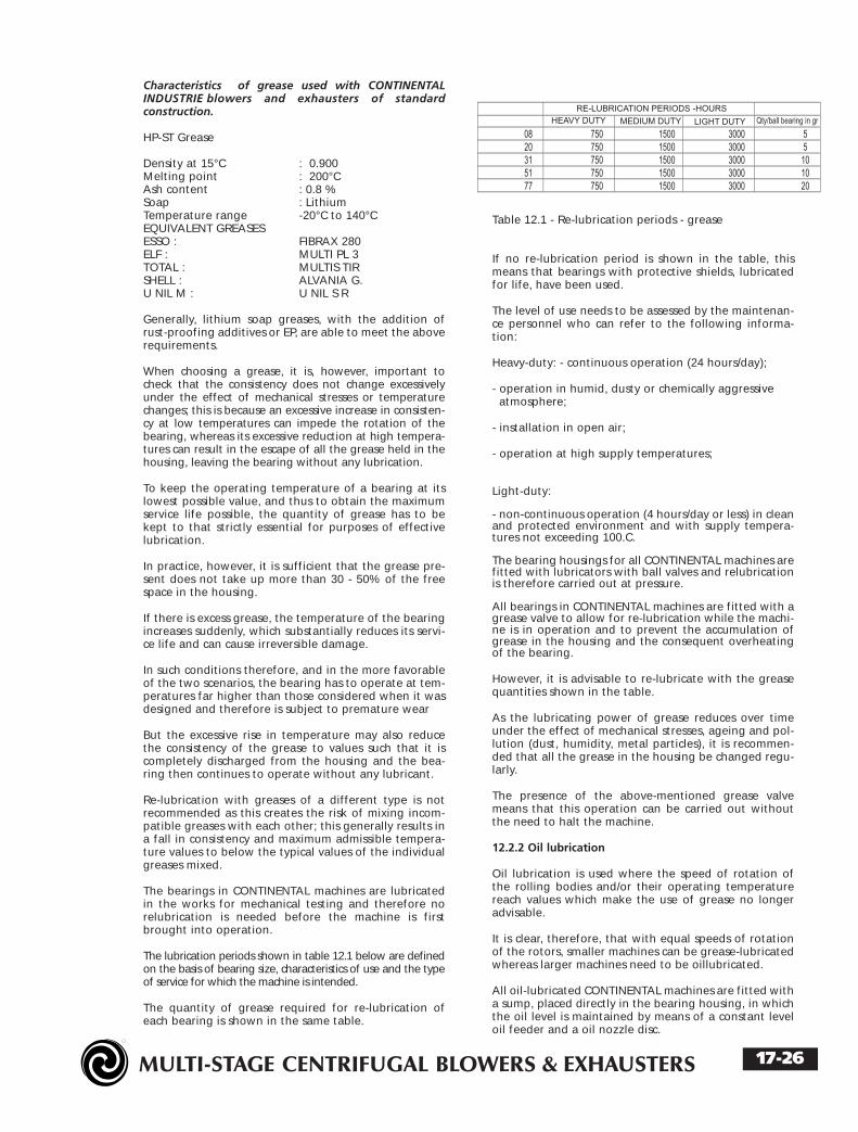
The lubrication periods shown in table 12.1 below are definedon the basis of bearing size, characteristics of use and the typeof service for which the machine is intended.
The quantity of grease required for re-lubrication ofeach bearing is shown in the same table.
Table 12.1 - Re-lubrication periods - grease
If no re-lubrication period is shown in the table, thismeans that bearings with protective shields, lubricatedfor life, have been used.
The level of use needs to be assessed by the maintenan-ce personnel who can refer to the following informa-tion:
Heavy-duty: - continuous operation (24 hours/day);
- operation in humid, dusty or chemically aggressive atmosphere;
- installation in open air;
- operation at high supply temperatures;
Light-duty:
- non-continuous operation (4 hours/day or less) in cleanand protected environment and with supply tempera-tures not exceeding 100.C.
The bearing housings for all CONTINENTAL machines arefitted with lubricators with ball valves and relubricationis therefore carried out at pressure.
All bearings in CONTINENTAL machines are fitted with agrease valve to allow for re-lubrication while the machi-ne is in operation and to prevent the accumulation ofgrease in the housing and the consequent overheatingof the bearing.
However, it is advisable to re-lubricate with the greasequantities shown in the table.
As the lubricating power of grease reduces over timeunder the effect of mechanical stresses, ageing and pol-lution (dust, humidity, metal particles), it is recommen-ded that all the grease in the housing be changed regu-larly.
The presence of the above-mentioned grease valvemeans that this operation can be carried out withoutthe need to halt the machine.
12.2.2 Oil lubrication
Oil lubrication is used where the speed of rotation ofthe rolling bodies and/or their operating temperaturereach values which make the use of grease no longeradvisable.
It is clear, therefore, that with equal speeds of rotationof the rotors, smaller machines can be grease-lubricatedwhereas larger machines need to be oillubricated.
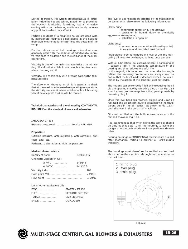
All oil-lubricated CONTINENTAL machines are fitted witha sump, placed directly in the bearing housing, in whichthe oil level is maintained by means of a constant leveloil feeder and a oil nozzle disc.
17-26
MULTI-STAGE CENTRIFUGAL BLOWERS & EXHAUSTERS
REV 092002-02US
During operation, this system produces actual oil circu-lation inside the housing which, in addition to providingthe obvious lubricating functions, has an effectivecooling action on the bearing and immediately removesany pollutants which may affect it.
Particle pollutants of a magnetic nature are dealt withby appropriate magnetic plugs placed in the housingdrains while other pollutants settle at the bottom of thesump.
For the lubrication of ball bearings, mineral oils aregenerally used with the addition of additives to impro-ve resistance to oxidation and the resistance of the lubri-cating film.
Viscosity is one of the main characteristics of a lubrica-ting oil and is that which, in our case, is a decisive factorwhen choosing an oil.
Viscosity, like consistency with greases, falls as the tem-perature rises.
Therefore when choosing an oil, it is essential to checkthat at the maximum foreseeable operating temperature,the viscosity remains at values which enable a lubricatingfilm of an adequate thickness to be formed.
Technical characteristics of the oil used by CONTINENTAL
INDUSTRIE on the standard blowers and exhausters
JAROGEAR Z.150 :
Extreme-pressure oil …………… Service API - GL5
Properties :
Extreme pressure, anti oxydating, anti corrosive, anti
foam, anti-rust.
Resistant to alteration at high temperature.
Medium characteristics :
Density at 15°C 0.892/0.917
Cinematic viscosity in Cst :
at 40°C …………… 143/148
at 100°C …………… 14.3/15.5
Viscosity index ………………………………… 103
Flash point VO………………………………… ≥ 215°C
Flow point …………………………………… ≤ -24°C
List of other equivalent oils :
ESSO :………………... SPARTAN EP 150
ELF :…………………… REDUCTELO SP 150
TOTAL: ……………… CARTER EP 150
SHELL: ……………… OMALA 150
The level of use needs to be assessed by the maintenancepersonnel with reference to the following information:
Heavy duty: - continuous operation (24 hours/day);- operation in humid, dusty or chemically
aggressive atmosphere;- installation in open air;
Light-duty: - non-continuous operation (4 hours/day or less)in a clean and protected environment.
Regardless of operating hours and level of use, the lubri-cating oil needs to be changed at least once per year.
With oil lubrication too, excess lubricant is damaging asit causes a rise in the operating temperature of thebearing and thus reduces its useful life.In this regard, it is important that when the housing isrefilled the necessary precautions are always taken toensure that the level inside it does not exceed that main-tained by the action of the constant-level oil feeder.
The housing can be correctly filled by introducing the oilvia the opening made by removing plug 1 - see Fig. 12.3- until a few drops emerge from the opening made byremoving plug 2.
Once this level has been reached, plugs 1 and 2 can bereplaced and oil can continue to be added via the trans-parent bulb in the oil feeder - as shown in Fig. 12.4 -until the level in the bulb itself stabilizes.
Oil must be filled into the bulb in accordance with themethod shown in Fig. 12.4.
It is recommended that when filling, the same oil shouldbe used as that used to fill the housing, to avoid thedanger of mixing oils which are incompatible with eachother.
Bearing housings in CONTINENTAL machines are drainedafter mechanical testing to prevent oil leaks duringtransport.
The housings must therefore be refilled as describedabove before the machine is brought into operation forthe first time.
Fig.12.3
18-26
1. filling plug2. level plug3. drain plug
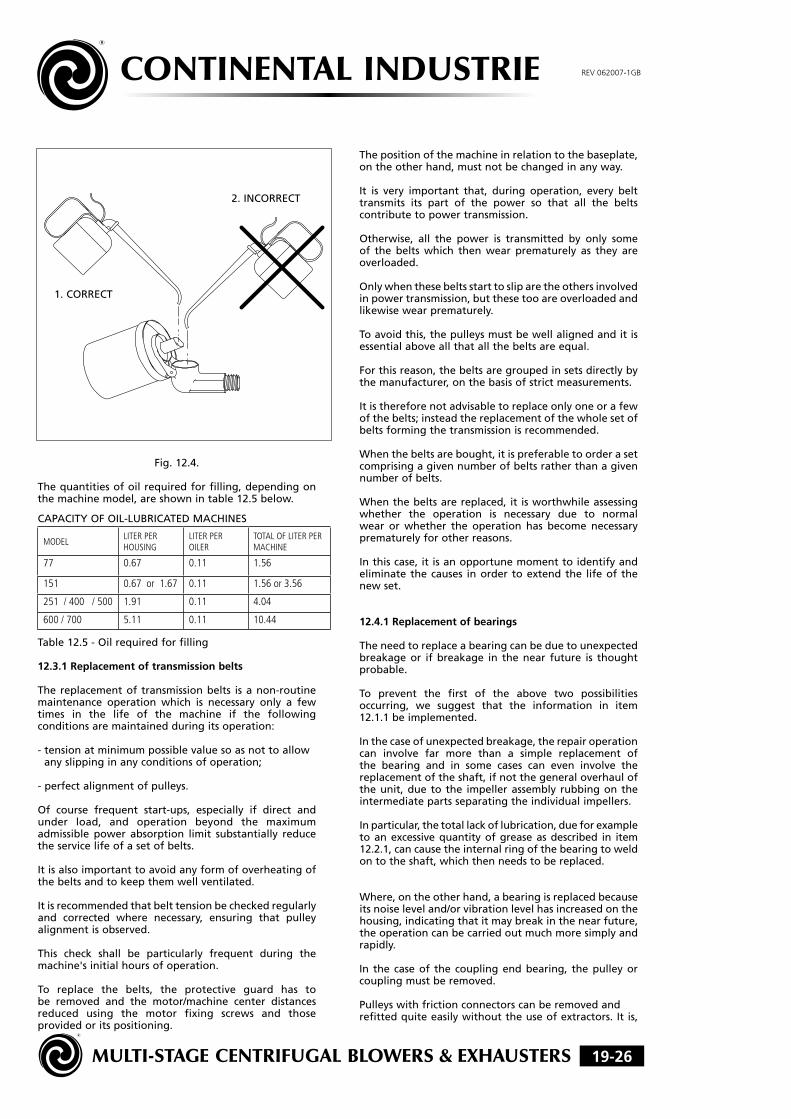
MULTI-STAGE CENTRIFUGAL BLOWERS & EXHAUSTERS 19-26
CONTINENTAL INDUSTRIE REV 062007-1GB
Fig.12.4.
Thequantitiesofoilrequiredforfilling,dependingonthemachinemodel,areshownintable12.5below.
CAPACITYOFOIL-LUBRICATEDMACHINES
MODELLITER PER HOUSING
LITER PER OILER
TOTAL OF LITER PER MACHINE
77 0.67 0.11 1.56
151 0.67 or 1.67 0.11 1.56 or 3.56
251 / 400 / 500 1.91 0.11 4.04
600 / 700 5.11 0.11 10.44
Table12.5-Oilrequiredforfilling
12.3.1Replacementoftransmissionbelts
Thereplacementof transmissionbelts isanon-routinemaintenance operation which is necessary only a fewtimes in the life of the machine if the followingconditionsaremaintainedduringitsoperation:
-tensionatminimumpossiblevaluesoasnottoallowanyslippinginanyconditionsofoperation;
-perfectalignmentofpulleys.
Of course frequent start-ups, especially if direct andunder load, and operation beyond the maximumadmissible power absorption limit substantially reducetheservicelifeofasetofbelts.
Itisalsoimportanttoavoidanyformofoverheatingofthebeltsandtokeepthemwellventilated.
Itisrecommendedthatbelttensionbecheckedregularlyand corrected where necessary, ensuring that pulleyalignmentisobserved.
This check shall be particularly frequent during themachine'sinitialhoursofoperation.
To replace the belts, the protective guard has tobe removed and the motor/machine center distancesreduced using the motor fixing screws and thoseprovidedoritspositioning.
Thepositionofthemachineinrelationtothebaseplate,ontheotherhand,mustnotbechangedinanyway.
It is very important that, during operation, every belttransmits its part of the power so that all the beltscontributetopowertransmission.
Otherwise, all the power is transmitted by only someof the belts which then wear prematurely as they areoverloaded.
Onlywhenthesebeltsstarttosliparetheothersinvolvedinpowertransmission,butthesetooareoverloadedandlikewisewearprematurely.
Toavoidthis,thepulleysmustbewellalignedanditisessentialaboveallthatallthebeltsareequal.
Forthisreason,thebeltsaregroupedinsetsdirectlybythemanufacturer,onthebasisofstrictmeasurements.
Itisthereforenotadvisabletoreplaceonlyoneorafewofthebelts;insteadthereplacementofthewholesetofbeltsformingthetransmissionisrecommended.
Whenthebeltsarebought,itispreferabletoorderasetcomprisingagivennumberofbeltsratherthanagivennumberofbelts.
Whenthebeltsarereplaced,it isworthwhileassessingwhether the operation is necessary due to normalwear or whether the operation has become necessaryprematurelyforotherreasons.
Inthiscase,itisanopportunemomenttoidentifyandeliminate thecauses inorder toextendthe lifeof thenewset.
12.4.1Replacementofbearings
Theneedtoreplaceabearingcanbeduetounexpectedbreakageor ifbreakage in thenear future is thoughtprobable.
To prevent the first of the above two possibilitiesoccurring, we suggest that the information in item12.1.1beimplemented.
Inthecaseofunexpectedbreakage,therepairoperationcan involve far more than a simple replacement ofthe bearing and in some cases can even involve thereplacementoftheshaft,ifnotthegeneraloverhauloftheunit,due to the impellerassembly rubbingon theintermediatepartsseparatingtheindividualimpellers.
Inparticular,thetotallackoflubrication,dueforexampletoanexcessivequantityofgreaseasdescribed in item12.2.1,cancausetheinternalringofthebearingtoweldontotheshaft,whichthenneedstobereplaced.
Where,ontheotherhand,abearingisreplacedbecauseitsnoiseleveland/orvibrationlevelhasincreasedonthehousing,indicatingthatitmaybreakinthenearfuture,theoperationcanbecarriedoutmuchmoresimplyandrapidly.
In the caseof the couplingendbearing, thepulleyorcouplingmustberemoved.
Pulleyswithfrictionconnectorscanberemovedandrefittedquiteeasilywithouttheuseofextractors.Itis,
1.CORRECT
2.INCORRECT

MULTI-STAGE CENTRIFUGAL BLOWERS & EXHAUSTERS
REV 092002-02US
refitted quite easily without the use of extractors. It is,however, advisable to mark their position with regard tothe shaft before removing them.
For traditional pulleys and for half couplings, on theother hand, an extractor must be used. Where possible,threaded holes are provided in the hub of the pulley orthe half coupling so that hydraulic jacks can be used.
Traditional pulleys and couplings can be heated in an oilbath for ease of refitting.
Machines with direct transmission are sometimes fitted witha coupling with a spacer which allows the coupling endbearing to be replaced without disturbing the alignment.
For oil-lubricated bearings, the housing must be drainedbefore it is removed.
With the housing cover removed, dismantle the variouscomponents (lock nut, spacers, discs etc.) until thebearing inner ring is released.
It is important to note the dismantling sequence of allthe components to be sure of refitting them in the sameposition and in the same direction.
Then remove all the screws fixing the housing to thehead and, using the two threaded holes provided on thehousing connection flange and screws of a suitable leng-th, the bearing is removed using the housing itself as anextractor.
Important :The bearing extracted in this way cannot be re-used asthe rolling bodies and tracks have been stressed.
Before continuing, all the components to be refittedmust be carefully cleaned and inspected.
This is an opportune moment to inspect and, if necessa-ry, replace the sealing rings on the shaft as they areaccessible with the housing removed.
The housing can then be refitted with all the fixingscrews thoroughly tightened.
The new bearing shall be removed from its packaging atthe latest possible moment to avoid any extraneousmatter entering it.
It is generally protected by a corrosion-proofing filmapplied directly by the works and must therefore bewashed absolutely clean in solvent (mineral or oil resinwithout acids) and then dried.
Obviously, pre-lubricated bearings with shields must notbe washed and it is sufficient to remove the protectivefilm from the internal and external rings.
Before fitting the new bearing, it is a good idea to oillightly the seats on the shaft and in the housing, toimprove their glide.
In the installation phase, pressure must never be appliedto one ring to make the other one slide, as this will cer-tainly damage the rolling bodies and the tracks.
The force necessary to overcome friction generated atthe same time at the internal and the external rings,must be applied at the same time to the two rings bymeans of a very thick ring which has an external diame-
ter slightly less than the diameter of the external ringand an internal diameter slightly greater than that ofthe internal ring.
The force via the ring can be applied using a hydrauliccylinder appropriately connected or by hitting with alead mallet.
Under no circumstances are the rings, cage or rollingbodies to be hit directly.
It is essential to check that the internal ring of the bea-ring is tightly fitted before the other components arefitted.
It is worthwhile noting that the outlet end bearing isleft axially free to absorb the thermal expansion diffe-rence between the shaft and the body of the machineand therefore its external ring can slide axially in thehousing within certain limits and does not come intocontact with the housing end cover.
The inlet end bearing, on the other hand, is connectedaxially and defines the position of the whole rotor withregard to the body of the machine.
Its internal ring is clearly tightly fitted to the shaft andthe position of the external ring is defined on the onehand by the housing support and on the other by thehousing cover. A ring with a calibrated spacer is some-times fitted between the housing cover and the bearingexternal ring.
When the inlet end bearing is replaced, it may be foundthat the shaft slides axially, returning, however, to itsoriginal position once the operation is completed.
It is possible to check that the bearing replacement ope-ration has been carried out correctly by checking thatthe rotor of the unit rotates freely manually and isrestrained axially in both directions.
Refer to items 12.2.1, 12.2.2, 12.5.1 and 12.5.2 withregard to the lubrication, pulley and coupling alignmentand belt tensioning operations which need to be carriedout before the unit is restarted.
When the unit is brought into operation, it is essentialto check that the level of vibrations on the housing andthe bearing temperature, measured on the external ringvia the appropriate hole, lie within normal values.
12.5.1 Alignment and tension of transmission belts
The alignment of the pulleys and the correct tension ofthe belts enable the useful life of the bearings and thebelts themselves to be utilized to the maximum.
Non-alignment causes asymmetric wear of the belt anddoes not allow the belts in the set to be uniformly loaded.
Generally, it is not worthwhile carrying out regularchecks on the alignment as this does not change duringoperation.
On the other hand, alignment must always be carriedout when the belts are tensioned and whenever theyare adjusted.
The external faces of the 2 pulleys must be on the samevertical plane when aligning and this is generally carriedout by placing an iron bar as shown in Fig. 12.6.
20-26

MULTI-STAGE CENTRIFUGAL BLOWERS & EXHAUSTERS
REV 092002-02US
The face of the machine pulley is taken as a referenceand the bar is placed on this, checking contact at pointsC and D.
The motor is then moved, keeping the 4 fixing screwsonly slightly slackened and adjusting screws 1, 2, 3 and 4until contact at points A and B is also made.
Any axial movements can be made by means of smallknocks with a lead or plastic mallet, if the motor size soallows, or by means of screws provided for this purpose.
Of course, the operations of pulley alignment and belttensioning affect each other.
A good practical way of streamlining these operations isas follows:
- carry out a rapid and approximate alignment with thebelts slack and tighten screws 1, 2, 3 and 4 manually;
make a preliminary and approximate tensioning of thebelts taking care, however, to turn the above-mentio-ned screws equally (for example, if screws 4 and 2 areslackened by a complete turn, turn screws 1 and 3 a com-plete revolution too);
complete alignment with the necessary precision;
complete belt tensioning to the final value, alwaystaking care to ensure that the 4 screws are rotated bythe same amount (as, in the final phase, parts of a revo-lution can be required, it is advisable to mark the head);
before fully tightening the motor anchoring screws,check the alignment once more which, given themethod followed, may require just a small final correc-tion by an axial shift of the motor.
This correction does not affect the tensioning obtained.
Fig. 12.6
Shims are only rarely needed under the motor feet tocorrect parallelism defects on the horizontal plane ofthe axes of the motor and machine.
Excessive belt tension results in an unnecessary increasein the load on the bearings and the bending moment onthe shaft.
In extreme cases, it can even cause the shaft to breakdue to fatigue.
Inadequate tension on the belts causes them to slip, ove-rheat and wear prematurely.
In extreme cases, overheating can cause irreversibledamage to the pulleys as well.
Tensioning of the trapezoidal belts which are fitted on aCONTINENTAL machine is generally carried out correctly,rapidly and easily by any expert maintenance personnel.
However, in view of the range of belts on the marketand their different characteristics, it is a good idea tohave specific data so that belt tension can be definitelyset correctly.
To determine analytically, with adequate approximation,the data required for correct tensioning, the followingdata needs to be taken from the machine served:
- D = diameter of pulley mounted on drive shaft, in mm (if possible, use the original diameter);
- d = diameter of pulley mounted on machine shaft, in mm (if possible, use the original diameter);
- I = approximate center distance between the two pulleys, in mm;
- N = motor power in kW;
- n = speed of rotation of motor in rpm;
- c = number of belts comprising the transmission;
- section of belts used.
Using table 12.7 below, the coefficients M and Y can bedetermined, depending on the belt section.
Table 12.7 - Coefficients M and Y
The following are then calculated:
V = 0.052 x n x D (velocity of belt in m/s)1, 000
f = I (deflection in mm)100
A = D - d (function of contact arc) I
With value A thus obtained, G is found from the follo-wing sequence:
where A = --> 0.00 0.10 0.20 0.30 0.40 0.50 0.60 0.70
G = --> 1.00 0.99 0.97 0.96 0.94 0.93 0.91 0.89
where A = --> 0.80 0.90 1.00 1.10 1.20 1.30 1.40 1.50G = --> 0.87 0.85 0.82 0.80 0.77 0.73 0.70 0.65
21-26

MULTI-STAGE CENTRIFUGAL BLOWERS & EXHAUSTERS
REV 092002-02US
Naturally any intermediate values need to be interpolated.
The following can now be calculated :
T = 45 x (2.5 - G) x N + M x V2 (static tension in kg)G x c x V
Fmi n = T + Y Fmax = 1.5 T + Y25 25
Fmin and Fmax are the values between which force Fmust lie, which applied to the center of the section, to asingle belt, is perpendicular to it as shown in Fig. 12.8and is able to produce a deflection equal to f mm.
Fig. 12.8
If the belts are new, Fmi n and Fmax need to be increa-sed by 30% to take account of the rapid fall in tensionoccurring during the running-in period.
Tensioning is checked after the first 4 hours of operationand corrected to the nominal Fmi n and Fmax values cal-culated above. The checks are repeated until they arefound to be stable.
12.5.2 Alignment of transmission coupling
The correct alignment of the transmission couplingallows the machine to operate at minimum vibrationlevels and enables the useful life of the bearings to beutilized to the maximum.
Before carrying out this operation, it is essential to readthe following items:
3.3.1 Direct drive using a coupling3.3.3 Pulley/belt drive with countershaft 3.3.5 Drive using a gearbox.
Alignment is carried out as follows:
* place the axes of the two shafts coupled on the samevertical plane or on two parallel vertical planes, witha specified distance between them;
* place the axes of the two shafts coupled on the samehorizontal plane or on two parallel horizontal planes,with a specified distance between them;
* keep a specified distance between the ends of the twocoupled shafts or better between the two faces of thehalf couplings.
Fig. 12.9
Radial mis-alignment and angular mis-alignment areshown in Fig. 12.9. Naturally, these can be present at thesame time.
Due to thermal expansion and other causes such as, forexample, the lubricating oil film in the plain bearings,radial thrusts by the gears etc., the position of the twoshafts coupled with the machine in normal operationcan be very different from their position when themachine is off and cold.
Therefore when aligning cold, radial mis-alignmentvalues can be prescribed calculated so as to obtain per-fect alignment when the machine is running in normaloperation.
If no specific instructions are given, the shafts must bealigned cold so as to obtain the minimum possible valueof radial and angular mis-alignment. The distance bet-ween the faces of the half couplings can be taken fromthe machine drawing.
Maximum admissible mis-alignment when hot can varydepending on the type of coupling; however, if no spe-cific instructions are given, the following tolerancesmust be used:
- distance between the half coupling faces: +/- 0.10 mm- radial mis-alignment (T.I.R.): _ 0.10 mm - angular mis-alignment: 0.50°.
The distance between the half coupling faces wherethere is a spacer can be measured by means of a caliperor an internal micrometer or otherwise by a thicknessgauge.
Radial mis-alignment can be assessed by means of a setsquare or a straight bar which is sufficiently rigid andlong, but it is preferable to use a gauge fitted as shownin Fig. 12.11 A. The T.I.R. reading (Total IndicatorReading) given by the gauge for a 180° rotation repre-sents double the actual misalignment. With reference toFig. 12.10, half of the reading for a 180° rotation from Oto 180° provides the height difference between theshaft axes. Half the reading for a 180° rotation from 90°to 270° provides the distance between the two verticalplanes on which the shaft axes are placed.
Fig. 12.10
22-26
1. RADIAL 2. ANGULARMIS-ALIGNMENT MIS-ALIGNMENT
MULTI-STAGE CENTRIFUGAL BLOWERS & EXHAUSTERS
REV 092002-02US
Angular mis-alignment can be assessed by means of acaliper, internal micrometer or a thickness gauge, but itis preferable to use a gauge fitted as shown in Fig. 12.11B. The ratio between the T.I.R. reading (Total IndicatorReading) provided by the gauge for a 180° rotation andthe diameter of the circle described by the rotation ofthe tracer point axis represents the tangent of the misa-lignment angle.
With reference to Fig. 12.10, from the reading for a 180°rotation from 0° to 180°, the angular mis-alignment isdetermined by the height of the couplings. From thereading for a 180° rotation from 90° to 270°, the angu-lar mis-alignment is determined by the transversal posi-tion of the couplings.
Machines and/or motors are moved laterally by means ofappropriate adjustment screws provided in the works. Alead mallet may be needed for smaller machineswithout adjustment screws.
Machines and/or motors are moved vertically by usingshims placed under the feet as required. When adjustingthe height of machines and/or motors with shims, thefollowing precautions are recommended:
* ensure that the feet, their bearing surfaces and everyindividual shim used are as clean as possible;
* ensure that all the anchoring screws have been tighte-ned before taking the readings;
* ensure that all the feet are completely in contact withthe shims and that the tightening of the anchoringscrews does not produce any deformation to the base-plate and/or the machine or motor.
A good practical method for alignment is as follows:
1. study the machine, the height and position of whichneeds to be considered fixed with regard to the base-plate;
2. check that its anchoring screws are centred in theholes, i.e. that it is possible to move it in all directions;
3. completely tighten the anchoring screws;
4. check that the height of the shaft is greater than orequal to the minimum required, correcting with shims ifnecessary;
5. place a gauge with a magnetic base on the base-plateand a tracer point on the machine feet close to one ofthe anchoring screws and set it to zero;
6. slacken the anchoring screws and check that thegauge does not indicate movements of more than 0.005mm (any movement greater than the given valuerequires the insertion of corrective shims);
7. repeat the operation for all the anchoring points tothe base-plate;
8. slacken the anchoring screws of the other machine;
9. measure the distance between the faces of the twohalf couplings and move the machine in an axial direc-tion until the prescribed value is reached;
10. tighten the anchoring screws;
11. while rotating the two half couplings at the same
time measure the radial mis-alignment and:
- move the machine transversally until the prescribedvalue is obtained (T.I.R. 90° - 270 ); - shim all the machi-ne feet until the prescribed value is obtained (T.I.R. 0 -180 );
12. while rotating the two half couplings at the sametime measure the angular mis-alignment and:
- move the machine transversally until the prescribedvalue is obtained (T.I.R. 90° - 270 ); - shim two of the feet of the machine until it comeswithin the prescribed tolerance (T.I.R. O - 180°)
Operations 11 and 12 affect each other reciprocally andtherefore must be repeated alternately until the correctresult is obtained.
13. repeat on this machine the operations described initems 5, 6 and 7.
23-26

MULTI-STAGE CENTRIFUGAL BLOWERS & EXHAUSTERS
REV 092002-02US
13.0.0 ANOMALIES: CAUSES AND REMEDIES
The performance of CONTINENTAL turbo blowers andturbo exhausters remains absolutely unchanged over time.The efficiency, noise level and operating temperaturesremain at their initial values indefinitely.
However, it is possible that anomalies may occur forvarious reasons of ageing.
13.1.1 Reduced performance
This can occur in the form of a reduction in the volumeand therefore in the differential pressure through themachine.
Causes and remedies:
- Inlet filter dirty. Replace filter elements.
- Valves up and down line from the machine not correctly adjusted.Check and correct.
- Pipework obstructed up and/or down line from the machine.Check and correct.
- Direction of rotation reversed following maintenance operations on the motor and electrical equipment.Check and correct
- Speed of rotation lower than nominal.This is possible only in the presence of turbines, internal combustion motors, hydraulic motors andelectric motors with a frequency variator.Check and correct
- Partial blocking (fouling) of the cavities of the impellers and/or diffusers due to the presence in the fluid processedof components which produce deposits. It may be neces-
sary to carry out a general overhaul of the machine.
In every case, original performances can always be fullyrestored.
13.2.1 Change in noise level
In no case can the sound pressure level exceed the valuesfound in the new machine.However, changes in the sound produced by the machi-ne can provide information about possible irregularoperating conditions.
- Reduction in capacity of fluid processed. Increase capacity.
13.2.1 Excessive outlet or discharge temperature
For standard machines, outlet or discharge tempera-tures above the values given in table 13.1 are consideredexcessive.The limits applicable to machines for high temperatureoperation are clearly higher and are specified separately.
13.4.1 Excessive bearing temperature
The temperature of the bearings measured on the exter-nal ring is considered excessive when it is above 110°C.
Causes and remedies:- Raised outlet/discharge temperature.
Check and correct
- Excess lubricant. Check and correct
13.5.1 Excessive power absorption
Power absorption is always directly proportional to themass capacity of the fluid processed; therefore any powerabsorption increase indicates an increase in capacity.An increase in pressure drop, at inlet or outlet, trans-lates, on the other hand, in a reduction in capacity andthus in reduced power absorption.
Causes and remedies:- Valves up and/or down line from the machine not correctlyadjusted.Check and correct
- Change in inlet conditions. Reduce capacity.
- Valves up line and down line from machine completelyopen (starting problem).Check and correct
- Presence of liquid inside the machine (starting problem).Open the drainage plugs on all diffusers and theoutlet or discharge head.
13.6.1 High vibration level
Vertical, horizontal and axial vibration values measuredon the bearing housings can be assessed by using thegraph shown in Fig. 13.2.
Fig. 13.2
24-26

MULTI-STAGE CENTRIFUGAL BLOWERS & EXHAUSTERS
REV 092002-02US
The areas in the graph are defined by the curves of thethree effective reference velocities (R.M.S.). Naturally,the amplitude values vary depending on the speed ofrotation of the machine.
Causes and remedies:
Deterioration in ball bearings. Replace bearings.
Mis-alignment following maintenance operations.Check and correct alignment.
Imperfect contact between the feet of the machineand/or the motor and/or the base-plate followingmaintenance operations.
Check and correct the contact of the feet of the machi-ne and/or motor with the base-plate.
Imperfect contact between the base-plate and its sup-ports on the foundation following maintenance opera-tions.
Check and correct the contact of the base-plate withsupporting shock-absorbing blocks.
Belt defective following maintenance operations.Identify the defective belt using a stroboscopic
Rotor imbalance due to excessive tension of belts follo-wing maintenance operations.Check and correct
Rotor imbalance due to deposits on the impellers (fouling).A general machine overhaul may be necessary.
Rotor imbalance due to corrosion of impellers. General overhaul required.
Rotor imbalance due to breakage of impellers. General overhaul required.
Transmission via the foundations following the startupof machinery in adjacent zones.Check and improve isolation.
Causes and origins can always be identified by vibrationanalysis, using appropriate equipment.
14.0.0 SPARE PARTS
Thanks to the extreme simplicity of their design,CONTINENTAL turbo blowers and turbo exhausters canoperate for extremely long periods before spare partsare needed. However, it is a good idea to keep a stockof the recommended set of spare parts for keeping themachine in operation.
14.1.1 Recommended set
The following list is with reference to standardmachines.
Spare parts for any particular components and/or
fittings must be provided in addition:
- bearing end cover gasket- bearing lock nut- bearing lock washer- bearing- bearing housing gasket (if present)- carbon ring housing gasket(if present)- carbon ring (if present)- oil feeder (if present)- set of transmission belts (if present).
14.2.1 Consumables
These are restricted to:
- filter cartridges (if present)- lubricant.
14.3.1 Ordering
The reference number of the spare parts can be foundon the section drawing of the machine and the attachedcomponents list.
When ordering, it is advisable to give the serial numberof the machine, found on the plate fixed to the machi-ne itself, or any other reference to help identify it.
All spare parts can be ordered from:
CONTINENTAL BLOWER, LLC23 Corporate Circle
East Syracuse, NY 13057
TEL.: 315-451-5410FAX: 315-451-5950
However, repairs and/or overhauls of CONTINENTALturbo blowers and turbo exhausters can also be carriedout by a maintenance service or workshop specializingin rotating machines found throughout the country,provided that they have sufficiently expert personneland the necessary tooling.
25-26

MULTI-STAGE CENTRIFUGAL BLOWERS & EXHAUSTERS
REV 092002-02US
15.0.0. ASSISTANCE
Requests for technical assistance should be adressed to :
CONTINENTAL BLOWER, LLC23 Corporate Circle
East Syracuse, NY 13057
TEL.: 315-451-5410 FAX: 315-451-5950
15.1.1 On-site repairs
All running repairs, i.e those not requiring thereplacement of impellers, the shaft or stator parts(heads and/or diffusers), can be conveniently carried outon site by maintenance service personnel or externalworkshop personnel.
Naturally, it is also possible to request the on-siteservices of specialized CONTINENTAL personnel able toreact within 48 hours of a request.
Services are provided on the basis of tariffs current onthe date of the intervention and shall be requested bymeans of a regular written order.
15.2.1 Repairs in our workshops
If the repair requires the replacement of impellers, theshaft or stator parts (heads and/or diffusers), the machi-ne needs to be completely stripped and the dynamicrebalancing of the rotor needs to be carried out.
Where the maintenance service or the external work-shops available are not able to carry out the operation,it may be appropriate to send the machine to our work-shop for an overhaul; this will be carried out on the basisof acceptance by the client of an estimate given for thiswork.
When under repair, the machine is completely dismant-led, all the parts are cleaned, checked and replacedwhere necessary, the rotor is rebalanced dynamicallyand the repaired machine undergoes mechanical testsand is repainted.
Overhauled machines are covered by guarantee for 12 months.
26-26


![]T IO C:; B(m+B|B](https://static.fdocuments.us/doc/165x107/5ae7e3fc7f8b9a8b2b8f3aa2/t-io-c-bmbb-mb-star-gkdm-s-qo-d-o-a-t-cn-b-h6-gc-l-qc-dm-.jpg)


