IO Ninja Hardware Manual (NHM)
23
Copyright Tibbo Technology 2000-2019 IO Ninja Hardware Manual
Transcript of IO Ninja Hardware Manual (NHM)

Copyright Tibbo Technology 2000-2019
IO Ninja Hardware Manual

IO Ninja Hardware Manual (NHM)I
©2000-2019 Tibbo Technology Inc.
Table of ContentsIntroduction 1
Serial Tap 1
................................................................................................................................... 4Block Diagram
................................................................................................................................... 4Using the Serial Tap
................................................................................................................................... 5Wedge RS232 monitoring
................................................................................................................................... 7Specifications
I2C/SPI Tap 8
................................................................................................................................... 9Using I2C/SPI Tap
............................................................................................................................................................... 11I2C Mode Screenshot
............................................................................................................................................................... 12SPI Mode Screenshots
................................................................................................................................... 14Using Build-in Test Generator
................................................................................................................................... 16Specifications
Ethernet Tap 17
................................................................................................................................... 19Using Ethernet Tap
............................................................................................................................................................... 20Ethernet Tap Plugin Screenshot
................................................................................................................................... 20Specifications
Update history 21

1Introduction
©2000-2019 Tibbo Technology Inc.
Introduction
Last update: 09DEC2019
Manual Update History
This Manual covers IO Ninja-compatible hardware:
· Serial Tap
· I2C/SPI Tap
· Ethernet Tap
Other types of hardware sniffers will be available in the near future.
Serial Tap
Serial Tap is an affordable serial sniffer that can monitor RS232, RS485, and TTL-level UART communications. The Tap connects to your PC via a USB cable and iscompatible with IO Ninja terminal/sniffer software.
Features

2 IO Ninja Hardware Manual (NHM)
©2000-2019 Tibbo Technology Inc.
· The Serial Tap is designed for use with IO Ninja software (http://ioninja.com/).
· Monitors TX, RX, RTS, CTS, DTR, and DSR lines [Note 1] of serial ports.
· All inputs are connected to an 18-position, quick-release terminal block.
· Has three operating modes: RS232, RS485 [Note 2], and UART (TTL [Note 3]),selectable via a slide switch:
oRS232 mode:
§ Two onboard DB9 connectors — male and female — offer true "cable wedge"
sniffing [Note 4];
§ Six jumpers for swapping and loopbacking signals within RX/TX, RTS/CTS, and
DTR/DSR pairs [Note 5];
§ Six bi-color LEDs indicate the status of monitored lines and allow distinguishingbetween the positive voltage (red), negative voltage (green), and zero
voltage (off) states [Note 5];
§ DB9 connectors additionally pass through DCD and RI signals (withoutmonitoring them).
oRS485 mode allows to monitor TX and RX signal pairs.
oUART (TTL) mode allows to monitor UARTs of IC chips with logic levels from 3.3Vto 5V.
· Full-speed (12Mbps) USB2.0 interface on a USB-C connector.
· Six yellow LEDs indicate the state of six monitored lines as they enter the USB
controller. LEDs turn on when the lines go LOW [Note 6].
· USB-powered, no additional external power necessary.
· Supplied with a USB-C cable and two DB9 gender changers.
· Compact, outside dimensions only 82 x 74 x 30 mm.
Note 1
A more accurate version of this statement would be: "Monitors two TX, two RTS,and two DTR lines," but that would be somewhat confusing to the reader. Forclarity, we chose to list the lines as they are commonly known: TX, RX, RTS, CTS,DTR, and DSR. Keep in mind, however, that when it comes to sniffers, these namesare relative and depend on the view. For two interconnected serial devices, a TXline on one end is an RX line on the other end. If so, which line is a "TX" and whichline is an "RX" from the sniffer's point of view? Only you can answer this question.The Serial Tap itself has two inputs capable of monitoring serial data lines. Althoughthey are both identical inputs, one is marked "TX" and another one is marked "RX."
The same goes for other signals — RTS, CTS, DTR, and DSR. All these lines areinputs of the Tap. We gave them "regular" names to make the use of the Serial Tapintuitively easier. The same goes for RS485 lines. RX+/- and TX+/- pairs are bothinputs of the Serial Tap.
This said, the Serial Tap incorporates two DB9 connectors, for which the distinctionbetween TX and RX lines, RTS and CTS lines, and DTR and DSR lines is real. To giveour terminology an anchored point of view, we have decided that the DB9-Mconnector on the left of the Tap is our "primary side" RS232 connector. For theentire board, all signal names are consistent with the standard pin assignment ofthis primary DB9-M connector. Of course, all "anchoring" disappears as soon as youabandon DB9s and plug into the terminal block lines.
Note 2

3Serial Tap
©2000-2019 Tibbo Technology Inc.
These inputs can also be used for monitoring RS422 communications.
Note 3
"TTL" here means "digital signals of microcontrollers, microprocessors, and otherICs." TTL inputs of the Serial Tap are also compatible with CMOS circuitry. Mostimportantly, "TTL" serial signals are usually inverted with respect to RS232 signals: aLOW (negative voltage) on an RS232 line corresponds to a HIGH level on a serialTTL (CMOS) line, and HIGH (positive voltage) on an RS232 line corresponds to aLOW level on a serial TTL (CMOS) line.
Note 4
TX, RX, RTS, CTS, DTR, and DSR lines of the primary DB9 connector located on theleft of the Serial Tap are connected in parallel with RS232 inputs on the terminalblock. This can be seen on the Block Diagram of the Serial Tap.
Note 5
Jumpers and bi-color LEDs on RS232 lines give the Serial Tap the second use as asimple mating and signal checking tool for serial devices.
Note 6
This statement pertains to the latest revision D of the product. On the earlier (andnow obsolete) revision C, yellow LEDs used to turn on when the lines went HIGH.

4 IO Ninja Hardware Manual (NHM)
©2000-2019 Tibbo Technology Inc.
Block Diagram
Using the Serial TapTo start using the Serial Tap:
· Install and run IO Ninja software (http://ioninja.com/).
· On the Serial Tap, slide the mode selection switch into the desired positiondepending on what interface you will be using — RS485, RS232, or UART (TTL).
· Connect into the corresponding group of terminals on the terminal block. When inthe RS232 mode, you can also employ wedge RS232 monitoring method.
· Plug the Serial Tap into the USB port of your PC.
· Launch the Serial Tap plugin.
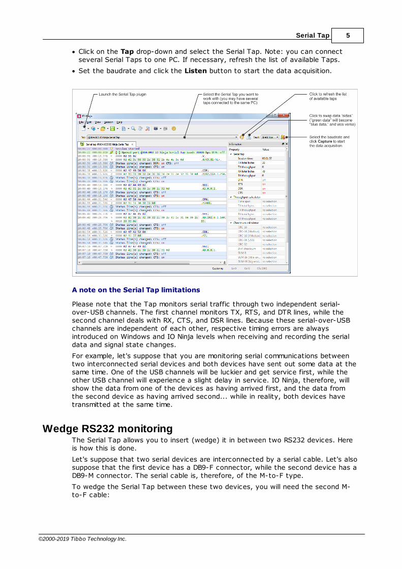
5Serial Tap
©2000-2019 Tibbo Technology Inc.
· Click on the Tap drop-down and select the Serial Tap. Note: you can connectseveral Serial Taps to one PC. If necessary, refresh the list of available Taps.
· Set the baudrate and click the Listen button to start the data acquisition.
A note on the Serial Tap limitations
Please note that the Tap monitors serial traffic through two independent serial-over-USB channels. The first channel monitors TX, RTS, and DTR lines, while thesecond channel deals with RX, CTS, and DSR lines. Because these serial-over-USBchannels are independent of each other, respective timing errors are alwaysintroduced on Windows and IO Ninja levels when receiving and recording the serialdata and signal state changes.
For example, let's suppose that you are monitoring serial communications betweentwo interconnected serial devices and both devices have sent out some data at thesame time. One of the USB channels will be luckier and get service first, while theother USB channel will experience a slight delay in service. IO Ninja, therefore, willshow the data from one of the devices as having arrived first, and the data fromthe second device as having arrived second... while in reality, both devices havetransmitted at the same time.
Wedge RS232 monitoringThe Serial Tap allows you to insert (wedge) it in between two RS232 devices. Hereis how this is done.
Let's suppose that two serial devices are interconnected by a serial cable. Let's alsosuppose that the first device has a DB9-F connector, while the second device has aDB9-M connector. The serial cable is, therefore, of the M-to-F type.
To wedge the Serial Tap between these two devices, you will need the second M-to-F cable:

6 IO Ninja Hardware Manual (NHM)
©2000-2019 Tibbo Technology Inc.
Of course, DB9 genders on the serial devices may differ from the above example,and so your serial arrangement may be different. To aid you in the "wedgingprocess," each Serial Tap comes with two DB9 gender changers.
Jumper pairs
The Serial Tap has an additional useful feature allowing you to swap and loopbackthe signals in TX/RX, RTS/CTS, and DTR/DSR signal pairs. To achieve this, twojumpers are provided for each of the three pairs. There are three standard jumperconfigurations:
· Normal — In this position, the lines are arranged in such a way that wedging theTap between the serial devices does not change anything. Meaning, TX on oneend goes to RX on another end, and vice versa.
· Swapped — This swaps signals in a pair. Meaning, TX goes to TX, and RX goesto RX.
· Loopbacked — Both serial devices "receive back" their own signals. Meaning, theTX line on each side "comes back" through the RX line.
The following diagram illustrates the jumper arrangements. The diagram shows thejumpers for the TX and RX signal pair. RTS/CTS and DTR/DSR jumpers work in thesame way.

7Serial Tap
©2000-2019 Tibbo Technology Inc.
SpecificationsThe Serial Tap is supplied with a USB cable and two DB9 gender changers.
Hardware specifications
USB port USB 2.0, full-speed (12MHz), USB-C connector
Maximum baudrate 2,764,800 bps
Operating temperature 0 to +60 degrees C
Operating relative humidity 10-90%
Mechanical dimensions 82 x 74 x 30 mm
All specifications are subject to change without notice and are for reference only.Tibbo assumes no responsibility for any errors in this Manual and does not makeany commitment to update the information contained herein.
Is the data you are looking for missing from the above table? Do not just assumethat you know the answer — talk to Tibbo! Remember, that the ultimateresponsibility for all decisions you make regarding the use and the mode of use ofTibbo products lies with you, our Customer.

8 IO Ninja Hardware Manual (NHM)
©2000-2019 Tibbo Technology Inc.
I2C/SPI Tap
I2C/SPI Tap is an affordable sniffer that can monitor I2C and SPI communications.The Tap connects to your PC via a USB cable and is compatible with IO Ninjaterminal/sniffer software.
Features
· Designed for use with IO Ninja software (http://ioninja.com/).
· Reliably captures I2C traffic at clock speeds of up to 700KHz and SPI traffic at
clock speeds of up to 24MHz [Note 1]; all four SPI modes are supported.
· Incorporates an I2C and SPI test sequence generator for self-testing the Tap.
· Based on Intel MAX10 FPGA.
· Has 16 buffered IO lines D0~15 connected to a quick-release terminal block.
· All buffers act as level shifters allowing the Tap to work with logical signals in the1.8V-5V range.
· Eight LEDs onboard:
oGreen Ready LED;

9I2C/SPI Tap
©2000-2019 Tibbo Technology Inc.
oTwo general-purpose green LEDs M0 and M1 for mode indication;
oFour yellow LEDs for indicating the state of IO lines D0~3 (sufficient for
monitoring I2C and SPI communications);
oBlue Power LED.
· Built-in test generator outputs fixed I2C and SPI data sequences.
· High-speed (480Mbps) USB2.0 interface on a USB-C connector.
· Supplied with a USB-C cable.
· USB-powered, no additional external power necessary.
· Compact, outside dimensions only 82 x 74 x 30 mm.
· Product functionality may be expanded in the future:
oOnboard FPGA is reconfigurable via the USB interface;
oSixteen IO lines provide ample room to grow;
oIt is envisioned that the product's abilities may be expanded to handle such
protocols as...
§ Quad-SPI;
§ SDIO;
§ Single-wire bus;
§ and more!
Note 1
This number depends on the host PC's performance and its "workload." Captureddata may be lost if a PC's USB channel is unable to receive it in a timely manner.Our tests have shown that an average i7-based desktop PC (that is not performingother time-critical tasks) easily captures sustained SPI traffic with clock speeds upto 24MHz.
Using I2C/SPI Tap
Connecting I2C and SPI signals to the Tap
To monitor I2C traffic, connect your I2C bus to terminals D0 (SCL) and D1 (SDA)terminals.
To monitor SPI traffic, connect your SPI bus to terminals D0 (SCLK), D1 (MOSI), D2(MISO), and D3 (SS).
Note that the Tap has a built-in generator of test signals.
Selecting the logic voltage levels
I2C/SPI Tap can work with logic voltage levels from 1.8V to 5V. For correctoperation of the Tap, you must select correct reference voltage for the Tap's levelshifters.
This is done using the IO VOLTAGE SELECT jumper. Two reference voltages — 3.3Vand 5V — are provided by the Tap itself. Other logic levels require an externalreference voltage applied to the VIO terminal. To select the VIO input, put thejumper into the VIO position and connect the VIO terminal to the external voltagesource (typically, the VCC line of the device you are monitoring). For example, if you

10 IO Ninja Hardware Manual (NHM)
©2000-2019 Tibbo Technology Inc.
are tapping into the I2C bus of a 1.8V device, then connect the VIO terminal to the1.8V power used by this device.
No SDA pull-up resistor on the Tap
The SDA line of I2C interface requires a pull-up resistor. This Tap does not containsuch a resistor and expects that the monitored device will have it.
Setting up IO Ninja
· Install and run IO Ninja (http://ioninja.com/).
· Plug the Serial Tap into the USB port of your PC.
· Launch the I2C/SPI Tap plugin.
· Click on the Tap drop-down and select the target I2C/SPI Tap. Note: you canconnect several I2C/SPI Taps to one PC. If necessary, refresh the list of availableTaps.
· Select the I2C or SPI protocol in the Protocol dropdown.
· In the case of SPI protocol, set the SPI mode, word length (SPI data bits), andendianness in the Settings dialog.
· Click the Capture button to start the data acquisition. At this moment, IO Ninjawill check the Tap's configuration. If the Tap is configured for a different protocol(for example, for SPI while you need I2C), IO Ninja will reconfigure the Tap. Thiswill only take a couple of seconds. Note that the Tap has two green LEDs M0 andM1. These LEDs indicate the Tap's configuration:
oIn the I2C mode, M0 is ON, and M1 is OFF;
oIn the SPI mode, M0 is OFF, and M1 is ON.
· When monitoring SPI traffic, you can also flip (swap) MISO and MOSI lines' data.From the Tap's point of view, MOSI and MISO are abstract labels. This is becausethe Tap is neither SPI slave nor SPI master. The tap is a passive observer, and soit is up to you to decide which of the two SPI data lines is MISO, and which isMOSI. Rather than physically swapping the wires connected to the Tap's terminalblock, you can achieve the same result by clicking Flip SPI MISO/MOSI.
The above is illustrated by screenshots in I2C Mode Screenshot and SPI ModeScreenshots. The screenshot depicting IO Ninja in I2C mode also contains importantcomments on Ninja's representation of I2C traffic, specifically, how unacknowledged(unACKed) bytes are shown.

11I2C/SPI Tap
©2000-2019 Tibbo Technology Inc.
I2C Mode Screenshot

12 IO Ninja Hardware Manual (NHM)
©2000-2019 Tibbo Technology Inc.
SPI Mode ScreenshotsThere are two screenshots in this section.

13I2C/SPI Tap
©2000-2019 Tibbo Technology Inc.

14 IO Ninja Hardware Manual (NHM)
©2000-2019 Tibbo Technology Inc.
Using Build-in Test Generator
I2C and SPI firmware (FPGA configurations) for this Tap include test generatorsproducing sustained test traffic at 400KHz and 24MHz respectively.
Test I2C signals are generated on D14 (SDA) and D15 (SCL).
Test SPI signals are generated on D12 (SS), D13 (MISO), D14 (MOSI), and S15(SCLK).
To receive the test traffic, connect two or four wires as shown on the diagramabove.
Here is the data you will receive from the test generators.
I2C Test Sequence

15I2C/SPI Tap
©2000-2019 Tibbo Technology Inc.
SPI Test Sequence

16 IO Ninja Hardware Manual (NHM)
©2000-2019 Tibbo Technology Inc.
SpecificationsI2C/SPI Tap is supplied with a USB cable.
Hardware specifications
USB port USB 2.0, high-speed (480MHz), USB-Cconnector
Supported I2C clock speeds Up to 700KHz
Supported SPI clock speeds Up to 24MHz [Note 1]
Operating temperature 0 to +60 degrees C
Operating relative humidity 10-90%
Mechanical dimensions 82 x 74 x 30 mm

17I2C/SPI Tap
©2000-2019 Tibbo Technology Inc.
Note 1
This number depends on the host PC's performance and its "workload." Captureddata may be lost if PC's USB channel is unable to receive it in a timely manner. Ourtests have shown that an average i7-based desktop PC (that is not performingother time-critical tasks) easily captures sustained SPI traffic with clock speeds upto 24MHz.
All specifications are subject to change without notice and are for reference only.Tibbo assumes no responsibility for any errors in this Manual and does not makeany commitment to update the information contained herein.
Is the data you are looking for missing from the above table? Do not just assumethat you know the answer — talk to Tibbo! Remember, that the ultimateresponsibility for all decisions you make regarding the use and the mode of use ofTibbo products lies with you, our Customer.
Ethernet Tap
Ethernet Tap is an affordable sniffer for monitoring Ethernet traffic flowing through asingle Ethernet connection. To monitor Ethernet traffic, an Ethernet cable that wasinitially connecting a switch (hub) to an Ethernet device is replaced by two Ethernetcables and the Ethernet Tap is inserted between them, in what is known as a

18 IO Ninja Hardware Manual (NHM)
©2000-2019 Tibbo Technology Inc.
"wedge" fashion. The Tap passes the Ethernet traffic through with a delay equal toabout 5.2uS.
The Tap connects to your PC via a USB cable and is compatible with IO Ninjaterminal/sniffer software.
Features
· Designed for use with IO Ninja software (http://ioninja.com/).
· Reliably captures 10Base-T and 100Base-T Ethernet traffic [Note 1][Note 2].
· Based on Intel MAX10 FPGA.
· Six LEDs onboard:
oGreen Ready LED;
oGreen 100Mbps and yellow Link/Activity LEDs for the left RJ45 jack;
oGreen 100Mbps and yellow Link/Activity LEDs for the right RJ45 jack;
oBlue Power LED.
· High-speed (480Mbps) USB2.0 interface on a USB-C connector.
· Supplied with a USB-C cable.
· USB-powered, no additional external power necessary.
· Compact, outside dimensions only 82 x 74 x 30 mm.
· The product is field-upgradeable via the USB interface.
Note 1
As long as your PC is fast enough to receive all the captured data. Some data maybe lost if a PC's USB channel is unable to receive it on time. Our tests have shownthat an average i7-based desktop PC (that is not performing other time-criticaltasks) easily captures 100BaseT traffic even under high Ethernet load conditions.
Note 2
The Tap does not allow mixing 10BaseT and 100BaseT connections. Both sides ofthe Tap must have the same connection speed. That means that you may notconnect one side of the Tap to a 100Base-T device, and another side—to a10Base-T device.

19Ethernet Tap
©2000-2019 Tibbo Technology Inc.
Using Ethernet Tap
Connecting Ethernet Tap
Setting up IO Ninja
· Install and run IO Ninja (http://ioninja.com/).
· Plug the Ethernet Tap into the USB port of your PC—the blue Power LED shallturn on. If the Tap is loaded with a valid configuration file, the green Ready LEDwill also turn on.
· Launch the Ethernet Tap plugin (we have a screenshot here).
· Click on the Tap drop-down and select the target Ethernet Tap (you can connectseveral Ethernet Taps to one PC, so selecting the right one may be necessary).You can refresh the list of available Ethernet Taps by clicking the Refresh buttonto the right of the Tap drop-down.
· Click the Capture button to start the data acquisition. At this moment, IO Ninjawill check the Tap's internal firmware. If the Tap firmware is outdated, IO Ninja willupload the new firmware into the Tap. This will only take a couple of seconds.
Filtering captured data
Most networks experience constant and varied traffic, while your attention is usuallyfocused on something particular. Filtering allows you to only display the packetsthat satisfy the defined criteria. The filter is set by entering a filter string into a Filter textbox and pressing the Apply button to the right of the field. When settinga filter, follow the "pcap filter" format, and if you don't know what that is, Google"pcap-filter."
Clicking the Apply button verifies the filter string correctness and enables that filterif no problems are found. If the filter string is invalid, the Filter textbox will turn red.

20 IO Ninja Hardware Manual (NHM)
©2000-2019 Tibbo Technology Inc.
Note that the Ethernet Tap captures all data flowing through it, and the filtering isperformed on the already recorded data. Changing the filter affects what packetsare displayed on the screen and is retroactive, meaning that setting a new filtercauses IO Ninja to re-output the entire log with the new filter setting applied.
Ethernet Tap Plugin Screenshot
SpecificationsEthernet Tap is supplied with a USB cable.
Hardware specifications
USB port USB 2.0, high-speed (480MHz), USB-Cconnector
Throughput Up to 100BaseT Ethernet's real-life throughput [Note 1] [Note 2]
Operating temperature 0 to +60 degrees C
Operating relative humidity 10-90%
Mechanical dimensions 82 x 74 x 30 mm

21Ethernet Tap
©2000-2019 Tibbo Technology Inc.
Note 1
As long as your PC is fast enough to receive all the captured data. Some data maybe lost if a PC's USB channel is unable to receive it on time. Our tests have shownthat an average i7-based desktop PC (that is not performing other time-criticaltasks) easily captures 100BaseT traffic even under high Ethernet load conditions.
Note 2
The Tap does not allow mixing 10BaseT and 100BaseT cables. Both sides of the Tapmust have the same connection speed. That means that you may not connect oneside of the Tap to a 100Base-T device, and another side—to a 10Base-T device.
All specifications are subject to change without notice and are for reference only.Tibbo assumes no responsibility for any errors in this Manual and does not makeany commitment to update the information contained herein.
Is the data you are looking for missing from the above table? Do not just assumethat you know the answer — talk to Tibbo! Remember, that the ultimateresponsibility for all decisions you make regarding the use and the mode of use ofTibbo products lies with you, our Customer.
Update history09DEC2019
· Documented the Ethernet Tap.
09SEP2019
· Corrected an error in the Serial Tap documentation (UART (TTL) mode allows tomonitor UARTs of IC chips with logic levels from 3.3V, not 1.8V as was previouslystated).
26MAR2019
· Documented the I2C/SPI Tap.
18SEP2018
· Updated Serial Tap documentation to reflect the changes made in revision D.
03JUL2018
· Documented the Serial Tap.