Investigation of Distortion-Induced Fatigue Cracking in a Seismically-Retrofitted Bridge Riyadh...
33
Investigation of Distortion- Induced Fatigue Cracking in a Seismically-Retrofitted Bridge Riyadh Hindi, PhD, PEng Will Lindquist, PhD, PE Ahmed Ibrahim, PhD, PE Ying Tung, PhD Candidate
-
Upload
johanne-waddoups -
Category
Documents
-
view
215 -
download
1
Transcript of Investigation of Distortion-Induced Fatigue Cracking in a Seismically-Retrofitted Bridge Riyadh...

Investigation of Distortion-Induced Fatigue Cracking in a Seismically-Retrofitted Bridge
Riyadh Hindi, PhD, PEng Will Lindquist, PhD, PE
Ahmed Ibrahim, PhD, PEYing Tung, PhD Candidate

Presentation Outline
• Brief Introduction and Background• Linear Elastic Finite Element Analysis
• Moving Live Loads• Stationary Live Loads• Temperature Loads
• Preliminary Fatigue Calculations• Potential Repair Options• Field Monitoring• Summary and Conclusions

Project Location
Section 1
Section 2
Section 3Section 4
Section 3:• AADT approximately 94k, 14k trucks
• Composite reinforced CIP deck
• Cracks found on interior girders in the web- gap region near new diaphragms

Retrofit Plan & Cross-Section Views

Retrofit Plan & Cross-Section Views

Retrofit Plan & Cross-Section Views
Crack Locations
*Cracks are located on interior girders

Finite Element Analysis
• Loads / Load Application• Dead Load• Live Load• Temperature Load
• Finite Element Models (FEMs) evaluated to date• SAP2000• Abaqus
• Future Work

Concrete Deck
Longitudinal Steel Girders
Rigid Links
Shared nodes in Stiffener-Web intersection
Web-gap region
Top flange
Connection plate (stiffener)

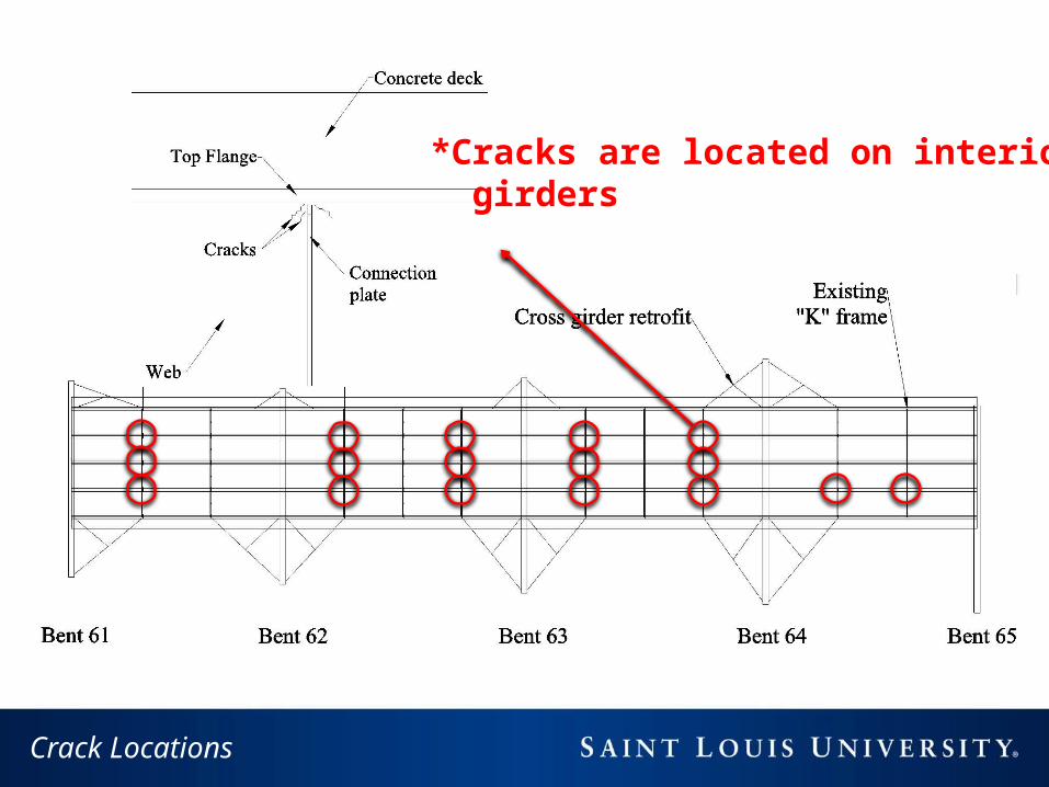
Loading
• Dead Load: Total weight of the structure
• Temperature Load : ± 80˚F applied to the entire model
• Moving Load / Point Truck Load : Exterior girder Interior girder
Load Applied
Point Loads / Moving Loads
4k4k
16k16k
16k16k
Bent 64
320 lb/fton both
* Wheels are 6 ft. apart

Point Loads / Moving Loads
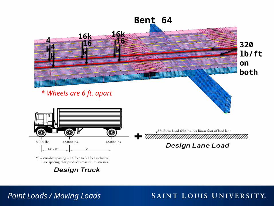
FEMs Developed with SAP2000
Loads• Temperature Loads• Moving Loads + Lane Load• Point Load + Lane Load
Models• Original• Retrofit• Retrofit Options
G5G4G3G2G1
SAP2000 Model List
Original Model Retrofit (Fixed braces)
Retrofit (Braces free to
rotate)
Retrofit (Weld web gap at
crack location)
Retrofit(Remove retrofit
links at B64)
Dead load Moving Load (G1) Moving Load (G2) Moving Load (G4) Moving Load (G5)
Temperature Load (±80˚F) Point Truck + Lane Load (G1) Point Truck + Lane Load (G2) Point Truck + Lane Load (G4) Point Truck + Lane Load (G5)

SAP2000 Model
Bent 61
Bent 62
Bent 63
Bent 64
Retrofit Cross-Bracing left of Bent 64
Bent 64 -• Crack Locations near B64 have slightly higher stresses• Fine mesh and shell elements for the bracing at B64.

Temperature Load = 80° F | B64
Average Principal Tensile Stress
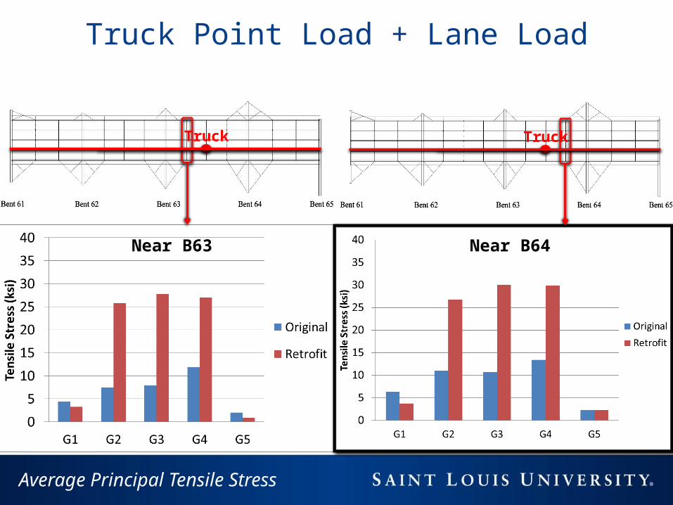
Average Principal Tensile Stress
Truck Truck
Near B63 Near B64
Truck Point Load + Lane Load
Truck

Truck Point Load vs. Moving Load | B64
Moving load on G2 Truck + Lane load on G2
Truck
Average Principal Tensile Stress

Interior vs. Exterior Girders | B64
Average Principal Tensile Stress
Truck + Lane load on G1 Truck + Lane load on G2
TruckTruck
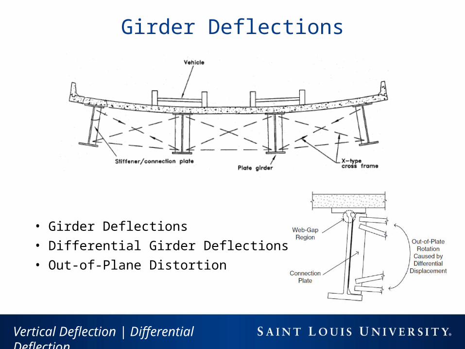
Vertical Deflection | Differential Deflection
• Girder Deflections• Differential Girder Deflections• Out-of-Plane Distortion
Girder Deflections

Vertical Deflection | Truck Load

Vertical Differential Deflection
Differential Girder Deformation

Out-of-Plane Displacement
Y-axis
“X-Bracing” “K-Bracing” “X-Bracing”

Preliminary Fatigue Analysis
Assumptions
• ADTT = 14,000; ADTTSL = 14,000×0.85=11,900
• AASHTO HS-15 Fatigue Truck (54 kips)• Category C to C’ detail; CAFT = 10 to 12 ksi• 2 lanes available to trucks• Stress Range = 14.2 ksi

1.0E+05 1.0E+06 1.0E+071
10
100
Category B Category C' Stiffeners Category C Other Attachments
Category D Cycle Limit with σ=14.2 ksi
N-Number of Cylces
Stre
ss R
ange
in k
si
AASHTO S-N Curve
14.2
1,537,000

Potential Repair Options
• Continue Monitoring / Drill Crack Arrestor Holes• Stiffen the Stiffener Plates• Remove retrofit links / diaphragms • Loosen diaphragm bolts / Install under-sized bolts• Soften the Stiffener Plates• Field Monitoring

Crack Arrestor Holes
AASHTO Fatigue Truck
Δσ = 5.7 ksi
Δσ = 13.0 ksi
Δσ = 25.2 ksi

AASHTO Fatigue Truck
27Positive Connection / Remove Links
Δσavg = 14.2 ksi
Δσavg = 0.7 ksi
Δσavg = 13.8 ksi

AASHTO Fatigue Truck
28Modify Connections / Loosen Bolts
Δσavg = 6.0 ksi
Δσavg = 14.2 ksi
Δσavg = 10.8 ksi

29
Average Stress (ksi)
Average Stress Reduction (ksi)
Crack Initiation (cycles)
Repair 1: Stiffen Plate (positive connection) 0.7 95% <CAFT
Repair 2: Remove Seismic Retrofit Links 13.8 3% 1.7×10⁶
Repair 3: Loosen Bolts 10.8 24% 3.5×10⁶
No Repair (Retrofit) 14.2 -- 1.5×10⁶
Original Bridge 6.0 -- <CAFT
Repair Summary

Proposed Field Monitoring
• Validate Finite Element Analysis• Directly measure the stress-range cycles produced by random
variable live-load spectrum• Directly measure the number of cycles applied per interval of
time • Wireless monitoring of strain for approx. 1 month

Executive Summary
• Seismic retrofit resulted in unintended out-of-plane distortion• Cracks likely initiated within 1 year after the retrofit was
completed• At a minimum, continue drilling crack arrestor holes and
monitor for continued crack growth• Field monitoring (approx. 1 month) recommended• The key with any retrofit is to balance long-term durability
with seismic safety

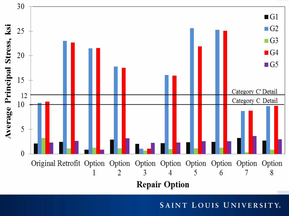
Repair Option
Brief Description
Repair Methodology / Category
1
Remove the seismic retrofit links at bent 64 in an effort to increase flexibility.
Increase Flexibility
2
Loosen the bolts at the cross-frame to stiffener plate connection to allow rotation.
Increase Flexibility
3
Provide a positive connection between the stiffener plate and the top flange.
Increase Stiffness
4
Reduce the stiffness of the “×” cross frames by 50% by removing one of the angles from the double-angle section.
Increase Flexibility
5Continue to drill 2 ⅞-in. crack arrestor holes.
Increase Flexibility
6
Remove original “K” cross frames located at the center of the spans between bents 62 and 63 and bents 63 and 64.
Increase Flexibility
7
Replace the “×” braces added as part of the seismic retrofit with the original “K” braces.
Increase Flexibility
8
Increase the web-gap length by removing a portion of the connection plate.
Increase Flexibility


![[34] - Lindquist Lablindquistlab.wi.mit.edu/wp-content/uploads/2013/06/...Schirmer, C. Queitsch, A. S. Kowal, and S. Lindquist, submitted (1997). a" Y. Sanchcz and S. L. Lindquist,](https://static.fdocuments.us/doc/165x107/606c80b19bb7de31a926ace6/34-lindquist-schirmer-c-queitsch-a-s-kowal-and-s-lindquist-submitted.jpg)