Introduction to FEM 25 · The master stiffness matrix is stored as a full symmetric matrix...
22
Introduction to FEM 25 The Assembly Process IFEM Ch 25 – Slide 1
Transcript of Introduction to FEM 25 · The master stiffness matrix is stored as a full symmetric matrix...
Introduction to FEM
25The Assembly
Process
IFEM Ch 25 – Slide 1
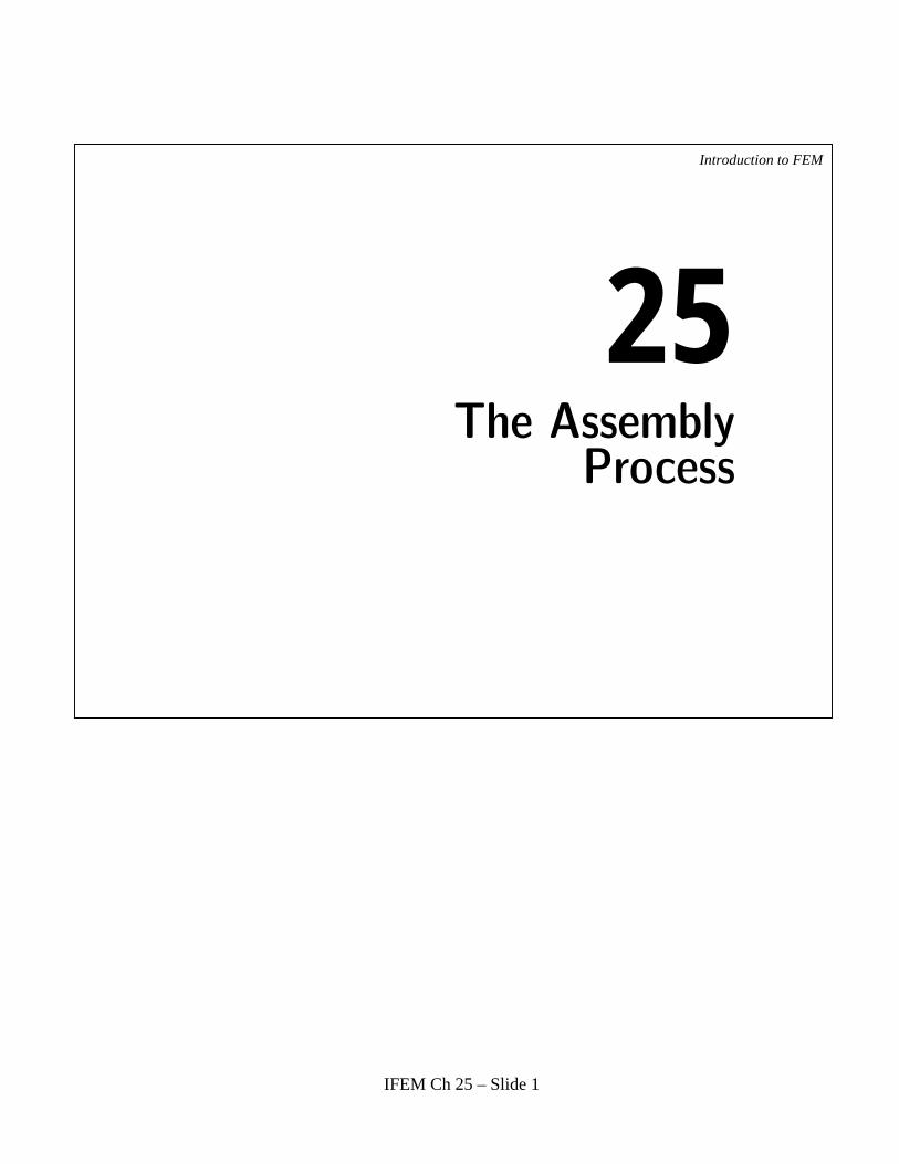
Role of the Assembler in a FEM Code
Introduction to FEM
Element Stiffness Matrices
Model definition data:geometryelement connectivity materialfabricationfreedom activity
Assembler Equation Solver
Modify Eqsfor BCs
K K
K
^
ELEMENTLIBRARY
Some equation solvers apply BCsand solve simultaneously
To postprocessor
Nodaldisplacements
mergeloop e
IFEM Ch 25 – Slide 2
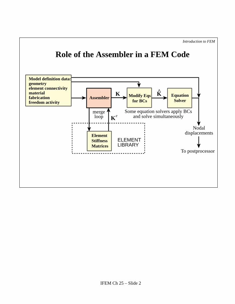
Simplified Assembly Process is Possible If
All elements are of the same type ; e.g. 2-node bars
The number and configuration of DOFs at each node is the same
There are no gaps in the node numbers
There are no multifreedom constraints (MFCs)
The master stiffness matrix is stored as a full symmetric matrix
Introduction to FEM
Restrictionsremovedin Chapter
Not addressedin Chapter
IFEM Ch 25 – Slide 3
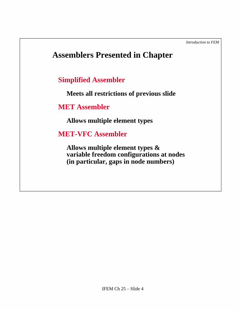
Assemblers Presented in Chapter
Simplified Assembler
Meets all restrictions of previous slide
MET Assembler
Allows multiple element types
MET-VFC Assembler
Allows multiple element types & variable freedom configurations at nodes (in particular, gaps in node numbers)
Introduction to FEM
IFEM Ch 25 – Slide 4
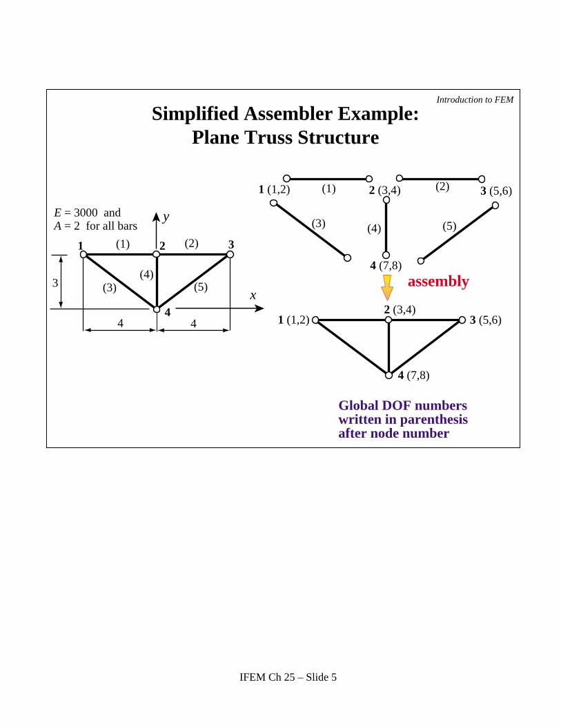
Simplified Assembler Example: Plane Truss Structure
1 (1,2)
1 (1,2)
(1) (2)
(3) (4) (5)
4 (7,8)
4 (7,8)
2 (3,4)
2 (3,4)
3 (5,6)
3 (5,6)
assembly3x
y
4 4
(1) (2)
(3)(4)
(5)
1 2 3
4
E = 3000 and A = 2 for all bars
Global DOF numberswritten in parenthesisafter node number
Introduction to FEM
IFEM Ch 25 – Slide 5
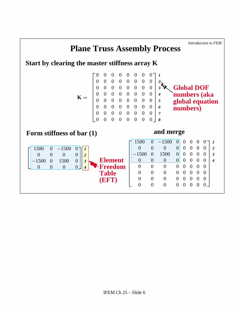
Plane Truss Assembly Process
K =
0 0 0 0 0 0 0 00 0 0 0 0 0 0 00 0 0 0 0 0 0 00 0 0 0 0 0 0 00 0 0 0 0 0 0 00 0 0 0 0 0 0 00 0 0 0 0 0 0 00 0 0 0 0 0 0 0
1
2
3
4
5
6
7
8
Start by clearing the master stiffness array K
Global DOFnumbers (akaglobal equationnumbers)
Form stiffness of bar (1) and merge
1500 0 −1500 00 0 0 0
−1500 0 1500 00 0 0 0
1
2
3
4
1500 0 −1500 0 0 0 0 00 0 0 0 0 0 0 0
−1500 0 1500 0 0 0 0 00 0 0 0 0 0 0 00 0 0 0 0 0 0 00 0 0 0 0 0 0 00 0 0 0 0 0 0 00 0 0 0 0 0 0 0
1
2
3
4
Introduction to FEM
Element Freedom Table (EFT)
IFEM Ch 25 – Slide 6
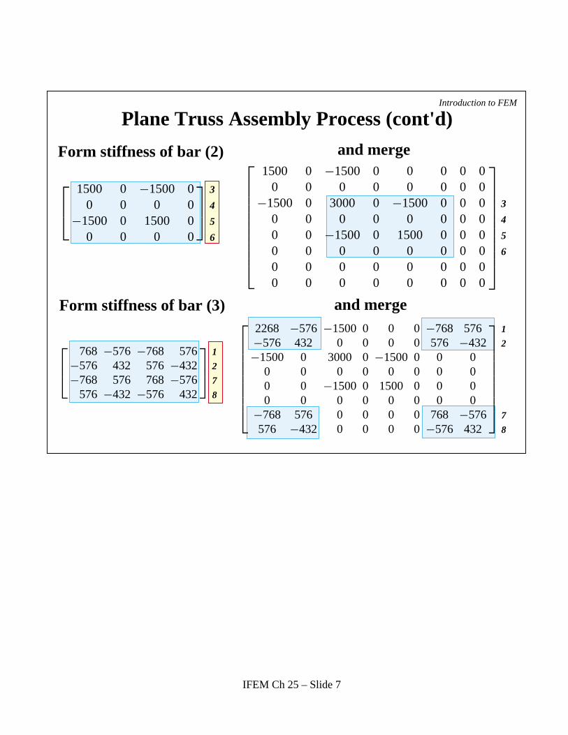
Plane Truss Assembly Process (cont'd)
Form stiffness of bar (2)
Form stiffness of bar (3)
and merge
and merge
1500 0 −1500 00 0 0 0
−1500 0 1500 00 0 0 0
3
4
5
6
1500 0 −1500 0 0 0 0 00 0 0 0 0 0 0 0
−1500 0 3000 0 −1500 0 0 00 0 0 0 0 0 0 00 0 −1500 0 1500 0 0 00 0 0 0 0 0 0 00 0 0 0 0 0 0 00 0 0 0 0 0 0 0
3
4
5
6
Introduction to FEM
768 −576 −768 576−576 432 576 −432−768 576 768 −576
576 −432 −576 432
1
2
7
8
2268 −576 −1500 0 0 0 −768 576−576 432 0 0 0 0 576 −432−1500 0 3000 0 −1500 0 0 0
0 0 0 0 0 0 0 00 0 −1500 0 1500 0 0 00 0 0 0 0 0 0 0
−768 576 0 0 0 0 768 −576576 −432 0 0 0 0 −576 432
1
2
7
8
IFEM Ch 25 – Slide 7
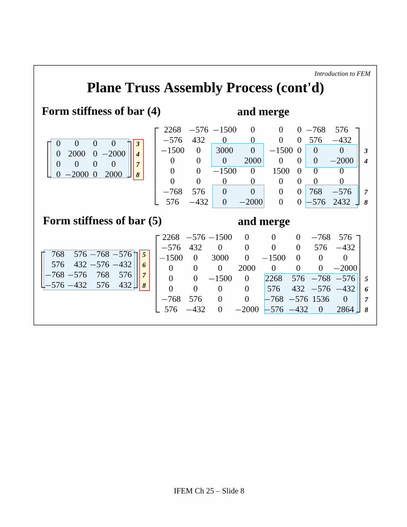
Plane Truss Assembly Process (cont'd)
Form stiffness of bar (4)
Form stiffness of bar (5)
and merge
and merge
Introduction to FEM
0 0 0 00 2000 0 −20000 0 0 00 −2000 0 2000
3
4
7
8
2268 −576 −1500 0 0 0 −768 576−576 432 0 0 0 0 576 −432−1500 0 3000 0 −1500 0 0 0
0 0 0 2000 0 0 0 −20000 0 −1500 0 1500 0 0 00 0 0 0 0 0 0 0
−768 576 0 0 0 0 768 −576576 −432 0 −2000 0 0 −576 2432
3
4
7
8
768 576 −768 −576576 432 −576 −432
−768 −576 768 576−576 −432 576 432
5
6
7
8
2268 −576 −1500 0 0 0 −768 576−576 432 0 0 0 0 576 −432−1500 0 3000 0 −1500 0 0 0
0 0 0 2000 0 0 0 −20000 0 −1500 0 2268 576 −768 −5760 0 0 0 576 432 −576 −432
−768 576 0 0 −768 −576 1536 0576 −432 0 −2000 −576 −432 0 2864
5
6
7
8
IFEM Ch 25 – Slide 8
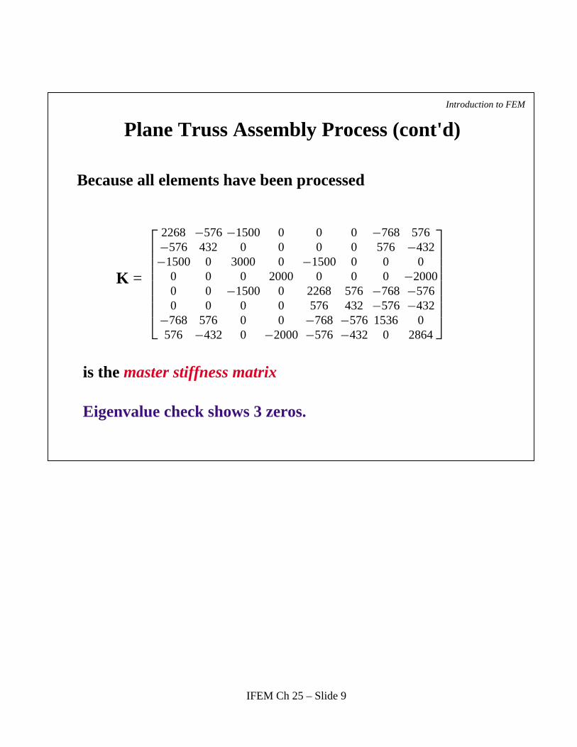
Plane Truss Assembly Process (cont'd)
Because all elements have been processed
is the master stiffness matrix
Eigenvalue check shows 3 zeros.
Introduction to FEM
2268 −576 −1500 0 0 0 −768 576−576 432 0 0 0 0 576 −432−1500 0 3000 0 −1500 0 0 0
0 0 0 2000 0 0 0 −20000 0 −1500 0 2268 576 −768 −5760 0 0 0 576 432 −576 −432
−768 576 0 0 −768 −576 1536 0576 −432 0 −2000 −576 −432 0 2864
K =
IFEM Ch 25 – Slide 9
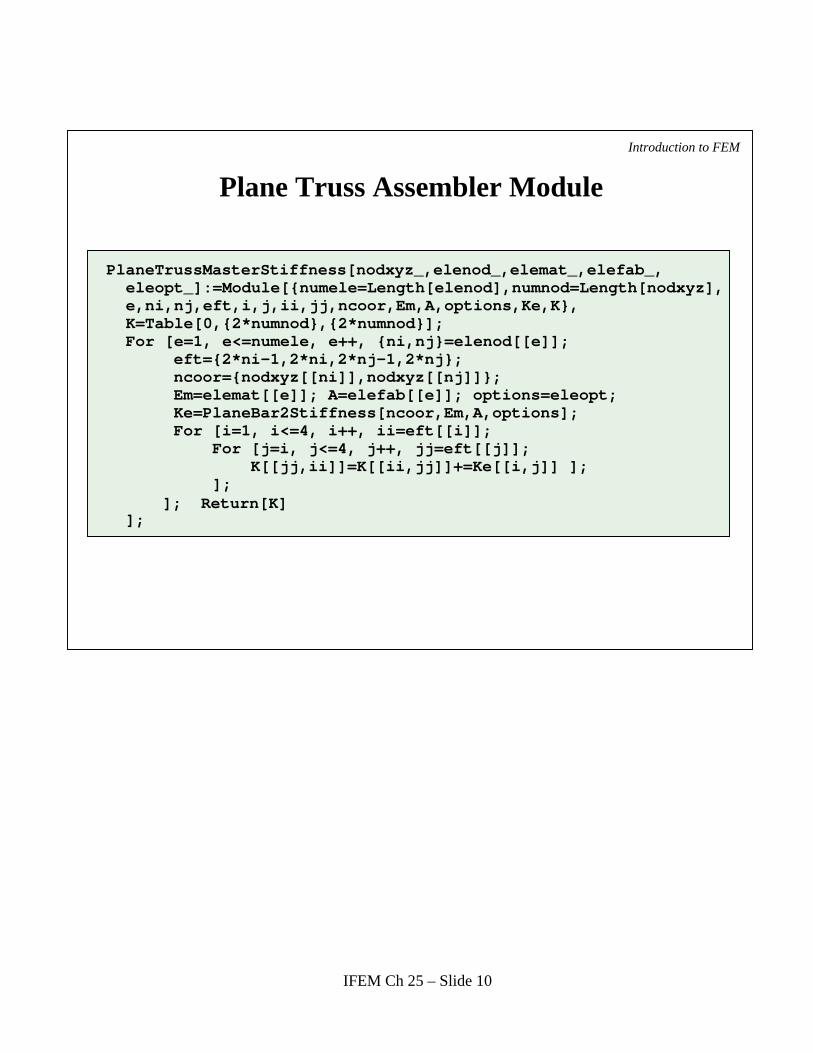
Plane Truss Assembler Module
Introduction to FEM
PlaneTrussMasterStiffness[nodxyz_,elenod_,elemat_,elefab_, eleopt_]:=Module[{numele=Length[elenod],numnod=Length[nodxyz], e,ni,nj,eft,i,j,ii,jj,ncoor,Em,A,options,Ke,K}, K=Table[0,{2*numnod},{2*numnod}]; For [e=1, e<=numele, e++, {ni,nj}=elenod[[e]]; eft={2*ni-1,2*ni,2*nj-1,2*nj}; ncoor={nodxyz[[ni]],nodxyz[[nj]]}; Em=elemat[[e]]; A=elefab[[e]]; options=eleopt; Ke=PlaneBar2Stiffness[ncoor,Em,A,options]; For [i=1, i<=4, i++, ii=eft[[i]]; For [j=i, j<=4, j++, jj=eft[[j]]; K[[jj,ii]]=K[[ii,jj]]+=Ke[[i,j]] ]; ]; ]; Return[K] ];
IFEM Ch 25 – Slide 10
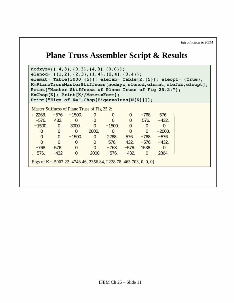
Plane Truss Assembler Script & Results
Introduction to FEM
nodxyz={{-4,3},{0,3},{4,3},{0,0}};elenod= {{1,2},{2,3},{1,4},{2,4},{3,4}};elemat= Table[3000,{5}]; elefab= Table[2,{5}]; eleopt= {True};K=PlaneTrussMasterStiffness[nodxyz,elenod,elemat,elefab,eleopt]; Print["Master Stiffness of Plane Truss of Fig 25.2:"];K=Chop[K]; Print[K//MatrixForm];Print["Eigs of K=",Chop[Eigenvalues[N[K]]]];
2268. −576. −1500. 0 0 0 −768. 576.−576. 432. 0 0 0 0 576. −432.−1500. 0 3000. 0 −1500. 0 0 0
0 0 0 2000. 0 0 0 −2000.0 0 −1500. 0 2268. 576. −768. −576.0 0 0 0 576. 432. −576. −432.
−768. 576. 0 0 −768. −576. 1536. 0576. −432. 0 −2000. −576. −432. 0 2864.
Eigs of K={5007.22, 4743.46, 2356.84, 2228.78, 463.703, 0, 0, 0}
Master Stiffness of Plane Truss of Fig 25.2:
IFEM Ch 25 – Slide 11
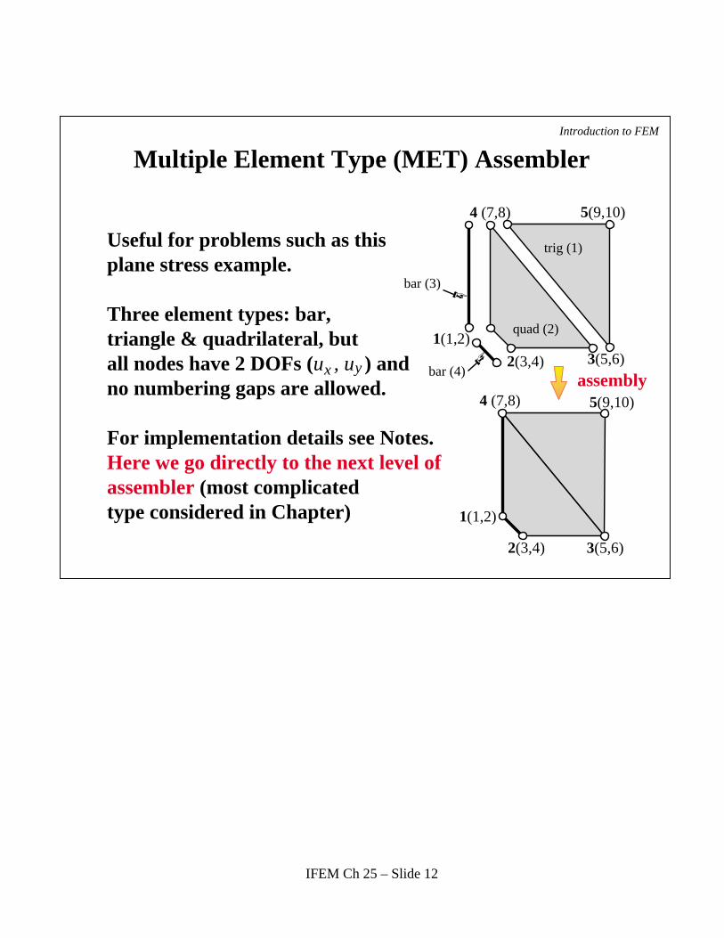
Multiple Element Type (MET) AssemblerIntroduction to FEM
bar (4)
1(1,2)
1(1,2)
3(5,6)
3(5,6)
4 (7,8)
4 (7,8)
5(9,10)
5(9,10)
2(3,4)
2(3,4)
assembly
Useful for problems such as thisplane stress example.
Three element types: bar,triangle & quadrilateral, butall nodes have 2 DOFs (u , u ) and no numbering gaps are allowed.
For implementation details see Notes.Here we go directly to the next level ofassembler (most complicatedtype considered in Chapter)
quad (2)
trig (1)
bar (3)
x y
IFEM Ch 25 – Slide 12
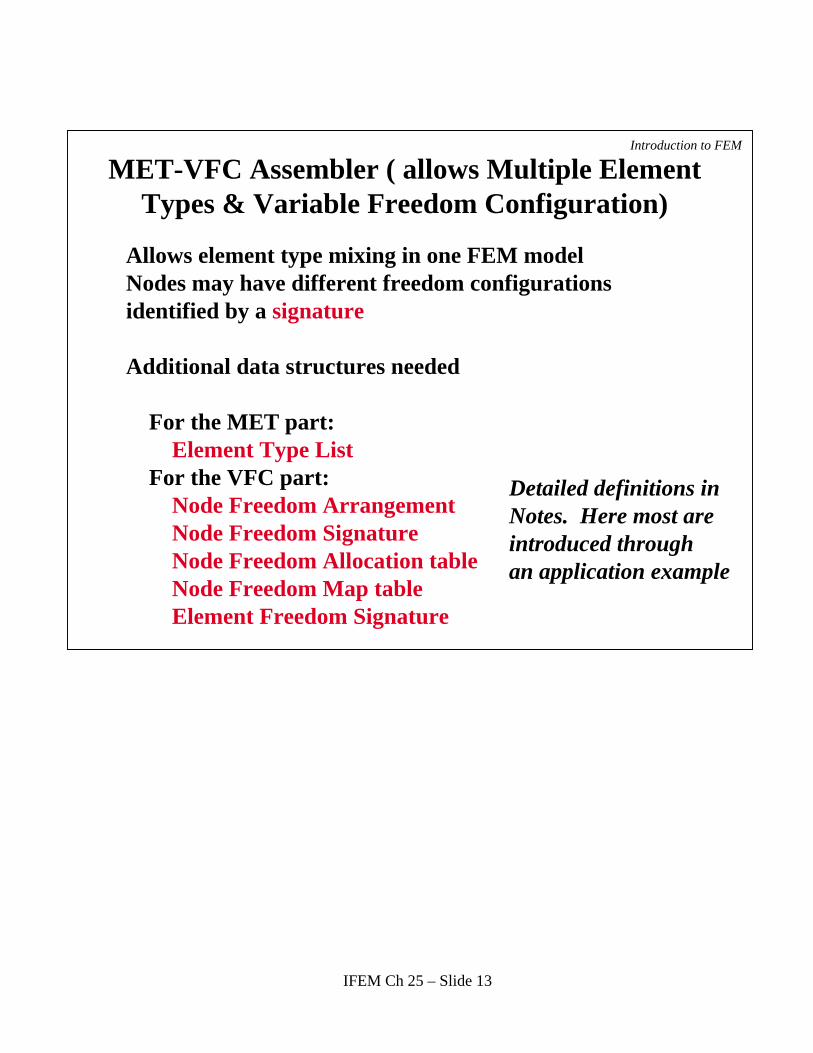
MET-VFC Assembler ( allows Multiple Element Types & Variable Freedom Configuration)
Introduction to FEM
Allows element type mixing in one FEM modelNodes may have different freedom configurations identified by a signature
Additional data structures needed For the MET part: Element Type List For the VFC part: Node Freedom Arrangement Node Freedom Signature Node Freedom Allocation table Node Freedom Map table Element Freedom Signature
Detailed definitions inNotes. Here most areintroduced throughan application example
IFEM Ch 25 – Slide 13

Trussed Frame Structure to Illustrate MET-VFC Assembly
Introduction to FEM
3 m
E=200000 MPa A=0.003 m2
E=200000 MPa A=0.001 m 2
E=200000 MPa A=0.001 m2
2E=30000 MPa, A=0.02 m , I =0.0004 m4zz
4 m 4 m
x
y
FEM idealization
(node 4: undefined)
Two element types:Beam-column & bar
Nodes 1, 3 and 5have 3 DOFs each
Node 2 has 2 DOF
Node 4 is notdefined (numbering gap)
Bar (3)
Bar (4)
Bar (5)
1
2
53Beam-column (1)
Beam-column (2)
IFEM Ch 25 – Slide 14
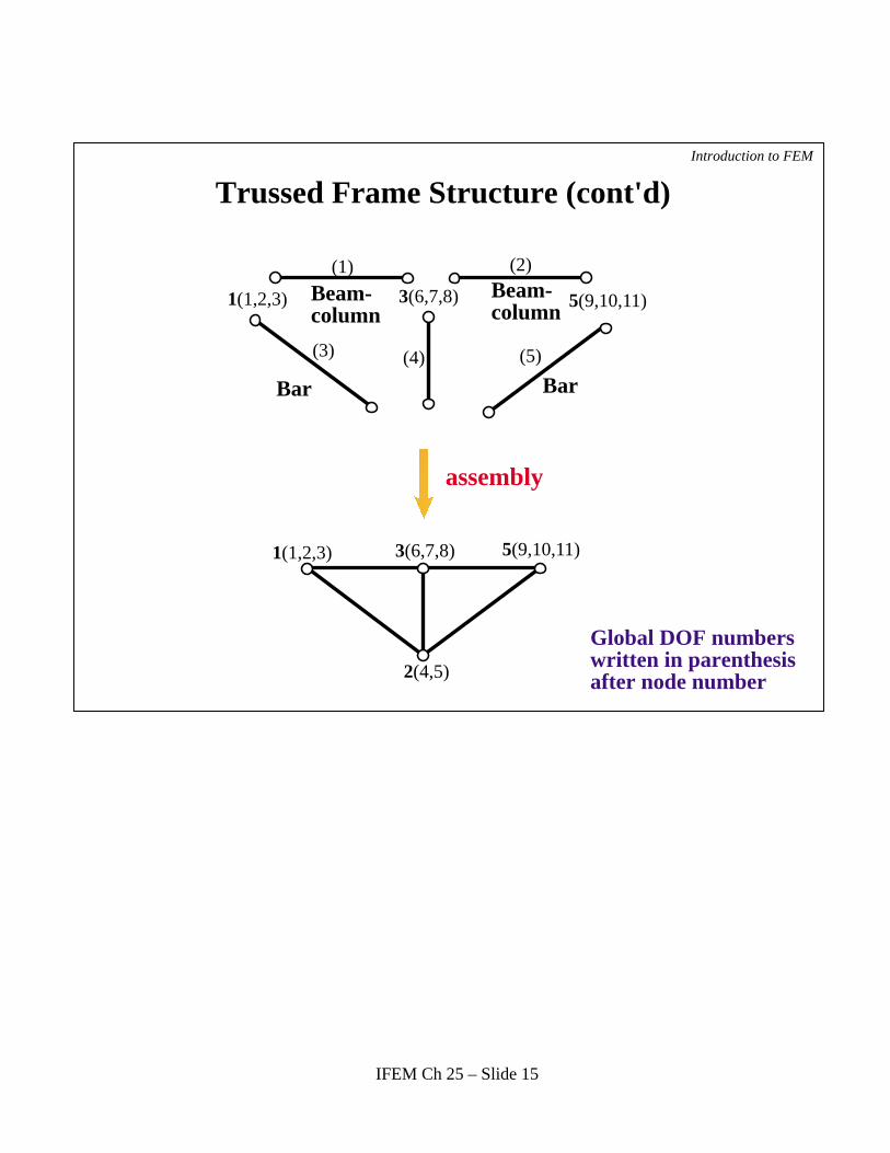
Trussed Frame Structure (cont'd)Introduction to FEM
1(1,2,3)
1(1,2,3)
3(6,7,8)
3(6,7,8)
5(9,10,11)
5(9,10,11)
2(4,5)
assembly
(1) (2)
(3) (4) (5)
Beam-column
Beam-column
Bar Bar
Global DOF numberswritten in parenthesisafter node number
IFEM Ch 25 – Slide 15
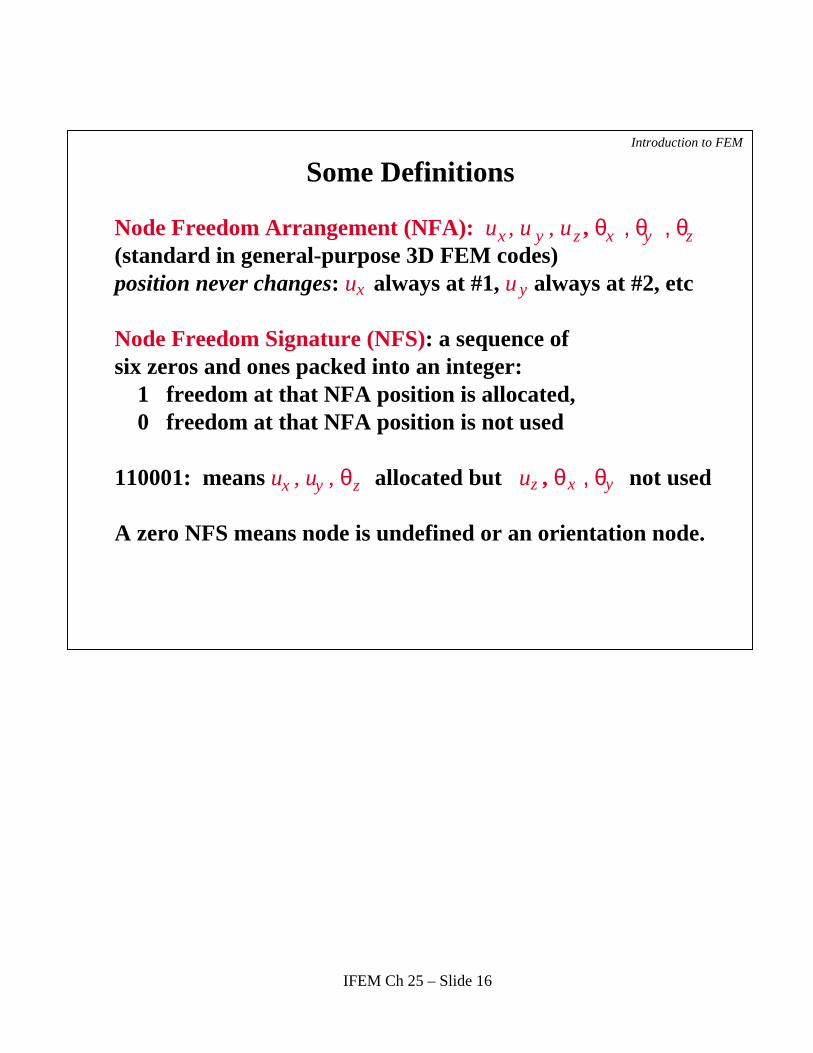
Some DefinitionsIntroduction to FEM
Node Freedom Arrangement (NFA): u , u , u , θ , θ , θ(standard in general-purpose 3D FEM codes)position never changes: u always at #1, u always at #2, etc
Node Freedom Signature (NFS): a sequence ofsix zeros and ones packed into an integer: 1 freedom at that NFA position is allocated, 0 freedom at that NFA position is not used
110001: means u , u , θ allocated but u , θ , θ not used
A zero NFS means node is undefined or an orientation node.
x y z x y z
z x y x y z
x y
IFEM Ch 25 – Slide 16
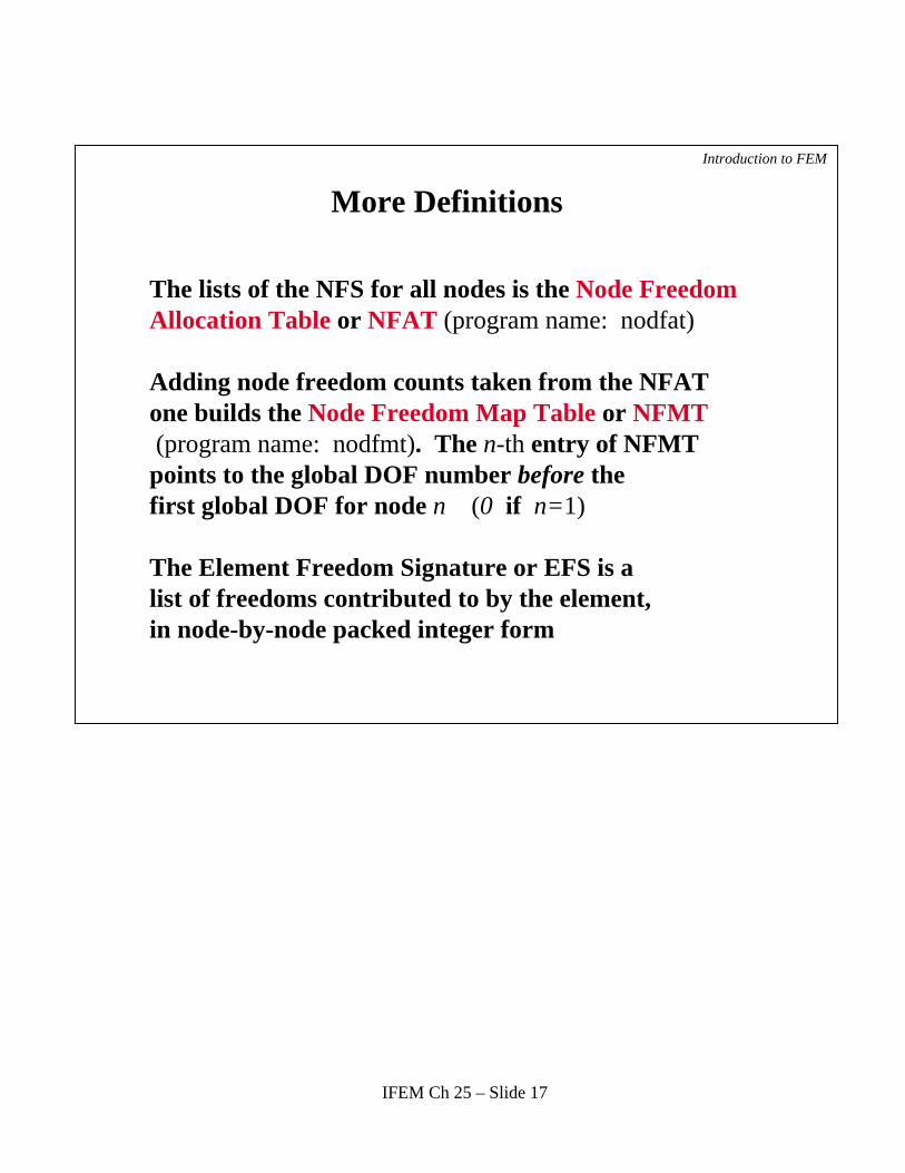
More Definitions
Introduction to FEM
The lists of the NFS for all nodes is the Node FreedomAllocation Table or NFAT (program name: nodfat)
Adding node freedom counts taken from the NFATone builds the Node Freedom Map Table or NFMT (program name: nodfmt). The n-th entry of NFMTpoints to the global DOF number before thefirst global DOF for node n (0 if n=1)
The Element Freedom Signature or EFS is a list of freedoms contributed to by the element,in node-by-node packed integer form
IFEM Ch 25 – Slide 17
Introduction to FEM
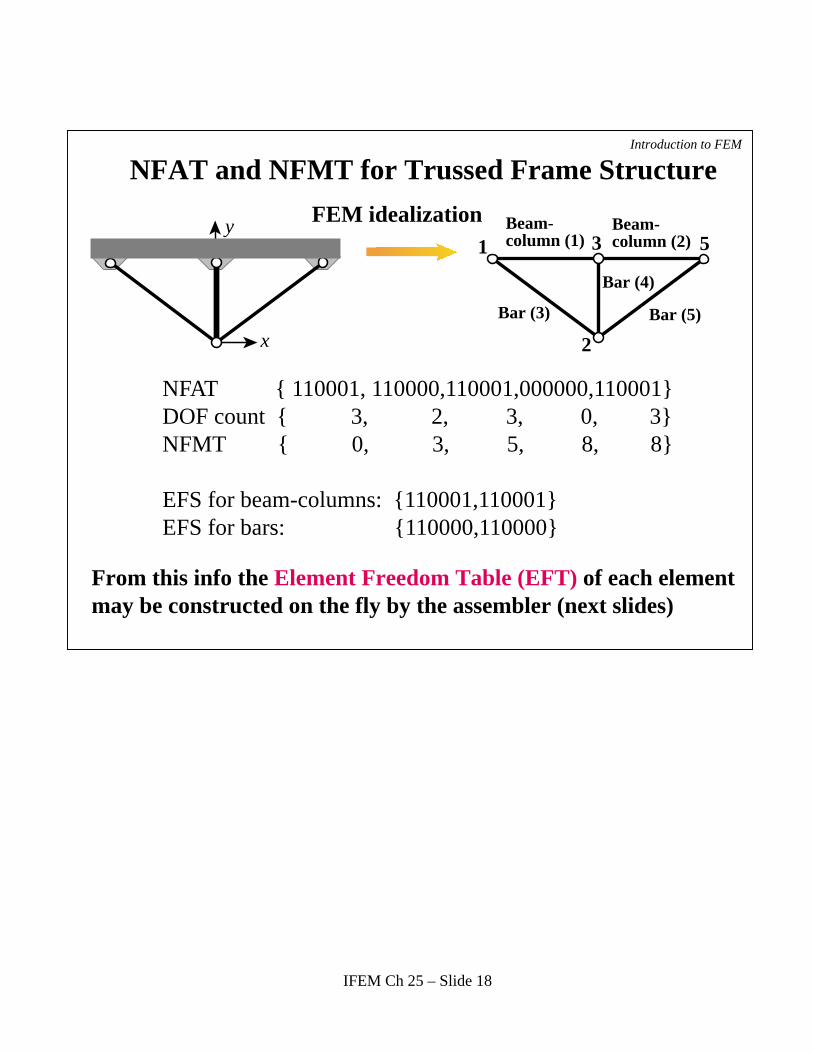
NFAT { 110001, 110000,110001,000000,110001}DOF count { 3, 2, 3, 0, 3} NFMT { 0, 3, 5, 8, 8}
EFS for beam-columns: {110001,110001}EFS for bars: {110000,110000}
x
y
Bar (3)
Bar (4)
Bar (5)
1
2
53FEM idealization Beam-
column (1)Beam-column (2)
NFAT and NFMT for Trussed Frame Structure
From this info the Element Freedom Table (EFT) of each elementmay be constructed on the fly by the assembler (next slides)
IFEM Ch 25 – Slide 18
Introduction to FEM
x
y
Bar (3)
Bar (4)
Bar (5)
1
2
53FEM idealization Beam-
column (1)Beam-column (2)
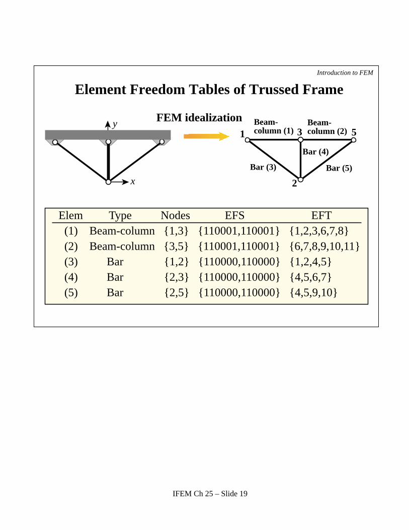
Element Freedom Tables of Trussed Frame
Elem Type Nodes EFS EFT (1) Beam-column {1,3} {110001,110001} {1,2,3,6,7,8} (2) Beam-column {3,5} {110001,110001} {6,7,8,9,10,11} (3) Bar {1,2} {110000,110000} {1,2,4,5} (4) Bar {2,3} {110000,110000} {4,5,6,7} (5) Bar {2,5} {110000,110000} {4,5,9,10}
IFEM Ch 25 – Slide 19
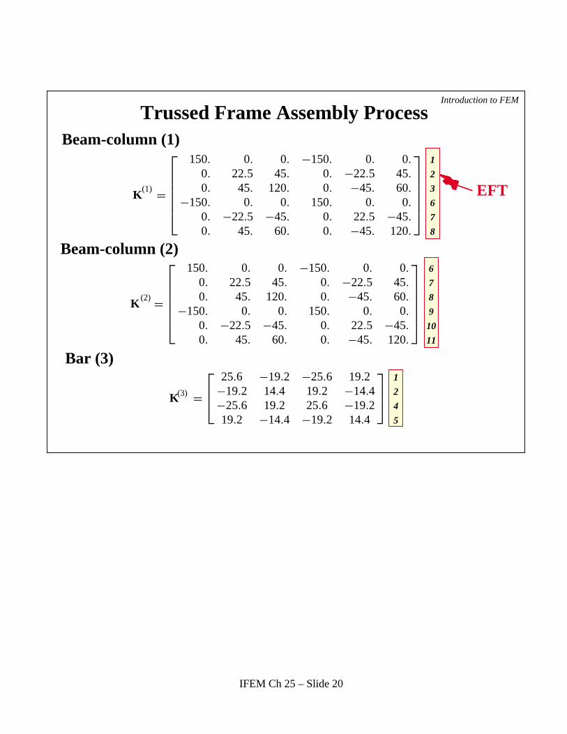
Trussed Frame Assembly ProcessIntroduction to FEM
K =
150. 0. 0. −150. 0. 0.
0. 22.5 45. 0. −22.5 45.
0. 45. 120. 0. −45. 60.
−150. 0. 0. 150. 0. 0.
0. −22.5 −45. 0. 22.5 −45.
0. 45. 60. 0. −45. 120.
1
2
3
6
7
8
K =
150. 0. 0. −150. 0. 0.
0. 22.5 45. 0. −22.5 45.
0. 45. 120. 0. −45. 60.
−150. 0. 0. 150. 0. 0.
0. −22.5 −45. 0. 22.5 −45.
0. 45. 60. 0. −45. 120.
6
7
8
9
10
11
K =
25.6 −19.2 −25.6 19.2−19.2 14.4 19.2 −14.4−25.6 19.2 25.6 −19.219.2 −14.4 −19.2 14.4
1
2
4
5
Beam-column (1)
Beam-column (2)
Bar (3)
EFT
(3)
(2)
(1)
IFEM Ch 25 – Slide 20

Trussed Frame Assembly Process (cont'd)Introduction to FEM
Bar (4)
Bar (5)
Master Stiffness Matrix
K =
0 0 0 00 200. 0 −200.
0 0 0 00 −200. 0 200.
4
5
6
7
K =
25.6 19.2 −25.6 −19.219.2 14.4 −19.2 −14.4
−25.6 −19.2 25.6 19.2−19.2 −14.4 19.2 14.4
4
5
9
10
K =
175.6 −19.2 0 −25.6 19.2 −150. 0 0 0 0 0−19.2 36.9 45. 19.2 −14.4 0 −22.5 45. 0 0 0
0 45. 120. 0 0 0 −45. 60. 0 0 0−25.6 19.2 0 51.2 0 0 0 0 −25.6 −19.2 0
19.2 −14.4 0 0 228.8 0 −200. 0 −19.2 −14.4 0−150. 0 0 0 0 300. 0 0 −150. 0 0
0 −22.5 −45. 0 −200. 0 245. 0 0 −22.5 45.
0 45. 60. 0 0 0 0 240. 0 −45. 60.
0 0 0 −25.6 −19.2 −150. 0 0 175.6 19.2 00 0 0 −19.2 −14.4 0 −22.5 −45. 19.2 36.9 −45.
0 0 0 0 0 0 45. 60. 0 −45. 120.
1
2
3
4
5
6
7
8
9
10
11
EFT
(5)
(4)
IFEM Ch 25 – Slide 21
Introduction to FEM
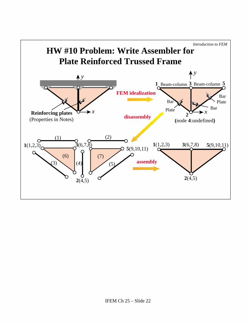
Plate
(6) (7)
BarBar
Bar
1
1(1,2,3)1(1,2,3)
2
3(6,7,8)3(6,7,8)
5
5(9,10,11)5(9,10,11)
3
2(4,5) 2(4,5)
disassembly
assembly
FEM idealization
(1) (2)
(3) (4) (5)
Beam-column Beam-column
(node 4:undefined)
x
y
x
y
Plate
(Properties in Notes)
HW #10 Problem: Write Assembler for Plate Reinforced Trussed Frame
Reinforcing plates
IFEM Ch 25 – Slide 22