FEM Modeling and Weight Reduction of a Solar Energy Driven ...
1http://www.midasnfx.com Introduction to FEM Modeling
Introduction to FEM Modeling
Apoorv Sharmamidas NFX
CAE Consultant
Total Analysis Solution for Multi-disciplinary Optimum Design
2http://www.midasnfx.com Introduction to FEM Modeling
Introduction to FEM Modeling
1. Introduction
2. Element Types
3. Sample Exercise: 1D Modeling
4. Meshing Tools
5. Loads and Boundary Conditions
6. Sample Exercise 2: Bracket
3http://www.midasnfx.com Introduction to FEM Modeling
Objective of Today’s Webinar
Introduction01
• Identify the important aspects of FE modeling.
• Understand the application aspects of different element types in practical FEA.
• Get acquainted with tools available for effective FE modeling in Midas NFX.
• Know the importance of loads and boundary conditions.
• Understand the NFX workflow for modeling an FE problem via live example.
4http://www.midasnfx.com Introduction to FEM Modeling
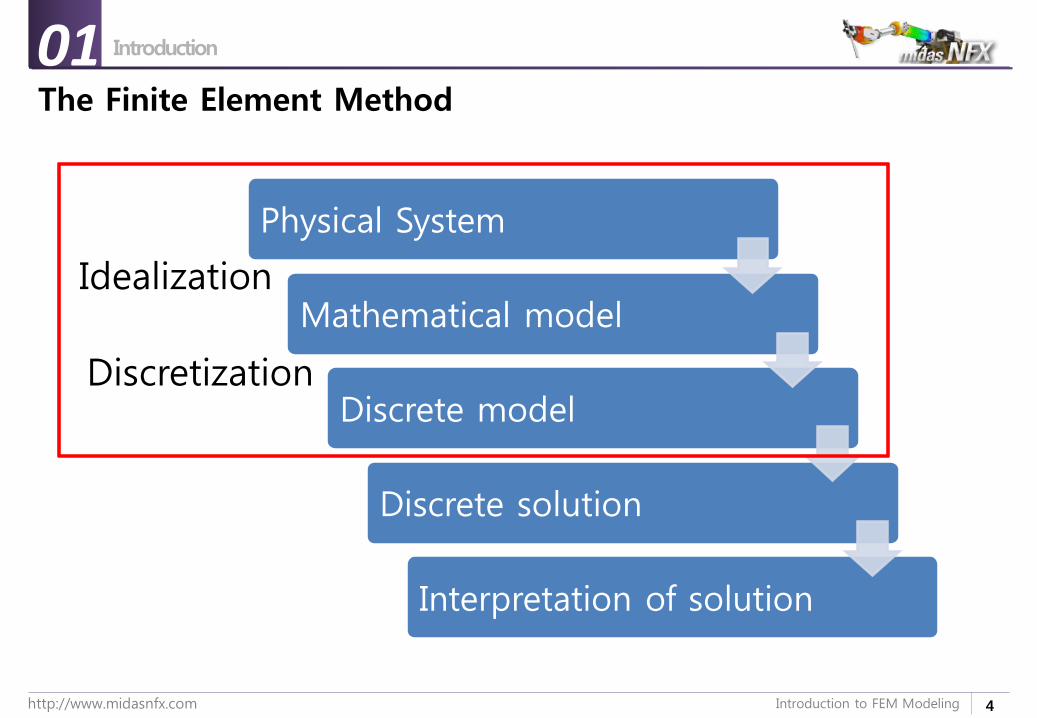
The Finite Element Method
Introduction01
Physical System
Mathematical model
Discrete model
Discrete solution
Interpretation of solution
Idealization
Discretization
5http://www.midasnfx.com Introduction to FEM Modeling
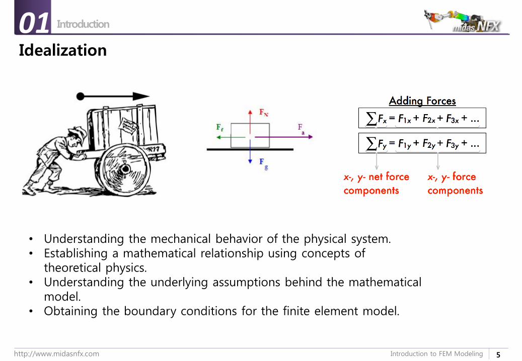
Idealization
Introduction01
• Understanding the mechanical behavior of the physical system.• Establishing a mathematical relationship using concepts of
theoretical physics.• Understanding the underlying assumptions behind the mathematical
model.• Obtaining the boundary conditions for the finite element model.
6http://www.midasnfx.com Introduction to FEM Modeling
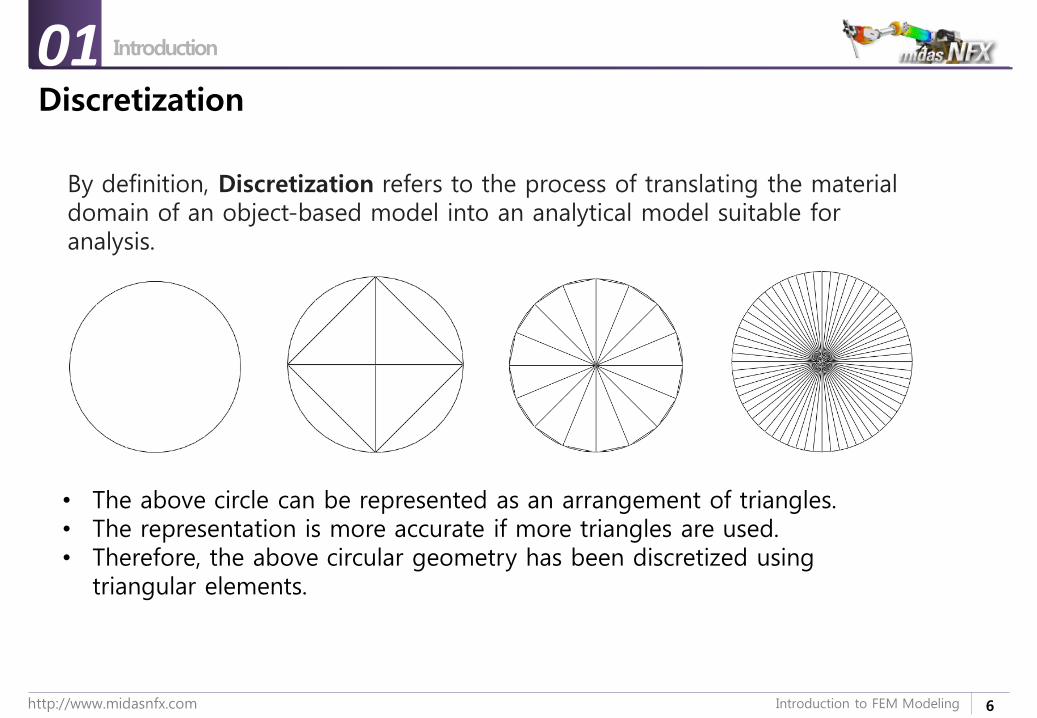
Discretization
Introduction01
• The above circle can be represented as an arrangement of triangles.• The representation is more accurate if more triangles are used.• Therefore, the above circular geometry has been discretized using
triangular elements.
By definition, Discretization refers to the process of translating the material domain of an object-based model into an analytical model suitable for analysis.
9http://www.midasnfx.com Introduction to FEM Modeling
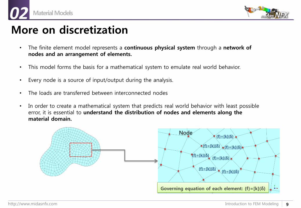
More on discretization
Material Models02
• The finite element model represents a continuous physical system through a network of nodes and an arrangement of elements.
• This model forms the basis for a mathematical system to emulate real world behavior.
• Every node is a source of input/output during the analysis.
• The loads are transferred between interconnected nodes
• In order to create a mathematical system that predicts real world behavior with least possible error, it is essential to understand the distribution of nodes and elements along the material domain.
Node
{f}=[k]{δ}
{f}=[k]{δ}
{f}=[k]{δ}
{f}=[k]{δ}
{f}=[k]{δ}
{f}=[k]{δ}{f}=[k]{δ}
Governing equation of each element: {f}=[k]{δ}

12http://www.midasnfx.com Introduction to FEM Modeling
Importance of Engineering judgment
Material Models02
• What kind of behavior is essential to analyze to investigate this problem (linear, nonlinear, static, dynamic, steady, transient etc.)?
• What type of elements should be used?
• Does the finite element model effectively represent the physics of the system?
• Does it comply with the theoretical assumptions?
• Is the best available method in terms of time & cost-effectiveness?
• If not, are there any practical, economical and effective alternatives?
• How much percentage error can we account for, by adopting the more practical alternative?
13http://www.midasnfx.com Introduction to FEM Modeling
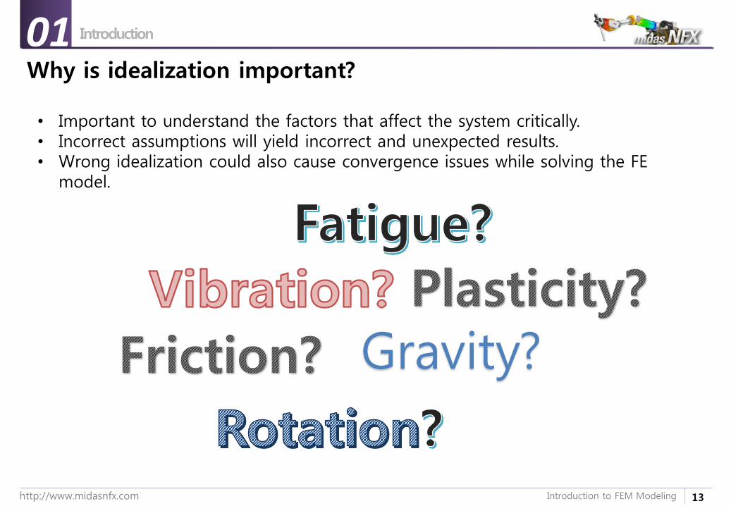
Why is idealization important?
Introduction01
• Important to understand the factors that affect the system critically.• Incorrect assumptions will yield incorrect and unexpected results.• Wrong idealization could also cause convergence issues while solving the FE
model.
Gravity?
14http://www.midasnfx.com Introduction to FEM Modeling
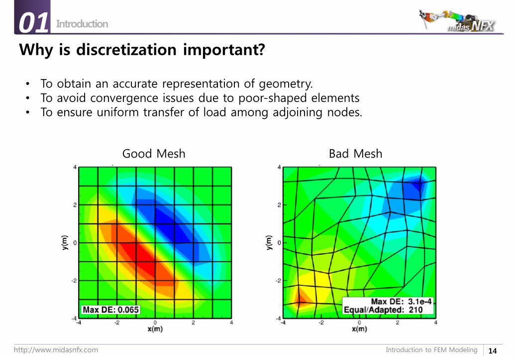
Why is discretization important?
Introduction01
• To obtain an accurate representation of geometry.• To avoid convergence issues due to poor-shaped elements• To ensure uniform transfer of load among adjoining nodes.
Good Mesh Bad Mesh
19http://www.midasnfx.com Introduction to FEM Modeling
Introduction to FEM Modeling
1. Introduction
2. Element Types
3. Sample Exercise: 1D Modeling
4. Meshing Tools
5. Loads and Boundary Conditions
6. Sample Exercise: Bracket
20http://www.midasnfx.com Introduction to FEM Modeling
Element Types
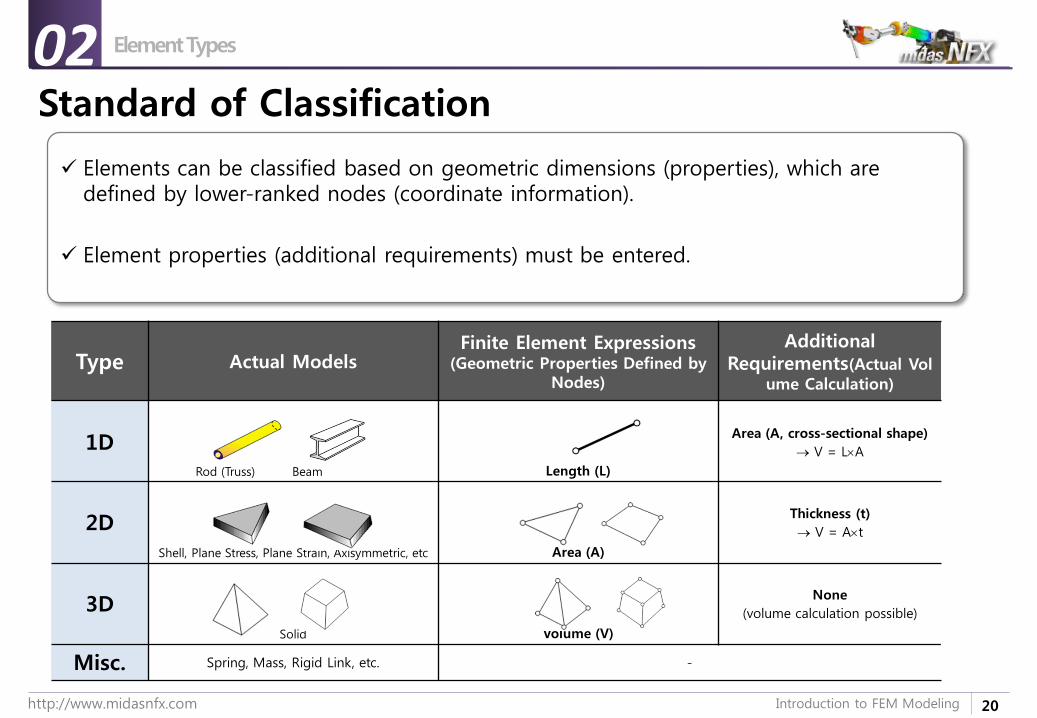
Standard of Classification
Elements can be classified based on geometric dimensions (properties), which are defined by lower-ranked nodes (coordinate information).
Element properties (additional requirements) must be entered.
Type Actual ModelsFinite Element Expressions
(Geometric Properties Defined by Nodes)
Additional Requirements(Actual Vol
ume Calculation)
1DRod (Truss) Beam Length (L)
Area (A, cross-sectional shape)
V = LA
2D
Shell, Plane Stress, Plane Strain, Axisymmetric, etc Area (A)
Thickness (t)
V = At
3D
Solid Volume (V)
None
(volume calculation possible)
Misc. Spring, Mass, Rigid Link, etc. -
02
21http://www.midasnfx.com Introduction to FEM Modeling
Element Types
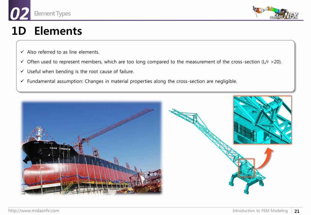
1D Elements
Also referred to as line elements.
Often used to represent members, which are too long compared to the measurement of the cross-section (L/r >20).
Useful when bending is the root cause of failure.
Fundamental assumption: Changes in material properties along the cross-section are negligible.
02
23http://www.midasnfx.com Introduction to FEM Modeling
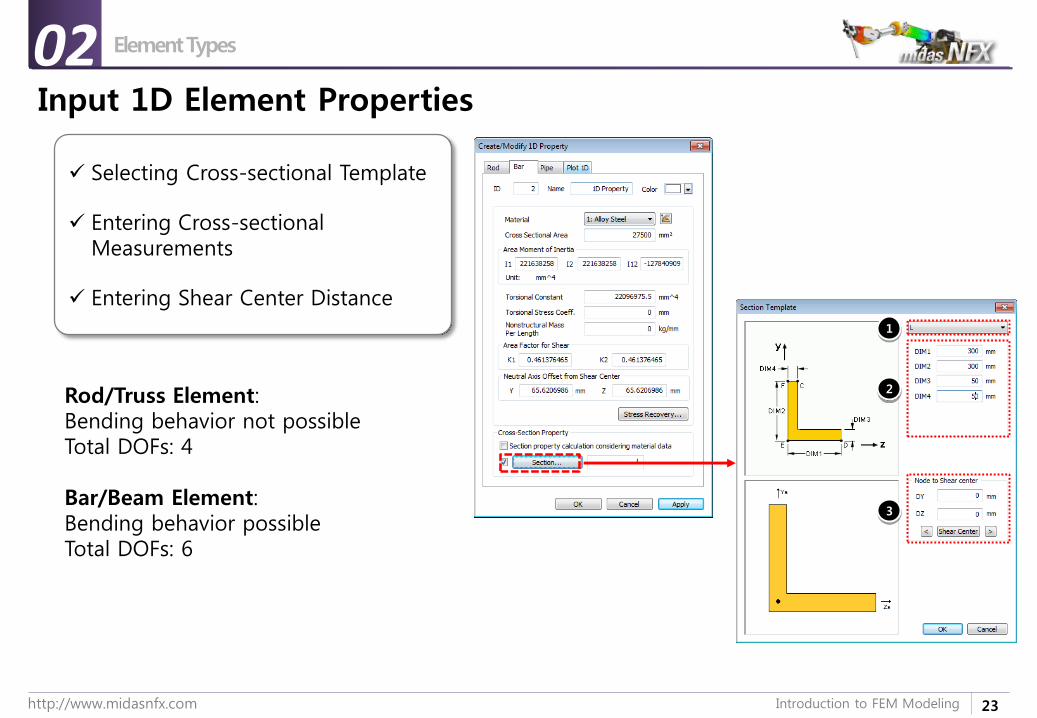
Input 1D Element Properties
Selecting Cross-sectional Template
Entering Cross-sectional Measurements
Entering Shear Center Distance
1
2
3
Element Types02
Rod/Truss Element:Bending behavior not possibleTotal DOFs: 4
Bar/Beam Element:Bending behavior possibleTotal DOFs: 6
24http://www.midasnfx.com Introduction to FEM Modeling
Element Types
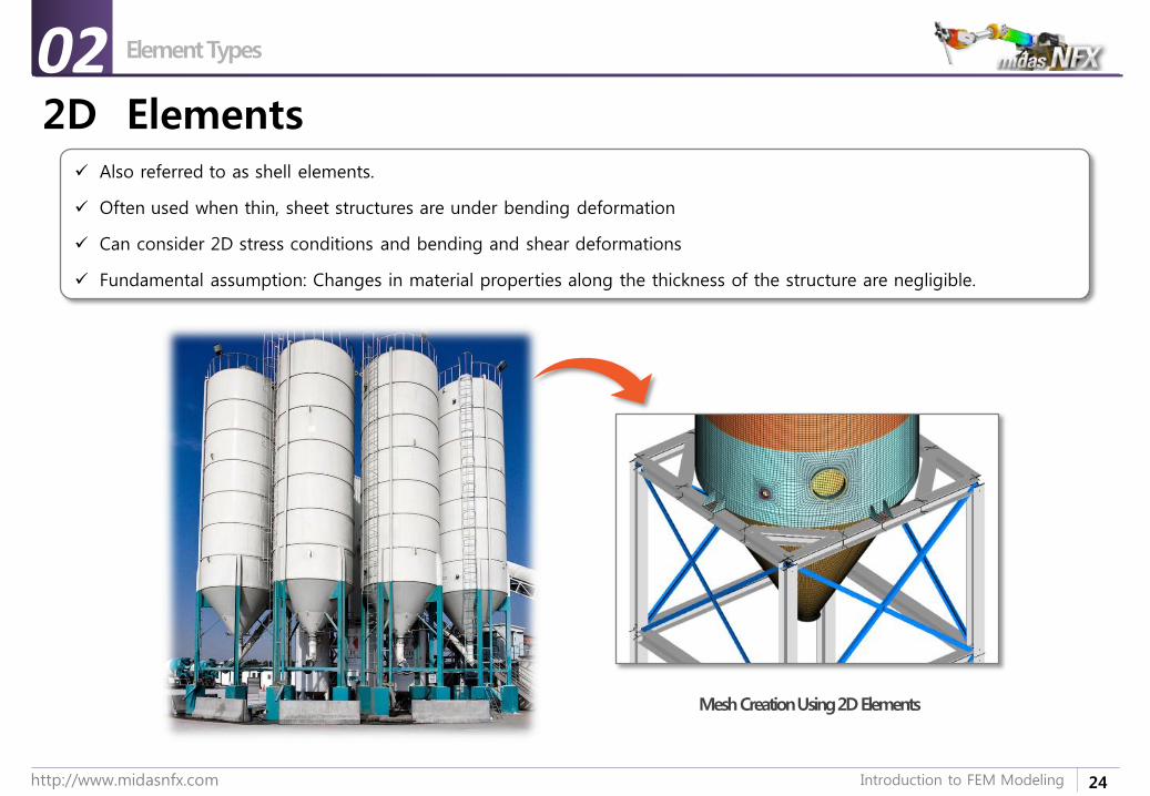
2D Elements Also referred to as shell elements.
Often used when thin, sheet structures are under bending deformation
Can consider 2D stress conditions and bending and shear deformations
Fundamental assumption: Changes in material properties along the thickness of the structure are negligible.
Mesh Creation Using 2D Elements
02
26http://www.midasnfx.com Introduction to FEM Modeling
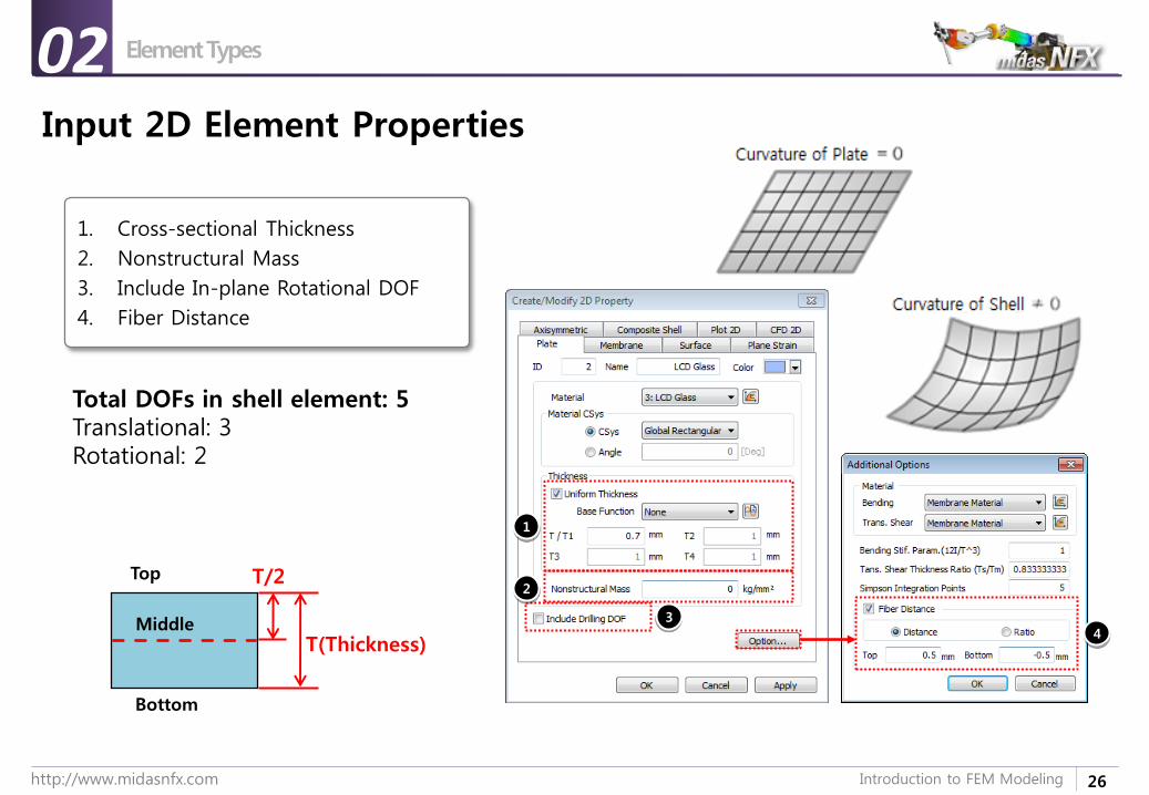
Input 2D Element Properties
1. Cross-sectional Thickness
2. Nonstructural Mass
3. Include In-plane Rotational DOF
4. Fiber Distance
Top
Bottom
Middle
T/2
T(Thickness)
1
2
34
Element Types02
Total DOFs in shell element: 5Translational: 3Rotational: 2
27http://www.midasnfx.com Introduction to FEM Modeling
Element Types
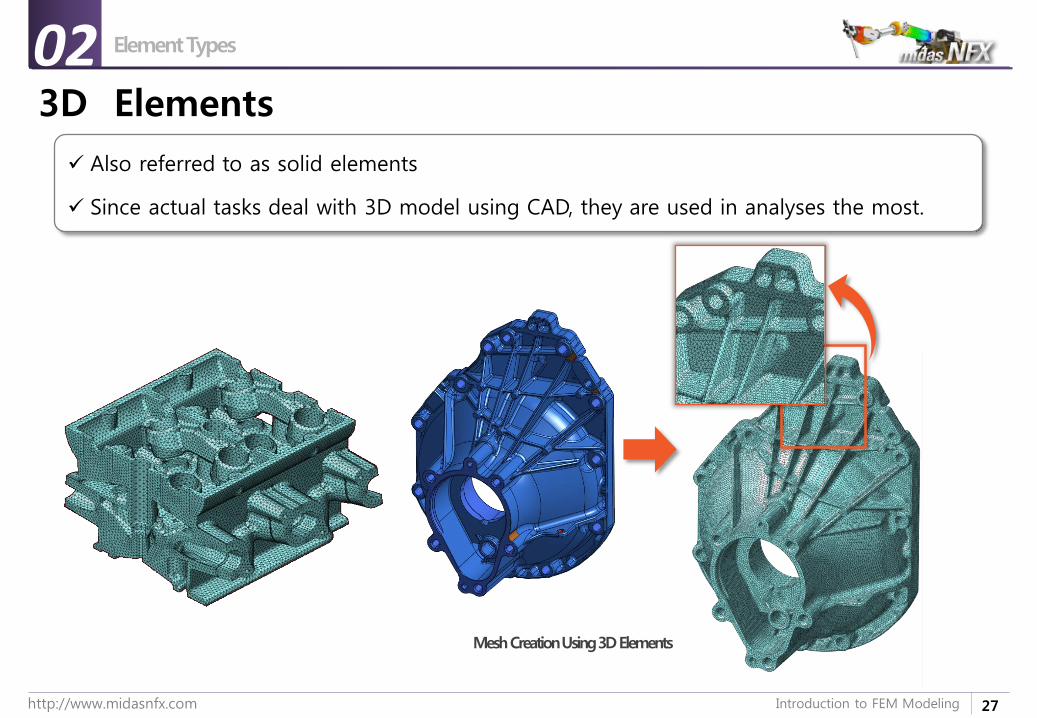
3D Elements
Also referred to as solid elements
Since actual tasks deal with 3D model using CAD, they are used in analyses the most.
Mesh Creation Using 3D Elements
02
28http://www.midasnfx.com Introduction to FEM Modeling
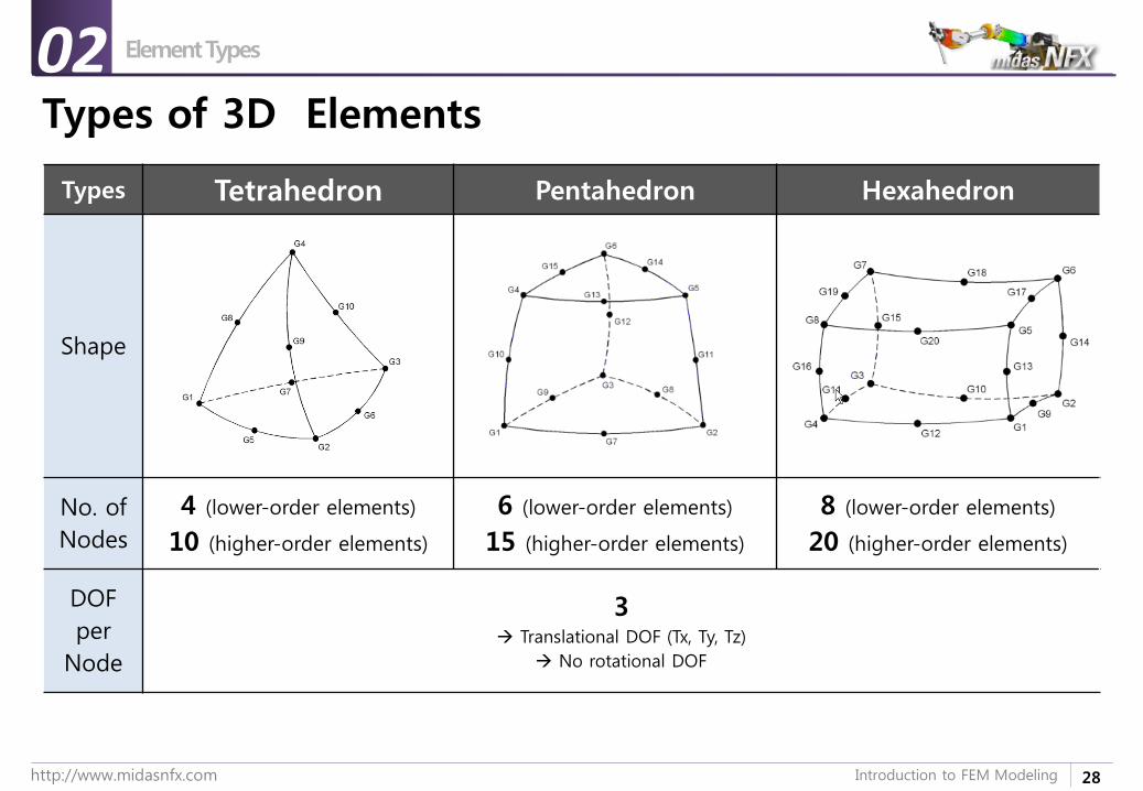
Element Types
Types of 3D Elements
Types Tetrahedron Pentahedron Hexahedron
Shape
No. of
Nodes
4 (lower-order elements)
10 (higher-order elements)
6 (lower-order elements)
15 (higher-order elements)
8 (lower-order elements)
20 (higher-order elements)
DOF
per
Node
3 Translational DOF (Tx, Ty, Tz)
No rotational DOF
02
29http://www.midasnfx.com Introduction to FEM Modeling
Element Types
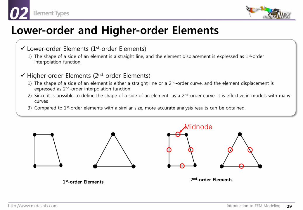
Lower-order and Higher-order Elements
Lower-order Elements (1st-order Elements)1) The shape of a side of an element is a straight line, and the element displacement is expressed as 1st-order
interpolation function
Higher-order Elements (2nd-order Elements)1) The shape of a side of an element is either a straight line or a 2nd-order curve, and the element displacement is
expressed as 2nd-order interpolation function
2) Since it is possible to define the shape of a side of an element as a 2nd-order curve, it is effective in models with many curves
3) Compared to 1st-order elements with a similar size, more accurate analysis results can be obtained.
1st-order Elements 2nd-order Elements
Midnode
02
30http://www.midasnfx.com Introduction to FEM Modeling
Element Types
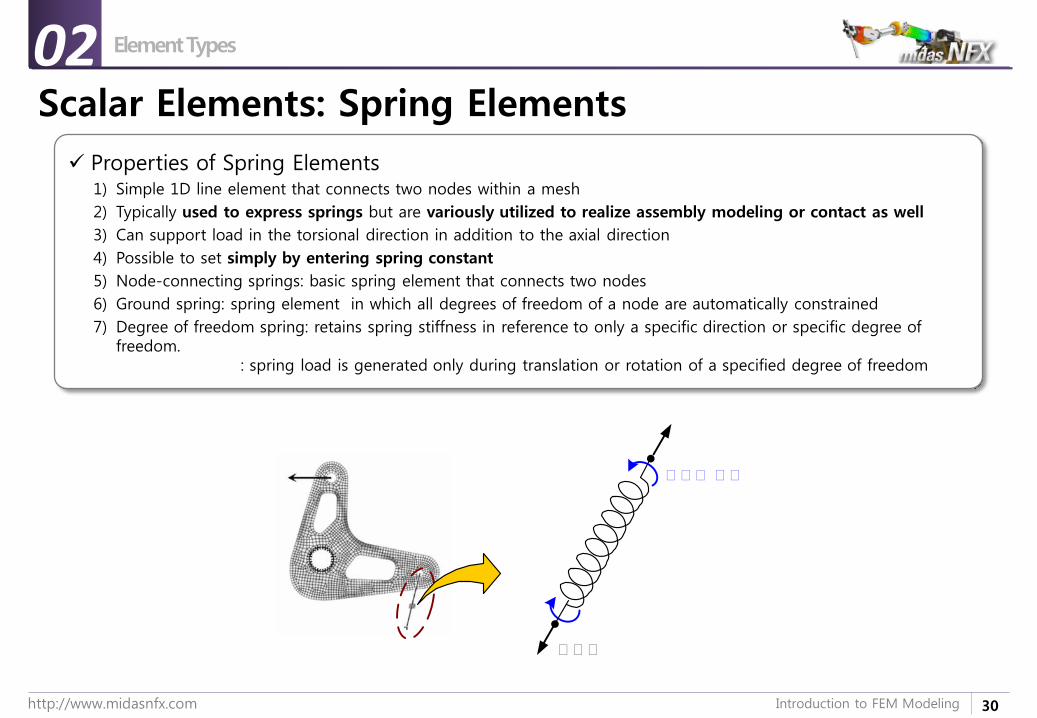
Scalar Elements: Spring Elements
Properties of Spring Elements1) Simple 1D line element that connects two nodes within a mesh
2) Typically used to express springs but are variously utilized to realize assembly modeling or contact as well
3) Can support load in the torsional direction in addition to the axial direction
4) Possible to set simply by entering spring constant
5) Node-connecting springs: basic spring element that connects two nodes
6) Ground spring: spring element in which all degrees of freedom of a node are automatically constrained
7) Degree of freedom spring: retains spring stiffness in reference to only a specific direction or specific degree of freedom.
: spring load is generated only during translation or rotation of a specified degree of freedom
축축축
축축축 축축
02
31http://www.midasnfx.com Introduction to FEM Modeling
Element Types
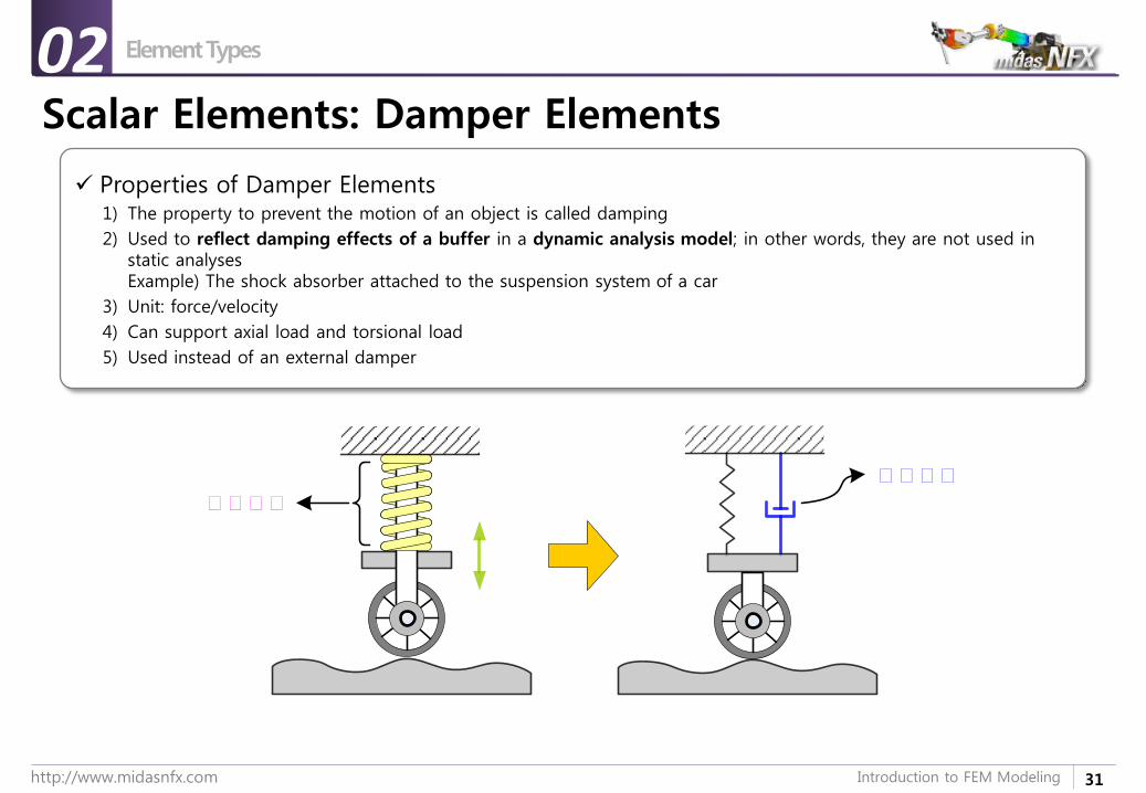
Scalar Elements: Damper Elements
Properties of Damper Elements1) The property to prevent the motion of an object is called damping
2) Used to reflect damping effects of a buffer in a dynamic analysis model; in other words, they are not used in static analysesExample) The shock absorber attached to the suspension system of a car
3) Unit: force/velocity
4) Can support axial load and torsional load
5) Used instead of an external damper
감감감감
축축축축
02
32http://www.midasnfx.com Introduction to FEM Modeling
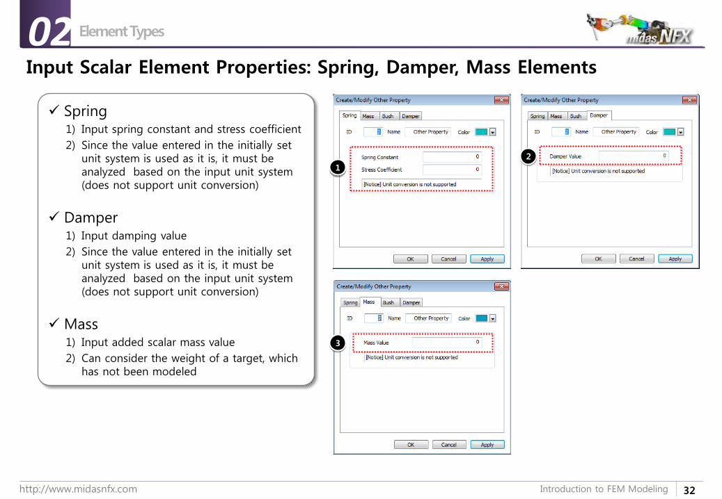
Input Scalar Element Properties: Spring, Damper, Mass Elements
Spring1) Input spring constant and stress coefficient
2) Since the value entered in the initially set unit system is used as it is, it must be analyzed based on the input unit system (does not support unit conversion)
Damper1) Input damping value
2) Since the value entered in the initially set unit system is used as it is, it must be analyzed based on the input unit system (does not support unit conversion)
Mass1) Input added scalar mass value
2) Can consider the weight of a target, which has not been modeled
1
2
3
Element Types02
33http://www.midasnfx.com Introduction to FEM Modeling
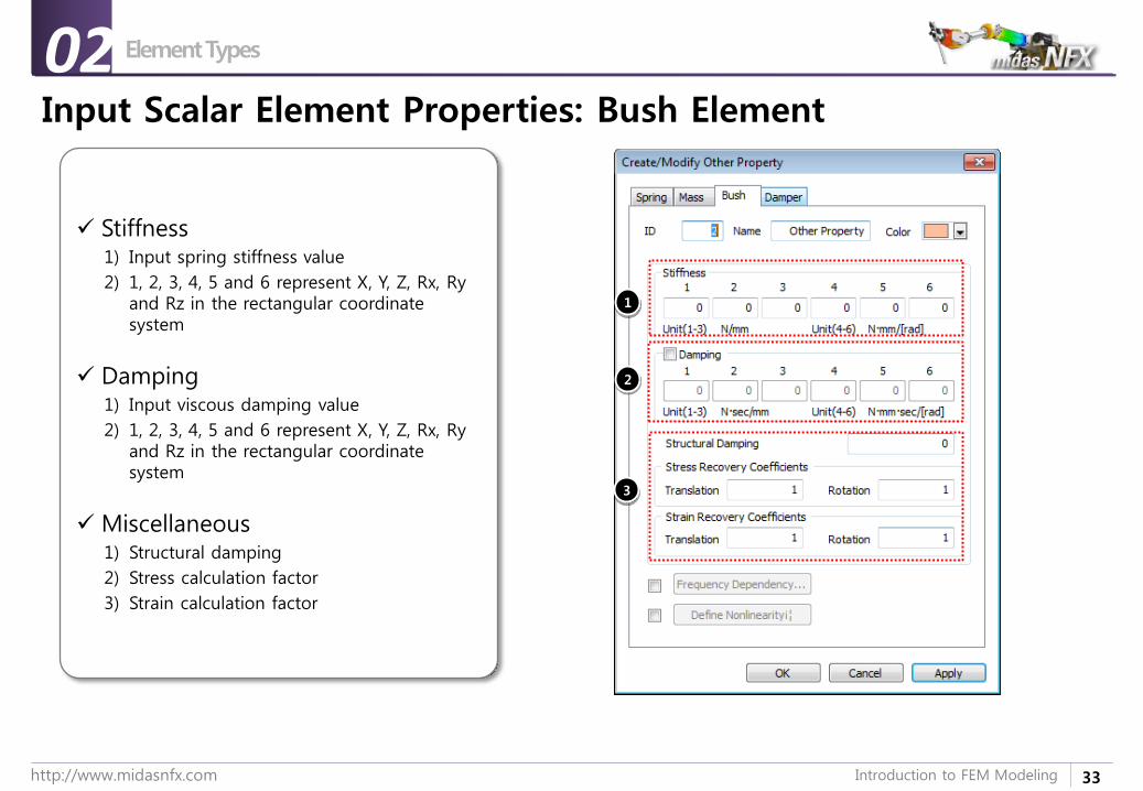
Input Scalar Element Properties: Bush Element
Stiffness1) Input spring stiffness value
2) 1, 2, 3, 4, 5 and 6 represent X, Y, Z, Rx, Ryand Rz in the rectangular coordinate system
Damping1) Input viscous damping value
2) 1, 2, 3, 4, 5 and 6 represent X, Y, Z, Rx, Ryand Rz in the rectangular coordinate system
Miscellaneous1) Structural damping
2) Stress calculation factor
3) Strain calculation factor
1
2
3
Element Types02
34http://www.midasnfx.com Introduction to FEM Modeling
Element Types
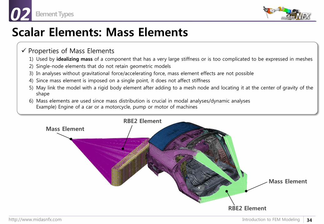
Scalar Elements: Mass Elements
Properties of Mass Elements1) Used by idealizing mass of a component that has a very large stiffness or is too complicated to be expressed in meshes
2) Single-node elements that do not retain geometric models
3) In analyses without gravitational force/accelerating force, mass element effects are not possible
4) Since mass element is imposed on a single point, it does not affect stiffness
5) May link the model with a rigid body element after adding to a mesh node and locating it at the center of gravity of the shape
6) Mass elements are used since mass distribution is crucial in modal analyses/dynamic analysesExample) Engine of a car or a motorcycle, pump or motor of machines
RBE2 Element
Mass Element
Mass Element
RBE2 Element
02
35http://www.midasnfx.com Introduction to FEM Modeling
Element Types
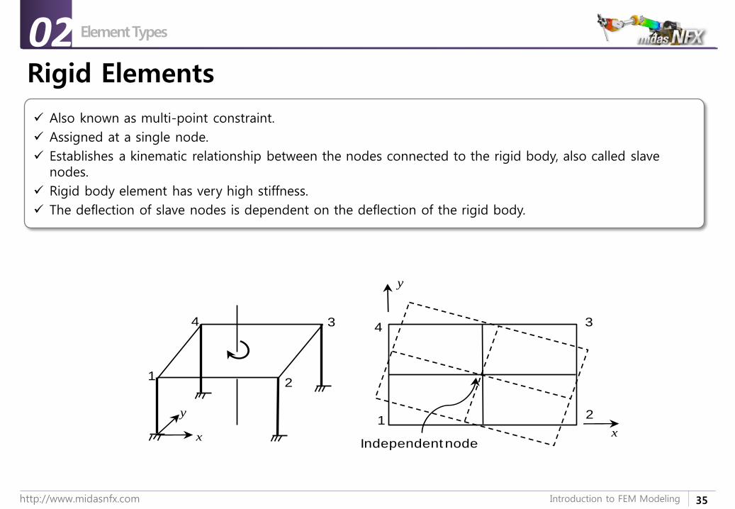
Rigid Elements
Also known as multi-point constraint.
Assigned at a single node.
Establishes a kinematic relationship between the nodes connected to the rigid body, also called slave nodes.
Rigid body element has very high stiffness.
The deflection of slave nodes is dependent on the deflection of the rigid body.
x
y
1
1
2
34
x
y
Independent node
2
34
02
36http://www.midasnfx.com Introduction to FEM Modeling
Element Types
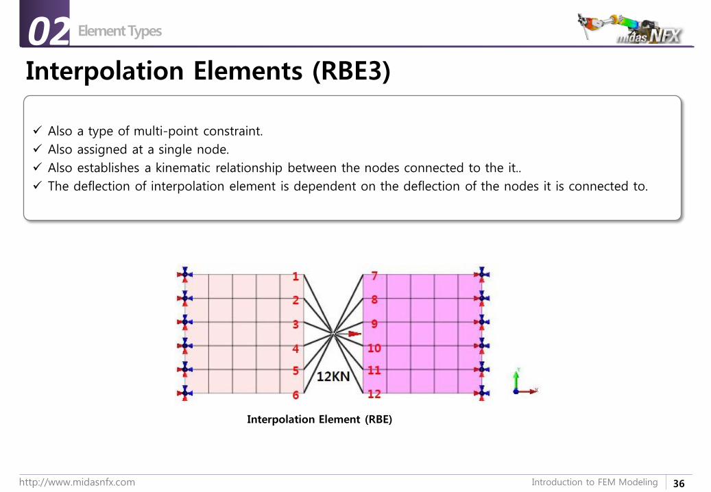
Interpolation Elements (RBE3)
Interpolation Element (RBE)
02
Also a type of multi-point constraint.
Also assigned at a single node.
Also establishes a kinematic relationship between the nodes connected to the it..
The deflection of interpolation element is dependent on the deflection of the nodes it is connected to.

37http://www.midasnfx.com Introduction to FEM Modeling
Question Time
Question Time00
What is the difference between Rigid Body & Interpolation elements?
Send in your answers to [email protected] best answers shall be featured on the next webinar (April 15)
38http://www.midasnfx.com Introduction to FEM Modeling
1. Introduction
2. Element Types
3. Sample Exercise: 1D Modeling
4. Meshing tools
5. Loads and Boundary Conditions
6. Sample Exercise 2: Bracket
Introduction to FEM Modeling
39http://www.midasnfx.com Introduction to FEM Modeling
개요
해석목적
Sample Exercise: 1D Modeling
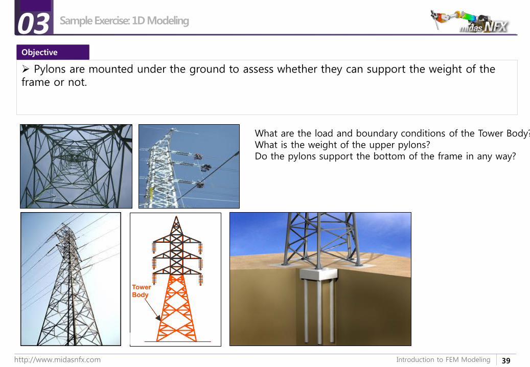
Pylons are mounted under the ground to assess whether they can support the weight of the frame or not.
What are the load and boundary conditions of the Tower Body?What is the weight of the upper pylons?Do the pylons support the bottom of the frame in any way?
03Objective
40http://www.midasnfx.com Introduction to FEM Modeling
예제 목적
실습 개요
Step개요
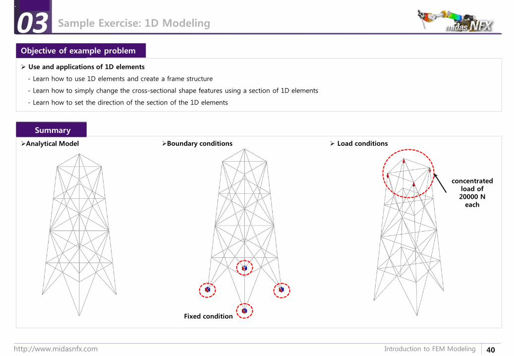
Analytical Model Boundary conditions Load conditions
concentrated load of 20000 N
each
Use and applications of 1D elements
- Learn how to use 1D elements and create a frame structure
- Learn how to simply change the cross-sectional shape features using a section of 1D elements
- Learn how to set the direction of the section of the 1D elements
03
Fixed condition
Objective of example problem
Summary
Sample Exercise: 1D Modeling
41http://www.midasnfx.com Introduction to FEM Modeling
1. Introduction
2. Element Types
3. Sample Exercise: 1D Modeling
4. Meshing tools
5. Loads and Boundary Conditions
6. Sample Exercise 2: Bracket
Introduction to FEM Modeling
42http://www.midasnfx.com Introduction to FEM Modeling
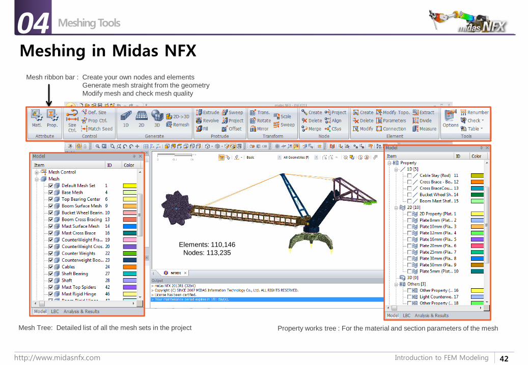
Meshing in Midas NFX
Meshing Tools04
Mesh ribbon bar : Create your own nodes and elements
Generate mesh straight from the geometry
Modify mesh and check mesh quality
Mesh Tree: Detailed list of all the mesh sets in the project Property works tree : For the material and section parameters of the mesh
Elements: 110,146
Nodes: 113,235
44http://www.midasnfx.com Introduction to FEM Modeling
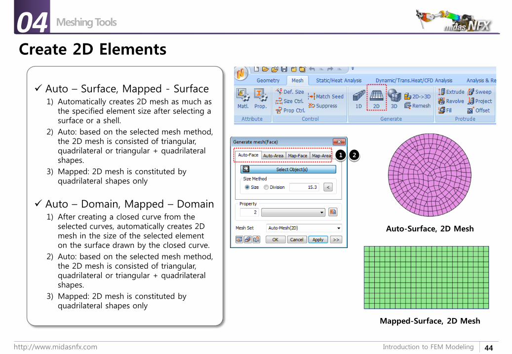
Create 2D Elements
Auto – Surface, Mapped - Surface1) Automatically creates 2D mesh as much as
the specified element size after selecting a surface or a shell.
2) Auto: based on the selected mesh method, the 2D mesh is consisted of triangular, quadrilateral or triangular + quadrilateral shapes.
3) Mapped: 2D mesh is constituted by quadrilateral shapes only
Auto – Domain, Mapped – Domain1) After creating a closed curve from the
selected curves, automatically creates 2D mesh in the size of the selected element on the surface drawn by the closed curve.
2) Auto: based on the selected mesh method, the 2D mesh is consisted of triangular, quadrilateral or triangular + quadrilateral shapes.
3) Mapped: 2D mesh is constituted by quadrilateral shapes only
1 2
Mapped-Surface, 2D Mesh
Auto-Surface, 2D Mesh
Meshing Tools04
45http://www.midasnfx.com Introduction to FEM Modeling
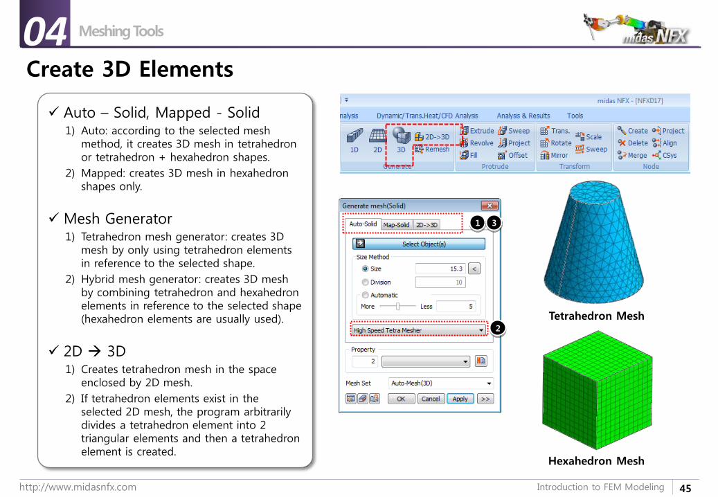
Create 3D Elements
Auto – Solid, Mapped - Solid1) Auto: according to the selected mesh
method, it creates 3D mesh in tetrahedron or tetrahedron + hexahedron shapes.
2) Mapped: creates 3D mesh in hexahedron shapes only.
Mesh Generator1) Tetrahedron mesh generator: creates 3D
mesh by only using tetrahedron elements in reference to the selected shape.
2) Hybrid mesh generator: creates 3D mesh by combining tetrahedron and hexahedron elements in reference to the selected shape (hexahedron elements are usually used).
2D 3D1) Creates tetrahedron mesh in the space
enclosed by 2D mesh.
2) If tetrahedron elements exist in the selected 2D mesh, the program arbitrarily divides a tetrahedron element into 2 triangular elements and then a tetrahedron element is created.
1
2
3
Hexahedron Mesh
Tetrahedron Mesh
Meshing Tools04
48http://www.midasnfx.com Introduction to FEM Modeling
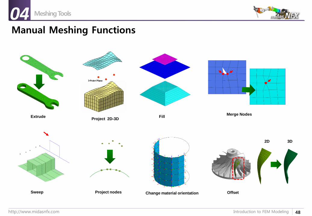
Manual Meshing Functions
Meshing Tools04
Sweep
ExtrudeProject 2D-3D
Fill
OffsetProject nodes Change material orientation
Merge Nodes
2D 3D
49http://www.midasnfx.com Introduction to FEM Modeling
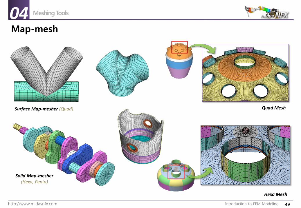
Map-mesh
Meshing Tools04
Surface Map-mesher (Quad)
Solid Map-mesher(Hexa, Penta)
Quad Mesh
Hexa Mesh
50http://www.midasnfx.com Introduction to FEM Modeling
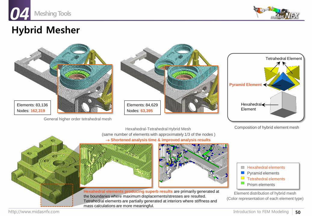
Hybrid Mesher
Meshing Tools04
Elements: 84,629
Nodes: 63,395
Elements: 83,136
Nodes: 162,319
Hexahedral elements
Pyramid elements
Tetrahedral elements
Prism elements
General higher order tetrahedral mesh
Hexahedral-Tetrahedral Hybrid Mesh
(same number of elements with approximately 1/3 of the nodes )
Shortened analysis time & improved analysis results
Element distribution of hybrid mesh
(Color representation of each element type)
Hexahedral
Element
Pyramid Element
Tetrahedral Element
Composition of hybrid element mesh
Hexahedral elements producing superb results are primarily generated at
the boundaries where maximum displacements/stresses are resulted.
Tetrahedral elements are partially generated at interiors where stiffness and
mass calculations are more meaningful.
51http://www.midasnfx.com Introduction to FEM Modeling
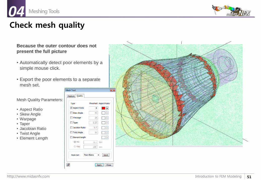
Check mesh quality
Meshing Tools04
Because the outer contour does not
present the full picture
• Automatically detect poor elements by a
simple mouse click.
• Export the poor elements to a separate
mesh set.
Mesh Quality Parameters:
• Aspect Ratio
• Skew Angle
• Warpage
• Taper
• Jacobian Ratio
• Twist Angle
• Element Length
52http://www.midasnfx.com Introduction to FEM Modeling
Opinion Time
Question for all00
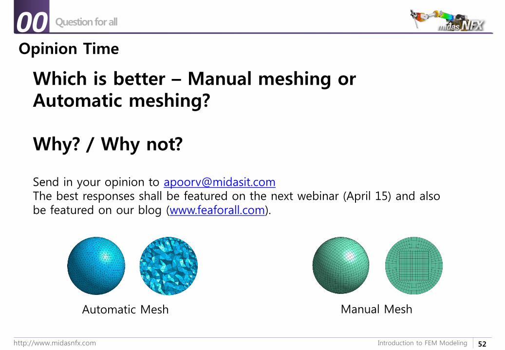
Which is better – Manual meshing or Automatic meshing?
Why? / Why not?
Send in your opinion to [email protected] best responses shall be featured on the next webinar (April 15) and also be featured on our blog (www.feaforall.com).
Automatic Mesh Manual Mesh
53http://www.midasnfx.com Introduction to FEM Modeling
1. Introduction
2. Element Types
3. Sample Exercise: 1D Modeling
4. Meshing Tools
5. Loads & Boundary Conditions
6. Sample Exercise 2: Bracket
Introduction to FEM Modeling
54http://www.midasnfx.com Introduction to FEM Modeling
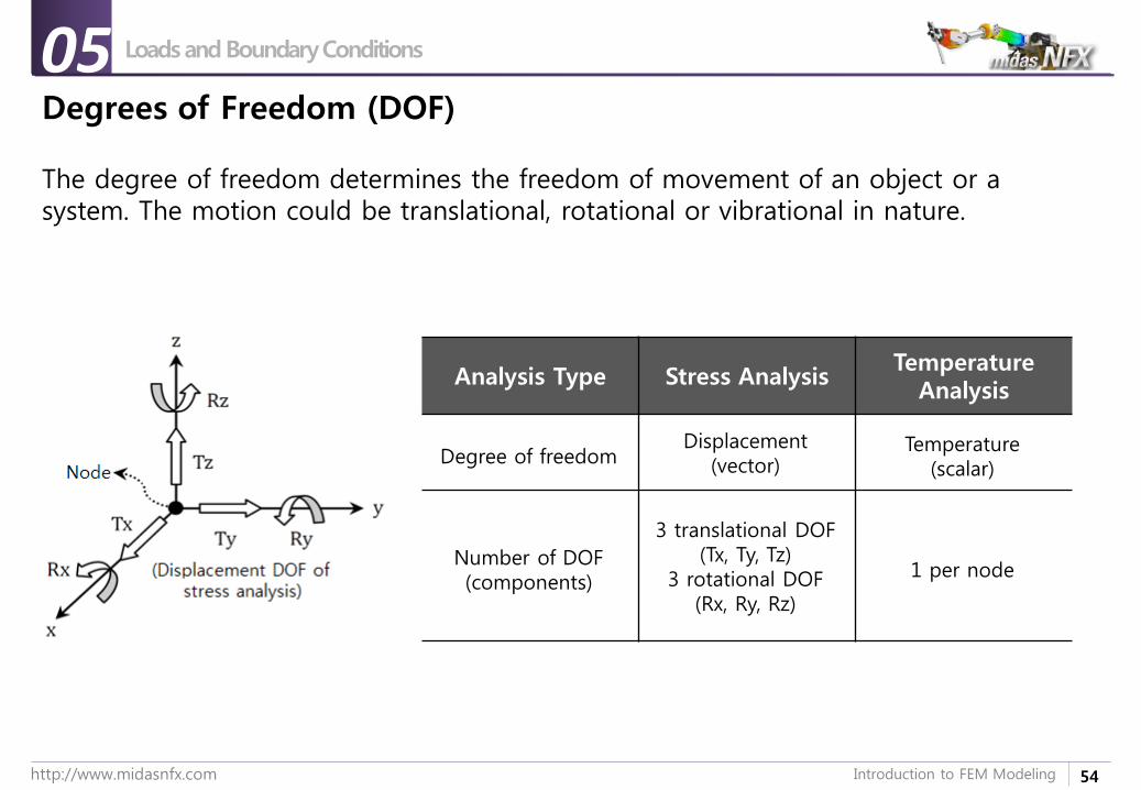
Degrees of Freedom (DOF)
Analysis Type Stress AnalysisTemperature
Analysis
Degree of freedomDisplacement
(vector)Temperature
(scalar)
Number of DOF(components)
3 translational DOF(Tx, Ty, Tz)
3 rotational DOF(Rx, Ry, Rz)
1 per node
Loads and Boundary Conditions05
The degree of freedom determines the freedom of movement of an object or a system. The motion could be translational, rotational or vibrational in nature.
55http://www.midasnfx.com Introduction to FEM Modeling
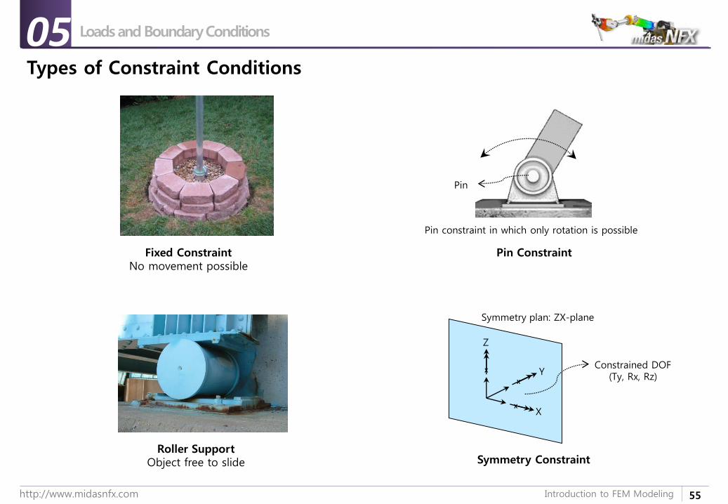
Types of Constraint Conditions
Pin Constraint
Pin constraint in which only rotation is possible
Pin
Symmetry Constraint
Symmetry plan: ZX-plane
Constrained DOF(Ty, Rx, Rz)
X
X
X
X
Y
Z
Loads and Boundary Conditions05
Roller SupportObject free to slide
Fixed ConstraintNo movement possible
56http://www.midasnfx.com Introduction to FEM Modeling
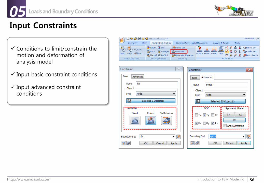
Input Constraints
Conditions to limit/constrain the motion and deformation of analysis model
Input basic constraint conditions
Input advanced constraint conditions
Loads and Boundary Conditions05
57http://www.midasnfx.com Introduction to FEM Modeling
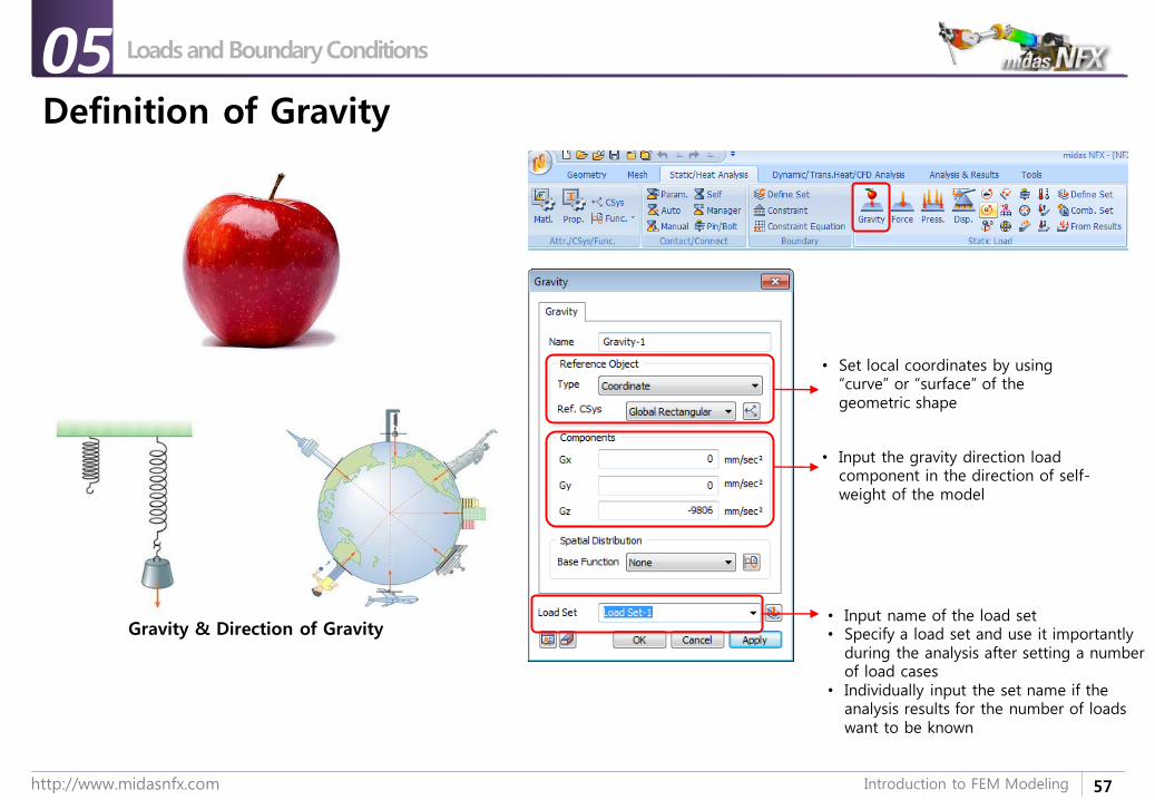
Definition of Gravity
Gravity & Direction of Gravity
• Set local coordinates by using “curve” or “surface” of the geometric shape
• Input the gravity direction load component in the direction of self-weight of the model
• Input name of the load set• Specify a load set and use it importantly
during the analysis after setting a number of load cases
• Individually input the set name if the analysis results for the number of loads want to be known
Loads and Boundary Conditions05
58http://www.midasnfx.com Introduction to FEM Modeling
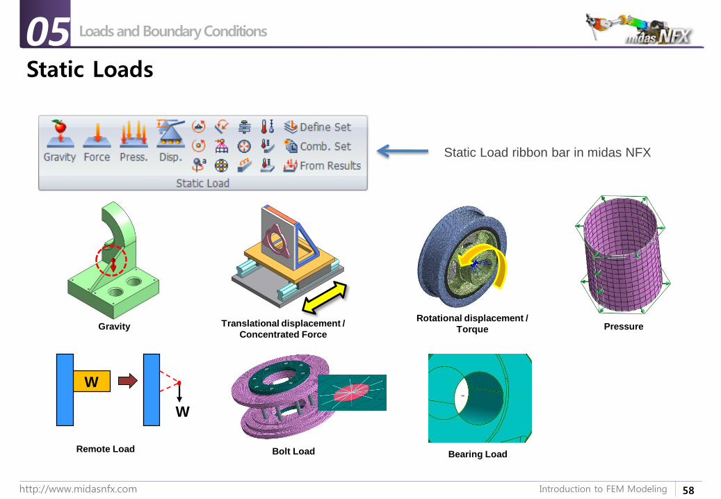
Static Loads
Loads and Boundary Conditions05
GravityRotational displacement /
TorqueTranslational displacement /
Concentrated Force
Remote Load
W
W
Bolt Load
Pressure
Static Load ribbon bar in midas NFX
Bearing Load
59http://www.midasnfx.com Introduction to FEM Modeling
1. Introduction
2. Element Types
3. Sample Exercise: 1D Modeling
4. Meshing Tools
5. Loads and Boundary Conditions
6. Sample Exercise 2: Bracket
Introduction to FEM Modeling
60http://www.midasnfx.com Introduction to FEM Modeling
예제 목적
실습 개요
Step개요
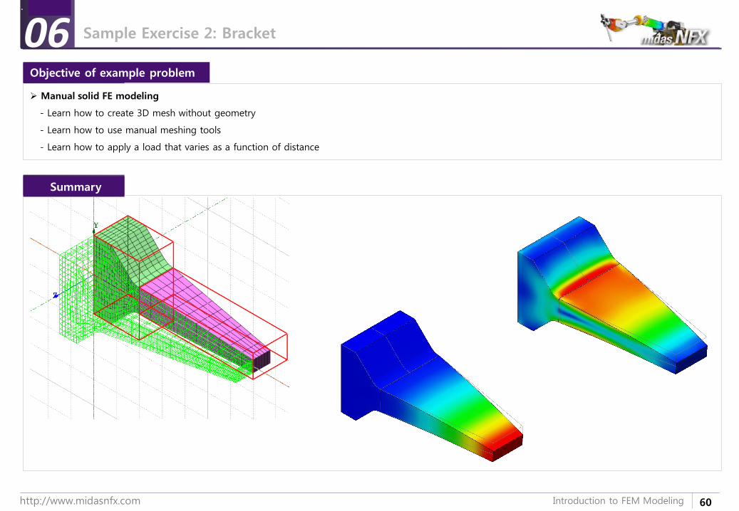
Manual solid FE modeling
- Learn how to create 3D mesh without geometry
- Learn how to use manual meshing tools
- Learn how to apply a load that varies as a function of distance
06Objective of example problem
Summary
Sample Exercise 2: Bracket
61http://www.midasnfx.com Introduction to FEM Modeling
How to get more training material ?

62http://www.midasnfx.com Introduction to FEM Modeling
How to get more learning resources
www.midasNFX.com
19

63http://www.midasnfx.com Introduction to FEM Modeling
Thank you very much for attending the webinar !
Q&AJoin us
Next Webinar (2015-04-15):
Laminar and turbulent flows using Midas NFX