Introduction Handbook on FIAT Bogie fQ,V cksxh ij fQ,V ... · Hkwfedk /Preface FIAT bogie is a...
95
(Govt. of India) (Ministry of Railways) Introduction Handbook on FIAT Bogie fQ,V cksxh ij fQ,V cksxh ij fQ,V cksxh ij fQ,V cksxh ij Ifjp; gLr iqfLrdk Ifjp; gLr iqfLrdk Ifjp; gLr iqfLrdk Ifjp; gLr iqfLrdk (For official use only) IRCAMTECH/M/12-13/FIAT Bogie/1.0 July 2012 MAHARAJPUR, GWALIOR -474005 egkjktiq j, Xokfy;j
Transcript of Introduction Handbook on FIAT Bogie fQ,V cksxh ij fQ,V ... · Hkwfedk /Preface FIAT bogie is a...
(Govt. of India) (Ministry of Railways)
Introduction Handbook on FIAT Bogie fQ,V cksxh ij fQ,V cksxh ij fQ,V cksxh ij fQ,V cksxh ij Ifjp; gLr iqfLrdkIfjp; gLr iqfLrdkIfjp; gLr iqfLrdkIfjp; gLr iqfLrdk
(For official use only) IRCAMTECH/M/12-13/FIAT Bogie/1.0
July 2012
MAHARAJPUR, GWALIOR -474005 egkjktiqj, Xokfy;j
IzkIzkIzkIzkkkkkDdFkuDdFkuDdFkuDdFku/Foreword
This hand book has covered introduction, constructional
detail of FIAT Bogie, instructions and precautions during
inspection and maintenance. Wherever required, sketches
and colored photographs have been provided to make the
understanding clear.
I am sure that the handbook will be useful to the
concerned staff to ensure trouble free service of the train
operation.
Technological up-gradation and learning is a continuous
process. Hence feel free to write us for any addition /
modifications or in case you have any suggestion to
improve the Hand Book, your contribution in this
direction shall be highly appreciated.
We welcome any suggestion for addition and improvements from our readers.
Place: CAMTECH/GWL (A R Tupe ) Date: 30/06/2012 Exe. Director
HkwfedkHkwfedkHkwfedkHkwfedk /Preface
FIAT bogie is a vital part of the LHB coaches. These
type of coaches have already been introduced on Indian
Railway having better riding index and higher reliability.
Knowledge of proper maintenance of FIAT bogie is
necessary to ensure higher reliabity and timely availabity
of coaches in workshop as well as on line.
The purpose of this hand book is to enhance knowledge
and competence of C&W staff in dealing with LHB
coach maintenance.
It is clarified that this handbook does not supersede any
existing procedures and practices laid down in the
maintenance instructions issued by manufacturers or by
RDSO/LKO.
30th June 2012 (K.P.Yadav) CAMTECH GWALIOR Director/Mech
CORRECTION SLIPS
The correction slips to be issued in future for this handbook will be numbered as follows: CAMTECH//M/12-13/FIAT Bogie/1.0/C.S. # XX date ……………. Where “XX” is the serial number of the concerned correction slip (Starting from 01 onwards) CORRECTION SLIPS ISSUED
Sr.No. of
C.Slip Date of issue
Page No. and Item no. modified
Remarks

la’kks/ku la’kks/ku la’kks/ku la’kks/ku iphZiphZiphZiphZ
bl iqfLrdk ds fy;s Hkfo"; esa izdkf’kr gksus okyh la’kks/ku ifpZ;k s dks fuEukuqlkj la[;kafdr fd;k tk,xk :
dSeVsd@;k¡@12&13@ fQ,V cksxh@1-0@xx fnukad ........
tgkW “ xx ” lEcfU/kr la’kks/ku iphZ dh Øze la[;k gS ¼ 01 ls izkjEHk gksdj vkxs dh vksj ½A
izdkf’kr la’kks/ku ifpZ;kWaizdkf’kr la’kks/ku ifpZ;kWaizdkf’kr la’kks/ku ifpZ;kWaizdkf’kr la’kks/ku ifpZ;kWa
la’kks/ku iphZ la’kks/ku iphZ la’kks/ku iphZ la’kks/ku iphZ dh la[;kdh la[;kdh la[;kdh la[;k
izdk’ku dh izdk’ku dh izdk’ku dh izdk’ku dh rkjh[krkjh[krkjh[krkjh[k
la’kksf/kr Ik̀"B la[;k la’kksf/kr Ik̀"B la[;k la’kksf/kr Ik̀"B la[;k la’kksf/kr Ik̀"B la[;k ,oa en la[;k,oa en la[;k,oa en la[;k,oa en la[;k
fVIi.khfVIi.khfVIi.khfVIi.kh
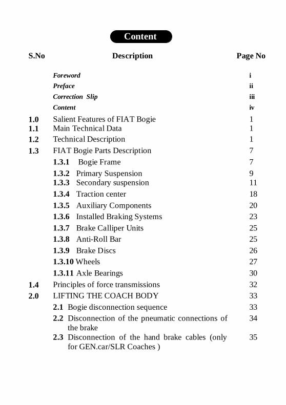
Contents
S.No Description Page No
Foreword i
Preface ii
Correction Slip iii
Content iv
1.0 Salient Features of FIAT Bogie 1 1.1 Main Technical Data 1 1.2 Technical Description 1
1.3 FIAT Bogie Parts Description 7
1.3.1 Bogie Frame 7
1.3.2 Primary Suspension 9 1.3.3 Secondary suspension 11
1.3.4 Traction center 18
1.3.5 Auxiliary Components 20 1.3.6 Installed Braking Systems 23
1.3.7 Brake Calliper Units 25 1.3.8 Anti-Roll Bar 25
1.3.9 Brake Discs 26 1.3.10 Wheels 27
1.3.11 Axle Bearings 30
1.4 Principles of force transmissions 32
2.0 LIFTING THE COACH BODY 33
2.1 Bogie disconnection sequence 33
2.2 Disconnection of the pneumatic connections of the brake
34
2.3 Disconnection of the hand brake cables (only for GEN.car/SLR Coaches )
35
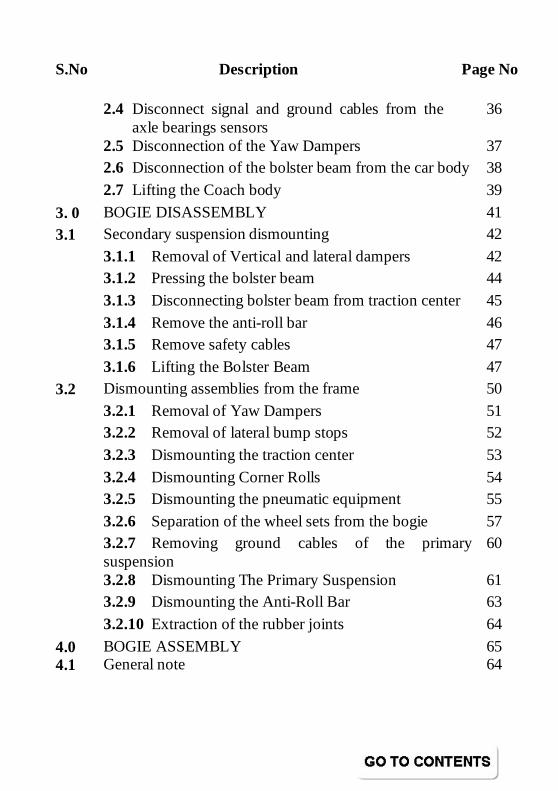
S.No Description Page No
2.4 Disconnect signal and ground cables from the axle bearings sensors
36
2.5 Disconnection of the Yaw Dampers 37
2.6 Disconnection of the bolster beam from the car body 38
2.7 Lifting the Coach body 39
3. 0 BOGIE DISASSEMBLY 41
3.1 Secondary suspension dismounting 42
3.1.1 Removal of Vertical and lateral dampers 42
3.1.2 Pressing the bolster beam 44
3.1.3 Disconnecting bolster beam from traction center 45
3.1.4 Remove the anti-roll bar 46
3.1.5 Remove safety cables 47
3.1.6 Lifting the Bolster Beam 47
3.2 Dismounting assemblies from the frame 50
3.2.1 Removal of Yaw Dampers 51 3.2.2 Removal of lateral bump stops 52
3.2.3 Dismounting the traction center 53
3.2.4 Dismounting Corner Rolls 54
3.2.5 Dismounting the pneumatic equipment 55
3.2.6 Separation of the wheel sets from the bogie 57
3.2.7 Removing ground cables of the primary suspension
60
3.2.8 Dismounting The Primary Suspension 61
3.2.9 Dismounting the Anti-Roll Bar 63
3.2.10 Extraction of the rubber joints 64
4.0 BOGIE ASSEMBLY 65 4.1 General note 64
S.No Description Page No
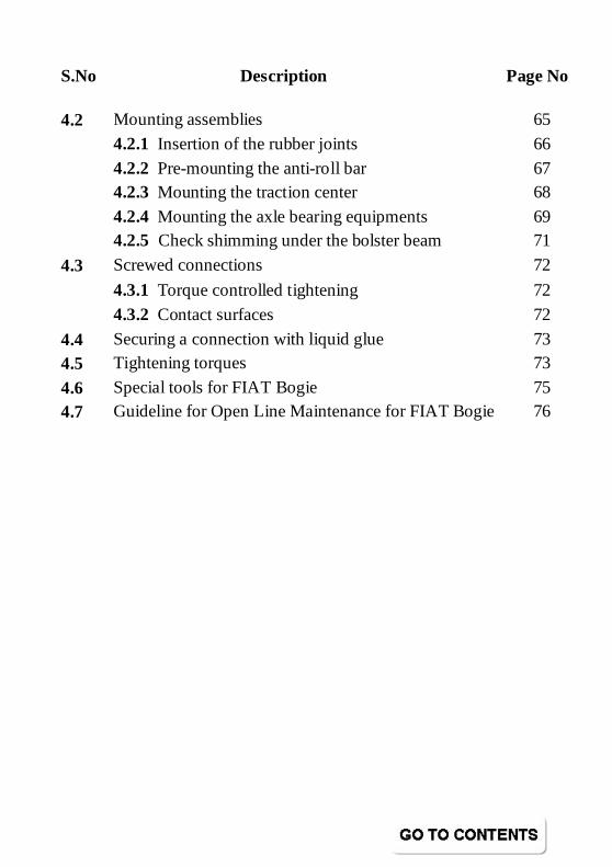
4.2 Mounting assemblies 65
4.2.1 Insertion of the rubber joints 66
4.2.2 Pre-mounting the anti-roll bar 67
4.2.3 Mounting the traction center 68
4.2.4 Mounting the axle bearing equipments 69
4.2.5 Check shimming under the bolster beam 71
4.3 Screwed connections 72
4.3.1 Torque controlled tightening 72
4.3.2 Contact surfaces 72
4.4 Securing a connection with liquid glue 73
4.5 Tightening torques 73
4.6 Special tools for FIAT Bogie 75
4.7 Guideline for Open Line Maintenance for FIAT Bogie 76
fc"k; lwph fc"k; lwph fc"k; lwph fc"k; lwph Conten
ØØØØ.lalalala---- fc"k; lwph fc"k; lwph fc"k; lwph fc"k; lwph i`"B la[;ki`"B la[;ki`"B la[;ki`"B la[;k
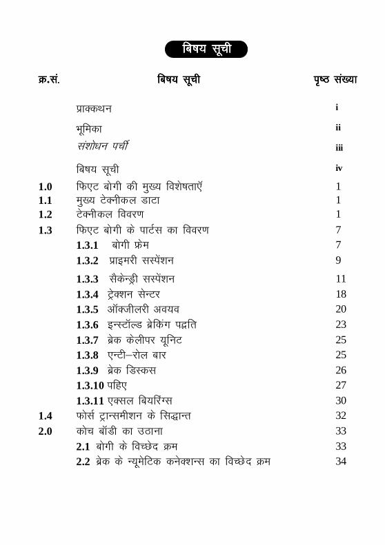
izkDdFku i
Hkwfedk ii
la’kks/ku iphZ iii
fc"k; lwph iv
1.0 fQ,V cksxh dh eq[; fo'ks"krk,W 1 1.1 eq[; VsDuhdy MkVk 1 1.2 VsDuhdy fooj.k 1
1.3 fQ,V cksxh ds ikVZl dk fooj.k 7 1.3.1 cksxh Ýse 7
1.3.2 izkbejh lLisa’ku 9
1.3.3 lSdsUMªh lLisa’ku 11
1.3.4 VªsD’ku lsUVj 18 1.3.5 vkWDthyjh vo;o 20
1.3.6 bULVkWYM czsfdax iöfr 23
1.3.7 czsd dsyhij ;wfuV 25 1.3.8 ,UVh&jksy ckj 25
1.3.9 czsd fMLdl 26 1.3.10 ifg, 27
1.3.11 ,Dly fc;fjaXl 30
1.4 QkslZ VªkUleh’ku ds fl)kUr 32
2.0 dksp ckWMh dk mBkuk 33
2.1 cksxh ds foPNsn Øe 33
2.2 czsd ds U;wesfVd dusD’kUl dk foPNsn Øe 34
ØØØØ.lalalala---- fc"k; lwph fc"k; lwph fc"k; lwph fc"k; lwph i`"B la[;ki`"B la[;ki`"B la[;ki`"B la[;k
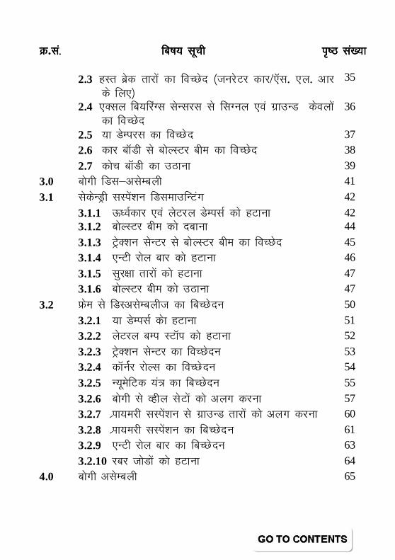
2.3 gLr czsd rkjksa dk foPNsn ¼tujsVj dkj/,Wl. ,y. vkj ds fy,½
35
2.4 ,Dly fc;fjaXl lsUljl ls flXuy ,oa xzkmUM dsoyksa dk foPNsn
36
2.5 ;k MsEijl dk foPNsn 37
2.6 dkj ckWMh ls cksYLVj che dk foPNsn 38
2.7 dksp ckWMh dk mBkuk 39
3.0 Ckksxh fMl&vlsEcyh 41
3.1 lsdsUMªh lLias’ku fMlekmfUVax 42
3.1.1 ÅËoZdkj ,oa ysVjy MsEilZ dks gVkuk 42 3.1.2 cksYLVj che dks nckuk 44
3.1.3 VªsD’ku lsUVj ls cksYLVj che dk foPNsn 45
3.1.4 ,UVh jksy ckj dks gVkuk 46
3.1.5 lqj{kk rkjksa dks gVkuk 47
3.1.6 cksYLVj che dks mBkuk 47
3.2 Ýse ls fMLvlsEcyht dk fcPNsnu 50
3.2.1 ;k MsEilZ dsk gVkuk 51 3.2.2 ysVjy cEi LVkWi dks gVkuk 52
3.2.3 VªsD’ku lsUVj dk foPNsnu 53 3.2.4 dkWuZZj jksYl dk foPNsnu 54
3.2.5 U;wesfVd ;a= dk fcPNsnu 55
3.2.6 cksxh ls Oghy lsVksa dks vyx djuk 57
3.2.7 Izkk;ejh lLisa’ku ls xzkmUM rkjksa dks vyx djuk 60
3.2.8 Izkk;ejh lLisa’ku dk fcPNsnu 61
3.2.9 ,UVh jksy ckj dk fcPNsnu 63
3.2.10 jcj tksMksa dks gVkuk 64
4.0 cksxh vlsEcyh 65
ØØØØ.lalalala---- fc"k; lwph fc"k; lwph fc"k; lwph fc"k; lwph i`"B la[;ki`"B la[;ki`"B la[;ki`"B la[;k
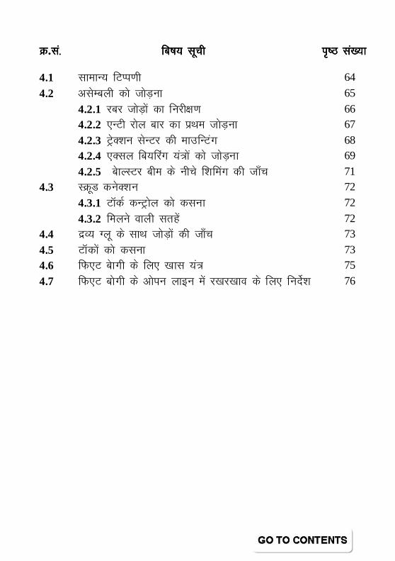
4.1 lkekU; fVIi.kh 64
4.2 vlsEcyh dks tksM+uk 65
4.2.1 jcj tksM+ksa dk fujh{k.k 66
4.2.2 ,UVh jksy ckj dk izFke tksM+uk 67
4.2.3 VªsD’ku lsUVj dh ekmfUVax 68
4.2.4 ,Dly fc;fjax ;a=ks a dks tksM+uk 69
4.2.5 cskYLVj che ds uhps f’kfeax dh tk¡p 71
4.3 LØwM dusD’ku 72
4.3.1 VkWdZ dUVªksy dks dluk 72
4.3.2 feyus okyh lrgsa 72
4.4 nzO; Xyw ds lkFk tksM+ksa dh tk¡p 73
4.5 VkWdksa dks dluk 73
4.6 fQ,V cskxh ds fy, [kkl ;a= 75
4.7 fQ,V cksxh ds vksiu ykbu esa j[kj[kko ds fy, funsZ'k 76
Introduction Handbook
on FIAT Bogie

fQ,V cksxh ij fQ,V cksxh ij fQ,V cksxh ij fQ,V cksxh ij Ifjp;Ifjp;Ifjp;Ifjp;
gLr iqfLrdkgLr iqfLrdkgLr iqfLrdkgLr iqfLrdk
No.IRCAMTECH/M/12-13/FIAT BOGIE /1.0
Introduction handbook of FIAT Bogie 1
fQ,V cksxhfQ,V cksxhfQ,V cksxhfQ,V cksxh /FIAT BOGIE 1.0 fQ,V cksxh dh eq[; fo'ks"krk,fQ,V cksxh dh eq[; fo'ks"krk,fQ,V cksxh dh eq[; fo'ks"krk,fQ,V cksxh dh eq[; fo'ks"krk, /Salient Features of Fiat
Bogie � The FIAT Bogie is an adoption of EUROFIMA
design.
� Bogie frame is a Y frame fabricated and machined structure.
� Four nested springs for primary suspension and two-nested flexi-coil springs for secondary suspension.
� Axle mounted disc brake system.
� Hydraulic shock absorbers used conforming to UIC stipulation.
Each FIAT Bogie is provided with four primary vertical, two secondary vertical, one secondary lateral and two yaw dampers
1.1 eq[; VsDuhdy MkVkeq[; VsDuhdy MkVkeq[; VsDuhdy MkVkeq[; VsDuhdy MkVk /Main Technical Data
Axle distance 2560 mm Diameter of new wheels 915 mm
Diameter of max. worn wheel 845 mm
Distance between the wheels 1600 mm
Brake disc diameter 640 mm
Bogie width 3030 mm
Bogie length 3534 mm
Bogie weight 6300 Kg
1.2 VsDuhdy fooj.kVsDuhdy fooj.kVsDuhdy fooj.kVsDuhdy fooj.k /Technical Description
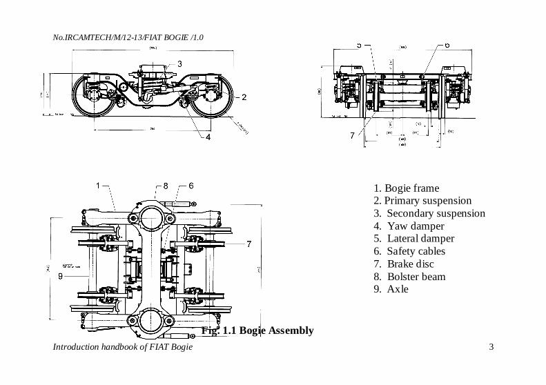
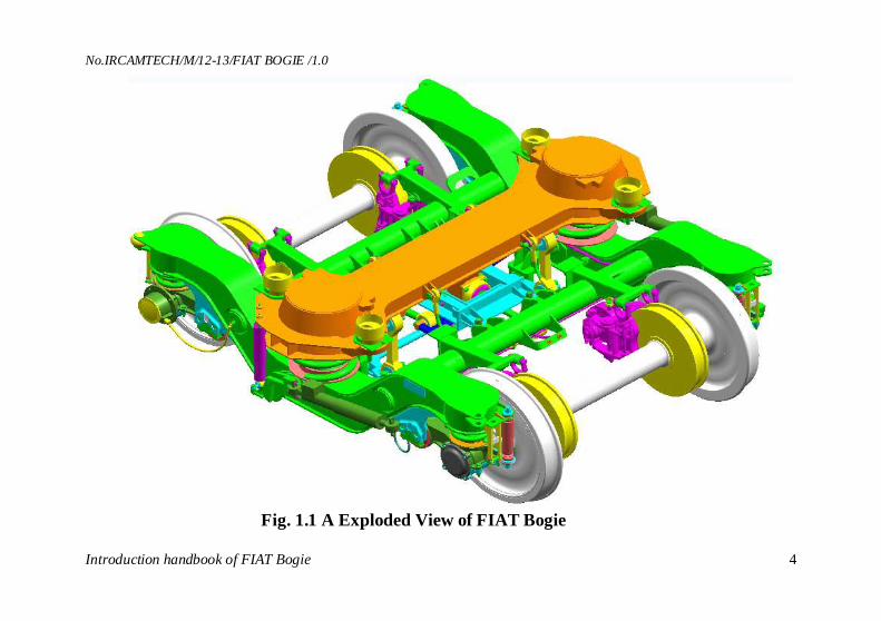
The FIAT Bogie is two-axle type, with a primary and a secondary suspension. The bogie assembly is shown in
No.IRCAMTECH/M/12-13/FIAT BOGIE /1.0
Introduction handbook of FIAT Bogie 2
fig. 1-1 & 1.1 A. Main Technical features of FIAT Bogie are:
• Solid welded Bogie Frame made up of two longitudinal components connected by two cross beams. The bogie frame rests on the primary suspension spring units and supports the vehicle body by means of Bolster beam. The Bolster beam is connected to the bogie frame by secondary suspension.
• Primary suspension consist of two steel coil springs (internal/external) laid out on the Control Arm upper part.
• Secondary suspension consists of two spring packs which sustain the bolster beam over the bogie frame. Each spring pack is made up by an internal and external spring. An Anti roll bar fitted on the bogie frame realizes a constant, reduced inclination coefficient during running. The bogie frame is linked to the bolster beam through two vertical dampers, a lateral damper, four safety cables and the traction rods. The bogie frame is linked to the coach body through two yaw dampers.
• Traction Centre - The traction Centre transmits traction and braking forces between bogie frame and body by a traction lever on the bolster beam pin and two rods.
• Disk Brakes – The FIAT bogie is fitted with pneumatic disk brakes. The pneumatically operated brake cylinders are fitted with automatic device for taking up the clearances.
• Taper Roller Cartridge Bearing – Fiat Bogie is fitted with 130 mm Cartridge type roller bearings.
No.IRCAMTECH/M/12-13/FIAT BOGIE /1.0
Introduction handbook of FIAT Bogie 3
Fig. 1.1 Bogie Assembly
1. Bogie frame 2. Primary suspension 3. Secondary suspension 4. Yaw damper 5. Lateral damper 6. Safety cables 7. Brake disc 8. Bolster beam 9. Axle
No.IRCAMTECH/M/12-13/FIAT BOGIE /1.0
Introduction handbook of FIAT Bogie 4
Fig. 1.1 A Exploded View of FIAT Bogie
No.IRCAMTECH/M/12-13/FIAT BOGIE /1.0
Introduction handbook of FIAT Bogie 5
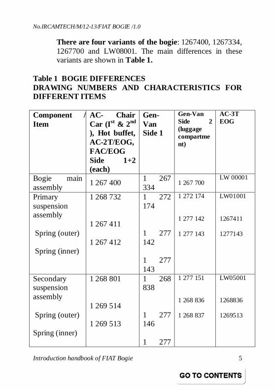
There are four variants of the bogie: 1267400, 1267334, 1267700 and LW08001. The main differences in these variants are shown in Table 1.
Table 1 BOGIE DIFFERENCES DRAWING NUMBERS AND CHARACTERISTICS FOR DIFFERENT ITEMS Component / Item
AC- Chair Car (I st & 2nd ), Hot buffet, AC-2T/EOG, FAC/EOG Side 1+2 (each)
Gen-Van Side 1
Gen-Van Side 2 (luggage compartment)
AC-3T EOG
Bogie main assembly
1 267 400 1 267 334
1 267 700 LW 00001
Primary suspension assembly Spring (outer) Spring (inner)
1 268 732 1 267 411 1 267 412
1 272 174 1 277 142 1 277 143
1 272 174 1 277 142 1 277 143
LW01001 1267411 1277143
Secondary suspension assembly Spring (outer) Spring (inner)
1 268 801 1 269 514 1 269 513
1 268 838 1 277 146 1 277
1 277 151 1 268 836 1 268 837
LW05001 1268836 1269513
No.IRCAMTECH/M/12-13/FIAT BOGIE /1.0
Introduction handbook of FIAT Bogie 6
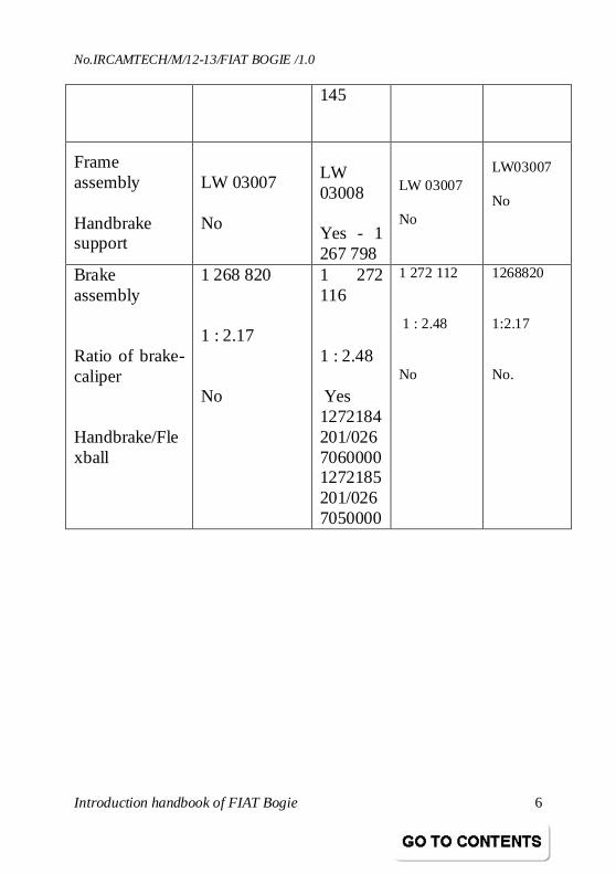
145
Frame assembly Handbrake support
LW 03007 No
LW 03008 Yes - 1 267 798
LW 03007 No
LW03007 No
Brake assembly Ratio of brake-caliper Handbrake/Flexball
1 268 820 1 : 2.17 No
1 272 116 1 : 2.48 Yes 1272184201/0267060000 1272185201/0267050000
1 272 112 1 : 2.48 No
1268820 1:2.17 No.
No.IRCAMTECH/M/12-13/FIAT BOGIE /1.0
Introduction handbook of FIAT Bogie 7
1.3 fQ,V cksxh ds ikVZl dk fooj.kfQ,V cksxh ds ikVZl dk fooj.kfQ,V cksxh ds ikVZl dk fooj.kfQ,V cksxh ds ikVZl dk fooj.k /FIAT Bogie Parts Description
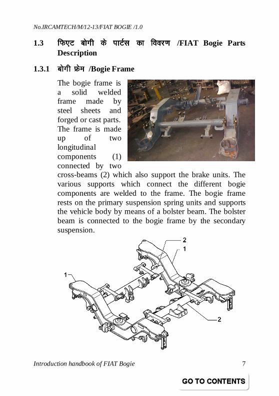
1.3.1 cksxh Ýsecksxh Ýsecksxh Ýsecksxh Ýse /Bogie Frame
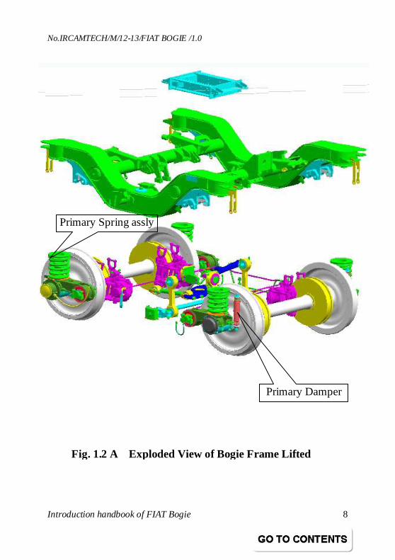
The bogie frame is a solid welded frame made by steel sheets and forged or cast parts. The frame is made up of two longitudinal components (1) connected by two cross-beams (2) which also support the brake units. The various supports which connect the different bogie components are welded to the frame. The bogie frame rests on the primary suspension spring units and supports the vehicle body by means of a bolster beam. The bolster beam is connected to the bogie frame by the secondary suspension.
No.IRCAMTECH/M/12-13/FIAT BOGIE /1.0
Introduction handbook of FIAT Bogie 8
Primary Spring assly
Primary Damper
Fig. 1.2 A Exploded View of Bogie Frame Lifted
No.IRCAMTECH/M/12-13/FIAT BOGIE /1.0
Introduction handbook of FIAT Bogie 9
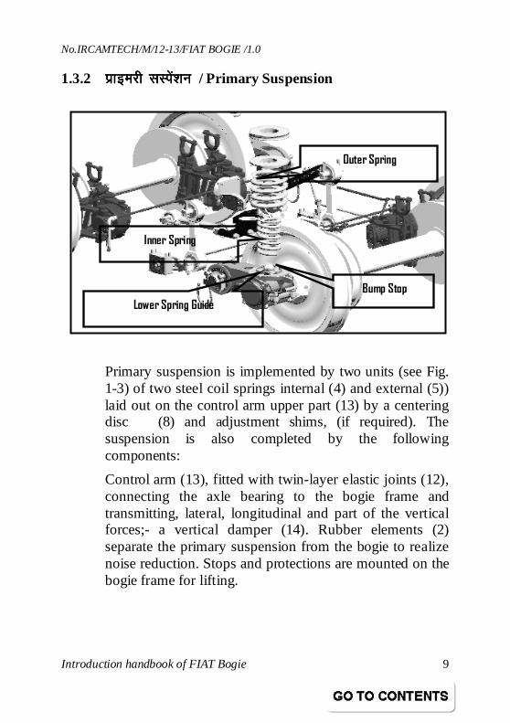
1.3.2 izkbejh lLisa’kuizkbejh lLisa’kuizkbejh lLisa’kuizkbejh lLisa’ku / Primary Suspension
Primary suspension is implemented by two units (see Fig. 1-3) of two steel coil springs internal (4) and external (5)) laid out on the control arm upper part (13) by a centering disc (8) and adjustment shims, (if required). The suspension is also completed by the following components:
Control arm (13), fitted with twin-layer elastic joints (12), connecting the axle bearing to the bogie frame and transmitting, lateral, longitudinal and part of the vertical forces;- a vertical damper (14). Rubber elements (2) separate the primary suspension from the bogie to realize noise reduction. Stops and protections are mounted on the bogie frame for lifting.
Outer Spring
Inner Spring
Bump Stop
Lower Spring Guide
No.IRCAMTECH/M/12-13/FIAT BOGIE /1.0
Introduction handbook of FIAT Bogie 10
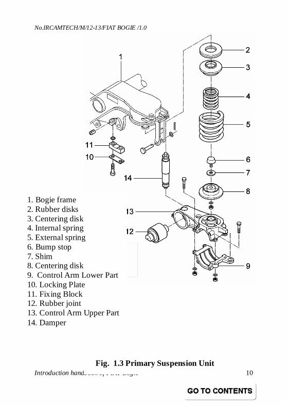
1. Bogie frame 2. Rubber disks 3. Centering disk 4. Internal spring 5. External spring 6. Bump stop 7. Shim 8. Centering disk 9. Control Arm Lower Part 10. Locking Plate 11. Fixing Block 12. Rubber joint 13. Control Arm Upper Part 14. Damper
Fig. 1.3 Primary Suspension Unit
No.IRCAMTECH/M/12-13/FIAT BOGIE /1.0
Introduction handbook of FIAT Bogie 11
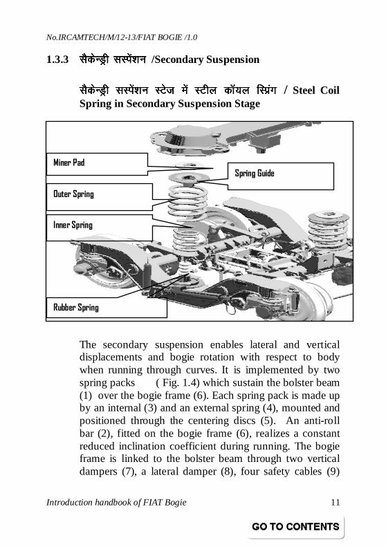
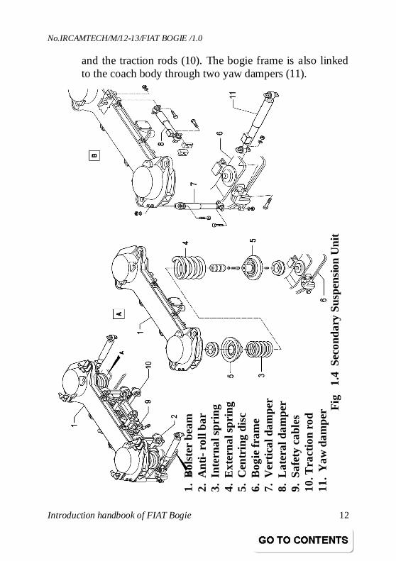
1.3.3 lSdsUMªh lLisa’kulSdsUMªh lLisa’kulSdsUMªh lLisa’kulSdsUMªh lLisa’ku /Secondary Suspension
lSdsUMªh lLisa’kulSdsUMªh lLisa’kulSdsUMªh lLisa’kulSdsUMªh lLisa’ku LVstLVstLVstLVst esa LVhy dkW;y fLizaxesa LVhy dkW;y fLizaxesa LVhy dkW;y fLizaxesa LVhy dkW;y fLizax / Steel Coil Spring in Secondary Suspension Stage
The secondary suspension enables lateral and vertical displacements and bogie rotation with respect to body when running through curves. It is implemented by two spring packs ( Fig. 1.4) which sustain the bolster beam (1) over the bogie frame (6). Each spring pack is made up by an internal (3) and an external spring (4), mounted and positioned through the centering discs (5). An anti-roll bar (2), fitted on the bogie frame (6), realizes a constant reduced inclination coefficient during running. The bogie frame is linked to the bolster beam through two vertical dampers (7), a lateral damper (8), four safety cables (9)
Miner Pad Spring Guide
Outer Spring
Inner Spring
Rubber Spring
No.IRCAMTECH/M/12-13/FIAT BOGIE /1.0
Introduction handbook of FIAT Bogie 12
and the traction rods (10). The bogie frame is also linked to the coach body through two yaw dampers (11).
1. B
olst
er b
eam
2.
Ant
i- ro
ll ba
r 3.
Int
erna
l spr
ing
4. E
xter
nal s
prin
g 5.
Cen
trin
g di
sc
6. B
ogie
fram
e 7.
Ver
tical
dam
per
8. L
ater
al d
ampe
r 9.
Saf
ety
cabl
es
10. T
ract
ion
rod
11.
Yaw
dam
per
Fig
1.
4 S
econ
dary
Sus
pens
ion
Uni
t
No.IRCAMTECH/M/12-13/FIAT BOGIE /1.0
Introduction handbook of FIAT Bogie 13
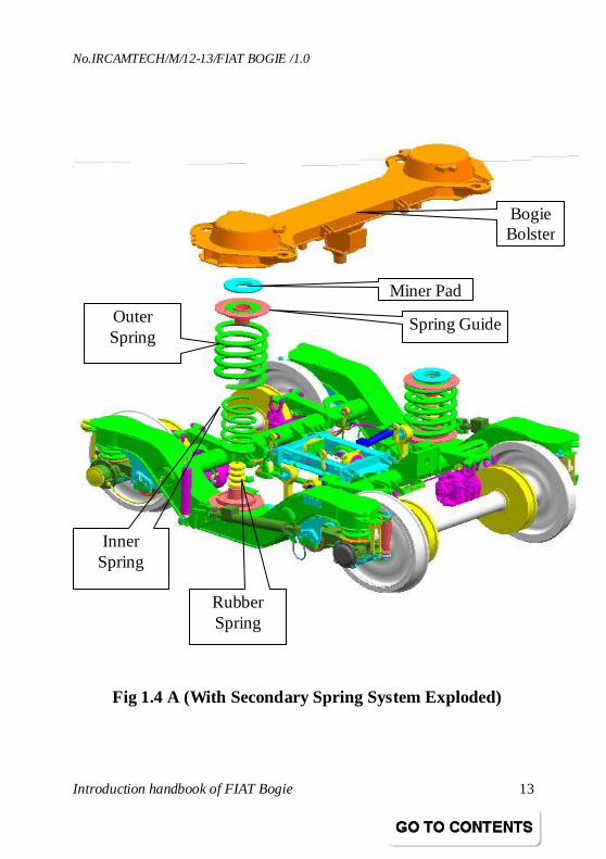
Outer Spring
Inner Spring
Spring Guide
Rubber Spring
Miner Pad
Bogie Bolster
Fig 1.4 A (With Secondary Spring System Exploded)
No.IRCAMTECH/M/12-13/FIAT BOGIE /1.0
Introduction handbook of FIAT Bogie 14
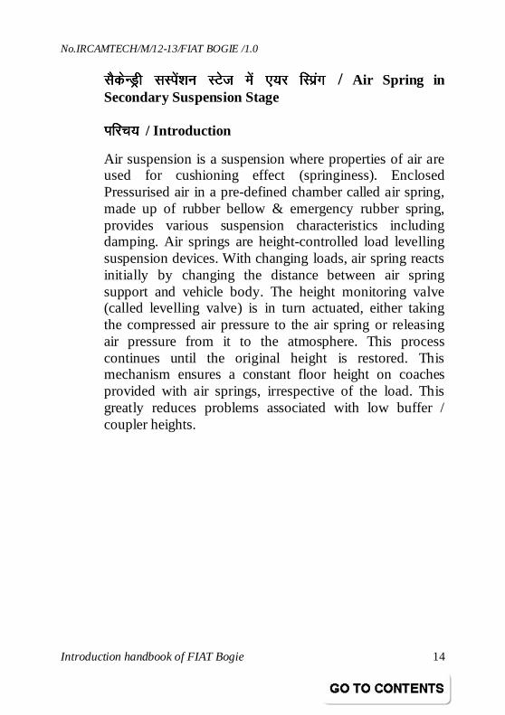
lSdsUMªh lLias’ku LVst esa ,;j fLizaxlSdsUMªh lLias’ku LVst esa ,;j fLizaxlSdsUMªh lLias’ku LVst esa ,;j fLizaxlSdsUMªh lLias’ku LVst esa ,;j fLizax / Air Spring in Secondary Suspension Stage
IIIIkkkkfjp; fjp; fjp; fjp; / Introduction
Air suspension is a suspension where properties of air are used for cushioning effect (springiness). Enclosed Pressurised air in a pre-defined chamber called air spring, made up of rubber bellow & emergency rubber spring, provides various suspension characteristics including damping. Air springs are height-controlled load levelling suspension devices. With changing loads, air spring reacts initially by changing the distance between air spring support and vehicle body. The height monitoring valve (called levelling valve) is in turn actuated, either taking the compressed air pressure to the air spring or releasing air pressure from it to the atmosphere. This process continues until the original height is restored. This mechanism ensures a constant floor height on coaches provided with air springs, irrespective of the load. This greatly reduces problems associated with low buffer / coupler heights.
No.IRCAMTECH/M/12-13/FIAT BOGIE /1.0
Introduction handbook of FIAT Bogie 15
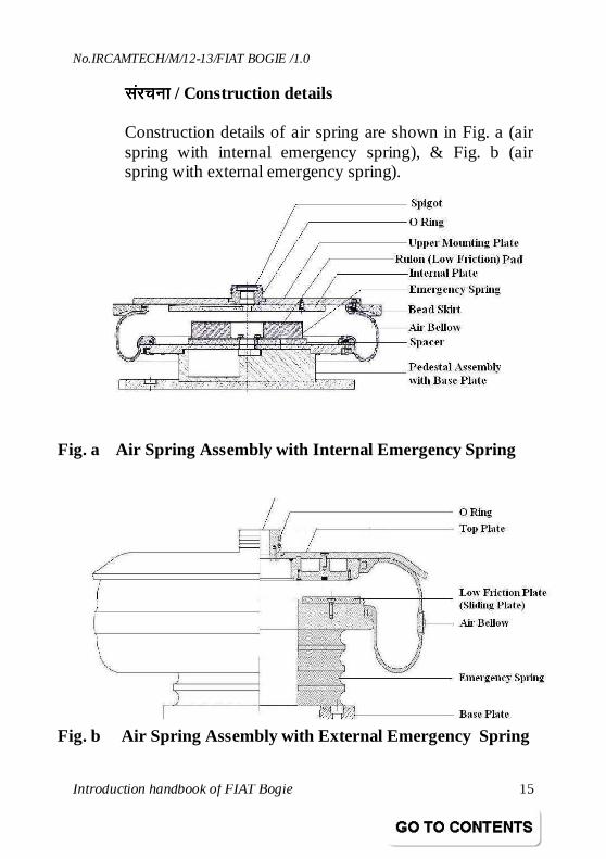
lajpuklajpuklajpuklajpuk / Construction details
Construction details of air spring are shown in Fig. a (air spring with internal emergency spring), & Fig. b (air spring with external emergency spring).
Fig. a Air Spring Assembly with Internal Emergency Spring
Fig. b Air Spring Assembly with External Emergency Spring
No.IRCAMTECH/M/12-13/FIAT BOGIE /1.0
Introduction handbook of FIAT Bogie 16
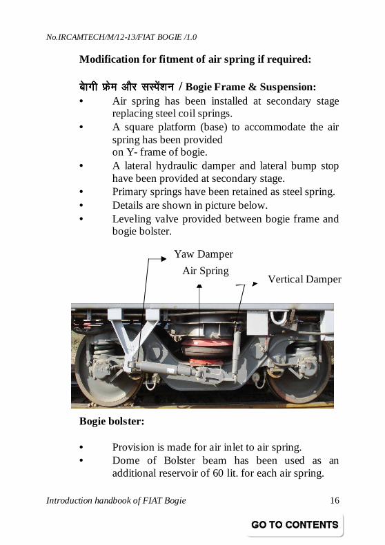
Modification for fitment of air spring if required:
CksCksCksCkskkkkxh Ýxh Ýxh Ýxh Ýse vkSj lLisa’kuse vkSj lLisa’kuse vkSj lLisa’kuse vkSj lLisa’ku / Bogie Frame & Suspension: • Air spring has been installed at secondary stage
replacing steel coil springs. • A square platform (base) to accommodate the air
spring has been provided on Y- frame of bogie.
• A lateral hydraulic damper and lateral bump stop have been provided at secondary stage.
• Primary springs have been retained as steel spring. • Details are shown in picture below. • Leveling valve provided between bogie frame and
bogie bolster. Bogie bolster: • Provision is made for air inlet to air spring. • Dome of Bolster beam has been used as an
additional reservoir of 60 lit. for each air spring.
Yaw Damper
Vertical Damper Air Spring
No.IRCAMTECH/M/12-13/FIAT BOGIE /1.0
Introduction handbook of FIAT Bogie 17
• Duplex check valve is provided. vUMj vUMj vUMj vUMj ÝÝÝÝse se se se /Under frame: • A pipeline is drawn from M.R pipe (feed pipe) for
pneumatic suspension. • One isolating cock, one non return valve, one 150
lit air reservoir (auxiliary reservoir) one air filter and two separate isolating cocks to isolate each bogie have been provided.
csl IysV csl IysV csl IysV csl IysV / Base plate:
• Base plate shall be as per drawing No. RDSO CG- K5057 alt ‘b’.
No.IRCAMTECH/M/12-13/FIAT BOGIE /1.0
Introduction handbook of FIAT Bogie 18
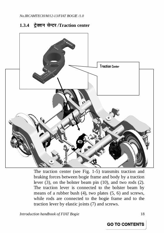
1.3.4 VªsD’ku VªsD’ku VªsD’ku VªsD’ku lsUVjlsUVjlsUVjlsUVj /Traction center
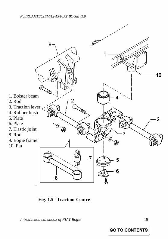
The traction center (see Fig. 1-5) transmits traction and braking forces between bogie frame and body by a traction lever (3), on the bolster beam pin (10), and two rods (2). The traction lever is connected to the bolster beam by means of a rubber bush (4), two plates (5, 6) and screws, while rods are connected to the bogie frame and to the traction lever by elastic joints (7) and screws.
Traction Center
No.IRCAMTECH/M/12-13/FIAT BOGIE /1.0
Introduction handbook of FIAT Bogie 19
1. Bolster beam 2. Rod 3. Traction lever 4. Rubber bush 5. Plate 6. Plate 7. Elastic joint 8. Rod 9. Bogie frame 10. Pin
Fig. 1.5 Traction Centre
No.IRCAMTECH/M/12-13/FIAT BOGIE /1.0
Introduction handbook of FIAT Bogie 20
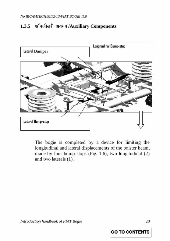
1.3.5 vkWDthyjh vo;ovkWDthyjh vo;ovkWDthyjh vo;ovkWDthyjh vo;o /Auxiliary Components
The bogie is completed by a device for limiting the longitudinal and lateral displacements of the bolster beam, made by four bump stops (Fig. 1.6), two longitudinal (2) and two laterals (1).
Lateral Damper
Lateral Bump-stop
Longitudinal Bump-stop
No.IRCAMTECH/M/12-13/FIAT BOGIE /1.0
Introduction handbook of FIAT Bogie 21
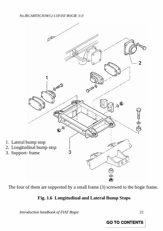
The four of them are supported by a small frame (3) screwed to the bogie frame.
Fig. 1.6 Longitudinal and Lateral Bump Stops
1. Lateral bump stop 2. Longitudinal bump stop 3. Support- frame
No.IRCAMTECH/M/12-13/FIAT BOGIE /1.0
Introduction handbook of FIAT Bogie 22
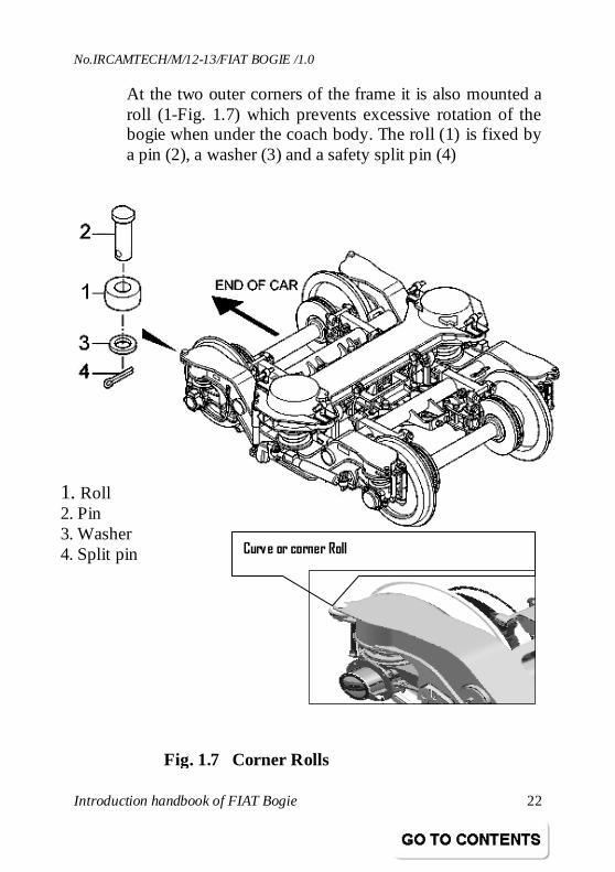
At the two outer corners of the frame it is also mounted a roll (1-Fig. 1.7) which prevents excessive rotation of the bogie when under the coach body. The roll (1) is fixed by a pin (2), a washer (3) and a safety split pin (4)
Curve or corner Roll
1. Roll 2. Pin 3. Washer 4. Split pin
Fig. 1.7 Corner Rolls
No.IRCAMTECH/M/12-13/FIAT BOGIE /1.0
Introduction handbook of FIAT Bogie 23
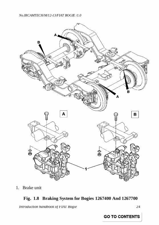
1.3.6 bULVkWYM czsfdax iöfrbULVkWYM czsfdax iöfrbULVkWYM czsfdax iöfrbULVkWYM czsfdax iöfr / Installed Braking Systems
The pneumatic braking systems acting on the bogie are as follows:
• Pneumatic disk braking only (see Fig. 1.8), covering the whole speed range and acting on both axles for bogies 1267400 and 1267700.
• Pneumatic disk braking and hand-operated brakes acting on both axles for bogie 1267334.
Pneumatic braking is implemented by pneumatically operated brake cylinders fitted with an automatic device for taking up clearances. Air to spring brake cylinders is supplied through two compressed air pipes, one for the brakes of the first axle, and the other for the second axle. Brake cylinder action is transmitted, through two levers and a balancing arm, to a pair of pad holders, which perform braking on relevant disk.
No.IRCAMTECH/M/12-13/FIAT BOGIE /1.0
Introduction handbook of FIAT Bogie 24
1. Brake unit
Fig. 1.8 Braking System for Bogies 1267400 And 1267700
No.IRCAMTECH/M/12-13/FIAT BOGIE /1.0
Introduction handbook of FIAT Bogie 25
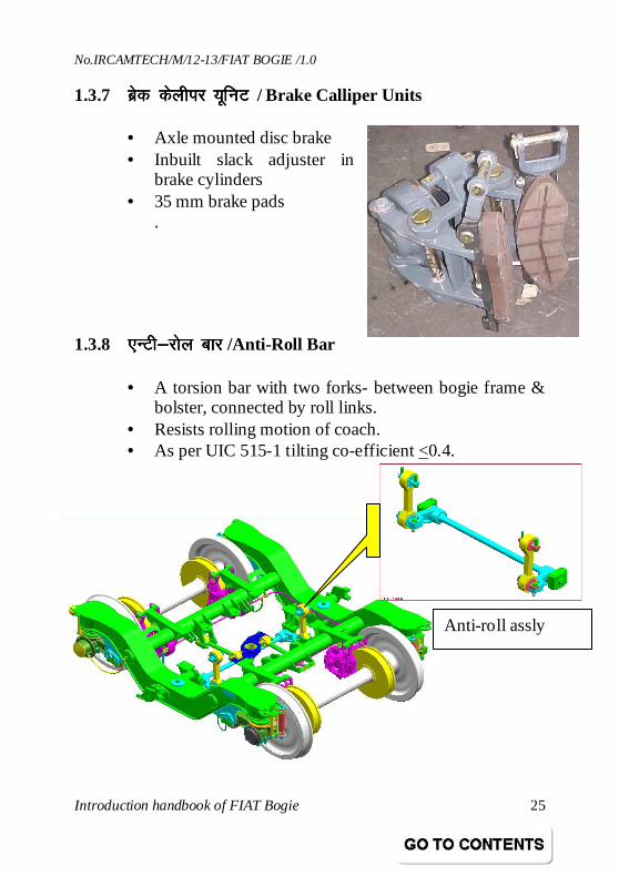
1.3.7 czsd dsyhij ;wfuV czsd dsyhij ;wfuV czsd dsyhij ;wfuV czsd dsyhij ;wfuV / Brake Calliper Units
• Axle mounted disc brake • Inbuilt slack adjuster in
brake cylinders • 35 mm brake pads
. 1.3.8 ,UVh&jksy ckj,UVh&jksy ckj,UVh&jksy ckj,UVh&jksy ckj /Anti-Roll Bar
• A torsion bar with two forks- between bogie frame & bolster, connected by roll links.
• Resists rolling motion of coach. • As per UIC 515-1 tilting co-efficient <0.4.
Anti-roll assly
No.IRCAMTECH/M/12-13/FIAT BOGIE /1.0
Introduction handbook of FIAT Bogie 26
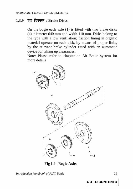
1.3.9 czsd fMLdlczsd fMLdlczsd fMLdlczsd fMLdl / Brake Discs
On the bogie each axle (1) is fitted with two brake disks (4), diameter 640 mm and width 110 mm. Disks belong to the type with a low ventilation; friction lining in organic material operate on each disk, by means of proper links, by the relevant brake cylinder fitted with an automatic device for taking up clearances. Note: Please refer to chapter on Air Brake system for more details
Fig 1.9 Bogie Axles
No.IRCAMTECH/M/12-13/FIAT BOGIE /1.0
Introduction handbook of FIAT Bogie 27
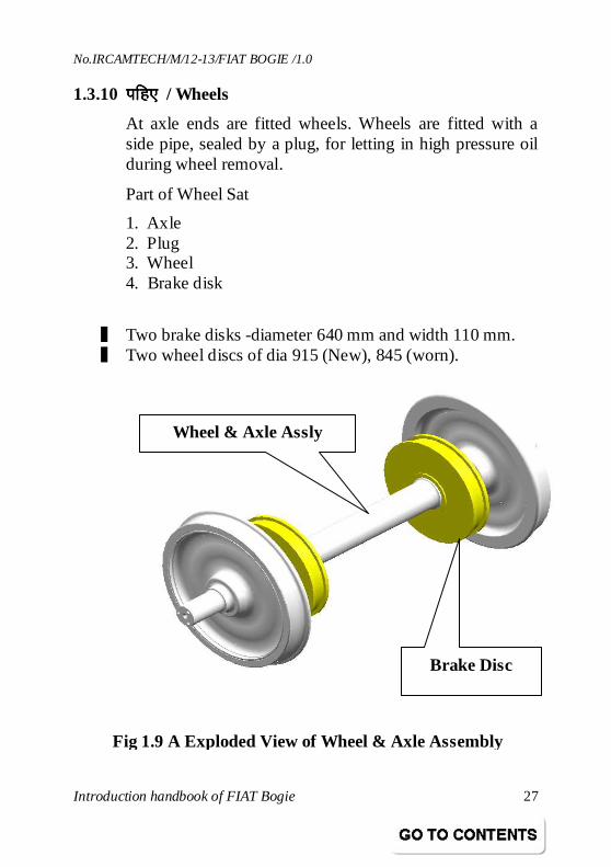
1.3.10 ifg,ifg,ifg,ifg, / Wheels
At axle ends are fitted wheels. Wheels are fitted with a side pipe, sealed by a plug, for letting in high pressure oil during wheel removal.
Part of Wheel Sat
❚ Two brake disks -diameter 640 mm and width 110 mm. ❚ Two wheel discs of dia 915 (New), 845 (worn).
1. Axle 2. Plug 3. Wheel 4. Brake disk
Wheel & Axle Assly
Brake Disc
Fig 1.9 A Exploded View of Wheel & Axle Assembly
No.IRCAMTECH/M/12-13/FIAT BOGIE /1.0
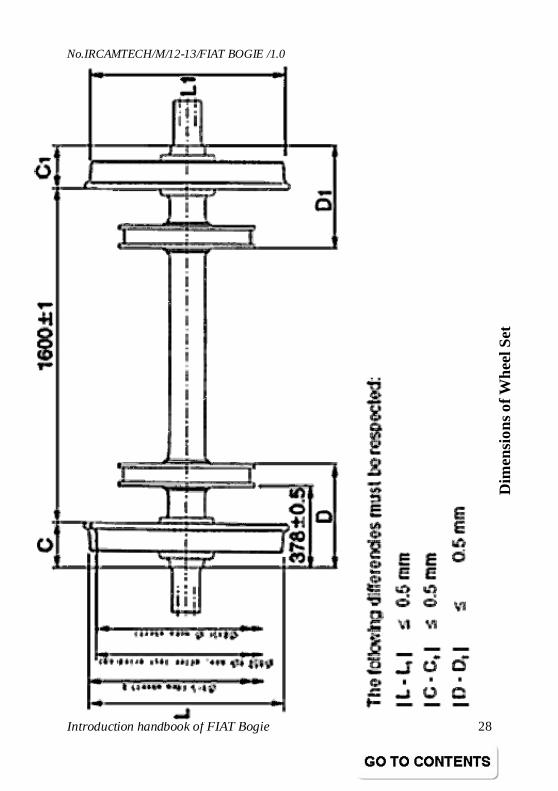
Introduction handbook of FIAT Bogie 28
Dim
ensi
ons o
f Whe
el S
et
No.IRCAMTECH/M/12-13/FIAT BOGIE /1.0
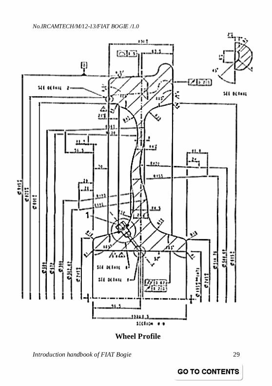
Introduction handbook of FIAT Bogie 29
Wheel Profile
No.IRCAMTECH/M/12-13/FIAT BOGIE /1.0
Introduction handbook of FIAT Bogie 30
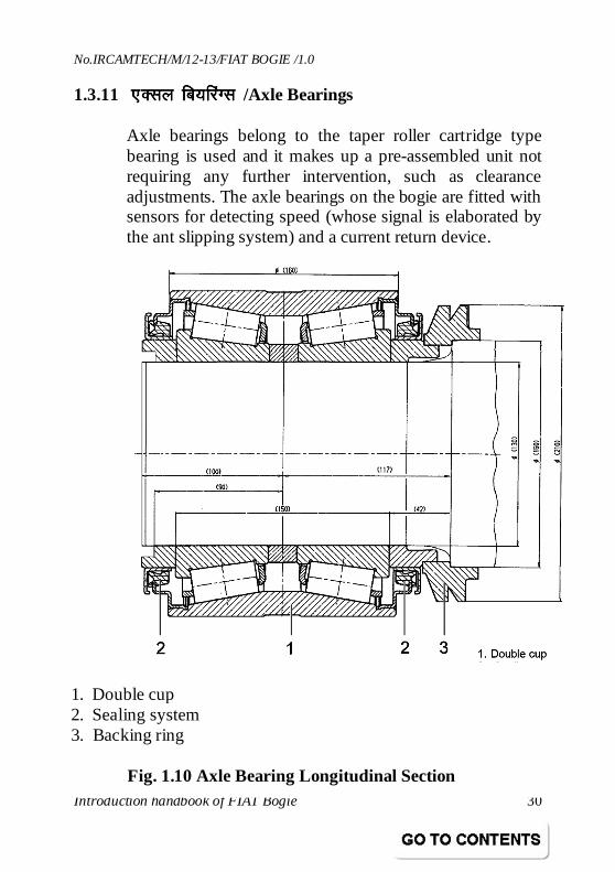
1.3.11 ,Dly fc;fjaXl ,Dly fc;fjaXl ,Dly fc;fjaXl ,Dly fc;fjaXl /Axle Bearings
Axle bearings belong to the taper roller cartridge type bearing is used and it makes up a pre-assembled unit not requiring any further intervention, such as clearance adjustments. The axle bearings on the bogie are fitted with sensors for detecting speed (whose signal is elaborated by the ant slipping system) and a current return device.
1. Double cup 2. Sealing system 3. Backing ring
Fig. 1.10 Axle Bearing Longitudinal Section
No.IRCAMTECH/M/12-13/FIAT BOGIE /1.0
Introduction handbook of FIAT Bogie 31
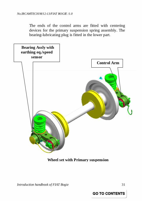
Control Arm
The ends of the control arms are fitted with centering devices for the primary suspension spring assembly. The bearing-lubricating plug is fitted in the lower part.
Bearing Assly with earthing eq./speed
sensor
Wheel set with Primary suspension
No.IRCAMTECH/M/12-13/FIAT BOGIE /1.0
Introduction handbook of FIAT Bogie 32
1.4 QkslZ VªkUleh’ku ds fl)kUrQkslZ VªkUleh’ku ds fl)kUrQkslZ VªkUleh’ku ds fl)kUrQkslZ VªkUleh’ku ds fl)kUr / Principles of force transmissions
Forces concerning the bogie are transmitted as follows. Vertical forces: from the body to the bogie frame- through the secondary suspension springs; from the bogie frame to the axles- through the primary suspension springs and frame - axle bearing control arm. Crosswise forces: from the body to the bogie frame- through the secondary suspension springs; from the bogie frame to the axles- through the elastic elements of the frame – axle bearing control arm. Longitudinal traction efforts and braking powers: from the body to bogie frame- through the traction center rods and the traction lever; from the bogie frame to the axles through the frame - axle bearing control arm.
No.IRCAMTECH/M/12-13/FIAT BOGIE /1.0
Introduction handbook of FIAT Bogie 33
2.0 dksp ckWMh dk mBkukdksp ckWMh dk mBkukdksp ckWMh dk mBkukdksp ckWMh dk mBkuk / LIFTING THE BODY
WARNING: Before lifting the coach body or the complete coach, check the primary lift pins and the secondary security cables and pins.
2.1 cksxh ds foPNsn Øe cksxh ds foPNsn Øe cksxh ds foPNsn Øe cksxh ds foPNsn Øe / Bogie disconnection sequence
In order to disconnect the bogie from the coach body, follow this sequence: • Disconnect the pneumatic connections of the brakes.
Disconnect the cables of the hand brake (just for bogie 1267334)
• Disconnect the electric cables from the sensors mounted on the axle bearings
• Disconnect the ground cable between coach body and bogie frame.
• Disconnect the yaw dampers from the coach body. • Disconnect the bolster beam from the coach bottom. • Lift the coach body. • Roll the bogie away
No.IRCAMTECH/M/12-13/FIAT BOGIE /1.0
Introduction handbook of FIAT Bogie 34
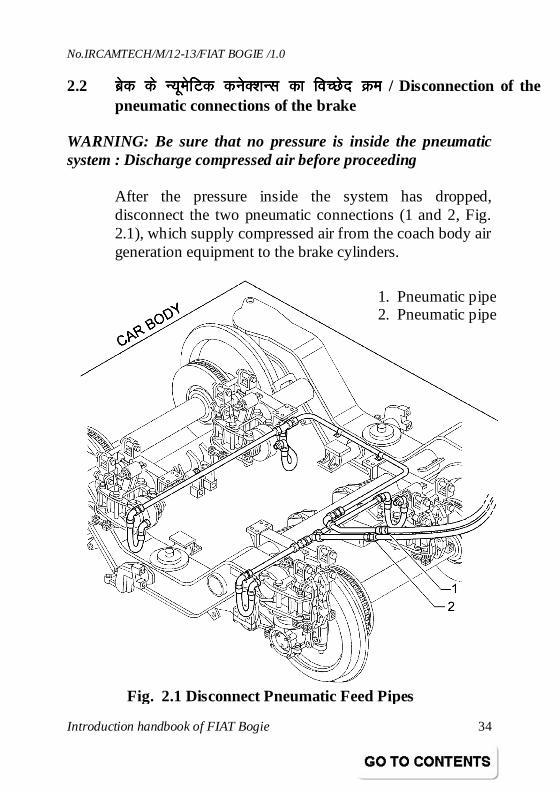
2.2 czsd ds U;wesfVd dusD’kUl dk foPNsnczsd ds U;wesfVd dusD’kUl dk foPNsnczsd ds U;wesfVd dusD’kUl dk foPNsnczsd ds U;wesfVd dusD’kUl dk foPNsn Øe Øe Øe Øe / Disconnection of the pneumatic connections of the brake
WARNING: Be sure that no pressure is inside the pneumatic system : Discharge compressed air before proceeding
After the pressure inside the system has dropped, disconnect the two pneumatic connections (1 and 2, Fig. 2.1), which supply compressed air from the coach body air generation equipment to the brake cylinders.
1. Pneumatic pipe 2. Pneumatic pipe
Fig. 2.1 Disconnect Pneumatic Feed Pipes
No.IRCAMTECH/M/12-13/FIAT BOGIE /1.0
Introduction handbook of FIAT Bogie 35
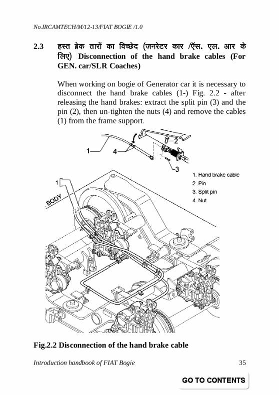
2.3 gLr czsd rkjksa dk foPNsn ¼gLr czsd rkjksa dk foPNsn ¼gLr czsd rkjksa dk foPNsn ¼gLr czsd rkjksa dk foPNsn ¼tujsVj dkjtujsVj dkjtujsVj dkjtujsVj dkj /,Wl,Wl,Wl,Wl. ,y ,y ,y ,y. vkj vkj vkj vkj ds ds ds ds fy,½ fy,½ fy,½ fy,½ Disconnection of the hand brake cables (For GEN. car/SLR Coaches)
When working on bogie of Generator car it is necessary to disconnect the hand brake cables (1-) Fig. 2.2 - after releasing the hand brakes: extract the split pin (3) and the pin (2), then un-tighten the nuts (4) and remove the cables (1) from the frame support.
Fig.2.2 Disconnection of the hand brake cable
No.IRCAMTECH/M/12-13/FIAT BOGIE /1.0
Introduction handbook of FIAT Bogie 36
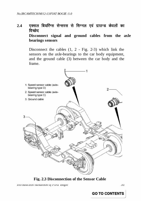
2.4 ,Dly fc;fjaXl lsUljl ls flXuy ,oa xzkmUM dsoyksa dk ,Dly fc;fjaXl lsUljl ls flXuy ,oa xzkmUM dsoyksa dk ,Dly fc;fjaXl lsUljl ls flXuy ,oa xzkmUM dsoyksa dk ,Dly fc;fjaXl lsUljl ls flXuy ,oa xzkmUM dsoyksa dk foPNsnfoPNsnfoPNsnfoPNsn Disconnect signal and ground cables from the axle bearings sensors
Disconnect the cables (1, 2 - Fig. 2-3) which link the sensors on the axle-bearings to the car body equipment, and the ground cable (3) between the car body and the frame.
Fig. 2.3 Disconnection of the Sensor Cable
No.IRCAMTECH/M/12-13/FIAT BOGIE /1.0
Introduction handbook of FIAT Bogie 37
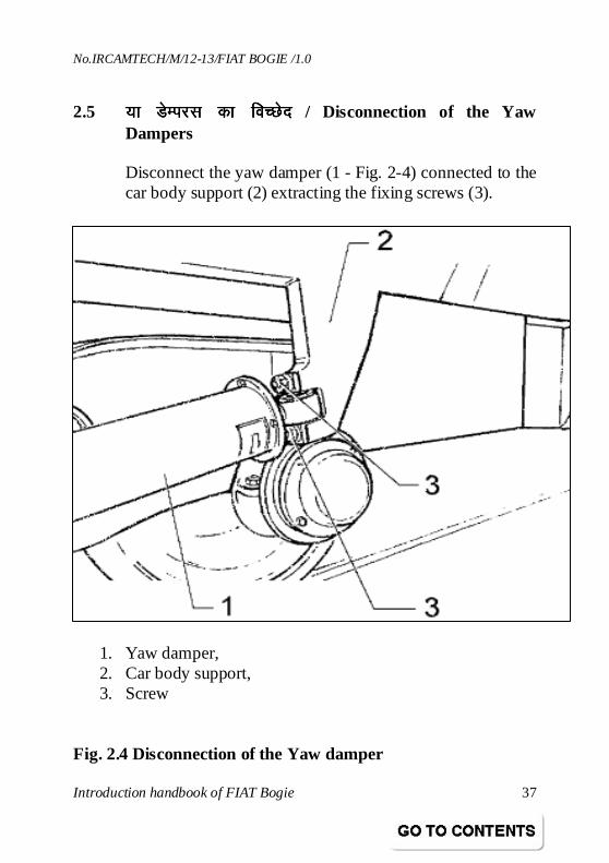
2.5 ;k MsEijl dk foPNsn;k MsEijl dk foPNsn;k MsEijl dk foPNsn;k MsEijl dk foPNsn / Disconnection of the Yaw Dampers
Disconnect the yaw damper (1 - Fig. 2-4) connected to the car body support (2) extracting the fixing screws (3).
1. Yaw damper, 2. Car body support, 3. Screw
Fig. 2.4 Disconnection of the Yaw damper
No.IRCAMTECH/M/12-13/FIAT BOGIE /1.0
Introduction handbook of FIAT Bogie 38
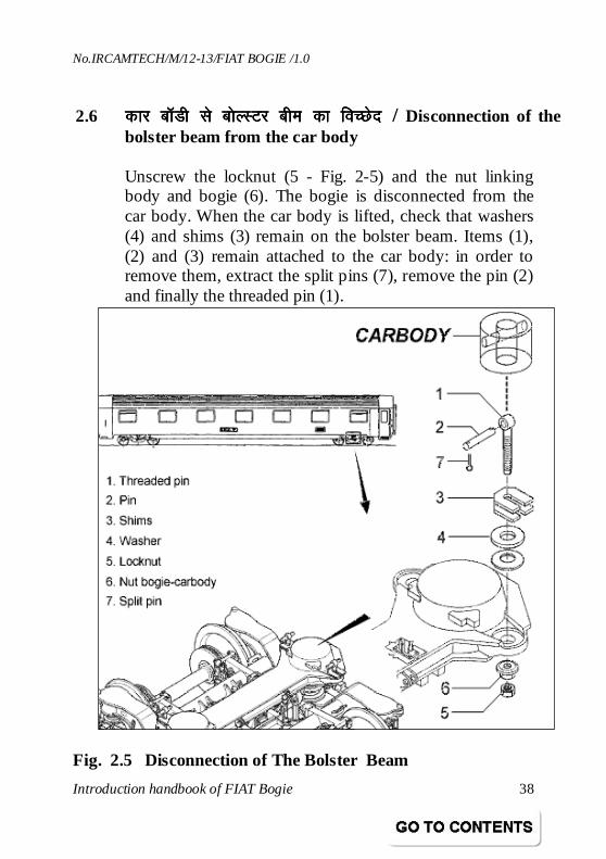
2.6 dkj ckWMh ls cksYLVj che dk foPNsn dkj ckWMh ls cksYLVj che dk foPNsn dkj ckWMh ls cksYLVj che dk foPNsn dkj ckWMh ls cksYLVj che dk foPNsn / Disconnection of the
bolster beam from the car body
Unscrew the locknut (5 - Fig. 2-5) and the nut linking body and bogie (6). The bogie is disconnected from the car body. When the car body is lifted, check that washers (4) and shims (3) remain on the bolster beam. Items (1), (2) and (3) remain attached to the car body: in order to remove them, extract the split pins (7), remove the pin (2) and finally the threaded pin (1).
Fig. 2.5 Disconnection of The Bolster Beam
No.IRCAMTECH/M/12-13/FIAT BOGIE /1.0
Introduction handbook of FIAT Bogie 39
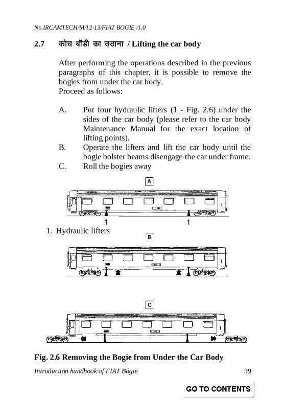
2.7 dksp ckWMh dk mBkukdksp ckWMh dk mBkukdksp ckWMh dk mBkukdksp ckWMh dk mBkuk / Lifting the car body
After performing the operations described in the previous paragraphs of this chapter, it is possible to remove the bogies from under the car body. Proceed as follows: A. Put four hydraulic lifters (1 - Fig. 2.6) under the
sides of the car body (please refer to the car body Maintenance Manual for the exact location of lifting points).
B. Operate the lifters and lift the car body until the bogie bolster beams disengage the car under frame.
C. Roll the bogies away
Fig. 2.6 Removing the Bogie from Under the Car Body
1. Hydraulic lifters
No.IRCAMTECH/M/12-13/FIAT BOGIE /1.0
Introduction handbook of FIAT Bogie 40
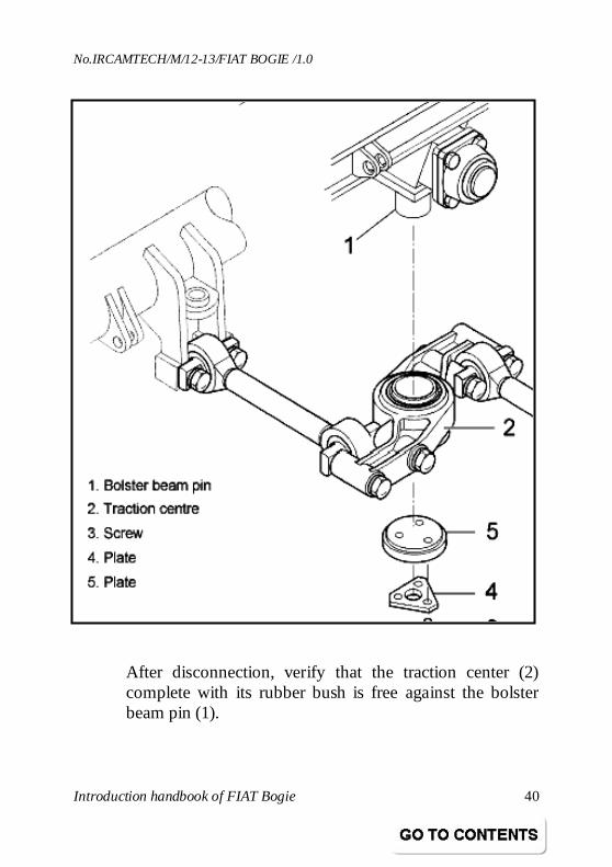
After disconnection, verify that the traction center (2) complete with its rubber bush is free against the bolster beam pin (1).
No.IRCAMTECH/M/12-13/FIAT BOGIE /1.0
Introduction handbook of FIAT Bogie 41
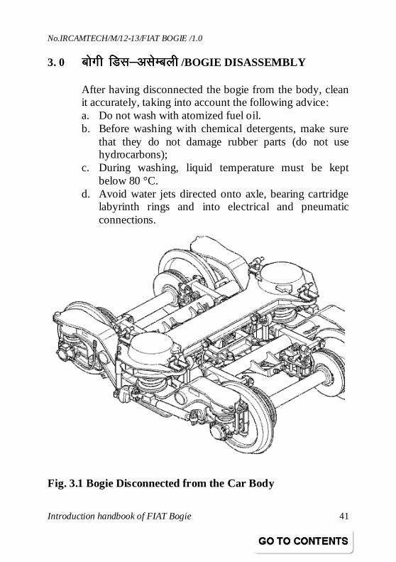
3. 0 Ckksxh fMl&vlsEcyhCkksxh fMl&vlsEcyhCkksxh fMl&vlsEcyhCkksxh fMl&vlsEcyh /BOGIE DISASSEMBLY
After having disconnected the bogie from the body, clean it accurately, taking into account the following advice: a. Do not wash with atomized fuel oil. b. Before washing with chemical detergents, make sure
that they do not damage rubber parts (do not use hydrocarbons);
c. During washing, liquid temperature must be kept below 80 °C.
d. Avoid water jets directed onto axle, bearing cartridge labyrinth rings and into electrical and pneumatic connections.
Fig. 3.1 Bogie Disconnected from the Car Body
No.IRCAMTECH/M/12-13/FIAT BOGIE /1.0
Introduction handbook of FIAT Bogie 42
3.1 lsdsUMªh lLias’ku fMlekmfUVaxlsdsUMªh lLias’ku fMlekmfUVaxlsdsUMªh lLias’ku fMlekmfUVaxlsdsUMªh lLias’ku fMlekmfUVax / Secondary suspension dismounting
In order to completely remove the secondary suspension from the bogie it is necessary to perform the operations described in the following paragraphs.
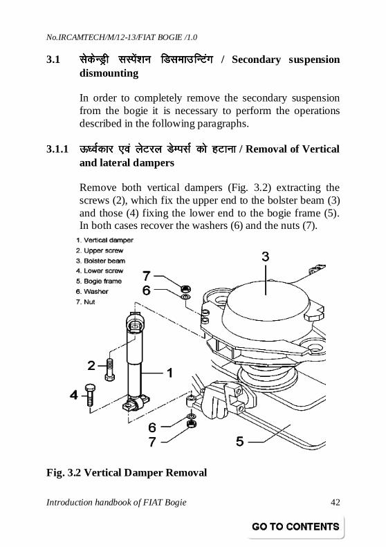
3.1.1 ÅËoZdkj ,oa ysVjy MsEilZ dks gVkukÅËoZdkj ,oa ysVjy MsEilZ dks gVkukÅËoZdkj ,oa ysVjy MsEilZ dks gVkukÅËoZdkj ,oa ysVjy MsEilZ dks gVkuk / Removal of Vertical
and lateral dampers
Remove both vertical dampers (Fig. 3.2) extracting the screws (2), which fix the upper end to the bolster beam (3) and those (4) fixing the lower end to the bogie frame (5). In both cases recover the washers (6) and the nuts (7).
Fig. 3.2 Vertical Damper Removal
No.IRCAMTECH/M/12-13/FIAT BOGIE /1.0
Introduction handbook of FIAT Bogie 43
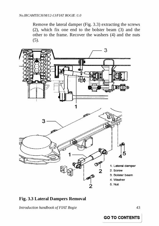
Remove the lateral damper (Fig. 3.3) extracting the screws (2), which fix one end to the bolster beam (3) and the other to the frame. Recover the washers (4) and the nuts (5).
Fig. 3.3 Lateral Dampers Removal
No.IRCAMTECH/M/12-13/FIAT BOGIE /1.0
Introduction handbook of FIAT Bogie 44
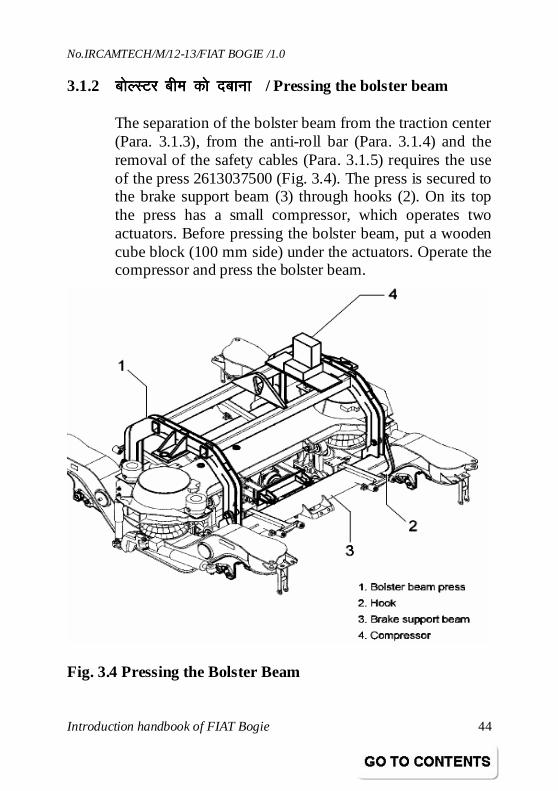
3.1.2 cksYLVj che dks nckuk cksYLVj che dks nckuk cksYLVj che dks nckuk cksYLVj che dks nckuk / Pressing the bolster beam
The separation of the bolster beam from the traction center (Para. 3.1.3), from the anti-roll bar (Para. 3.1.4) and the removal of the safety cables (Para. 3.1.5) requires the use of the press 2613037500 (Fig. 3.4). The press is secured to the brake support beam (3) through hooks (2). On its top the press has a small compressor, which operates two actuators. Before pressing the bolster beam, put a wooden cube block (100 mm side) under the actuators. Operate the compressor and press the bolster beam.
Fig. 3.4 Pressing the Bolster Beam
No.IRCAMTECH/M/12-13/FIAT BOGIE /1.0
Introduction handbook of FIAT Bogie 45
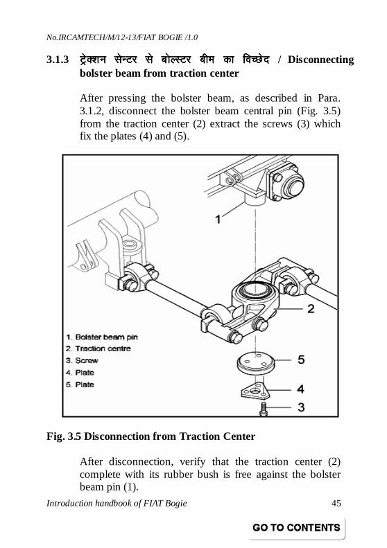
3.1.3 VªsD’ku VªsD’ku VªsD’ku VªsD’ku lsUVj lsUVj lsUVj lsUVj ls cksYLVj che dk foPNsn ls cksYLVj che dk foPNsn ls cksYLVj che dk foPNsn ls cksYLVj che dk foPNsn / Disconnecting bolster beam from traction center
After pressing the bolster beam, as described in Para. 3.1.2, disconnect the bolster beam central pin (Fig. 3.5) from the traction center (2) extract the screws (3) which fix the plates (4) and (5).
Fig. 3.5 Disconnection from Traction Center
After disconnection, verify that the traction center (2) complete with its rubber bush is free against the bolster beam pin (1).
No.IRCAMTECH/M/12-13/FIAT BOGIE /1.0
Introduction handbook of FIAT Bogie 46
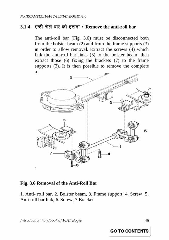
3.1.4 ,UVh jksy ckj dks gVkuk ,UVh jksy ckj dks gVkuk ,UVh jksy ckj dks gVkuk ,UVh jksy ckj dks gVkuk / Remove the anti-roll bar
The anti-roll bar (Fig. 3.6) must be disconnected both from the bolster beam (2) and from the frame supports (3) in order to allow removal. Extract the screws (4) which link the anti-roll bar links (5) to the bolster beam, then extract those (6) fixing the brackets (7) to the frame supports (3). It is then possible to remove the complete anti-roll bar (1).
Fig. 3.6 Removal of the Anti-Roll Bar 1. Anti- roll bar, 2. Bolster beam, 3. Frame support, 4. Screw, 5. Anti-roll bar link, 6. Screw, 7 Bracket
No.IRCAMTECH/M/12-13/FIAT BOGIE /1.0
Introduction handbook of FIAT Bogie 47
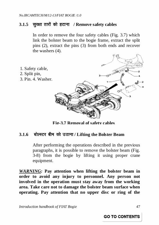
3.1.5 lqj{kk rkjksa dks gVkuk lqj{kk rkjksa dks gVkuk lqj{kk rkjksa dks gVkuk lqj{kk rkjksa dks gVkuk / Remove safety cables
In order to remove the four safety cables (Fig. 3.7) which link the bolster beam to the bogie frame, extract the split pins (2), extract the pins (3) from both ends and recover the washers (4).
3.1.6 cksYLVj che dks mBkukcksYLVj che dks mBkukcksYLVj che dks mBkukcksYLVj che dks mBkuk / Lifting the Bolster Beam
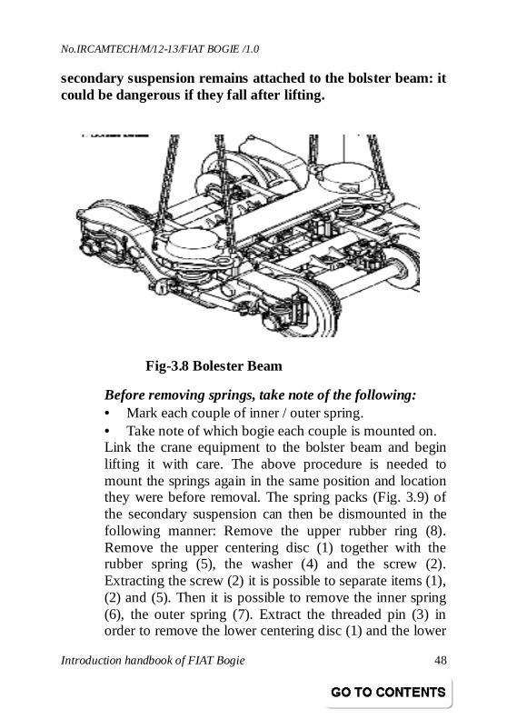
After performing the operations described in the previous paragraphs, it is possible to remove the bolster beam (Fig. 3-8) from the bogie by lifting it using proper crane equipment.
WARNING: Pay attention when lifting the bolster beam in order to avoid any injury to personnel. Any person not involved in the operation must stay away from the working area. Take care not to damage the bolster beam surface when operating. Pay attention that no upper disc or ring of the
Fig-3.7 Removal of safety cables
1. Safety cable, 2. Split pin, 3. Pin. 4. Washer.
No.IRCAMTECH/M/12-13/FIAT BOGIE /1.0
Introduction handbook of FIAT Bogie 48
secondary suspension remains attached to the bolster beam: it could be dangerous if they fall after lifting.
Before removing springs, take note of the following: • Mark each couple of inner / outer spring. • Take note of which bogie each couple is mounted on. Link the crane equipment to the bolster beam and begin lifting it with care. The above procedure is needed to mount the springs again in the same position and location they were before removal. The spring packs (Fig. 3.9) of the secondary suspension can then be dismounted in the following manner: Remove the upper rubber ring (8). Remove the upper centering disc (1) together with the rubber spring (5), the washer (4) and the screw (2). Extracting the screw (2) it is possible to separate items (1), (2) and (5). Then it is possible to remove the inner spring (6), the outer spring (7). Extract the threaded pin (3) in order to remove the lower centering disc (1) and the lower
Fig-3.8 Bolester Beam
No.IRCAMTECH/M/12-13/FIAT BOGIE /1.0
Introduction handbook of FIAT Bogie 49
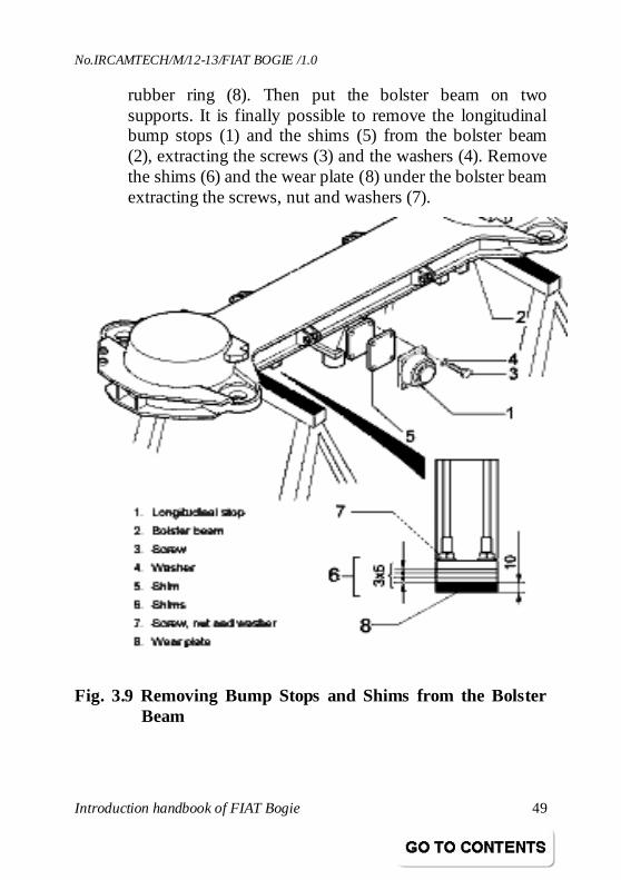
rubber ring (8). Then put the bolster beam on two supports. It is finally possible to remove the longitudinal bump stops (1) and the shims (5) from the bolster beam (2), extracting the screws (3) and the washers (4). Remove the shims (6) and the wear plate (8) under the bolster beam extracting the screws, nut and washers (7).
Fig. 3.9 Removing Bump Stops and Shims from the Bolster Beam
No.IRCAMTECH/M/12-13/FIAT BOGIE /1.0
Introduction handbook of FIAT Bogie 50
3.2 Ýse ls fMLvlsEcyht dk fcPNsnu Ýse ls fMLvlsEcyht dk fcPNsnu Ýse ls fMLvlsEcyht dk fcPNsnu Ýse ls fMLvlsEcyht dk fcPNsnu / Dismounting assemblies from the frame
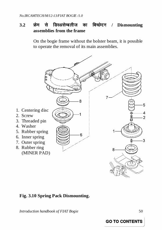
On the bogie frame without the bolster beam, it is possible to operate the removal of its main assemblies.
Fig. 3.10 Spring Pack Dismounting.
1. Centering disc 2. Screw 3. Threaded pin 4. Washer 5. Rubber spring 6. Inner spring 7. Outer spring 8. Rubber ring (MINER PAD)
No.IRCAMTECH/M/12-13/FIAT BOGIE /1.0
Introduction handbook of FIAT Bogie 51
3.2.1 ;k MsEilZ dsk gVkuk;k MsEilZ dsk gVkuk;k MsEilZ dsk gVkuk;k MsEilZ dsk gVkuk / Removal of Yaw Dampers
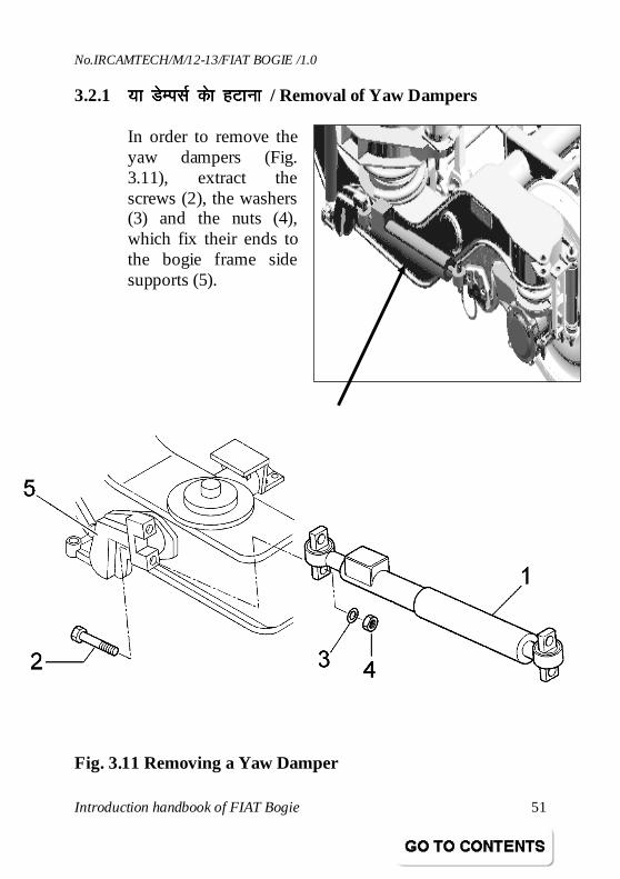
In order to remove the yaw dampers (Fig. 3.11), extract the screws (2), the washers (3) and the nuts (4), which fix their ends to the bogie frame side supports (5).
Fig. 3.11 Removing a Yaw Damper
No.IRCAMTECH/M/12-13/FIAT BOGIE /1.0
Introduction handbook of FIAT Bogie 52
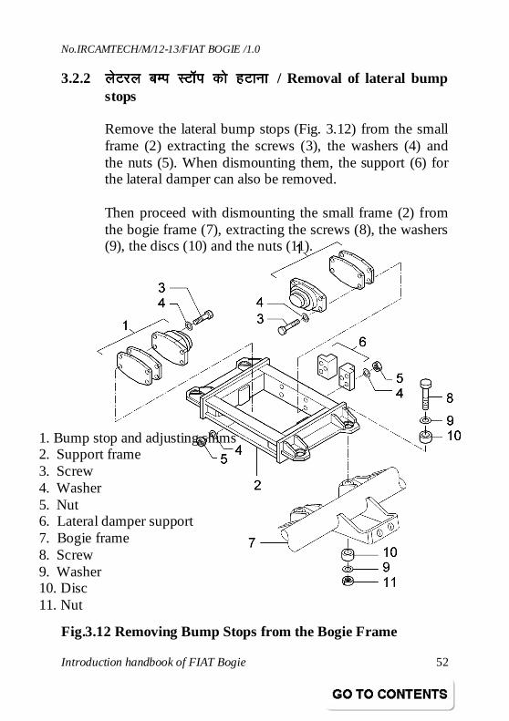
3.2.2 ysVjy cEi LVkWi dks gVkuk ysVjy cEi LVkWi dks gVkuk ysVjy cEi LVkWi dks gVkuk ysVjy cEi LVkWi dks gVkuk / Removal of lateral bump stops
Remove the lateral bump stops (Fig. 3.12) from the small frame (2) extracting the screws (3), the washers (4) and the nuts (5). When dismounting them, the support (6) for the lateral damper can also be removed. Then proceed with dismounting the small frame (2) from the bogie frame (7), extracting the screws (8), the washers (9), the discs (10) and the nuts (11).
Fig.3.12 Removing Bump Stops from the Bogie Frame
1. Bump stop and adjusting shims 2. Support frame 3. Screw 4. Washer 5. Nut 6. Lateral damper support 7. Bogie frame 8. Screw 9. Washer 10. Disc 11. Nut
No.IRCAMTECH/M/12-13/FIAT BOGIE /1.0
Introduction handbook of FIAT Bogie 53
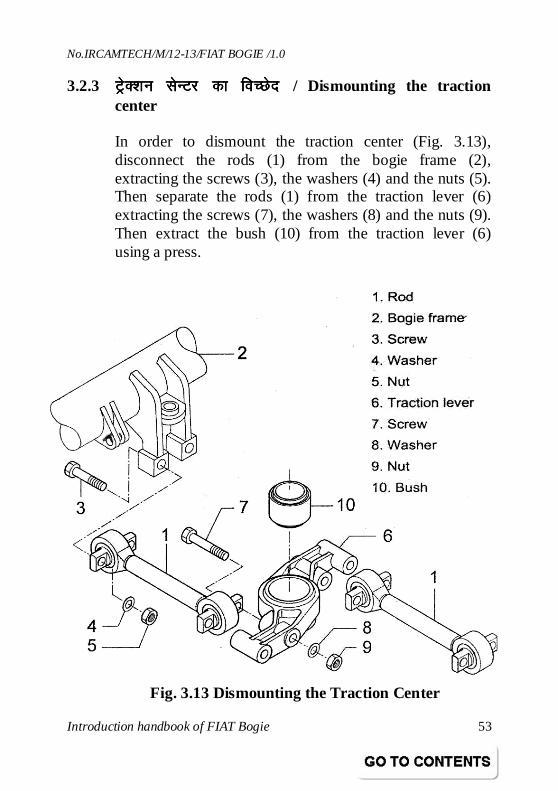
3.2.3 VªsD’ku lsUVj dk foPNsnVªsD’ku lsUVj dk foPNsnVªsD’ku lsUVj dk foPNsnVªsD’ku lsUVj dk foPNsn / Dismounting the traction center
In order to dismount the traction center (Fig. 3.13), disconnect the rods (1) from the bogie frame (2), extracting the screws (3), the washers (4) and the nuts (5). Then separate the rods (1) from the traction lever (6) extracting the screws (7), the washers (8) and the nuts (9). Then extract the bush (10) from the traction lever (6) using a press.
Fig. 3.13 Dismounting the Traction Center
No.IRCAMTECH/M/12-13/FIAT BOGIE /1.0
Introduction handbook of FIAT Bogie 54
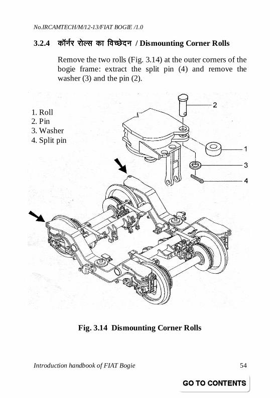
3.2.4 dkWuZZj jksYl dk foPNsnudkWuZZj jksYl dk foPNsnudkWuZZj jksYl dk foPNsnudkWuZZj jksYl dk foPNsnu / Dismounting Corner Rolls
Remove the two rolls (Fig. 3.14) at the outer corners of the bogie frame: extract the split pin (4) and remove the washer (3) and the pin (2).
Fig. 3.14 Dismounting Corner Rolls
1. Roll 2. Pin 3. Washer 4. Split pin
No.IRCAMTECH/M/12-13/FIAT BOGIE /1.0
Introduction handbook of FIAT Bogie 55
3.2.5 U;wesfVd ;a= dk fcPNsnu U;wesfVd ;a= dk fcPNsnu U;wesfVd ;a= dk fcPNsnu U;wesfVd ;a= dk fcPNsnu / Dismounting the pneumatic equipment
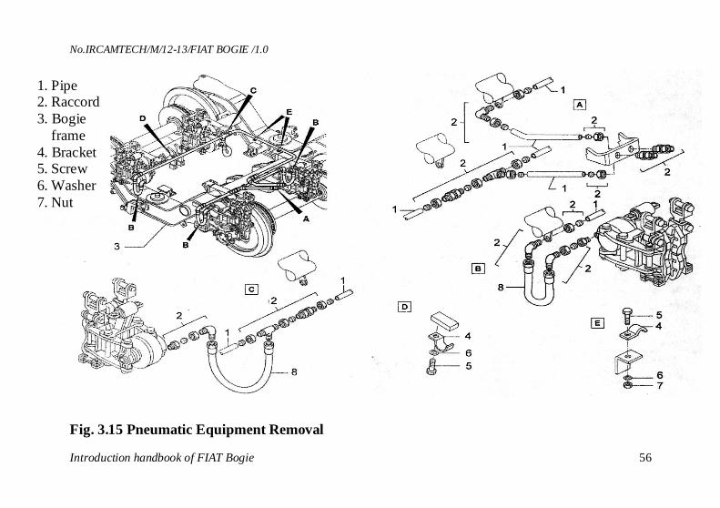
The pneumatic equipment (see Fig. 3.15) of the brakes can be dismounted into its simple components and completely removed from the bogie. Warning: Before proceeding be sure that no pneumatic feed is connected to the system and that no pressure is inside. The complete equipment is made of several pipes (1) and hoses (8) connected together by various types of records (2). The pipes are kept into position on the bogie frame (3) by means of brackets (4) fixed to the frame by screws (5), washers (6) and nuts (7).
No.IRCAMTECH/M/12-13/FIAT BOGIE /1.0
Introduction handbook of FIAT Bogie 56
Fig. 3.15 Pneumatic Equipment Removal
1. Pipe 2. Raccord 3. Bogie frame 4. Bracket 5. Screw 6. Washer 7. Nut 8. Hose
No.IRCAMTECH/M/12-13/FIAT BOGIE /1.0
Introduction handbook of FIAT Bogie 57
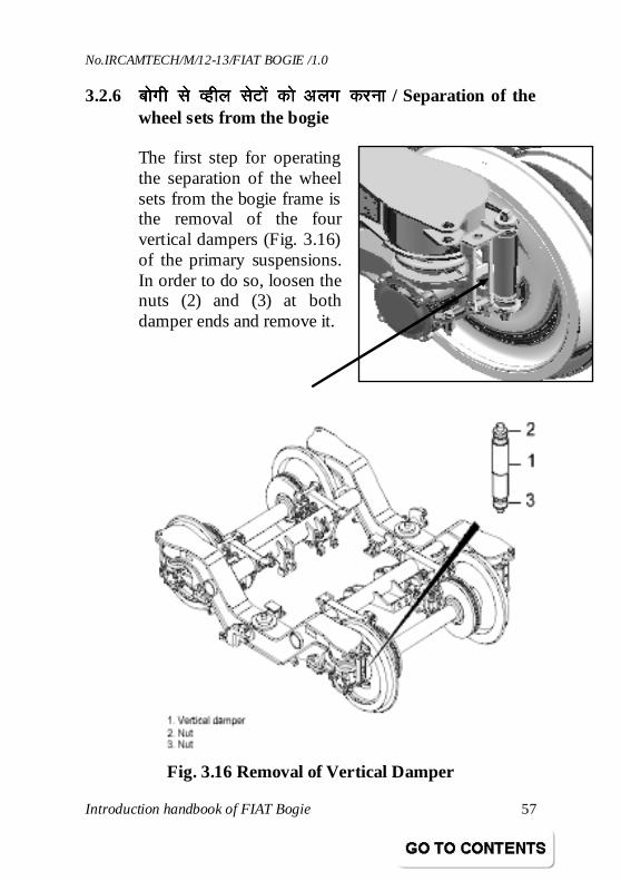
3.2.6 cksxh ls Oghy lsVksa dks vyx djukcksxh ls Oghy lsVksa dks vyx djukcksxh ls Oghy lsVksa dks vyx djukcksxh ls Oghy lsVksa dks vyx djuk / Separation of the wheel sets from the bogie
The first step for operating the separation of the wheel sets from the bogie frame is the removal of the four vertical dampers (Fig. 3.16) of the primary suspensions. In order to do so, loosen the nuts (2) and (3) at both damper ends and remove it.
Fig. 3.16 Removal of Vertical Damper
No.IRCAMTECH/M/12-13/FIAT BOGIE /1.0
Introduction handbook of FIAT Bogie 58
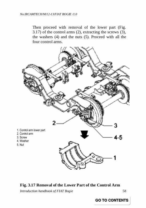
Then proceed with removal of the lower part (Fig. 3.17) of the control arms (2), extracting the screws (3), the washers (4) and the nuts (5). Proceed with all the four control arms.
Fig. 3.17 Removal of the Lower Part of the Control Arm
1. Control arm lower part 2. Control arm
3. Screw 4. Washer
5. Nut
No.IRCAMTECH/M/12-13/FIAT BOGIE /1.0
Introduction handbook of FIAT Bogie 59
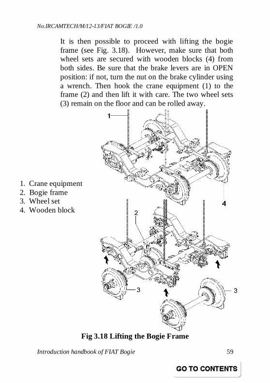
It is then possible to proceed with lifting the bogie frame (see Fig. 3.18). However, make sure that both wheel sets are secured with wooden blocks (4) from both sides. Be sure that the brake levers are in OPEN position: if not, turn the nut on the brake cylinder using a wrench. Then hook the crane equipment (1) to the frame (2) and then lift it with care. The two wheel sets (3) remain on the floor and can be rolled away.
Fig 3.18 Lifting the Bogie Frame
1. Crane equipment 2. Bogie frame 3. Wheel set 4. Wooden block
No.IRCAMTECH/M/12-13/FIAT BOGIE /1.0
Introduction handbook of FIAT Bogie 60
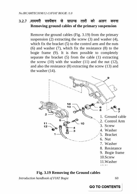
3.2.7 IzkkIzkkIzkkIzkk;ejh lLisa’ku ls xzkmUM rkjksa dks vyx djuk;ejh lLisa’ku ls xzkmUM rkjksa dks vyx djuk;ejh lLisa’ku ls xzkmUM rkjksa dks vyx djuk;ejh lLisa’ku ls xzkmUM rkjksa dks vyx djuk Removing ground cables of the primary suspension
Remove the ground cables (Fig. 3.19) from the primary suspension (2) extracting the screw (3) and washer (4), which fix the bracket (5) to the control arm and the nuts (6) and washer (7), which fix the resistance (8) to the bogie frame (9). It is then possible to completely separate the bracket (5) from the cable (1) extracting the screw (10) with the washer (11) and the nut (12), and also the resistance (8) extracting the screw (13) and the washer (14).
Fig. 3.19 Removing the Ground cables
1. Ground cable 2. Control Arm 3. Screw 4. Washer 5. Bracket 6. Nut 7. Washer 8. Resistance 9. Bogie frame 10.Screw 11.Washer 12.Nut
No.IRCAMTECH/M/12-13/FIAT BOGIE /1.0
Introduction handbook of FIAT Bogie 61
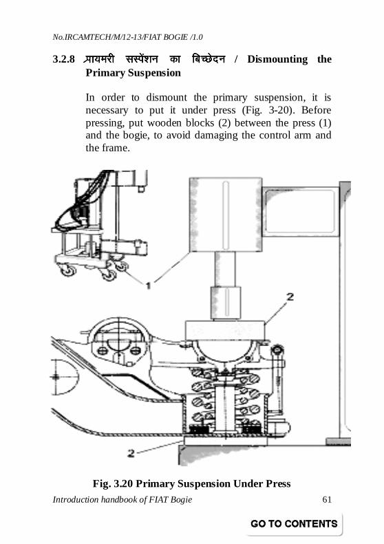
3.2.8 Izkk;ejh lLisa’ku dk fcPNsnuIzkk;ejh lLisa’ku dk fcPNsnuIzkk;ejh lLisa’ku dk fcPNsnuIzkk;ejh lLisa’ku dk fcPNsnu / Dismounting the Primary Suspension
In order to dismount the primary suspension, it is necessary to put it under press (Fig. 3-20). Before pressing, put wooden blocks (2) between the press (1) and the bogie, to avoid damaging the control arm and the frame.
Fig. 3.20 Primary Suspension Under Press
No.IRCAMTECH/M/12-13/FIAT BOGIE /1.0
Introduction handbook of FIAT Bogie 62
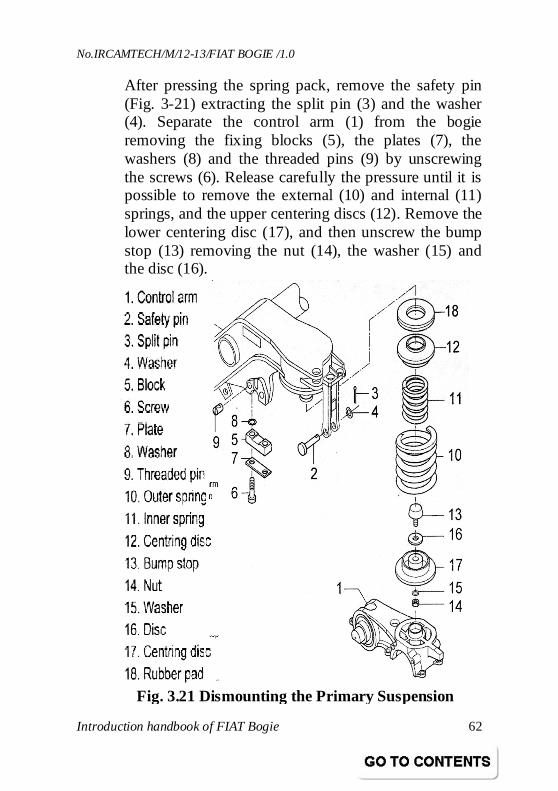
After pressing the spring pack, remove the safety pin (Fig. 3-21) extracting the split pin (3) and the washer (4). Separate the control arm (1) from the bogie removing the fixing blocks (5), the plates (7), the washers (8) and the threaded pins (9) by unscrewing the screws (6). Release carefully the pressure until it is possible to remove the external (10) and internal (11) springs, and the upper centering discs (12). Remove the lower centering disc (17), and then unscrew the bump stop (13) removing the nut (14), the washer (15) and the disc (16).
Fig. 3.21 Dismounting the Primary Suspension
No.IRCAMTECH/M/12-13/FIAT BOGIE /1.0
Introduction handbook of FIAT Bogie 63
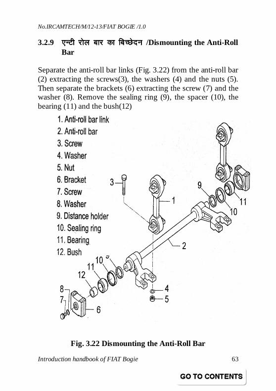
3.2.9 ,UVh jksy ckj dk fcPNsnu ,UVh jksy ckj dk fcPNsnu ,UVh jksy ckj dk fcPNsnu ,UVh jksy ckj dk fcPNsnu /Dismounting the Anti-Roll Bar
Separate the anti-roll bar links (Fig. 3.22) from the anti-roll bar (2) extracting the screws(3), the washers (4) and the nuts (5). Then separate the brackets (6) extracting the screw (7) and the washer (8). Remove the sealing ring (9), the spacer (10), the bearing (11) and the bush(12)
Fig. 3.22 Dismounting the Anti-Roll Bar
No.IRCAMTECH/M/12-13/FIAT BOGIE /1.0
Introduction handbook of FIAT Bogie 64
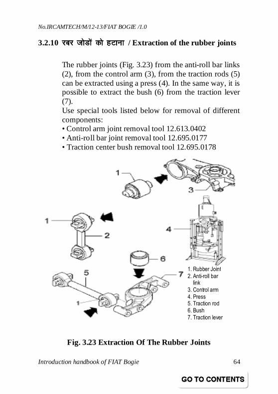
3.2.10 jcj tksMksa dks gVkukjcj tksMksa dks gVkukjcj tksMksa dks gVkukjcj tksMksa dks gVkuk / Extraction of the rubber joints
The rubber joints (Fig. 3.23) from the anti-roll bar links (2), from the control arm (3), from the traction rods (5) can be extracted using a press (4). In the same way, it is possible to extract the bush (6) from the traction lever (7). Use special tools listed below for removal of different components: • Control arm joint removal tool 12.613.0402 • Anti-roll bar joint removal tool 12.695.0177 • Traction center bush removal tool 12.695.0178
Fig. 3.23 Extraction Of The Rubber Joints
1. Rubber Joint
2. Anti-roll bar link
3. Control arm
4. Press 5. Traction rod
6. Bush
7. Traction lever
No.IRCAMTECH/M/12-13/FIAT BOGIE /1.0
Introduction handbook of FIAT Bogie 65
4.0 cksxh vlsEcyhcksxh vlsEcyhcksxh vlsEcyhcksxh vlsEcyh / BOGIE ASSEMBLY 4.1 lkekUlkekUlkekUlkekU; fVIi.kh; fVIi.kh; fVIi.kh; fVIi.kh / General note
Before starting, it is necessary to clean the bogie frame and in particular all the threads and the seats for the bump stops, the dampers, the rubber elements, etc. All rough surfaces and screws must be well greased with AUTOL TOP 2000. • Security plates and split pins can be used only once. • When dismounting screws and other fixings at revision, replace them with new ones.
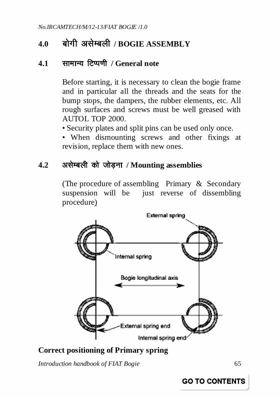
4.2 vlsEcyh dks tksM+ukvlsEcyh dks tksM+ukvlsEcyh dks tksM+ukvlsEcyh dks tksM+uk / Mounting assemblies
(The procedure of assembling Primary & Secondary suspension will be just reverse of dissembling procedure)
Correct positioning of Primary spring
No.IRCAMTECH/M/12-13/FIAT BOGIE /1.0
Introduction handbook of FIAT Bogie 66
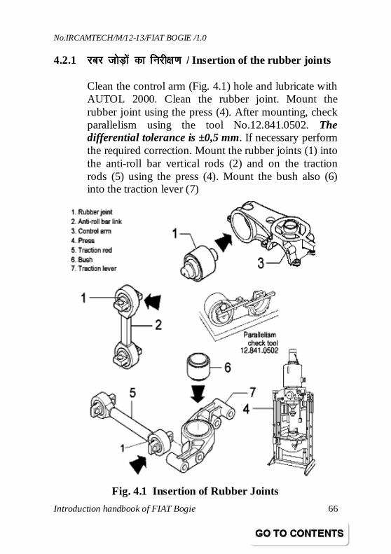
4.2.1 jcj tksM+ksa dk fujh{k.k jcj tksM+ksa dk fujh{k.k jcj tksM+ksa dk fujh{k.k jcj tksM+ksa dk fujh{k.k / Insertion of the rubber joints
Clean the control arm (Fig. 4.1) hole and lubricate with AUTOL 2000. Clean the rubber joint. Mount the rubber joint using the press (4). After mounting, check parallelism using the tool No.12.841.0502. The differential tolerance is ±0,5 mm. If necessary perform the required correction. Mount the rubber joints (1) into the anti-roll bar vertical rods (2) and on the traction rods (5) using the press (4). Mount the bush also (6) into the traction lever (7)
Fig. 4.1 Insertion of Rubber Joints
No.IRCAMTECH/M/12-13/FIAT BOGIE /1.0
Introduction handbook of FIAT Bogie 67
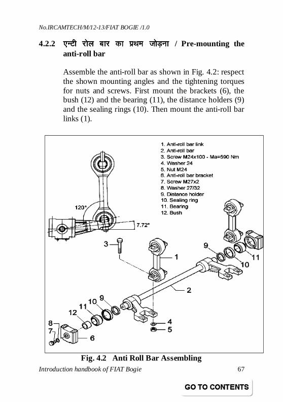
4.2.2 ,UVh jksy ckj dk izFke tksM+uk,UVh jksy ckj dk izFke tksM+uk,UVh jksy ckj dk izFke tksM+uk,UVh jksy ckj dk izFke tksM+uk / Pre-mounting the anti-roll bar
Assemble the anti-roll bar as shown in Fig. 4.2: respect the shown mounting angles and the tightening torques for nuts and screws. First mount the brackets (6), the bush (12) and the bearing (11), the distance holders (9) and the sealing rings (10). Then mount the anti-roll bar links (1).
Fig. 4.2 Anti Roll Bar Assembling
No.IRCAMTECH/M/12-13/FIAT BOGIE /1.0
Introduction handbook of FIAT Bogie 68
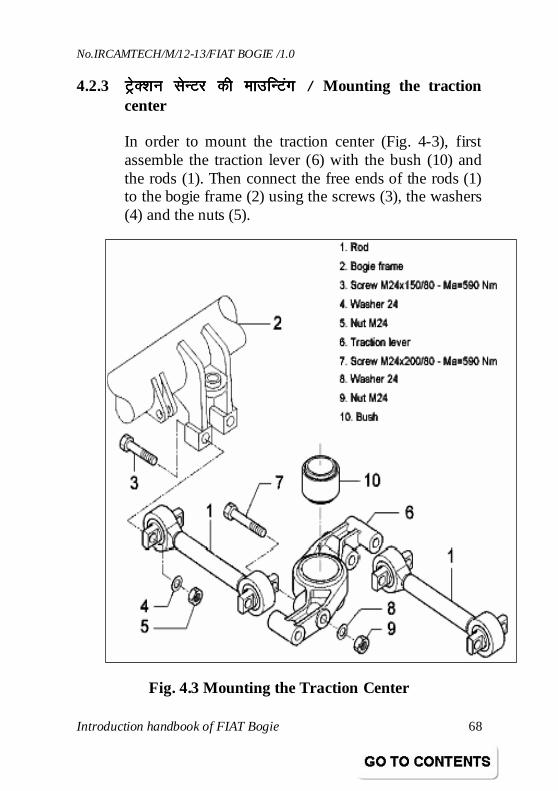
4.2.3 VªsD’ku lsUVj dh ekmfUVaxVªsD’ku lsUVj dh ekmfUVaxVªsD’ku lsUVj dh ekmfUVaxVªsD’ku lsUVj dh ekmfUVax / Mounting the traction center
In order to mount the traction center (Fig. 4-3), first assemble the traction lever (6) with the bush (10) and the rods (1). Then connect the free ends of the rods (1) to the bogie frame (2) using the screws (3), the washers (4) and the nuts (5).
Fig. 4.3 Mounting the Traction Center
No.IRCAMTECH/M/12-13/FIAT BOGIE /1.0
Introduction handbook of FIAT Bogie 69
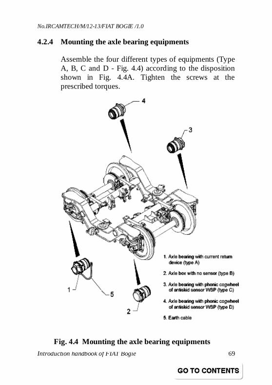
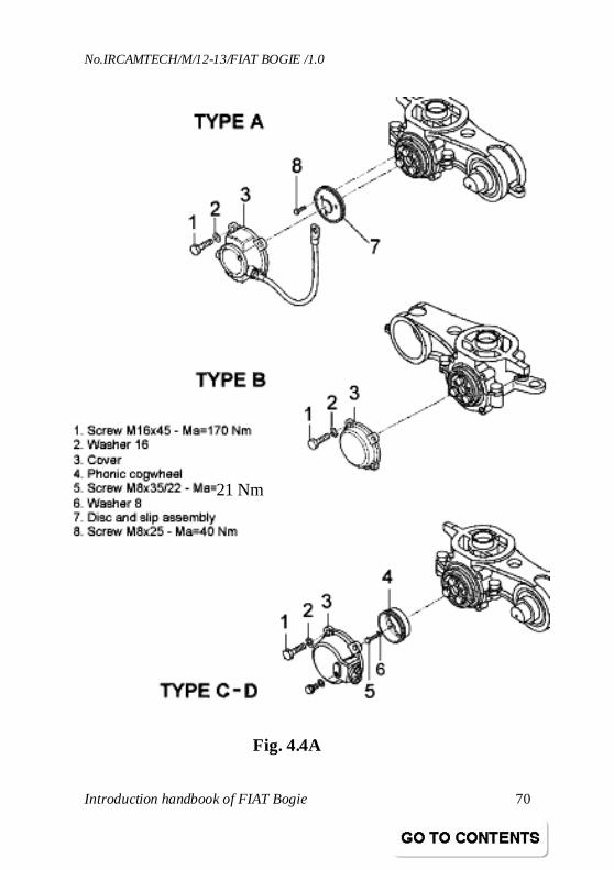
4.2.4 Mounting the axle bearing equipments
Assemble the four different types of equipments (Type A, B, C and D - Fig. 4.4) according to the disposition shown in Fig. 4.4A. Tighten the screws at the prescribed torques.
Fig. 4.4 Mounting the axle bearing equipments
No.IRCAMTECH/M/12-13/FIAT BOGIE /1.0
Introduction handbook of FIAT Bogie 70
Fig. 4.4A
21 Nm
No.IRCAMTECH/M/12-13/FIAT BOGIE /1.0
Introduction handbook of FIAT Bogie 71
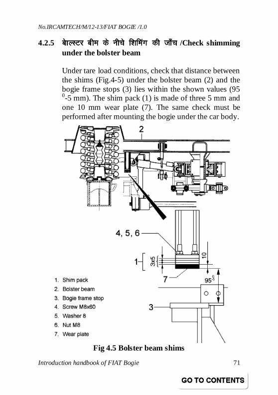
4.2.5 cskYLVj che ds uhps f’kfeax dh tk¡pcskYLVj che ds uhps f’kfeax dh tk¡pcskYLVj che ds uhps f’kfeax dh tk¡pcskYLVj che ds uhps f’kfeax dh tk¡p /Check shimming under the bolster beam
Under tare load conditions, check that distance between the shims (Fig.4-5) under the bolster beam (2) and the bogie frame stops (3) lies within the shown values (95 0-5 mm). The shim pack (1) is made of three 5 mm and one 10 mm wear plate (7). The same check must be performed after mounting the bogie under the car body.
Fig 4.5 Bolster beam shims
No.IRCAMTECH/M/12-13/FIAT BOGIE /1.0
Introduction handbook of FIAT Bogie 72
4.3 LØwM dusD’kuLØwM dusD’kuLØwM dusD’kuLØwM dusD’ku / Screwed connections All the screwed connections used in the bogie design are mounted according to the Tightening torques and are calculated according to a required pre-load and other functional parameters. The torque max dispersion lies within ± 10 %.
4.3.1 VkWdZ dUVªksy dks dluk VkWdZ dUVªksy dks dluk VkWdZ dUVªksy dks dluk VkWdZ dUVªksy dks dluk / Torque controlled tightening
‘Torque controlled tightening’ means the use of dynamometric wrenches provided with an indicator and torque-controlled motors for the tightening. The tool requisites are defined according to DIN 25202 and include the tightening coefficient (preload and applied torque dispersion) and must comply to B Class screwed connections according to DIN 25202
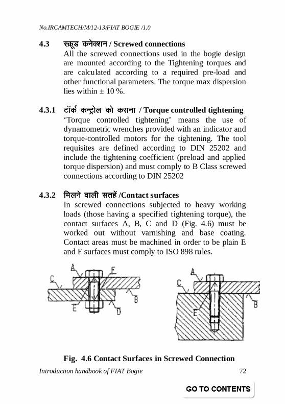
4.3.2 feyus okyh lrgsafeyus okyh lrgsafeyus okyh lrgsafeyus okyh lrgsa /Contact surfaces In screwed connections subjected to heavy working loads (those having a specified tightening torque), the contact surfaces A, B, C and D (Fig. 4.6) must be worked out without varnishing and base coating. Contact areas must be machined in order to be plain E and F surfaces must comply to ISO 898 rules.
Fig. 4.6 Contact Surfaces in Screwed Connection
No.IRCAMTECH/M/12-13/FIAT BOGIE /1.0
Introduction handbook of FIAT Bogie 73
4.4 nzO; Xyw ds lkFk tksM+ksa dh tk¡pnzO; Xyw ds lkFk tksM+ksa dh tk¡pnzO; Xyw ds lkFk tksM+ksa dh tk¡pnzO; Xyw ds lkFk tksM+ksa dh tk¡p / Securing a connection with liquid glue
In order to secure a screwed connection, it is possible to use special glues, which generate a rigid junction (with dismounting possibilities) between the internal and external threads of a screwed connection. Before using such glues, it is necessary that both threads of a connection are clean and Un-greased.
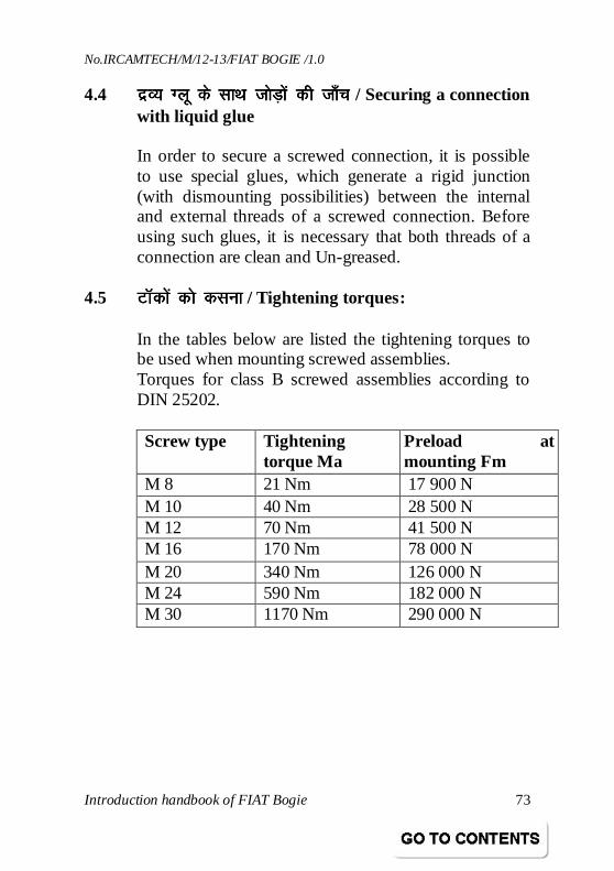
4.5 VkWdksa dks dlukVkWdksa dks dlukVkWdksa dks dlukVkWdksa dks dluk / Tightening torques:
In the tables below are listed the tightening torques to be used when mounting screwed assemblies. Torques for class B screwed assemblies according to DIN 25202. Screw type Tightening
torque Ma Preload at mounting Fm
M 8 21 Nm 17 900 N M 10 40 Nm 28 500 N M 12 70 Nm 41 500 N M 16 170 Nm 78 000 N M 20 340 Nm 126 000 N M 24 590 Nm 182 000 N M 30 1170 Nm 290 000 N
No.IRCAMTECH/M/12-13/FIAT BOGIE /1.0
Introduction handbook of FIAT Bogie 74
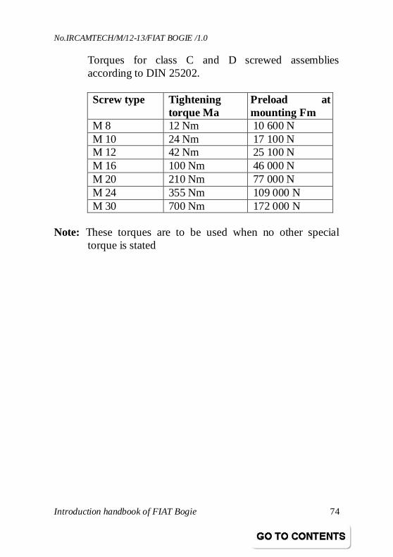
Torques for class C and D screwed assemblies according to DIN 25202. Screw type Tightening
torque Ma Preload at mounting Fm
M 8 12 Nm 10 600 N M 10 24 Nm 17 100 N M 12 42 Nm 25 100 N M 16 100 Nm 46 000 N M 20 210 Nm 77 000 N M 24 355 Nm 109 000 N M 30 700 Nm 172 000 N
Note: These torques are to be used when no other special
torque is stated
No.IRCAMTECH/M/12-13/FIAT BOGIE /1.0
Introduction handbook of FIAT Bogie 75
4.6 fQ,V cskxh ds fy, [kkl ;a=fQ,V cskxh ds fy, [kkl ;a=fQ,V cskxh ds fy, [kkl ;a=fQ,V cskxh ds fy, [kkl ;a= / Special tools for FIAT Bogie
• Press for secondary suspension • Mounting tool for bearing • Dismounting tool for bearing • Anti-roll bar elastic joint mounting tool • Anti-roll bar elastic joint removal tool • Anti-roll bar bearing mounting • Parallelism check tool • Traction center bush mounting • Traction center bush removal • Traction center mounting • Press for axle bearing • Control arm elastic joint mounting • Control arm elastic joint removal • Axle bearing mounting tool • Axle bearing removal tool • Press for MINER springs • Tool for wheel set transportation • Press for primary suspension
No.IRCAMTECH/M/12-13/FIAT BOGIE /1.0
Introduction handbook of FIAT Bogie 76
4.7 fQ,V cksxh ds vksiu ykbu esa j[kj[kko ds fy, funsZ'kfQ,V cksxh ds vksiu ykbu esa j[kj[kko ds fy, funsZ'kfQ,V cksxh ds vksiu ykbu esa j[kj[kko ds fy, funsZ'kfQ,V cksxh ds vksiu ykbu esa j[kj[kko ds fy, funsZ'k Guideline for Open Line Maintenance for Fiat Bogie
The following maintenance schedules are to be carried out.
Coaching Depot Schedule
Schedule D1 : Every Trip/Weekly Schedule D2 : Monthly ± 3 days Schedule D3 : Half Yearly ± 15 days
Schedule D1 (Every Trip/Weekly)
The following items shall be attended during schedule D1. Bogie Frame and Bolster Assembly • Perform a visual check on longitudinal beams,
cross beams & bolster for cracks, damages and corrosion.
• Perform a visual check on brake supports, damper supports, traction centre supports and anti roll bar supports for cracks, damages and corrosion.
• Check bogie bolster sub-assembly and brackets for cracks, damages and corrosion.
Primary & Secondary Suspension • Visually check springs for cracks, damages,
corrosion or foreign objects presence. • Check miner pads for cracks, damages and
ageing. • Visually check safety cables for damages, cracks
and corrosion.
No.IRCAMTECH/M/12-13/FIAT BOGIE /1.0
Introduction handbook of FIAT Bogie 77
Primary/Secondary/Yaw dampers • Perform a visual check on dampers for damage,
cracks and oil leaks. • Perform a visual check on all fixings for
loosening and/or missing components. • Perform a visual check on rubber elements for
cracks and ageing. Bearings • Carry out bearing feeling for detection of hot
bearing. • Check bearings for grease leakage. Wheel & Axle • Perform a visual check on wheels for cracks,
damages and tyre defects. • Check by wheel profile gauge, the wheel flange
thickness and profile. • Check axle for cracks and signs of corrosion, if
any.
Note: Please refer to RDSO CMI – K 003 (Guidelines
for interpretation of wheel defects) and ‘Maintenance Manual for ICF design BG coaches’ for details.
Control Arm • Perform a visual check on all fixings for
loosening and / or missing components. • Visually check control arm parts for damages,
cracks or corrosion marks. • Inspect the rubber joint until it is visible for
cracks, damages and ageing.
No.IRCAMTECH/M/12-13/FIAT BOGIE /1.0
Introduction handbook of FIAT Bogie 78
Anti Roll bar Assembly • Perform a visual check on Anti roll bar, links and
brackets for cracks, damages and corrosion. • Perform a visual check on rubber joints for
cracks, damage and ageing. • Visually inspect for grease oozing out of anti roll
bar bearings, which may result in bearing failure. • Perform visual check on all fixings for
loosening/missing fittings. Traction Centre • Perform a visual check on the traction centre
lever and on the rods for cracks, damages and corrosion.
• The assembly should be free to move, and not blocked by any foreign objects.
• Perform a visual check on all fixings for loosening.
• Perform a visual check on rubber joints for cracks/damages.
Rotation Limiter • Perform a visual check of rotation limiter-
components. Rubber and Rubber/Metal Bonded Parts • Perform a visual check on rubber and
rubber/metal bonded parts for cracks, damages and ageing.
Axle Bearing Instruments • Perform a visual check on all grounding cables &
WSP equipment cables for breaks/ damages.
No.IRCAMTECH/M/12-13/FIAT BOGIE /1.0
Introduction handbook of FIAT Bogie 79
• Visually check equipment for absence of damages, cracks, and corrosion marks.
• Check functioning of WSP equipment. Verify that the signal arrives correctly to the diagnostic equipment.
Schedule D2 (Monthly)
Perform all the items of schedule D1. In addition to this perform the activities- as given below.
Bogie Frame • Wash the bogie frame thoroughly with water jet
in washing line, making sure that water is not directed towards pneumatic / electrical connections and axle bearings.
Axle Bearing Instruments • Inspect the Earthing equipment for wear of slip
assembly / carbon bars. • Monthly / Quarterly inspection of WSP
equipment to be carried out as per schedule given by OEM.
Wheel & Axle • Check treads diameter and wear of wheel profile.
If necessary, perform re-profiling.
Pins and Bushes • Lubricate all pins and bushes.
Schedule D3 (Half Yearly)
Perform all the activities of schedule D2. In addition to this, perform the activities, as given below.
Bogie Frame
No.IRCAMTECH/M/12-13/FIAT BOGIE /1.0
Introduction handbook of FIAT Bogie 80
• Examine the bogie frame for corrosion / damages, especially at critical locations.
• Carry out paint touch up with high built epoxy primer and paint as per RCF specifications MDTS – 166.
Wheel & Axle • Check wheels offset on axle (1600 mm± 1 mm)
Control Arm • Renew protection treatment with Tectyl /Cortec
VC 1368 on the rubber joint on visible areas.
Axle Bearing Instruments • Replace all carban brushes on earthing devices.
;fn vki bl lanHkZ esa dksbZ fopkj vkSj fo’ks"k lq>ko
nsuk pkgrs gksa rks d̀Ik;k gesa bl irs ij fy[ksaA
laidZ lw= % funs’kd ¼;k¡f=d½funs’kd ¼;k¡f=d½funs’kd ¼;k¡f=d½funs’kd ¼;k¡f=d½
Ik=kpkj dk irk % Hkkjrh; jsy mPp vuqj{k.k izkS|ksfxdh dsUnz] egkjktiqj] Xokfy;j e- iz-
fiudksM 474 005 Qksu Qksu Qksu Qksu % 0751&2470803% 0751&2470803% 0751&2470803% 0751&2470803
0751&2470 0751&2470 0751&2470 0751&2470890890890890
QSDl QSDl QSDl QSDl % 0751&2470841 % 0751&2470841 % 0751&2470841 % 0751&2470841
vuqj{k.k izkS|ksfxdh vkSj dk;Ziz.kkyh dks mUu;vuqj{k.k izkS|ksfxdh vkSj dk;Ziz.kkyh dks mUu;vuqj{k.k izkS|ksfxdh vkSj dk;Ziz.kkyh dks mUu;vuqj{k.k izkS|ksfxdh vkSj dk;Ziz.kkyh dks mUu;u djuk u djuk u djuk u djuk rFkk mRikndrk vkSj jsyos dh ifjlEifRr ,oa tu’kfDr rFkk mRikndrk vkSj jsyos dh ifjlEifRr ,oa tu’kfDr rFkk mRikndrk vkSj jsyos dh ifjlEifRr ,oa tu’kfDr rFkk mRikndrk vkSj jsyos dh ifjlEifRr ,oa tu’kfDr ds fu"iknu esa lq/kkj djuk ftlls vUrfoZ"k;ksa esa ds fu"iknu esa lq/kkj djuk ftlls vUrfoZ"k;ksa esa ds fu"iknu esa lq/kkj djuk ftlls vUrfoZ"k;ksa esa ds fu"iknu esa lq/kkj djuk ftlls vUrfoZ"k;ksa esa fo’oluh;rk] mi;ksfxrk vkSj n{krk izkIr dh tk ldsA fo’oluh;rk] mi;ksfxrk vkSj n{krk izkIr dh tk ldsA fo’oluh;rk] mi;ksfxrk vkSj n{krk izkIr dh tk ldsA fo’oluh;rk] mi;ksfxrk vkSj n{krk izkIr dh tk ldsA
gekjk mn~ns’;gekjk mn~ns’;gekjk mn~ns’;gekjk mn~ns’;

If you have any suggestions and any specific comments, please write to us. Contact person : Executive Director Postal address : Indian Railways, Centre for Advanced Maintenance Technology, Maharajpur, Gwalior. Pin code - 474 005 Phone : 0751- 2470803 Fax : 0751- 2470841
Email address : [email protected]
To upgrade maintenance technologies and methodologies and achieve improvement in productivity and performance of all Railway assets and man power which inter-alia would cover reliability, availability, utilisation and efficiency.
OUR OBJECTIVE