
INSTRUCTIONS FOR POOL LOCATION • EXCAVATING • · PDF fileINSTRUCTIONS FOR POOL...
28
INSTRUCTIONS FOR POOL LOCATION • EXCAVATING • GRADING • WALL AND LINER INSTALLATION • BACK-FILLING • DECKS • LIGHTING • STEPS • PLUMBING AND DRAIN TM TM A DIVISION OF INC.
Transcript of INSTRUCTIONS FOR POOL LOCATION • EXCAVATING • · PDF fileINSTRUCTIONS FOR POOL...

INSTRUCTIONS FOR POOL LOCATION • EXCAVATING • GRADING • WALL AND LINERINSTALLATION • BACK-FILLING • DECKS • LIGHTING • STEPS • PLUMBING AND DRAIN
TM
TM
A DIVISION OF
INC.

2
HYDRA POOLS HYDRA POOLS HYDRA POOLS
HYDRA CORNERSTONE PINNACLE
For a copy of
Standards for Residential
Swimming Pools
contact the
APSP
2111 Eisenhower AvenueAlexandria,VA 22314
(703) 838-0083(703) 549-0493

3
HYDRA POOLS HYDRA POOLS HYDRA POOLS
HYDRA CORNERSTONE PINNACLE
GENERAL GUIDELINES
Before you begin, check the pool component list and read the entire installation manual. During the varioussteps of installation, refer to this installation manual, the installation video and the appropriate “dig spec”drawing supplied to you.
Construction Sequence
1. Check with utility company in regards to underground utilities (gas, electric, phone, etc.)
2. Obtain all necessary permits
3. Hire an electrician if needed
4. Arrange for water to be delivered if necessary
5. Arrange for fencing around the pool area and check local codes for requirements
6. Follow this installation manual carefully and complete only the steps that pertain to the Hydra polymerpool you are installing. REMEMBER, Hydra has three polymer pool lines.
Tools Needed for Installation
Adjustable wrenchScrewdriversSocket set25’ and 100’ tape measureUtility knifeExtension chordsString lineDrills and assorted bitsShovels (flat and round)Trowels (mags and finish)Carpenter’s square and levelWheelbarrow3" hole sawHacksaw21/2" hole saw
Large channel-lock pliersBroomTamperSledge hammer/regular hammerHoseDuct tapeTransit (laser level preferred) (rent)RakesMighty Vac or commercial shop vacPick axeCaulk gunCement mixer/plaster mixer (needed for installationof vermiculite bottom—rent if necessary)Marking spray paint (for marking ground)
Heavy Equipment Needed (hire if necessary)
BackhoeBobcatDump truck
Note:A qualified operator is needed for heavy equipment.

4
HYDRA POOLS HYDRA POOLS HYDRA POOLS
HYDRA CORNERSTONE PINNACLE
POOL LOCATION/LAYOUT
Choose your pool’s location very carefully, as a less desirable site can increase your time, cost and effortduring installation. Consider the following when selecting a pool site:
1. Insure the pool is clear of all property lines and variances.
2. Insure a minimum 10' wide opening for access to the pool site by large equipment and concrete trucks.
3. Insure the pool site is clear of all underground pipes, tanks, wires and overhead wires.
4. Level ground is preferred but not required.Water drainage away from all sides of the pool is necessary.
5.The pool site should be in a sunny area with few, if any, trees around the pool.
6.Try to position the long wall with the skimmer facing the prevailing winds.
7. Building on backfill areas is not recommended.

5
HYDRA POOLS HYDRA POOLS HYDRA POOLS
HYDRA CORNERSTONE PINNACLE
INITIAL LAYOUT
Rectangle
All rectangular pools have a two-foot to three-foot overdig (depending on brand of panel) to form a shelf forthe panels. Start by driving four stakes in the ground to make a box two feet to three feet larger than thepool you are installing. For example, a 20' x 40' pool requires a box that measures 24' x 44' or 26' x 46'.Square the box by measuring diagonally from stake to stake, ensuring all measurements are the same (seeFigure 1).
Oval
All oval pools have a two-foot to three-foot overdig to form a shelf for the panels. Start by driving fourstakes in the ground to make a box four feet wider than the pool but only as long as the straight wall. Forexample, an 18' x 36' pool requires a box that measures 22' x 18' (or larger depending on the panel brand).Square the box by measuring diagonally from stake to stake, ensuring all measurements are the same.Tocreate the radius ends of the pool, locate the center point of the 22' width and drive a stake. Holding the endof a tape measure on the stake, move out 11' and paint an arc, connecting the ends of each straight side (seeFigure 2).
44'
24'50' 11/2"
Figure 1: Rectangle Pool Layout
Figure 2: Oval Pool Layout
18'
22'28' 51/8"11'R
Octagon
All octagon pools have a two-foot or three-foot overdig to form a shelf for the panels. Start by driving astake at the center point of the pool. Holding the end of a tape measure on the stake, move out one-half thewidth of the pool, plus two feet for the overdig, and paint a circle around the center stake. For example, a 24'octagon would require a circle 14' from the center stake.

6
HYDRA POOLS HYDRA POOLS HYDRA POOLS
HYDRA CORNERSTONE PINNACLE
SETTING POOL ELEVATION
The top of the panel should be no less than 8" above the existing grade.Twelve inches is suggested to keep all drainage away from the pool (seeFigure 3). Now stretch a string line to each of your layout stakes at thelevel of the top of the pool (see Figure 4). If using a laser level, set theproper benchmark.
EXCAVATION
All dimensions in the Pool Layout and Dig Specification Sheet are finish grades, so your excavation shouldalways be 2" deeper than your Pool Layout and Dig-Dimension drawing.This allows space inside the poolwalls for mason sand or hard bottom materials (vermiculite, etc.)
Panel Shelf
Panels and braces will be assembled, set and leveled on the panel shelf.The panel shelf width will bedetermined by the panel line you are installing. THE SHELF IS DUG 42" DOWN FROM THE STRINGLINE OR FROM YOUR BENCHMARK. This should be undisturbed earth, so use caution when diggingthe shelf. DO NOT OVER DIG!!!! This is also the finish depth of the shallow end.
Figure 3: Pool Elevation
Figure 4: String Level / Pool Layout

7
HYDRA POOLS HYDRA POOLS HYDRA POOLS
HYDRA CORNERSTONE PINNACLE
Shallow End
Excavate the shallow end to 42" below the benchmark. If steps are tobe installed, dig 2' to 3' wider than the step and 4' past your panelshelf (see Figure 5).
Deep End
Once the shallow end is dug, paint a line acrossthe pool to represent the break point.Tounderstand the shape of the deep end on astandard hopper pool, envision the hopper as anupside-down pyramid, whose top has been cutoff (see Figure 6).To achieve this shape, start bydividing the length of the slope by four andmarking four equal sections on the wall of theoverdig. For example, a 14' slope would havefour sections, 3'6" each.Then divide the wallheight by four and mark the side and back wall
into four equal sections. For example, a 4' sidewall would have four 1' sections. Now start excavating thehopper at the break point.As the dig proceeds down the slope, use the marks you have made as boundariesfor the dig. For each mark you pass on the slope, move your dig boundary in and down one mark on thesidewall. Using our earlier example, as the dig moves 3'6" down the slope, the dig boundary on each sidewould move in 1' from each sidewall toward the center of the pool, and 1' deeper.The backhoe operatorshould continue this process, tapering all sides, until the end of the slope is reached. Now, continue with thesame dig boundary for the length of the hopper.The back wall should be tapered to the same slope as thesidewalls at the hopper. Caution your operator to work slowly and accurately, and monitor the diggingprocess closely. DO NOT OVER DIG OR UNDER DIG.
Figure 5: Shallow End
Figure 6: Shallow End

8
HYDRA POOLS HYDRA POOLS HYDRA POOLS
HYDRA CORNERSTONE PINNACLE
GROUND-WATER CONDITIONS
Ground water is the term used for the water table. If you should encounter ground water while digging thehopper, don’t panic. Just follow these simple recommendations:
1. Over-dig just the bottom of the hopper by 1' to 2'.
2. Use pea-sized rock to bring the hopper back to grade.
3. Set a foot valve in the pea stone and plumb it to outside of the pool.
4. Run a plumbing line from the hopper to near the filter (see Figure 7).
5. Hook the foot valve to a pump and keep the pump running continuously until the liner has beendropped and the pool is full of water.
6.When installation is complete, cap the plumbing line, leaving it available for use in the future, should theliner need to be replaced.
PANEL INSTALLATION
Start by laying out all panels on the panel shelf. Position a brace and 4 or 5 bolts (depending on the brand ofpanel) at every panel joint, as indicated in the Pool Layout and Dig Dimension Drawing supplied to you.
Starting in the appropriate place for the shape of the pool being built (see below), fasten panels and bracestogether, using non-corrosive nylon bolts.Align the panel joints for a tight fit and hand-tighten (snug) the non-corrosive bolts. DO NOT OVER TIGHTEN!!
Panels are available with pre-cut holes for most commonly used skimmers. Position the skimmer panelaccording to the following guidelines:
1.The skimmer should always be placed on the long wall of the pool, with the prevailing winds blowinginto the skimmer.
2. If you are building a hopper pool, locate the skimmer as per supplied drawing.
3. Insure the skimmer panel will be clear of the wall-mounted safety-rope anchors.
4. Locate returns on walls opposite the skimmer, to push surface debris towards the skimmer.
5. For Aqua Genie Skimmers, see the Aqua Genie manual.
Figure 7: Ground Water Solution

9
HYDRA POOLS HYDRA POOLS HYDRA POOLS
HYDRA CORNERSTONE PINNACLE
Starting Point – Rectangular Pools
Begin in a shallow-end corner. In 4' radius pools, start by bolting the two corner panels together, with a braceoffset from panel joint.Then connect the corner panel assembly to an end-wall straight panel, with a braceoffset from flanges (see Figure 8). Continue to assemble panels and braces according to the Pool Layout andDig Dimension Drawing. If steps are present, determine their location before starting panel assembly andcomplete the step-installation process (see below) when you reach their position.
Starting Point – Oval Pools
Begin at a straight sidewall and bolt the straight panels andbraces together. Repeat this process for the other straightsidewall. Square both sidewalls by measuring diagonallyacross the pool at both the top and the bottom of thepanels. Drive stakes a few inches into the ground at theends of the straight sections to hold them in place. Beginto assemble the radius ends. Bolt the first curved panel and brace to the end of a straight sidewall. Ifrequired, use 5° wedges (see Figure 9) to adjust the radius, as indicated in the Pool Layout and DigDimension Drawing. Continue to assemble panels and braces according to the Pool Layout and DigDimension Drawing. If steps are present, determine their location before starting panel assembly andcomplete the step-installation process (see below) when you reach their position. Insure the radius is true bydriving a stake halfway between the sidewalls, stretching a tape measure from the stake to the radius panels,and checking the distance at various points on the curve.All measurements should be the same. If not, slightlyshift the curved panels until a constant radius is achieved.
Figure 8: Panel / Brace Assembly
Figure 9: 5º Wedge Installation

10
HYDRA POOLS HYDRA POOLS HYDRA POOLS
HYDRA CORNERSTONE PINNACLE
SWEETWATER STEP AND SWIM OUT INSTALLATION
Steps and swim outs are installed in the same manner. Start by setting the step in the excavated areaaccording to the Pool Layout and Dig Dimension Drawing. Use supplied step support system.With the stepin place, clamp the neighboring pool panel to the step, insuring that the face of the step is flush with the paneland that the top of the panel is flush with the bottom of the step coping-receptor nose.
With the panel and step clamped tightly together, drill 3/8" holes through the panel holes into the step flange.Use stainless-steel bolts to secure the panels/braces to the step.
INSTALLING ALUMINUM
COPING
Two types of coping are provided with your Hydrapool system: alignment and pre-shaped. Start byinstalling all pre-shaped coping.This includes 6", 2', 4',and 9' radius, Roman End, 45°, Lazy-Ell and True-Ellcoping. Start by positioning the pre-shaped coping onthe appropriate panels, insuring that the coping lip fitssnugly against the face of the panel. Using the self-tapping screws provided, secure the pre-shaped copingto the panels, starting at the ends of each piece ofcoping and continuing every 12" along the length of thecoping. Next, install the alignment coping onto the panels, leaving a 3/8" gap between pieces for expansion.Secure the straight coping to the panels using the self-tapping screws provided.When installing the alignmentcoping, insure that the coping joints do not line up with any of the panel joints, except at the junction ofalignment and pre-shaped coping. Finally, snap the coping clips over all coping joints.
Figure 10: Coping Installation
11
HYDRA POOLS HYDRA POOLS HYDRA POOLS
HYDRA CORNERSTONE PINNACLE
FINAL CHECK—ALL POOLS
Once all panels, braces and steps have been bolted together and the coping has been secured to the panels, itis time for one final check.A few extra minutes spent verifying the shape of the pool at this stage ofcompletion will lead to a proper liner fit and, ultimately, a job well done.
1. Check diagonal measurements across the pool, at both the top and bottom of the panels, and verifythat they are the same.
2. Level all panels, using patio block or bricks at the panel joints, so that the top of the panel is level withthe benchmark set at the start of construction.
3. Check all panels for vertical alignment using a carpenter’s level on the face of the panel.
4. Check all straight walls for horizontal alignment.To do this, stretch a string the entire length of eachstraight wall, at the top of the panels, insuring that each panel lines up with the string.
STAKE AND SECURE THE POOL
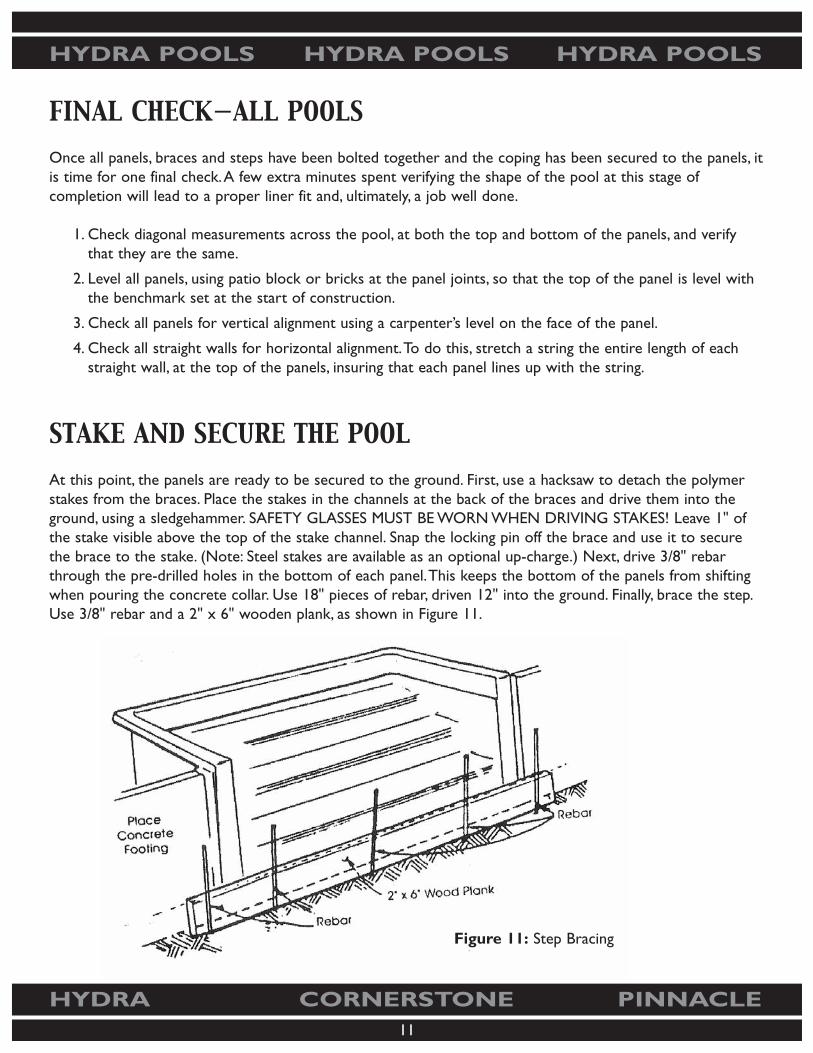
At this point, the panels are ready to be secured to the ground. First, use a hacksaw to detach the polymerstakes from the braces. Place the stakes in the channels at the back of the braces and drive them into theground, using a sledgehammer. SAFETY GLASSES MUST BE WORN WHEN DRIVING STAKES! Leave 1" ofthe stake visible above the top of the stake channel. Snap the locking pin off the brace and use it to securethe brace to the stake. (Note: Steel stakes are available as an optional up-charge.) Next, drive 3/8" rebarthrough the pre-drilled holes in the bottom of each panel.This keeps the bottom of the panels from shiftingwhen pouring the concrete collar. Use 18" pieces of rebar, driven 12" into the ground. Finally, brace the step.Use 3/8" rebar and a 2" x 6" wooden plank, as shown in Figure 11.
Figure 11: Step Bracing
12
HYDRA POOLS HYDRA POOLS HYDRA POOLS
HYDRA CORNERSTONE PINNACLE
PLUMBING
Main Drains
(must be done before bond beam is installed)
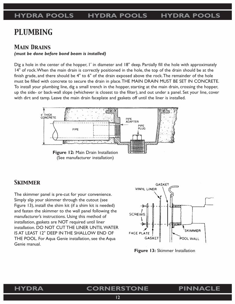
Dig a hole in the center of the hopper, 1' in diameter and 18" deep. Partially fill the hole with approximately14" of rock.When the main drain is correctly positioned in the hole, the top of the drain should be at thefinish grade, and there should be 4" to 6" of the drain exposed above the rock.The remainder of the holemust be filled with concrete to secure the drain in place.THE MAIN DRAIN MUST BE SET IN CONCRETE.To install your plumbing line, dig a small trench in the hopper, starting at the main drain, crossing the hopper,up the side- or back-wall slope (whichever is closest to the filter), and out under a panel. Set your line, coverwith dirt and tamp. Leave the main drain faceplate and gaskets off until the liner is installed.
Skimmer
The skimmer panel is pre-cut for your convenience.Simply slip your skimmer through the cutout (seeFigure 13), install the shim kit (if a shim kit is needed)and fasten the skimmer to the wall panel following themanufacturer’s instructions. Using this method ofinstallation, gaskets are NOT required until linerinstallation. DO NOT CUT THE LINER UNTIL WATERIS AT LEAST 12" DEEP IN THE SHALLOW END OFTHE POOL. For Aqua Genie installation, see the AquaGenie manual.
Figure 12: Main Drain Installation(See manufacturer installation)
Figure 13: Skimmer Installation

13
HYDRA POOLS HYDRA POOLS HYDRA POOLS
HYDRA CORNERSTONE PINNACLE
Return Fittings
Return fittings can be located on any wall, as long as they produce a circular flow pattern (counter clockwisedirection) on the surface of the water, toward the skimmer. Drill a 3" hole in the panel, 12" to 14" down fromthe top of the panel (NOT to the top of the coping). Drill from the back to eliminate hitting the crossbracing on the panels. Slide the return fitting through the hole inside of the pool and install the locknut.Tighten snugly. Leave the fitting faceplate off until the liner has been installed and the water is at least 12"deep in the shallow end of the pool.
CONCRETE BOND BEAM (COLLAR)
When the main-drain plumbing line is run, you are ready to pour the concrete collar around the pool. Makesure there are no gaps under the panels or step. If there are, tamp dirt to fill the opening. Now stretch astring line down the length of each straight wall at the back edge of the coping and insure all panels are flushwith the string. Next, begin pouring your concrete collar.The concrete should be poured 6” to 8” thick.CHECK WITH YOUR LOCAL BUILDING/ZONING OFFICE FOR APPLICABLE CODES. Pourconcrete SLOWLY to prevent forcing the walls out of alignment.After the concrete is poured, recheck allpanels for the proper panel alignment, using a string.When pouring concrete under the step, insure that theconcrete touches the underside of the first tread for proper support.You may need to build a form to insurethere is enough concrete to support the bottom step.
Figure 14: Return Installation
Figure 15: Concrete Collar

14
HYDRA POOLS HYDRA POOLS HYDRA POOLS
HYDRA CORNERSTONE PINNACLE
GRADING THE POOL BOTTOM FOR SAND AND CEMENT
The pool must be graded 2" below the finish dimensions in the Panel Layout and Dig Dimension Drawing.This will be finished with a 2" layer of MASON sand and cement (in a 5-to-1 ratio) or a suitable pool basematerial (vermiculite, etc.).
Locate the sides of the hopper pad by stretching parallel stringsfrom the break point to the end wall.At the same time, locatethe front and back of the hopper pad by stretching stringsbetween the sidewalls of the pool.
Find the finish grade by dropping a plumb bob at the intersectionof the strings to the depth shown on your Dig DimensionDrawing. Drive a stake into each corner of the hopper beneaththe plumb line and string a level line between stakes at therequired depth to indicate the exact position and finish grade ofthe hopper.
Once you have located the hopper pad, use stakes and strings inthe same manner to mark the finish grade of the hopper walls, asshown on your Dig Dimension Drawing.
In each corner of the shallow end, measure the required depthfrom the top of the panels to the pool bottom and place amarker. String a level line between markers to indicate the finishgrade of the bottom.
GG
G1/2
K1/2 K
K
1/2
1/2
STRING
BREAKPOINT
STRING
HOPPER STAKES AT INTERSECTION OF STRINGS
SHALLOWEND

15
HYDRA POOLS HYDRA POOLS HYDRA POOLS
HYDRA CORNERSTONE PINNACLE
PLACEMENT OF SAND/CEMENT MIXTURE
To save effort when adding the sand/cement or vermiculite/cement mixture, dump it near the area to betroweled.A certain amount will roll down.The balance will be easy to rake down. Particular care should betaken with the troweling of the sand/cement bottom.The smoothness and evenness of the bottom willdetermine the appearance of the liner when it is placed in the pool. (There must be NO exposed aggregate.)
In order to get maximum compaction and surface smoothness, thoroughly washed, mason sand (DO NOTUSE RIVER SAND) should be mixed with cement in a 5-to-1 (sand-to-cement) ratio.This will allow thefinishing operation to proceed smoothly. Inspect the sand finish for sharp, oversized aggregate.
NOTE: If optional vermiculite is used, follow manufacturer’s instructions.Sand/cement: Mix in a mixer.It must be moist enough to form a ball in your hand.
How Much Sand And Cement?
The correct sand-to-cement ratio is 5-to-1.The example below should help.
1. Calculate the surface area of the pool. (Example: 20' x 40' = 800 square feet)
2. Multiply by 15% (.15). (Example: 120)
3.Add lines 1 and 2 to arrive at the area to be covered by sand/cement. (Example: 800 + 120 = 920square feet)
4. Divide line 3 by 162.This will tell you how many cubic yards of sand you’ll need.A cubic yard of sand isequal to one ton in weight. Some suppliers will sell by the cubic yard and some will sell by the ton.(Example: 920 ÷ 162 = 5.7 cubic yards, or 11,400 pounds)
5. Divide the pounds of sand by 5 to arrive at the 5-to-1 ratio.This will determine how much cement youneed. (Example: 11,400 ÷ 5 = 2,280 pounds)
6. Divide line 5 by 94 pounds. Most bags of cement are 94 pounds type II (2) Portland cement.This willtell you how many bags of cement you’ll need. (Example: 2,280 ÷ 94 = 24.3 bags)
NOTE:Always order a few extra bags of cement. Return what you do not use. If you have any extrasand, use it in plumbing trenches.
When the finish grade has been established, remove atleast 2" of earth from below the strings.Tamp the entirearea thoroughly and take away all stones, twigs and rocks.
Starting in the hopper end, bring the pool bottomup to finish grade with a damp-sand/cement mixture,or vermiculite/cement mixture.Trowel smooth.

16
HYDRA POOLS HYDRA POOLS HYDRA POOLS
HYDRA CORNERSTONE PINNACLE
VINYL LINER INSTALLATION
General Information
Vinyl liners should be stored in areas with temperatures above 50˚F to prevent excessive shrinkage andpermanent folds in the vinyl.
Cold Weather Installation
When installing a liner in temperature of 65˚F or lower, store the liner at 70˚F to 80˚F for at least 72 hoursprior to installation.When the bottom is finished, bring out the liner and drop it as quickly as possible.Try todrop the liner in direct sunlight to help seat it properly. Do not leave a boxed liner exposed to the elements.
Tools Needed For Liner Installation
Commercial vacuum(s) (Mighty Vac recommended) Garden hoseScrewdrivers, Phillips and straight BroomRazor knife Two to four people
Liner Installation
Vinyl liner installation can be fast and easy; just follow these guidelines!
1. Before you begin installing the liner, insure that the pool bottom is free of any stones, sticks andfootprints.Vacuum with shop-vac thoroughly.
2. Use duct tape to tape all panel joints.
3. Use caulk to secure gaskets to the main drain and skimmer.
4. Insure liner track is clean and free of any sand, concrete, etc.
5. If steps are used, refer to the STEP section beforecontinuing with liner installation.
6. Remove the liner from the box. Place the liner in thedeep end of the pool, with arrows facing the shallowend. Carefully unfold the liner. Have two people take theshallow-end corners and pull the liner to the shallowend (see Figure 22), keeping the liner away from anysharp edges. AVOID DRAGGING THE LINERACROSS THE POOL BOTTOM.
Figure 22: Liner Unfolding
17
HYDRA POOLS HYDRA POOLS HYDRA POOLS
HYDRA CORNERSTONE PINNACLE
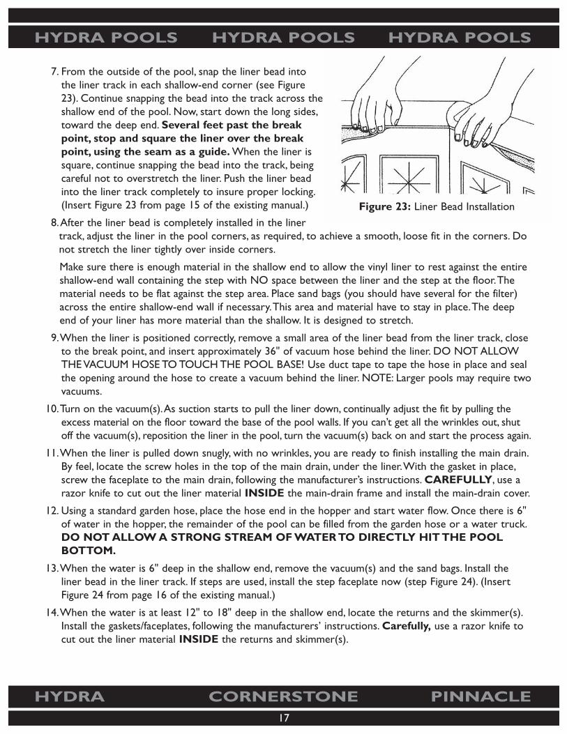
7. From the outside of the pool, snap the liner bead intothe liner track in each shallow-end corner (see Figure23). Continue snapping the bead into the track across theshallow end of the pool. Now, start down the long sides,toward the deep end. Several feet past the breakpoint, stop and square the liner over the breakpoint, using the seam as a guide. When the liner issquare, continue snapping the bead into the track, beingcareful not to overstretch the liner. Push the liner beadinto the liner track completely to insure proper locking.(Insert Figure 23 from page 15 of the existing manual.)
8.After the liner bead is completely installed in the linertrack, adjust the liner in the pool corners, as required, to achieve a smooth, loose fit in the corners. Donot stretch the liner tightly over inside corners.
Make sure there is enough material in the shallow end to allow the vinyl liner to rest against the entireshallow-end wall containing the step with NO space between the liner and the step at the floor.Thematerial needs to be flat against the step area. Place sand bags (you should have several for the filter)across the entire shallow-end wall if necessary.This area and material have to stay in place.The deepend of your liner has more material than the shallow. It is designed to stretch.
9.When the liner is positioned correctly, remove a small area of the liner bead from the liner track, closeto the break point, and insert approximately 36" of vacuum hose behind the liner. DO NOT ALLOWTHE VACUUM HOSE TO TOUCH THE POOL BASE! Use duct tape to tape the hose in place and sealthe opening around the hose to create a vacuum behind the liner. NOTE: Larger pools may require twovacuums.
10.Turn on the vacuum(s).As suction starts to pull the liner down, continually adjust the fit by pulling theexcess material on the floor toward the base of the pool walls. If you can’t get all the wrinkles out, shutoff the vacuum(s), reposition the liner in the pool, turn the vacuum(s) back on and start the process again.
11.When the liner is pulled down snugly, with no wrinkles, you are ready to finish installing the main drain.By feel, locate the screw holes in the top of the main drain, under the liner.With the gasket in place,screw the faceplate to the main drain, following the manufacturer’s instructions. CAREFULLY, use arazor knife to cut out the liner material INSIDE the main-drain frame and install the main-drain cover.
12. Using a standard garden hose, place the hose end in the hopper and start water flow. Once there is 6"of water in the hopper, the remainder of the pool can be filled from the garden hose or a water truck.DO NOT ALLOW A STRONG STREAM OF WATER TO DIRECTLY HIT THE POOLBOTTOM.
13.When the water is 6" deep in the shallow end, remove the vacuum(s) and the sand bags. Install theliner bead in the liner track. If steps are used, install the step faceplate now (step Figure 24). (InsertFigure 24 from page 16 of the existing manual.)
14.When the water is at least 12" to 18" deep in the shallow end, locate the returns and the skimmer(s).Install the gaskets/faceplates, following the manufacturers’ instructions. Carefully, use a razor knife tocut out the liner material INSIDE the returns and skimmer(s).
Figure 23: Liner Bead Installation
18
HYDRA POOLS HYDRA POOLS HYDRA POOLS
HYDRA CORNERSTONE PINNACLE
15. DO NOT REMOVE THE VACUUM(S) WITH LESS THAN 6” OF WATER IN THE SHALLOW ENDAND DO NOT ALLOW THE VACUUM(S) TO RUN WITH MORE THAN 12" OF WATER IN THESHALLOW END. IF THE VACUUM(S) ARE SHUT OFF FOR ANY REASON BEFORE THE WATER IS 6"DEEP IN THE SHALLOW END,THE WATER MUST ALSO BE SHUT OFF UNTIL THE VACUUM ISRESTORED.
SWEETWATER STEP AND SWIM-OUT LINER INSTALLATION
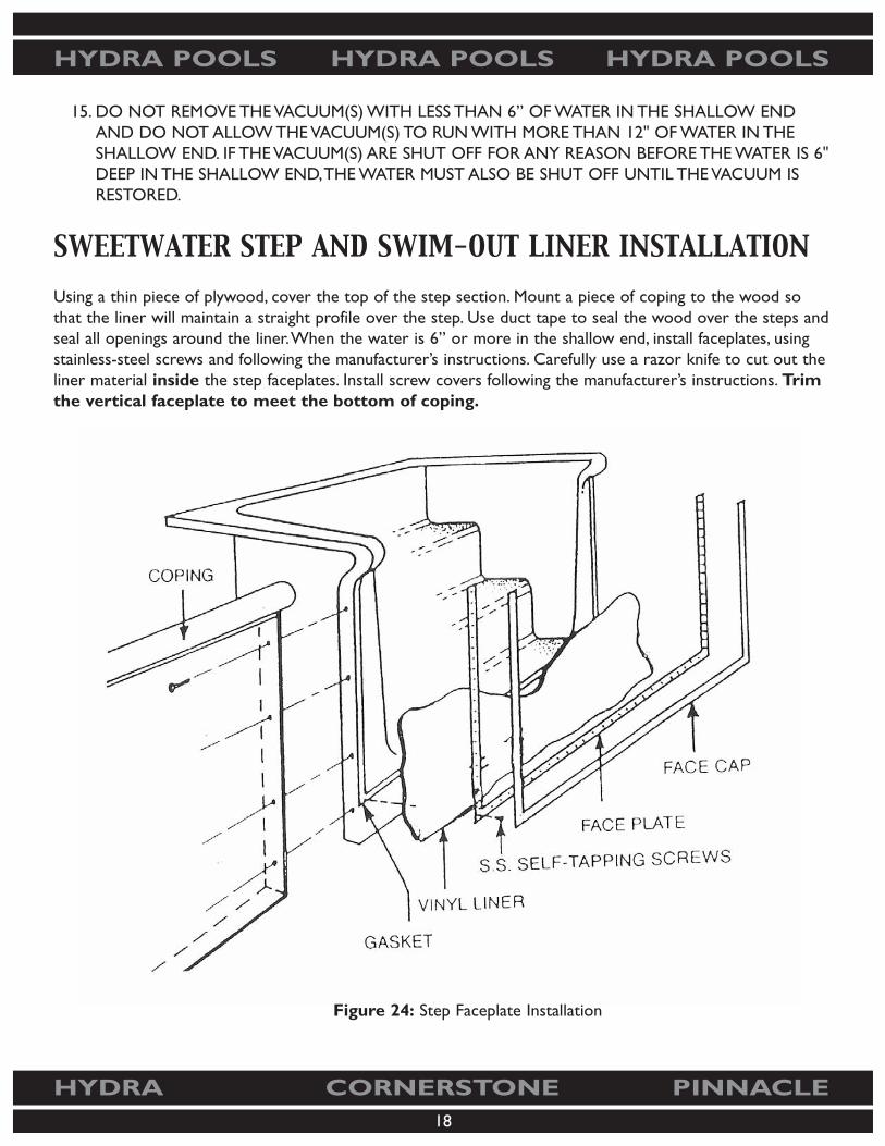
Using a thin piece of plywood, cover the top of the step section. Mount a piece of coping to the wood sothat the liner will maintain a straight profile over the step. Use duct tape to seal the wood over the steps andseal all openings around the liner.When the water is 6” or more in the shallow end, install faceplates, usingstainless-steel screws and following the manufacturer’s instructions. Carefully use a razor knife to cut out theliner material inside the step faceplates. Install screw covers following the manufacturer’s instructions. Trimthe vertical faceplate to meet the bottom of coping.
Figure 24: Step Faceplate Installation

19
HYDRA POOLS HYDRA POOLS HYDRA POOLS
HYDRA CORNERSTONE PINNACLE
BACKFILLING YOUR HYDRA POOL
There are several methods used in backfilling the pool. One method is to backfill as the pool is being filledwith water, keeping the water level even with the backfill material.The backfill material should be placed inlayers and kept even all around the pool. USE ONLY NON-EXPANSIVE MATERIALS FORBACKFILL (SAND, CRUSHED STONE, ETC.). DO NOT USE CLAY, DIRT, SOIL, OR OTHEREARTHEN MATERIALS FOR BACKFILL. Bring the backfill grade to the top of the braces, leaving thebrace top exposed.
INSTALLING CONCRETE DECK
1. Insure the tops of the braces are exposed so the concrete can bond to the brace.
2. Insure the coping clips are installed over the coping joints. Use duct tape to completely cover the faceof all coping, protecting it from splashing concrete.
3. Concrete should be reinforced with either wire-mesh or a fiber-mesh additive (available from mostconcrete companies).
4. Concrete should be a minimum of 6" thick at the pool edge and taper down to 3_" on the outer edge.
5. For proper drainage, the slope must fall 3/4" for every 3' of width.
6. Install ladder/handrail anchors, as required, when forming deck. Follow the manufacturer’s instructions.
7. Insure concrete completely fills the coping.
8. Insure concrete completely fills the gap under the lip of the step to provide additional structuralsupport.
9. Broom-finish the concrete for a non-slip surface or apply other concrete toppings, such as cool deck.
10. Edge and groove the expansion joints or use expansion-joint material. Do not position expansion jointsdirectly over the pool wall braces.
11. Use additional support (piers) down to undisturbed earth when the deck extends more than 4' fromthe pool wall.
12. Pour the deck at least 8' wide where the diving board is installed.
SAFETY ROPE
Use the APSP Guidelines to determine the correct position for the safety rope. Install coping-mounted ropeeyes in this position and fasten the safety rope, following the manufacturer’s instructions.
20
HYDRA POOLS HYDRA POOLS HYDRA POOLS
HYDRA CORNERSTONE PINNACLE
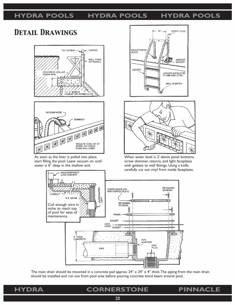
Detail Drawings
As soon as the liner is pulled into place,start filling the pool. Leave vacuum on untilwater is 6" deep in the shallow end.
Coil enough wire inniche to reach topof pool for ease ofmaintenance.
When water level is 2' above panel bottoms,screw skimmer, returns, and light faceplateswith gaskets to wall fittings. Using a knife,carefully cut out vinyl from inside faceplates.
The main drain should be mounted in a concrete pad approx. 24" x 24" x 4" thick.The piping from the main drainshould be installed and run out from pool area before pouring concrete bond beam around pool.

21
HYDRA POOLS HYDRA POOLS HYDRA POOLS
HYDRA CORNERSTONE PINNACLE
Pool Plumbing Schematic
Note:All pool plumbing will be run on top ofretaining collar where possible.
NOTES:
• Polystyrene is not designed to be exposed to UV rays for a longperiod of time. Panels should be covered (back-filled) within a one-to two-week period from excavation.
• All plumbing lines should be installed at ground level (in overdigarea) to eliminate stress from back-fill. Do not hang plumbing.
• Valve all suction and return lines independently.

22
HYDRA POOLS HYDRA POOLS HYDRA POOLS
HYDRA CORNERSTONE PINNACLE

23
HYDRA POOLS HYDRA POOLS HYDRA POOLS
HYDRA CORNERSTONE PINNACLE
FREQUENTLY ASKED QUESTIONS
Excavation Questions
Q. How deep should I excavate the shelf/shallow end of the pool?
A. Once you establish the pool elevation/benchmark, excavate 42" down, which is the height of theHydra, Pinnacle, or Cornerstone polymer panel without the coping attached.This is the depth of theshelf around the entire pool where the panels will sit.This shelf is the same in the shallow end as wellas the deep end.The entire shallow end should be excavated to the same depth as the shelf.You willconstantly be using two terms, dig dimensions and finish dimensions. Be sure you understand bothterms and how to move between them during the construction of your pool.
Q. How deep should the hopper in the deep end be excavated?
A. Always dig the hopper in the deep end 2" deeper than the pool’s finish depth. Example: If the finishdepth of deep end is 8', dig hopper area to a depth of 8'2" from the benchmark or the top of the 42"panel without coping installed.This will allow for the installation of 2" of bottom material, such asvermiculite (pool base) or sand-and-cement mixture in the bottom of the hopper.
Q. Will excavating the shelf area around the pool leave enough room for the braces?
A. The panel line you have will dictate the brace size and the amount of overdig in the shelf area.Requirements are as follows: Hydra requires a 24" overdig, Cornerstone requires a 30" overdig andPinnacle requires a 36" overdig.These are minimum requirements to allow room for the brace and towork in the shelf area.
Q. The installation manual advises not to over dig, what does this mean?
A. Extreme care should be taken when digging any depth or slope of the pool, especially in the hopper ordeep end of the pool. Carefully mark the shelf area where the walls will sit using marking paint orstrings with pins. Do not let the excavator dig past your marks or strings.You may want to handshovel (trim) during this procedure to keep the excavator away from the shelf, thus keeping the shelfedge intact where the walls will sit. Keep in mind that all walls in the hopper area slope at variousangles, thus the term “hopper bottom”.
Q. When digging and encountering ground water, what are some options?
A. The most common option is to use a self-priming pool pump like the one for your pool package.Allplumbing should be schedule 40 PVC installed as shown in the installation manual. Cap the pipe anddrill as many 3/8" holes as possible in the tailpiece buried in the gravel/rock below grade. Make sure allplumbing joints are tight so you can pump the maximum amount of ground water from beneath thepool during the construction of the pool.

24
HYDRA POOLS HYDRA POOLS HYDRA POOLS
HYDRA CORNERSTONE PINNACLE
Finish-Dimensions Questions
Q. What do finish dimensions refer to?
A. Finish dimensions refer to several areas of the pool. Most of the time they refer to the interior of thepool, both length and width, as well as depth measurements. Example:A 16' x 32' rectangle pool that is40" finish in the shallow end and 8’ finish in the deep end would measure 16' wide and 32' long on theinterior of the pool walls.The depth of the pool would be measured from the top of the wall (withoutcoping attached) to the finish bottom material.The bottom material comes 2" up the wall panels tothe finish grade following the entire inside perimeter of the pool.
Q. What standard dimensions are on the drawing you receive with your group?
A. All dimensions on your drawing are finish dimensions, with the exception of the panel-shelf detail.Remember to add 2" to all depth dimensions to allow for the 2" of bottom material needed later.Thisapplies to the panel shelf as well.The panels are 42" high, and the finish inside the pool is 40", up 2" onthe panel.All depth measurements are from the top of the panel with no coping installed.
Panel-Installation Questions
Q. How tight should the panel bolts be?
A. All panel lines need to have the bolts tight and secure. Do not over tighten. One of the panel lines(Hydra) has side flanges that are smooth and require fine-tuning to line up the face and top from onepanel to the next.Two of the panel lines (Cornerstone and Pinnacle) have stud/socket alignment onthe side flanges of every panel.This allows for instant panel alignment and lateral strength.
Q. How level should the panels be?
A. As with any construction project involving walls and footing, the walls need to be level, square andplumb (perfectly vertical) before the footer/collar is poured.After the panels are bolted together, theyneed to be leveled by using the transit to level all panels to every other panel.While this step isprogressing, continue to square the pool also.After the pool panels are level and square, make surethey are plumb.After this is complete, and after the braces are all set, it is time for the collar to bepoured.
Q. How do I bolt the panels to the step, in-wall ladder, cozy cove spa or swim out?
A. After leveling the step following the manufacturer’s instructions, clamp the wall panel to the steps sothat the flanges on the side of the step align with the top and face of the panel. If wall stiffeners are inyour way, mark all holes with a marker, remove step from panels and drill holes where marked on stepflanges. Remember, two panel lines have an alignment feature on one side that must be removed at thistime so the steps will bolt up flush to the panel.The Hydra panel does not require this step.

25
HYDRA POOLS HYDRA POOLS HYDRA POOLS
HYDRA CORNERSTONE PINNACLE
Q. My soil is too rocky or hard for the polymer stakes, what can I use?
A. Steel stakes are available as an up charge on all panel lines.
Q. What consistency should the concrete for the collar (bond beam) be?
A. When ordering concrete for the bond beam/collar, it should be 3,000 psi rating with a minimum of 5"slump.This allows the concrete to flow around the braces.NOTE:Always check walls for straightness and plumb before concrete sets.
Aqua Genie Installation Questions
Q. How is the Aqua Genie installed?
A. The Aqua Genie is mounted from the back of the panel with the face of the Aqua Genie extendingthrough the precut hole in the panel. It attaches to the back of the wall using eight number-10x3/4”hex-head screws.You will notice eight dimples molded into the backside of the panel. Use a 3/32” bitand drill each hole 3/8" deep. DO NOT DRILL THROUGH THE PANEL WALL. If the face of theskimmer extends more than 1/4" through the wall of the panel, use the enclosed shim kit.
Q. The Aqua Genie has three holes for plumbing lines, which goes where?
A. There are two holes below the point at which the basket sits in the main body of the Aqua Genie.One is 1-1/2" and the other is 2". One will be your suction going to the front of the pump, located atthe equipment pad.The other will be plugged in such a manner to insure a watertight seal.The thirdhole is located under the throat of the Aqua Genie; this is where the clean filtered water returns fromthe filter.Two terms used often in the pool industry are suction and return.The pump located at yourequipment pad is the center point. If you are standing over the pump, any plumbing lines coming fromthe pool to the front of the pump are called suction lines.Any lines leaving out of the top of the pumpto the filter, heater, salt generator and the like—and eventually going back into the ground and back tothe pool—are called return lines.We have suction lines and return lines.
Q. Where should the Aqua Genie be placed in the pool perimeter?
A. Always locate the Aqua Genie as close as possible to the center of the long wall on a rectangle pool.Larger rectangle pools may require two, L-shaped pools may require two or more, and free-form poolshave specific requirements that are noted on your layout drawing.

26
HYDRA POOLS HYDRA POOLS HYDRA POOLS
HYDRA CORNERSTONE PINNACLE
Step-Installation Questions
Q. How do I support my Sweetwater Steps during installation?
A. Your steps come with our new PVC and ABS step-alignment system.This is your leveling system tosupport the step during and after installation.This leveling feature attaches PVC legs to the injection-molded tread support mounted under the step treads.The legs will be anchored in the concrete collarwhen poured around the pool perimeter.With the proper backfill installed, this should give you a lastingfoundation for your steps.
Q. When I install coping up to the side of the step, the vertical faceplates on each side of the steps get in theway.What should I do?
A. Cut the vertical faceplate and beauty strip off about 1/2" below the liner track on the coping.This willallow the coping an easy transition from the top of the wall to where it butts up to the side of the step.
Q. When should I remove the faceplate extrusions from the step?
A. Leave them attached until you are ready to install the liner. Remove the beauty strip, and before removingthe faceplates, mark right/left and top.The horizontal strip across the bottom of the step should bemarked right and left also.THEY CAN BE REINSTALLED INCORRECTLY.All screw holes are pre-drilledto match the faceplate.The gasket is installed and covers the pre-drilled holes.You will want to align themperfectly when installing the strips over the liner.
Q. Where should I place the step returns if installed?
A. Installation should be on the flat area on either side of the step, as you walk down into the pool.Placement should be about 12" to 15" down from the top of the step.This fitting is #SP1023.This fittinghas three gaskets, two rubber gaskets and one fiber gasket.The hole size for the step return is 2-1/2".
Q. When should I put the faceplates on to secure the liner to the step?
A. The water in the pool (shallow end) should be deep enough to push the liner vertical to the step.Theliner at the bottom of the step should be at a 90º angle from the floor to the step, no space. Once thishas been accomplished, attach one vertical faceplate and then the other vertical faceplate to the step.Tighten and secure each screw. Once this has been done, install the horizontal faceplate. If there is anydoubt as to how the faceplates are to look when installed, take a picture before removal, showing stepdetail with beauty strips removed.

27
HYDRA POOLS HYDRA POOLS HYDRA POOLS
HYDRA CORNERSTONE PINNACLE
Coping-Installation Questions
Q. Do I need to cut the coping to fit?
A. Both our bull-nose and cantilever coping require some cutting to fit.This can be done with a hacksaw,sawzall, jigsaw or a compound miter saw with a metal cutting blade.
Q. Some of the coping clips pop off. How can I correct this?
A. Make sure the joint where the coping sections meet is even.You may have to tap one or the other withthe palm of your hand to align them evenly.Take the coping clip and bend it slightly into a tighter radius.Take a small amount of clear silicone and apply to the inside of the clip before installation.
Q. I have cantilevered coping, where are my coping clips?
A. Cantilever coping does not require clips.You will need self-tapping screws only.
Q. During installation, my coping was scratched. How could I repair the finish?
A. This can be touched up with paint supplied where you purchased your pool kit. It is a specially formulatedpaint for the coping.
Q. Can I tape the coping to protect it when pouring the deck?
A. Duct tape can be used along the coping edge.Apply just prior to pouring the deck and removeimmediately after deck is done to prevent the adhesive from sticking. If there is adhesive transfer, use a ragand a product called GOOP or GOO GONE.This is available at most major home-improvement centers.

TM
At Plastic Industries, we’ve been molding products from plastic resin for over 55 years.During that time, we have established ourselves as leaders in molding technology andstructural-part design.
Now we bring this technology and experience to the swimming-pool industry with ourHydra Pool Panels, Braces, Steps, and Liners.
Developing Ideas
into Quality Products
a division of PI, Inc.
TM
Hydra Pools
543 South Main Street • Sweetwater,TN 37874(423) 337-7380