4 Earthmoving, Excavating,...
16
4 Earthmoving, Excavating, and Lifting Equipment Selection 4.1 INTRODUCTION The crux of equipment selection lies in finding the right tool for a given job. It means ensuring that the given piece of equipment is configured in a manner that allows it to maximize its production potential as well as minimize downtime. As such, there are a number of basic considerations for selecting the right piece of equipment for any given task. 4.2 BASIC CONSIDERATIONS FOR EQUIPMENT SELECTION Equipment costs rank second to labor costs in terms of uncertainty and in their effect on the outcome of anticipated profit for a construction project. Selection of the right piece of equipment, like the right man for the job, affects field productivity. Productivity directly influences profitability. Using a machine that does not have enough capacity will slow down productivity. Using a machine with too large capacity might increase productivity to some extent, but will ultimately negatively affect profitability, because of the cost of operation of the oversized machine. Pairing machines with mismatched capacities are not efficient and will not yield the optimum unit price for the work. The first equipment selection step involves matching the right machine to the work activity (see Table 4.5). The work activity includes all factors associated with the specific physical task. Each piece of construction equipment is specifically designed by the manufac- turer to perform certain mechanical operations that accomplish the work activity. Mechanical operations are typical for each classification of earthmoving, excavation, and lifting equip- ment. For instance, all front-end loaders work in the same way. They are built to scoop at ground level, carry the load, hoist the load, and dump the bucket forward. Whether a Caterpillar, Case, or JCB loader, they all mechanically operate similarly. Using a front-end loader to excavate a deep hole would not be a proper use of the machine. Failure to match the machine to the work task usually results in operating inefficiency and placing the machine at risk due to improper use. The same can be said for a Manitowoc, Grove, or Link Belt mobile crane. They all basically work the same and are designed to lift and swing loads. Two types of failure can occur for all equipment. Structural or mechanical failure occurs when the machine is overloaded or stressed beyond the physical capabilities of its compon- ents. This could mean a lattice boom buckling when lifting a load that is too heavy or a loader with an oversized bucket working too many repetitions in the heat of the day and the motor locking. Stability failure occurs when the machine is overloaded or placed in a situation where it cannot remain balanced and upright. This could mean a crane hoisting an unbalanced load causing it to overturn, though the boom remained intact or a loader traveling on an uneven surface with a dense load too high, causing the machine to nose-dive on the uneven surface, 65
Transcript of 4 Earthmoving, Excavating,...

4 Earthmoving, Excavating,and Lifting Equipment Selection
4.1 INTRODUCTION
The crux of equipment selection lies in finding the right tool for a given job. It means ensuring
that the given piece of equipment is configured in a manner that allows it to maximize its
production potential as well as minimize downtime. As such, there are a number of basic
considerations for selecting the right piece of equipment for any given task.
4.2 BASIC CONSIDERATIONS FOR EQUIPMENT SELECTION
Equipment costs rank second to labor costs in terms of uncertainty and in their effect on the
outcome of anticipated profit for a construction project. Selection of the right piece of
equipment, like the right man for the job, affects field productivity. Productivity directly
influences profitability. Using a machine that does not have enough capacity will slow down
productivity. Using a machine with too large capacity might increase productivity to some
extent, but will ultimately negatively affect profitability, because of the cost of operation of
the oversized machine. Pairing machines with mismatched capacities are not efficient and will
not yield the optimum unit price for the work.
The first equipment selection step involves matching the right machine to the work
activity (see Table 4.5). The work activity includes all factors associated with the specific
physical task. Each piece of construction equipment is specifically designed by the manufac-
turer to perform certain mechanical operations that accomplish the work activity. Mechanical
operations are typical for each classification of earthmoving, excavation, and lifting equip-
ment. For instance, all front-end loaders work in the same way. They are built to scoop at
ground level, carry the load, hoist the load, and dump the bucket forward. Whether a
Caterpillar, Case, or JCB loader, they all mechanically operate similarly. Using a front-end
loader to excavate a deep hole would not be a proper use of the machine. Failure to match the
machine to the work task usually results in operating inefficiency and placing the machine at
risk due to improper use. The same can be said for a Manitowoc, Grove, or Link Belt mobile
crane. They all basically work the same and are designed to lift and swing loads.
Two types of failure can occur for all equipment. Structural or mechanical failure occurs
when the machine is overloaded or stressed beyond the physical capabilities of its compon-
ents. This could mean a lattice boom buckling when lifting a load that is too heavy or a loader
with an oversized bucket working too many repetitions in the heat of the day and the motor
locking. Stability failure occurs when the machine is overloaded or placed in a situation where
it cannot remain balanced and upright. This could mean a crane hoisting an unbalanced load
causing it to overturn, though the boom remained intact or a loader traveling on an uneven
surface with a dense load too high, causing the machine to nose-dive on the uneven surface,
Douglas D. Gransberg / Construction Equipment for Engineers, Estimators, and Owners 037X_C004 Final Proof page 65 5.5.2006 11:22pm
65

though all parts of the machine are intact and still operable. Using machines matched to the
task will greatly increase the chance of avoiding failures and should be a primary goal of
equipment selection.
One of the most important considerations when selecting a piece of equipment is the
availability of the right machine with proper and timely service, maintenance, and repair. The
right machine must not only match mechanical functions, but also power, capacity, and
control requirements. Equipment discussed in this book is considered standard equipment
with parts and service readily available. Dealer or rental agency location proximity and staff
competency will influence downtime and turnaround for service.
The physical properties of clay, gravel, organic matter, rock, sand, or silt to be moved or
excavated has a direct influence on the type and capacity of equipment selected for a specific
work activity. The ease or difficulty of removing and handling soil or any material directly
influences the amount of machine productivity. This will also determine capacities and types
of buckets, blades, and attachment or accessories. How the soil breaks apart or sticks together
will influence how much can be put in a bucket, blade, bowl, or bed. A front-end loader
bucket will hold more slightly wet sandy clay soil than dry sand. The composition of the soil
and the amount of moisture in the soil influence the heaped capacity that the bucket can hold
or the blade can push.
Soil type and stability are also important to the engineer because the size of the particles,
physical properties, and behavior when the moisture content is changed greatly influences the
site and foundation design. Sometimes the soil must even be replaced or stabilized using other
types of soils or additives. These decisions influence the types and capacities of the equipment
needed by the contractor for the site work and ultimate construction of the foundation system.
The type and condition of the working surface and the distance to be traveled affect the
choice of tires or tracks. This will be discussed in more detail in an upcoming section in this
chapter. Desired productivity is also a major influence on earthmoving, excavating, and
lifting equipment selection. Meeting the schedule for the quantity of work to be accomplished
is the goal. The required hourly production of a piece of machinery is primarily determined by
the amount of work to be done and how fast it has to be done. The amount of time the
contractor wants to spend or has to spend on excavation or earthmoving will greatly influence
the size of machinery chosen for the work. If there is a large volume of dirt that needs to be
moved quickly, a large piece of machinery will probably be most efficient. If there is a small
amount of dirt to be excavated, a smaller piece of machinery makes more sense. Lifting
production is heavily dependent on ground and on-structure craft support efficiency. Lifting
capacity and vertical hoist speed are the primary equipment influences on lifting production.
The following basic relationships exist for equipment selection:
. As equipment productivity increases so does the initial purchase price, operating, and
maintenance costs.. As equipment capacity increases, so does the hourly production.. As equipment productivity increases, the unit cost ($/cubic yard, $/square foot, $/ton,
$/load) for the work decreases.
Equipment selection demands attention to all of these considerations and others. As effi-
ciency is achieved, the unit cost decreases. Therefore the contractor can bid more competi-
tively for large quantities of work. The objective is to match the right piece of machinery with
the most optimal working capacity to the desired budget and schedule. Whether owning or
renting, to be profitable equipment must earn more money than it costs. Consideration of
equipment needed for the construction during the design phase and proper equipment
selection for bidding and construction are vital elements to a successful project. Profitability
Douglas D. Gransberg / Construction Equipment for Engineers, Estimators, and Owners 037X_C004 Final Proof page 66 5.5.2006 11:22pm
66 Construction Equipment for Engineers, Estimators, and Owners

for the user is most influenced by the ability to keep the equipment busy and maintain it
properly. Typically equipment, like a car, does not appreciate in value over time. The more
the equipment is operated, the more maintenance it requires.
Equipment selection is typically company-specific and directly influenced by specific
project and financial considerations. Equipment needs are further influenced by the complex-
ity and uniqueness of a specific work activity. Contractors typically stretch the versatility of a
piece of equipment by using it for multiple types of work. The goal is always to match the best
hourly cost to the required production for the work activity.
4.3 EARTHMOVING AND EXCAVATING CONSIDERATIONS
Whether the working equipment moves on tracks or tires has a major influence on product-
ivity (how much dirt can be moved or excavated in a certain amount of time or how fast
material can be transported). Both types of movements offer advantages and disadvantages
based on working and surface conditions.
4.3.1 TRACKS AND TIRES
Usable force available to perform work depends on the coefficient of traction of the work
surface and the weight (lbs) carried by the running gear or wheels. The amount of tractive
force necessary to push or pull a load is important for sizing the right machine. Manufactur-
ers provide rimpull or drawbar pull tables for most of their equipment models showing
tractive power that can be delivered at specified operating speeds. This information can be
used to verify a machine’s ability or capacity to work in specified job conditions (primarily
rolling or surface resistance and grade resistance) and achieve the desired production.
Coefficients of traction vary based upon the travel surface. They measure the degree of
traction between the wheel or track and travel surface. Slick surfaces have lower coefficients of
traction than rougher surfaces (assuming both surfaces are relatively level and flat). Coefficients
of traction for rubber-tired vehicles range from 0.90 for a concrete surface, 0.20 for dry sand to
0.12 for ice. Typically, coefficients of traction tables are available in equipment performance
handbooks. The better the traction generated by the piece of equipment on the travel surface,
the shorter the travel time and less wear and tear on the piece of equipment. Simply stated,
maximum tractive effort (drawbar or rimpull in pounds) equals the equipment weight multi-
plied by the coefficient of traction of the travel or work surface.
This formula calculates the maximum amount of force that can be generated for a load on
a surface. Excess tractive effort generated by the equipment will cause the tires or tracks to
spin. Overloading will cause this result. The machine’s engine provides the power to overcome
the resistances and move the machine. The engine must be sized or matched to meet the
tractive effort required to the capabilities of the machine. The model selected would be
appropriate if it can generate enough tractive effort to perform the specific task without
overburdening the machine.
Tracked equipment is designed for work activities requiring high tractive effort (drawbar)
or the ability to move and remain stable on uneven or unstable surfaces. Tasks such as
pushing over trees, removing tree stumps, or removing broken concrete flatwork require a
very high pushing force. The tracked bulldozer is ideal for this type of work. Tractive effort
results from the track cleats or grousers gripping the ground to create force necessary to push
or pull dirt, material, or any other piece of equipment. Tracked equipment is most efficient
when used for short travel distances less than 500 ft. Figure 4.1 shows a typical piece of heavy
construction equipment running on tracks. Most loaders on construction sites run on tires.
Tracks can be metal or rubber. Metal tracks are more durable and can withstand much
greater abuse than rubber tracks. Heavy-duty dirt moving equipment will almost always run
Douglas D. Gransberg / Construction Equipment for Engineers, Estimators, and Owners 037X_C004 Final Proof page 67 5.5.2006 11:22pm
Earthmoving, Excavating, and Lifting Equipment Selection 67

on metal tracks. Rubber tracks are lighter and best for smaller equipment working in organic
matter and surfaces requiring minimal disturbance. Tracks come in varying widths and
thicknesses. The width of the track shoe determines the ground pressure. The wider the
track the more surface area covered and the wider the load distribution. Wider track shoes
have greater flotation on the work surface. The heavier the track, the more power required to
make it move. Narrow track shoes are better for harsh irregular hard work surfaces. Shoes are
typically designed with single or double grousers. Single grouser shoes are better for devel-
oping traction and double grouser shoes typically are less damaging to travel or work
surfaces.
It should be noted that tracked equipment typically marks or gouges the surface on which
it is operating. Skid-steer types of equipment (bulldozers and loaders) will gouge the surface
with the track cleats when they turn. To avoid ‘‘customizing’’ a parking lot surface, plywood
can be laid, on which the tracked equipment can maneuver, and rubber or padded tracks or
use a tired piece of equipment could be used. A hot asphalt surface typically will mark or rip
with tires or tracks unless the surface is protected.
Tired equipment is more mobile and maneuverable than tracked equipment. Machines
can achieve greater speed and therefore are better for hauling. However, pulling ability is
reduced to reach a higher speed. Tired equipment is more efficient than tracked equipment
when the distance is greater than 500 ft. The tire diameter and width, tread design, and
inflation pressure influence the ability to roll. The larger the tire, the more power required
to make it roll. Tread and track design influence the ability to grip the travel surface. A more
pronounced deeper tread grips better. The inflation pressure also influences how much
resistance the tire has on the travel surface. The less the inflation pressure, the greater the
surface area covered by the tire, the harder it is to roll and more buoyant the equipment.
Rolling resistance is the resistance of a level surface to a uniform velocity motion
across it. It is the force required to shear through or over a surface and is also termed
wheel resistance (e.g., a truck tire developing friction on the road surface as it turns).
Rolling resistance has two components: surface resistance and penetration resistance.
Surface resistance results from the equipment trying to rollover the travel surface material.
Penetration resistance results from the equipment tires sinking into the surface. Obviously,
this resistance will vary greatly with the type and condition of the surface over which the
equipment is moving. Simply put, soft surfaces have higher resistance than hard surfaces.
On a hard surface, a highly inflated tire has less rolling resistance than a less inflated tire,
FIGURE 4.1 Tracked loader.
Douglas D. Gransberg / Construction Equipment for Engineers, Estimators, and Owners 037X_C004 Final Proof page 68 5.5.2006 11:22pm
68 Construction Equipment for Engineers, Estimators, and Owners

primarily because of less tire surface area coming in contact with the road surface. A highly
inflated tire has greater rolling resistance in sand than a less inflated tire because it will sink
deeper into the rolling surface. The rolling resistances shown in Table 4.1 are adapted from
John Schaufelberger’s book, Construction Equipment Management [3]. The table shows several
surfaces and their rolling resistances. Rolling resistance is expressed in pounds of resistance per
ton of vehicle or equipment weight. The rolling resistance is greater for a loaded piece of
equipment than when it is unloaded. Use the loaded weight of the equipment (equipment
including fuel and lubricants plus load) in tons when calculating resistance.
When there is no real penetration into the travel or operating surface, the rolling resist-
ance is about 40 lbs/ton. The weight of the equipment should include the load. When a tire
sinks in the mud until it is stable, the rolling resistance as it tries to climb out of the rut
increases about 30 lbs/ton (2000 lbs) for each inch of penetration.
The following example calculates the amount of tractive effort a scraper must generate to
overcome the resistance of the working surface.
Example 4.1 Calculate the tractive effort generated by a 92,000 lbs loaded scraper traveling
on a maintained dirt haul route where the tires sink about 200 into the travel surface.
92,000 lbs/2000 lbs/ton ¼ 46 tons.
Rolling resistance ¼ 46 tons (50 lbs/ton) ¼ 2300 lbs.
Penetration resistance ¼ 200(46 tons) (30 lbs/ton/inch) ¼ 2760 lbs.
Total tractive effort ¼ 2300 lbs þ 2760 lbs ¼ 5060 lbs.
With this number, the equipment manager can refer to the manufacturer’s performance
specs to select a piece of equipment that can generate enough power (in this case rimpull) to
overcome this resistance.
Grade resistance is the force-opposing movement of a vehicle up a frictionless slope (does
not include rolling resistance). The effort required to move a vehicle up a sloping surface
increases approximately in proportion to the slope of the surface. The effort required to move
a vehicle down a sloping surface decreases approximately in proportion to the slope of the
surface. For slopes less than 10%, the effect of grade increases for a plus slope and decreases
for a minus slope. The required tractive effort increases or decreases 20 lbs per gross ton of
weight for each 1% of grade.
Example 4.2 The scraper in the previous example must haul up a 3% grade on part of the
haul route.
TABLE 4.1Rolling Resistances
Surface Rolling Resistance (lbs/ton)
Asphalt/concrete 40
Maintained dirt 50
Poorly maintained dirt Up to 120
Packed sand/gravel 60
Loose sand/gravel Up to 200
Douglas D. Gransberg / Construction Equipment for Engineers, Estimators, and Owners 037X_C004 Final Proof page 69 5.5.2006 11:22pm
Earthmoving, Excavating, and Lifting Equipment Selection 69

Grade resistance ¼ 3% (46 tons) (20 lbs/ton/% grade) ¼ 2760 lbs.
Total resistance ¼ rolling resistance þ penetration resistance þ grade resistance
Total resistance ¼ 2300 lbs þ 2760 lbs þ 2760 lbs ¼ 7820 lbs.
The typical total resistance of surfaces over which tired equipment must work should be
considered when choosing the equipment. This will influence how big the engine should be to
power the equipment to overcome the resistances, the type and size of tires, and other
operating decisions. Table 4.2 shows basic work requirements and the preferance of tracks
or tires for the work requirement.
4.3.2 BUCKETS AND BLADES
Buckets come in many shapes and sizes. Most can be easily replaced or changed quickly
‘‘on the fly.’’ The shape of the bucket and the teeth or penetration edge is greatly influenced
by the material that is to be excavated or moved. A bucket designed for moving loose gravel
should not be used to dig into hard material. As the material to be worked becomes harder,
typically buckets become slimmer and more elongated. Loaders, backhoes, and excavators
typically have standard buckets that can be used for a wide range of material types and
uses. Buckets can have jaws or apparatus for grasping irregularly shaped loads such as
concrete chunks with rebar protruding or jaws that can be used to cut structural members
for demo.
The size of the bucket and ultimate payload must be matched to the power of the
equipment. Weight represents the safe operational pounds that the excavating, hauling, or
moving unit can accommodate. Placing a large bucket on a piece of equipment with a small
capacity engine will not be efficient. This will overburden the equipment and wear the engine
out prematurely. Manufacturer’s suggestions should be followed for the bucket size selection.
A broad bucket requires more power to push through material than a narrow bucket.
However, broad larger buckets are ideal for loose sand or gravel moving.
Buckets vary in width, depth, and structure depending on the match to the power of the
machine and the type of material that is excavated or moved. Narrow sleek buckets with teeth
are designed for penetration of a hard digging surface. The buckets used for moving material
TABLE 4.2Track or Tire Choice
Requirement Best Choice
High tractive effort required Tracks
Low tractive effort required Tires
Stable work surface Tires
Unstable work surface Tracks
Short push or travel distance Tracks
Long push or travel distance Tires
Muddy work conditions Tracks
Side sloping Tracks
Loading heavy unstable loads (dump truck) Tracks
Maneuverability required Tires
Speed required Tires
Douglas D. Gransberg / Construction Equipment for Engineers, Estimators, and Owners 037X_C004 Final Proof page 70 5.5.2006 11:22pm
70 Construction Equipment for Engineers, Estimators, and Owners

are typically wider and may not have teeth. The need for penetration power is dependent
upon the density of the digging surface. Most equipment models have a standard bucket or
range of types and sizes specified for that machine. The bucket typically is included as part of
the purchase price. Most equipments have specially designed bucket and attachment systems
so that the bucket can be changed easily and quickly. Figure 4.2 shows basic bucket shapes
and teeth designed for the type of digging work to be done.
Bucket 1 is for digging in moderate to hard abrasive materials. Pieces welded on the side
near the teeth help penetration and holding the load. Bucket 2 is for digging fragmented rock,
frozen ground, and highly abrasive compacted materials. It is taller and thinner than bucket 1.
The extra pieces on the front bucket edges protect the bucket sides. Bucket 3 is for digging
hard rock and work areas where material is undisturbed or poorly prepared. The thin
streamline curved design and sharp irregular teeth configuration make penetration easier.
Bucket 4 is for bank forming, ditch cleaning and finishing, and loose material movement.
There are no teeth on bucket 4.
Along with the bucket, the bucket teeth or tips are very indicative of the type of work that
the equipment is set up to do. Teeth might be permanently part of the bucket, attached by
bolts, welded or some other means. These teeth might actually have added tips. If teeth are
temporarily connected, as their edges wear out they can be replaced easily. Like the bucket,
teeth selection is greatly influenced by the density of the material to be excavated or moved.
FIGURE 4.2 Typical Caterpillar hoe buckets. (Caterpillar Inc. With permission.)
Douglas D. Gransberg / Construction Equipment for Engineers, Estimators, and Owners 037X_C004 Final Proof page 71 5.5.2006 11:22pm
Earthmoving, Excavating, and Lifting Equipment Selection 71

The penetration of the bucket into the digging surface is easier using sharper, longer, and
narrower teeth. Figure 4.3 shows teeth or tip options that are offered on Caterpillar excav-
ating equipment.
Short teeth are used for regular penetrating and breaking apart material. Long teeth are
used for chiseling into and breaking apart a packed surface. Heavy-duty long teeth are wider
like a chisel and used for breaking apart a packed surface. Heavy-duty abrasion teeth cover
more surface area and are used for fitting under a load or breaking apart a larger area.
Penetration teeth are used for heavy duty penetrating and breaking apart dense material.
Bucket payload can be measured by volume or weight. Volume is typically stated as struck
measure of loose volume meaning that the material excess is scraped off flush with the top of
the bucket (excavator) or the bowl (scraper or dump truck) or heaped at a specific angle of
repose meaning that the soil will support or cling together when piled and maintain this
configuration. Figure 4.4 is reproduced from 30th edition of the Caterpillar Performance
Handbook [1] and shows these two measures.
The heaped capacity of a bucket or a bowl can be calculated using the fill factor for the
type of soil that is moved or excavated. Different soils have different fill factors. Stickier soil
Penetration
Heavy-duty long
Short Long
Heavy-duty abrasion
FIGURE 4.3 Teeth options. (Caterpillar Inc.)
Douglas D. Gransberg / Construction Equipment for Engineers, Estimators, and Owners 037X_C004 Final Proof page 72 5.5.2006 11:22pm
72 Construction Equipment for Engineers, Estimators, and Owners

has a greater fill factor, therefore more can be heaped into the bucket or the bowl. The
amount of moisture in the soil will influence the fill factor. The average bucket payload equals
the heaped bucket capacity times the bucket fill factor. Table 4.3 is adapted from fill factors [1]
listed in the Caterpillar Performance Handbook shows different types of soils and respective fill
factors.
Weight represents the safe operational pounds that the hauling or the moving unit can
accommodate. The pounds per loose cubic yard of dirt or material times the heaped bucket
cubic yard capacity can be used to determine the load weight. Each machine is rated for how
many pounds it can structurally lift and remain stable. This information is provided by the
manufacturer’s equipment specifications. If a subcontractor is paid by the load to haul in or
haul off, it is good practice to periodically verify if the trucks are filled to capacity each time
the truck is loaded. The best way to do this is to climb up and take a look.
Like buckets, blades should match the expected work task. A typical blade configuration
is like a ‘‘C’’ from top to bottom. As the blade is moved forward and tilted, the bottom of the
blade acts as a cutting edge and the top edge rolls the materials forward. It is like the material
‘‘boiling’’ in front of the blade. Different types of materials accumulate in front of the blade
differently. Like bucket payload, blade payload is influenced by type of the soil that is moved.
Basic blade classifications are shown in Table 4.4.
Other types of blades are made for specific uses such as tree cutting, land clearing, and
deep cutting and penetration:
Heapedcapacity
Excavator bucket rating
Strikeoff
planeStruck
capacity
I II I
I
III
FIGURE 4.4 Struck and heaped bucket capacity. (Caterpillar Inc.)
TABLE 4.3Typical Fill Factors
Type of Soil Fill Factor (%)
Moist loam or sandy clay 100–120
Sand and gravel 100–120
Hard clay 85–100
Broken rock 75–90
Rock 60–75
Douglas D. Gransberg / Construction Equipment for Engineers, Estimators, and Owners 037X_C004 Final Proof page 73 5.5.2006 11:22pm
Earthmoving, Excavating, and Lifting Equipment Selection 73

. Angle (A): Used primarily for side casting material; excellent for drainage ditch excav-
ation, wider than an S blade; used for fine grading and surface removal; not recom-
mended for rock or hard digging surfaces. Cushion (C): Used primarily with scrapers for ‘‘on the go’’ push loading; can be used for
lighter excavation and other general tasks. Universal (U): Used for moving big loads over longer distances; curved shape and side
and top extensions reduce the spillage of loose material; best suited for lighter materials. Straight (S): Used primarily for shallow surface removal, land clearing; designed to push
dirt for short distances, stumps and demo; versatile, lightweight and maneuverable,
handles a wide range of materials
Figure 4.5 illustrates the method suggested by the Caterpillar Performance Handbook for
calculating a bulldozer blade load in the field using the grouser marks in the work surface as a
reference for measurement [1].
To perform this measurement, the operator makes a normal pass, pushes a pile of soil, and
measures it using the following process:
. Measurement Step 1: Measure the average height (H) of the pile in feet. Hold the tape
vertically at the inside edge of each grouser mark. Sight along the top of the pile at these
points and record the observed H. Calculate the average H from the two observations.
TABLE 4.4Common Dozer Blades
• A Blade
• C Blade
• U Blade
• S Blade
Source: Caterpillar Inc.
Douglas D. Gransberg / Construction Equipment for Engineers, Estimators, and Owners 037X_C004 Final Proof page 74 5.5.2006 11:22pm
74 Construction Equipment for Engineers, Estimators, and Owners

. Measurement Step 2: Measure the average width (W) of the pile in feet. Hold the tape
0-end of the tape vertically above one side of the pile at the inside edge of a grouser
mark. Sight downward and measure at the corresponding opposite side of the pile.
Do this at the inside edge of the other grouser mark. Calculate the average W.. Measurement Step 3: At the greatest length (L) of the pile in feet, hold the tape
horizontally over the pile with the 0-end of the tape over one end. Sight downward
and measure at the corresponding opposite point at the other end of the pile.
Blade load(lcy) ¼ 0:0138(WHL) (4:1)
where lcy is loose cubic yards.
Another method can be used to field measure and determine a typical blade load. It
is based on measuring the pushed pile similarly. It should be noted that in the following
equation, L is the length or width of the blade, not the measured length and width of
the pile:
Volume ¼ (0:375)(WHL)=27cf=cy (4:2)
Knowing the actual field, the measured blade load based on the actual soil type that is
excavated or pushed can be used to determine a more exact estimated hourly production. If
exact production calculations have to be done, measuring and averaging several excavated
blade loads in the field is advisable.
There are three basic blade adjustments that the operator can control for operation. The
blade can pitch, allowing the operator to vary the angle of attack of the blade’s cutting edge
with the ground (digging). The blade can angle, allowing the operator to turn the blade so
that it is not perpendicular to the direction of travel (side casting). The blade can tilt, allowing
the operator to move the blade vertically to permit concentration of tractor driving power on
a limited length of the blade (sloping).
Width
Length
Height
FIGURE 4.5 Dozer blade payload.
Douglas D. Gransberg / Construction Equipment for Engineers, Estimators, and Owners 037X_C004 Final Proof page 75 5.5.2006 11:22pm
Earthmoving, Excavating, and Lifting Equipment Selection 75
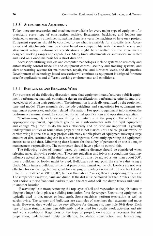
4.3.3 ACCESSORIES AND ATTACHMENTS
Today there are accessories and attachments available for every major type of equipment for
practically every type of construction activity. Excavators, backhoes, and loaders are
designed to use many attachments, making them very versatile machines to have on a project.
Equipment suppliers should be consulted to see what is available for a specific task. Acces-
sories and attachments must be chosen based on compatibility with the machine size and
attachment setup. Performance specifications might be consulted for the attachment’s
designed working ranges and capabilities. Many times attachments or accessories are rented
and used on a one-time basis for a short duration.
Accessories utilizing wireless and computer technologies include systems to remotely and
automatically control blade lift and equipment control, security and tracking systems, and
alert or warning systems for maintenance, repair, fuel and lubricant levels, and diagnostics.
Development of technology-based accessories will continue as equipment is designed for more
specific applications and different working environments and conditions.
4.3.4 EARTHMOVING AND EXCAVATING WORK
For purposes of the following discussion, note that equipment manufacturers publish equip-
ment performance manuals containing design specifications, performance criteria, and pro-
jected costs of using their equipment. The information is typically organized by the equipment
type and model. These manuals also include guidelines and suggestions for equipment use,
equipment accessories, and other related information. For specific equipment information, the
performance manual should be consulted for actual specifications and operating capacities.
‘‘Earthmoving’’ typically occurs during the initiation of the project. The selection of
appropriate equipment, equipment groups, or a subcontractor with the right equipment
and enough ‘‘big iron’’ to do the work efficiently and on time are important. Typically
underground utilities or foundation preparation is not started until the rough earthwork or
earthmoving is done. On a large project with many mobile pieces of equipment moving a large
amount of dirt, earthmoving can be a rather dangerous. Constantly operating the equipment
creates noise and dust. Minimizing these factors for the safety of personnel on site is a major
management responsibility. The contractor should have a plan to control this.
The following ‘‘rules of thumb’’ based on hauling distance should be considered when
selecting an earthmoving equipment. These are guidelines and job or site conditions that may
influence actual criteria. If the distance that the dirt must be moved is less than about 5000,then a bulldozer or loader might be used. Bulldozers cut and push the surface dirt using a
blade. Many times a bulldozer is the first piece of equipment on the job. Loaders are not very
effective for excavating, but are great for carrying or loading excavated dirt one bucket at a
time. If the distance is 3500 to 5000, but less than about 2 miles, then a scraper might be used.
The scraper can excavate, haul, and dump. If the dirt must be moved far than 2 miles, then the
best choice is to use front-end loaders to load the excavated soil into dump trucks and haul it
to another location.
‘‘Excavating’’ can mean removing the top layer of soil and vegetation as the job starts or
digging a huge hole to place a building foundation for a skyscraper. Excavating equipment is
typically used to dig, move, or load earth. Some machines perform excavation as well as
earthmoving. The scraper and bulldozer are examples of machines that excavate and move
earth. However, they would not be very effective for digging a square hole 30-ft deep. Each
type of excavating machine digs differently and is used for specific work activities and site
and work conditions. Regardless of the type of project, excavation is necessary for site
preparation, underground utility installation, foundation construction, and landscaping.
Douglas D. Gransberg / Construction Equipment for Engineers, Estimators, and Owners 037X_C004 Final Proof page 76 5.5.2006 11:22pm
76 Construction Equipment for Engineers, Estimators, and Owners

To accomplish this, one piece of machinery may be used, but most of the time a combination
of several pieces of equipments are required.
Hoes or excavators dig below grade or below the tires or tracks of the digging machine.
The area covered by the reach of the boom and arm of the excavator is called the digging
envelope. The depth to which the tip of the bucket teeth can reach below the machine tracks
to remove a bucketful of dirt is the digging depth. The deeper the hole, the longer the reach
required and the more stress placed on the boom and digging arm or stick of the machine.
Typically the deeper the hole, the bigger the machine required (unless possibly the soil is
noncohesive like sand). Figure 4.6 shows a typical side view of the designed working envelope
for an excavator.
Figure 4.6 shows the depth and height that the boom and arm can reach. When selecting
an excavator, not only must the basic machine be considered, but also the boom and arm
lengths and configurations as well. The optimum digging depth for a boom and arm is about
60 to 70% of the machine’s reach below grade. To dig a trench 100 deep, the excavator would
have a rated digging depth of about 170.The maximum depth of cut is the rated depth that the blade or the bucket can cut into the
soil in one pass. A pass can be considered one time through the cycle to fill the bucket or the
blade. An efficient operator will set the bucket or the blade just deep enough so that when one
E
8
F
FIGURE 4.6 Caterpillar excavator digging envelope. (Caterpillar Inc.)
Douglas D. Gransberg / Construction Equipment for Engineers, Estimators, and Owners 037X_C004 Final Proof page 77 5.5.2006 11:22pm
Earthmoving, Excavating, and Lifting Equipment Selection 77

motion or cycle is complete, the bucket or the blade will be filled to its rated capacity.
Whether a blade or a bucket, the deeper the cut, the more effort required for the equipment
to push the blade edge or the bucket teeth into and through the material to be excavated. The
deeper the penetration, the faster the blade or the bucket will fill. This shortens the push
distance or reduces the extension of the excavator’s boom, reducing the cycle time and
increasing the production. The trade-off is higher operation costs (more fuel, lubricant, higher
maintenance) because the machine must work harder to dig deeper. Optimum motor effi-
ciency (most economical operation) is achieved when the equipment excavates at the opti-
mum depth of cut for that size of motor, blade or bucket, and soil type.
Crowding force is the operational force required to push the edge or the bucket teeth into
the material face. It can be done mechanically, like an excavator or front shovel or by driving
into the material face like a loader. Breakout force is the operational force necessary to break
material apart once the bucket teeth or edge is set. Breakout force is developed by curling the
bucket downward ‘‘to the machine’’ like the excavator, or upward ‘‘away from the machine’’
like the front shovel. Greater force is required to break hard-packed material vs. loose sandy
material. Typically this means greater power and larger and more durable mechanical
components.
The horizontal angle in degrees (plan view) between the position of the bucket when it is
digging and its position when it discharges its load is the angle of swing. If the angle of swing
is increased, the digging and dumping cycle time is increased, thus reducing production and
increasing cost. Ideal production is achieved when the angle of swing equals 908. For
maximum efficiency when setting up an excavator to dig a trench and load dump trucks
with the excavated dirt, the loading path or spot of the trucks should be perpendicular to the
direction of the excavator’s tracks at 908 or less.
Figure 4.7 shows an excavator working on a surface below grade called a ‘‘bench.’’ The
figure also shows how a flat surface is created next to the hole where a concrete drainage
culvert is built. If the soil is really unstable, benching the edges of the hole may be required
instead of sloping. It is like stair-stepping the excavation. The bench can also serve another
purpose. In this case, the bench provides a surface for equipment to move and work. By working
on this lower surface, the excavator’s digging depth can be increased. Note the backhoe and
bulldozer in the background. Several excavators could be placed on ascending benches to
accommodate the depth of the dig. The bottom excavator is actually performing the excavation.
FIGURE 4.7 Excavator on a bench.
Douglas D. Gransberg / Construction Equipment for Engineers, Estimators, and Owners 037X_C004 Final Proof page 78 5.5.2006 11:22pm
78 Construction Equipment for Engineers, Estimators, and Owners

As it digs, it swings and dumps the spoil on the next bench up. Other excavators placed on the
benched areas pass the soil up out of the hole to be stored, spread, or hauled away.
Front shovels excavate above grade or into a material face or pile above the operating
surface. Their production cycle is similar to an excavator: dig, backtrack, dump, reposition,
and start over. Shovels digging into dense material typically operate on tracks. Shovels used
for material rehandling where digging is not required might operate on tires. Front-end
loaders operate similarly to front shovels, but are made for scooping at ground level, not
excavating. They are classified similarly by their upward scooping motion. For optimum
depth of cut, the bucket should be filled when it reaches the top of the face in one pass. This
depends on the type of material and the size of the bucket. Optimum digging height for most
shovels is between 40 and 50% of the rated maximum digging height. Breakout force is
developed by crowding the material away from the shovel by pushing the bucket teeth into
the material face and curling the bucket upward and toward the machine.
4.3.4.1 Earthmoving and Excavating Work Activities
The following discussion focuses on three common earthmoving and excavating work activ-
ities that require heavy equipment. The listed equipment packages are groups of heavy
equipment that typically work together to perform this task. Each piece of equipment in
the package plays a specific role in the series of activities required to perform the task
efficiently and effective. Equipment packages will vary based on the volume of work, desired
productivity, equipment availability, and specific work conditions and needs.
Rough site excavation or site leveling is done in the following sequence:
1. A surveyor stakes the area outlining the perimeter of the work and details the depth of
the cuts or fills.
2. A motor grader or bulldozer strips the surface of vegetation and debris.
3. A bulldozer with a ripper makes a pass over the area to be cut. It is advisable to rip a
couple of inches deeper than the actual cut to be made. The loosened soil provides
better traction for the bulldozer than a hard denser undisturbed surface.
4. A bulldozer removes the topsoil layer, pushing it into an out of the way stockpile to be
spread when final grading and landscaping are done.
5. The bulldozer pushes dirt into piles to be moved to areas of the site needing fill or to
be stockpiled at a remote location.
6. Several scrapers assisted by a bulldozer are used for mass surface excavation and to
haul the excavated dirt to another location on site.
7. A motor grader spreads the dumped dirt at the new location.
8. Excavators dig rough detention areas.
9. Excavated soil is loaded into dump trucks by front-end loaders to be hauled off site.
10. A bulldozer and motor grader are used to finish the rough leveling of the site and
detention areas.
Trench excavation for underground utilities is done in the following sequence:
1. A surveyor stakes the route of the trench and details the depth of cut.
2. A bulldozer and motor grader are used to grub, clear, and stabilize the surface.
3. An excavator or backhoe is used to scoop the dirt from the trench and pile it parallel to
the trench. (Dense soils might require use of a trencher.)
4. A forklift is used to unload, move, and hold the pipe while it is prepared for
installation.
Douglas D. Gransberg / Construction Equipment for Engineers, Estimators, and Owners 037X_C004 Final Proof page 79 5.5.2006 11:23pm
Earthmoving, Excavating, and Lifting Equipment Selection 79

5. The excavator lifts and places the pipe in the trench.
6. A front-end loader is used to backfill the trench when the installation is complete.
Foundation excavation and backfill is done in the following sequence:
1. A surveyor stakes the foundation perimeter and details the depth of cut once the rough
excavation is complete.
2. Excavators dig the hole and place the soil next to the hole.
3. Front-end loaders are used to move this soil to an on-site stockpile.
4. Or excavators dig the hole and directly load the dump trucks.
5. Or front-end loaders are used to load dump trucks, hauling the spoil to a remote
location.
6. Backhoes are used to excavate tighter areas and in the hole.
7. When the foundation is complete, front-end loaders move and dump stockpiled soil to
backfill against the foundation.
8. Small skid-steer loaders are used to carry dirt to confined areas and places where less
fill is required.
9. The backfill is then compacted against the foundation walls.
Table 4.5 lists common earthmoving and excavation work activities and the types of
equipment typically included in the equipment package.
4.4 EARTHMOVING EQUIPMENT SELECTION
Earthmoving equipment included in this discussion are:
. Bulldozers
. Front-end loaders
. Motor graders
. Scrapers
. Trucks
4.4.1 BULLDOZERS
A bulldozer is a tractor unit with a blade attached to its front. The blade is used to push,
shear, cut, and roll material ahead of the tractor. It is an ideal surface earthmover that
performs best at about 3mph. Each model of bulldozer has an operating range for blade size
and adjustment. Larger machines have greater operating ranges than smaller machines. A
larger machine can pitch and tilt deeper than a smaller machine typically. For heavy civil
work, bulldozer blade widths can range from 80 to 220 and operating weights can range from
about 7 tons to over 120 tons. Maximum digging depth ranges from about 1.50 to 2.50.Figure 4.8 shows a dozer that was used with the mega-terrain leveler shown in Figure 4.9,
excavating the foundation hole for a high-rise condominium building in Austin, Texas.
The hard clay-like soil had to be ground up, pushed into piles by the bulldozer, and then
loaded by front-end loaders into dump trucks to be hauled away. This was more efficient than
using excavators due to the denseness of the soil.
The bar connecting the blade to the body of the bulldozer is parallel to the travel surface
and just above it. This positioning can deliver maximum forward force to push a pile of dirt or
a scraper. Note the pistons connected to the blade. These pistons control the tilt of the blade,
Douglas D. Gransberg / Construction Equipment for Engineers, Estimators, and Owners 037X_C004 Final Proof page 80 5.5.2006 11:23pm
80 Construction Equipment for Engineers, Estimators, and Owners