Instruction Sheet Slim 5 SERIES - Pilote Films
9
Slim 5 SERIES For 29, 37, 43 Rackspace Models Only Instruction Sheet I-0600 Rev M U L R C US LISTED Thank you for purchasing the Slim 5 Series Rack. Please read all instructions thoroughly before assembling this product. THANK YOU
Transcript of Instruction Sheet Slim 5 SERIES - Pilote Films

Slim 5 SERIESFor 29, 37, 43 Rackspace Models Only
Instruction Sheet
I-0600 Rev M
ULRC US
LISTED
Thank you for purchasing the Slim 5 Series Rack. Please read all instructions thoroughly before assembling this product.
THANK YOU
WARNING: Failure to read, understand and follow the following information can result inserious personal injury, damage to the equipment or voiding of the warranty.
AVERTISSEMENT: Ne pas lire, comprendre et suivre les informationssuivantes peut entraîner des blessures graves, des dommages à l'équipementou de la nullité de la garantie.
Page 2
CAUTION: To avoid an unstable condition, place heavier components at the bottom of theenclosure. When more than one component is placed in the enclosure, begin at the bottomof the enclosure and place equipment at the lowest available point, evenly distribute weight(horizontally) within the enclosure.
Component weight should be distributed as follows:• 1/2 of the total component weight (at a minimum) placed in the bottom third of the cabinet• 1/4 of the total component weight (at a maximum) placed in the middle third of the cabinet• 1/4 of the total component weight (at a maximum) placed in the top third of the cabinet
ATTENTION: Pour éviter un état instable, placez composants les plus lourds aufond de l'enceinte. Lorsque plus d'un composant est placé dans la enceinte, commencer par le bas de l'enceinte et placer l'équipement à la point le plus basdisponible, de distribuer uniformément le poids (horizontalement) dans le enceinte.
Le poids des composants devrait être réparti comme suit:• 1/2 du poids total de la composante (au minimum) placé dans le tiers inférieur de l'armoire• 1/4 du poids total de la composante (au maximum) placé dans le tiers médian de l'armoire• 1/4 du poids total de la composante (au maximum) placé dans le tiers supérieur de l'armoire
IMPORTANT SAFETY INSTRUCTIONS / INSTRUCTIONS IMPORTAANTES SUR LA SÉCURITÉ
DANGER HAZARDOUS VOLTAGE/DANGER HAUTE TENSION
The lightning flash with the arrowhead symbol, within an equilateraltriangle is intended to alert the user to the presence of uninsulateddangerous voltage within the product’s enclosure that may be ofsufficient magnitude to constitute a risk of electric shock to persons.
L'éclair avec le symbole de flèche dans un triangle équilatéral estdestiné à alerter l'utilisateur de la présence d'une tension dangereusenon isolée dans l'enceinte du produit qui peut être d'une ampleursuffisante pour constituer un risque de choc électrique pour lespersonnes.
CAUTION/ATTENTION The exclamation point within an equilateraltriangle is intended to alert the user to the presence of importantoperating and maintenance (servicing) instructions in the literatureaccompanying the appliance.
Le point d'exclamation dans un triangle équilatéral est destiné àalerter l'utilisateur de la présence d'importants instructions d’opérationet de maintenance (entretien) dans la documentation accompagnantl'appareil.
SAVE ALL INSTRUCTIONS / CONSERVER CES INSTRUCTIONS

CAUTION: All installation and assembly steps must be performed by qualified personnel.
ATTENTION: Toutes installation et de montage étapes doivent être effectuées par dupersonnel qualifié.
CAUTION: Ensure that the floor has a structural load capacity that will support the weight ofthe cabinet fully loaded with equipment.
ATTENTION: Veiller à ce que le sol a une capacité de charge structurelle qui supporter lepoids de le cabinet entièrement chargé avec l'équipement.
CAUTION: The following parts are not effectively bonded to the protective earth terminal: Rack rails, lace bars, Lever Lock™, shelves, baffle, blanking panels, and cable management. If any part needs to be bonded to the protective earth terminal it shall be done in accordance with Article 250 of the National Electrical Code.
ATTENTION: Les pièces suivantes ne sont pas correctement liés à la borne de terre de protection: rails de rack, des bars de dentelle, Lever Lock ™, des étagères, des chicanes, des panneaux d'obturation, et la gestion des câbles. Si une partie doit être lié à la borne de terre de protection, il doit être fait conformément à l'article 250 du Code national de l'électricité.
CAUTION: Power cord(s), for fans or other accessories, need to be secured to ensure thatthey are routed away from pinch points and moving parts.
ATTENTION: Le cordon d'alimentation(s), pour les fans ou autres accessoires, doivent êtrefixé à veiller à ce que ils sont acheminés loin des points de pincement et des pièces mobiles.
Page 3
IMPORTANT SAFETY INSTRUCTIONS / INSTRUCTIONS IMPORTAANTES SUR LA SÉCURITÉ
CAUTION: To reduce the risk of personal injury, these mounting instructions must be followed and proper weight capacities must be observed.
ATTENTION: Pour réduire le risque de blessures, ces instructions de montage doivent être respectées et les capacités de poids appropriées doivent être respectées.
WEIGHT RATINGS
Model Weight RatingAll 400 lbs.

CAUTION: Use caution when moving the cabinets with casters installed. There is apossibility of tilting. Always move cabinet over smooth floor surfaces and a short distanceonly. The enclosure should only be moved by pushing on the front or rear of the cabinet. DONOT push from the side.
ATTENTION: Soyez prudent lors du déplacement des armoires à roulettes installées. Il seagit d'un possibilité de basculement. Toujours déplacer l'armoire sur les surfaces lisses et àune courte distance seulement. L'enceinte ne doit être déplacé en poussant sur le devant ouà l'arrière de l'armoire. FAIRE PAS pousser de côté.
CAUTION: Casters (if used) are not intended to support excessive cabinet loads for extendedperiods of time. Please refer to caster base instruction sheet for recommended weightcapacity. Always use levelers to stabilize the cabinet after locating.
ATTENTION: Roulettes (le cas échéant) ne sont pas destinés à supporter des chargesexcessives du Cabinet pour prolongée périodes de temps. Se il vous plaît se référer àCaster feuille d'instructions de base pour poids recommandé la capacité. Toujours utiliserniveleurs pour stabiliser l'armoire après avoir localisé.
CAUTION: Do not attempt to unload or move the enclosures alone. Make sure to havesufficient amount of personnel and equipment to safely move this product.
ATTENTION: Ne essayez pas de décharger ou déplacer les enceintes seul. Assurez-vousd'avoir quantité suffisante de personnel et de matériel pour déplacer ce produit en toutesécurité.
Page 4
IMPORTANT SAFETY INSTRUCTIONS / INSTRUCTIONS IMPORTAANTES SUR LA SÉCURITÉ

Heights: 29, 37, and 43 RUsDepths: 20” and 26”Load Ratings: 400 lbs. load rating
Added Weight (Loading): Total added weight should be distributed as follows:• 1/2 of the total added weight (at a minimum) placed in the bottom third of the enclosure• 1/4 of the total added weight (at a maximum) palced in the middle third of the enclosure• 1/4 of the total added weight (at a maximum) placed in the top third of the enclosure
• 9/16” Wrench• 1/8” Balldrive Hex Key (Included)
Page 5
SPECIFICATIONS
SUPPLIED COMPONENTS AND HARDWARE
REQUIRED TOOLS
Rackrail Channels (x2 Left; x2 Right)
5/16-18 FlangeNut (x20)
Top Panel Base Panel
#10 NylonWasher (x12)
10-32 x 5/8 FlatHead Hex Screw (x4)
10-32 x 1/2 FlatHead Hex Screw (x16)
Trim Panels (x2)Braces (x2)

Page 6
ASSEMBLY
1. Attach the (4) rackrail channels to the top and base panels by passing (4) rackrail threads on each rail through the panel holes and loosely screwing on the flange nuts. Do not tighten. (FIGURE A) NOTE: Ensure cable knockouts on the top and bottom panels are facing the same side.
2. Attach (2) 10-32 X 1/2 hex screws to each corner of the front and rear of the top and base panels. Firmly tighten the hex screws. (FIGURE B)
1/2” LENGTHHEX SCREWS
FAN KNOCKOUTS FOR TOP MOUNTED
FANS (PART# 5-FAN-K;INCLUDES 2 FANS)
TOP
BOTTOM
TRIM PANEL (TOP AND BOTTOM)
KNOCKOUTS
FRONT
REAR FLANGE NUT
RACKRAIL
FIGURE A
FIGURE B
Page 7
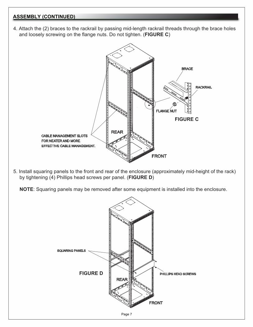
ASSEMBLY (CONTINUED)
4. Attach the (2) braces to the rackrail by passing mid-length rackrail threads through the brace holes and loosely screwing on the flange nuts. Do not tighten. (FIGURE C)
5. Install squaring panels to the front and rear of the enclosure (approximately mid-height of the rack) by tightening (4) Phillips head screws per panel. (FIGURE D) NOTE: Squaring panels may be removed after some equipment is installed into the enclosure.
FIGURE C
FIGURE D
CABLE MANAGEMENT SLOTS FOR NEATER AND MORE EFFECTIVE CABLE MANAGEMENT.
BRACE
FLANGE NUT
FRONT
REAR
RACKRAIL
SQUARING PANELS
PHILLIPS HEAD SCREWS
REAR
FRONT

Page 8
ASSEMBLY (CONTINUED)
6. Lay the enclosure on a flat surface and tighten all of the flange nuts. Do not overtighten. (FIGURE E)
NOTE: The enclosure must be laid on a flat surface to prevent the assembled frame from going cubically out of square.
7. Attach (2) trim panels to the front of the top and base panels using (4) 10-32 x 5/8 hex screws. Do not overtighten. (FIGURE F)
FIGURE E
FIGURE F
GROUND PLANE
CORRECT INCORRECT
5/8” LENGTHHEX SCREWS
TRIM PANEL
WARRANTYMiddle Atlantic Products, Inc. (the "Company") warrants the product to be free from defects in material or workmanship under normal use and conditions for the lifetime of the product. The Company's entire liability to the purchaser, and the purchaser's (or any other party's) sole and exclusive remedy, under this warranty shall be limited, at the Company's option, to either (a) return of and refund of the price paid for, or (b) repair or replacement at the Company's factory of the products purchased, or any part or parts thereof, which the Company has determined to be defective after inspection thereof at the Company's factory. This warranty does not cover damage due to acts of God,accident, misuse, abuse or negligence by parties other than the Company, or any modification or alteration of the products. In addition, this warranty does not cover damage due to improper handling, assembly, installation or maintenance.
THIS WARRANTY IS IN LIEU OF ALL OTHER WARRANTIES OF ANY KIND, EITHER EXPRESSED OR IMPLIED, INCLUDING, BUT NOT LIMITED TO, IMPLIED WARRANTIES OF MERCHANTABILITY AND FITNESS FOR A PARTICULAR PURPOSE.
TO THE MAXIMUM EXTENT PERMITTED BY APPLICABLE LAW, IN NO EVENT SHALL THE COMPANY BE LIABLE FOR ANY SPECIAL, INCIDENTAL, INDIRECT, OR CONSEQUENTIAL DAMAGES WHATSOEVER (INCLUDING, WITHOUT LIMITATION, DAMAGES FOR LOSS OF BUSINESS PROFITS, BUSINESS INTERRUPTION OR ANY OTHER PECUNIARY LOSS) ARISING OUT OF THE USE OF THE PRODUCTS PURCHASED, EVEN IF THE COMPANY HAS BEEN ADVISED OF THE POSSIBILITY OF SUCH DAMAGES. THE COMPANY'S LIABILITY TO THE PURCHASER (OR ANY OTHER PARTY) HEREUNDER, IF ANY, SHALL IN NO EVENT EXCEED THE PURCHASE PRICE OF THE PRODUCTS PAID TO THE COMPANY.
Corporate HeadquartersCorporate Voice 973-839-1011 - Fax 973-839-1976 / International Voice +1 973-839-8821 - Fax +1 973-839-4982middleatlantic.com - [email protected] Atlantic CanadaVoice 613-836-2501 - Fax 613-836-2690 / middleatlantic.ca - [email protected] DistributionUSA: NJ - CA - IL Canada: ON - BCAt Middle Atlantic Products we are always listening. Your comments are welcome.
Middle Atlantic Products is an ISO 9001 Registered Company.
Page 9
OPTIONS
The following Slim 5 options are available to complete your installation:
• Solid (DO-5-xx) and plexiglass (DOP-5-xx) front door• Decorative (TSP-5-xx-yy, Top and Sides) and steel (SP-5-xx) side panels• Rear access panels (RAPxx)• Additional rackrail (5ARxx)• Cable chase (5CCxx)• Commercial grade casters (5W and 5WL) and caster bases (CBS-5 and CBS-5-26)• Fine floor casters (5WR and 5WLR) and caster bases (CBS-5R and DBS-5-26R)• Decorative trim panels (5-CAVTRIM and 5-BAVTRIM) and trim strips (TS, TA, and TC)• Runner kit (5-RS20 and 5-RS26)• Fan kit (5-FAN-K)
NOTE: See our catalog or visit www.middleatlantic.com for additional options.