INSTRUCTION MANUAL - eatoncorp.com.aupub/@oceania/@elec/... · 7.2 What is earth fault loop...
36
KEW 6010B MULTI-FUNCTION TESTER INSTRUCTION MANUAL KYORITSU ELECTRICAL INSTRUMENTS WORKS,LTD.
Transcript of INSTRUCTION MANUAL - eatoncorp.com.aupub/@oceania/@elec/... · 7.2 What is earth fault loop...

KEW 6010B
MULTI-FUNCTION TESTER
INSTRUCTION MANUAL
KYORITSU ELECTRICAL INSTRUMENTSWORKS,LTD.

1.Safe Testing.................................................................................... 12.Instrument Layout........................................................................... 33.Features.......................................................................................... 44.Specification................................................................................... 65.Continuity (resistance) tests........................................................... 10 5.1 Test procedure...................................................................... 10
6.Insulation Tests............................................................................... 126.1 The nature of insulation resistance........................................ 126.1.2 Capacitive current.................................................................. 126.1.3 Conduction current................................................................ 136.1.4 Surface leakage current........................................................ 136.1.5 Total leakage current..............................................................136.2 Damage to voltage sensitive equipment................................ 14 6.3 Preparation for measurement................................................ 156.4 Insulation resistance measurement....................................... 15
7. Loop Impedance Tests.................................................................. 177.1 Voltage measurement............................................................177.2 What is earth fault loop impedance?..................................... 177.3 Automatic over-temperature cut-out...................................... 187.4 The loop impedance test....................................................... 197.5 Loop impedance at 3 phase equipment................................ 20
8.RCD/Uc Tests................................................................................. 218.1 Purpose of RCD Test............................................................ 218.2 What does the RCD test really do?....................................... 218.3 What is Uc?........................................................................... 228.4 Uc Testing............................................................................. 238.5 Operation of KEW 6010B RCD testing.................................. 238.6 RCD testing........................................................................... 238.6.1 "NO TRIP" and "TRIP" test.................................................... 238.6.2 "FAST TRIP" test................................................................... 258.6.3 Testing DC sensitive RCDs................................................... 258.6.4 Testing Auto Ramp................................................................ 258.7 Testing time delayed RCD's.................................................. 26
9.Store / Recall a measured result.................................................... 279.1 How to store the data............................................................ 279.2 Recall the stored data............................................................ 289.3 Delete the stored data........................................................... 299.4 Transfer the stored data to PC.............................................. 30
10.Battery / Fuse replacement............................................................ 3111.General.......................................................................................... 3212.Servicing........................................................................................ 3213.Case, Strap and Shoulder-pad assembly...................................... 33
CONTENTS

― 1 ―
1. SAFE TESTING (READ BEFORE USING)
Electricity is dangerous and can cause injury and death. To avoid possibleelectric shock, personal injury or damage of instrument, always treat it with thegreatest of respect and care. If you are not quite sure how to proceed, stop andtake advice from a qualified person.
1. This instrument must only be used by a competent and trained person andoperated in strict accordance with the instructions. KYORITSU will notaccept liability for any damage or injury caused by misuse or non-compliance with the instructions or with the safety procedures.
2. It is essential to read and to understand the safety rules contained in theinstructions. They must always be observed when using the instrument.
3. This instrument is only intended for single phase operation at 230V AC+10%, -15% phase to earth or phase to neutral operation, and then only forLoop, RCD and Uc testing. For use in the continuity testing and insulationtesting modes this instrument must be used ONLY on circuitswhich are de-energized.
4. Verify the tester's operation by measuring a known voltage before and afterusing it.
5. When conducting tests do not touch any exposed metalwork associated withthe installation. Such metalwork may become live for the duration of thetest.
6. Never open the instrument case (except for fuse and batteryreplacement and in this case disconnect all leads first) because dangerousvoltages are present. Only fully trained and competent electrical engineersshould open the case. If a fault develops, return the instrument to yourdistributor for inspection and repair.
7. If the overheat symbol appears in the display " " disconnect theinstrument from the mains supply and allow to cool down.
8. For loop impedance tests to prevent unwanted tripping during loop testingall residual current devices(RCDs) must be taken out of the circuit andtemporarily replaced with a suitably rated MCB unit. The RCD must bereplaced after the loop test is completed.
9. If abnormal conditions of any sort are noted (such as a faulty display,unexpected readings, broken case, cracked test leads, etc) do not use thetester and return it to your distributor for repair.
10. For safety reasons only use accessories (test leads, probes, fuses, cases,etc) designed to be used with this instrument and recommended byKYORITSU. The use of other accessories is prohibited as they are unlikely tohave the correct safety features.
11. When testing, always be sure to keep your fingers behind the safety barrierson the test leads.
12. During testing it is possible that there may be a momentary degradation ofthe reading due to the presence of excessive transients or discharges onthe electrical system under test. Should this be observed, the test must berepeated to obtain a correct reading. If in doubt, contact your distributor.
13. The sliding shutter on the back of the instrument is a safety device. Theinstrument should not be used if it is damaged or impaired in any way, but

― 2 ―
returned to your distributor for attention.14. Do not operate the function switch while the instrument is connected to a
circuit. If, for example, the instrument has just completed a continuity testand an insulation test is to follow, disconnect the test leads from the circuitbefore moving the function switch.
15. Do not rotate function switch when test button is depressed. If the functionswitch is inadvertently moved to a new function when the test button isdepressed or in lock-down position the test in progress will be halted. Toreset, release test button and press again to restart testing on new function.
16. THE WIRING CHECK LED (P-E, P-N) of this instrument is to protect the userfrom electrical shock resulting from incorrect connection of Line and Neutralor Line and Earth.When the Neutral and Earth conductors are incorrectlywired, the WIRING CHECK LED function cannot identify the incorrectconnection. Other procedures and test must be conducted to check andconfirm that the wiring is correct prior to making measurement. Do not usethis instrument to check the correct wiring of the power supply. Kyoritsu willnot be held liable for any accident that may result from incorrect wiring ofthe power supply line.
17. Use a damp cloth and detergent for cleaning the instrument. Do not useabrasives or solvents.
CAT.Ⅲ
Caution, risk of electric shock
Protection against wrong connection is up to 440V
Caution (refer to accompanying instruction manual)
Earth Ground
protected throughout by DOUBLE INSULATION or REINFORCED INSULATION
Designed to protect against transient overvoltages in a building wiring installation (low-voltage distribution level)
Symbols used on the instrument

― 3 ―
2. INSTRUMENT LAYOUT
Test Lead with IEC Connector
Test Lead for Continuity and Insulation Testing
LCD DISPLAY
Fig.1
IΔn SELECT SWITCH: Available FUNCTION NO.6, 7, 8, 9, 10(MEMORY SELECT SWITCH)0°/180°SELECT SWITCH: Available FUNCTION NO.4, 6, 7, 8, 9(MEMORY RECALL SWITCH)UL VALUE SELECT SWITCH: Available FUNCTION NO.6, 7, 8, 9(ENTER SWITCH)AUTO NULL SWITCH: Available FUNCTION NO.1(MEMORY CLEAR SWITCH)MEMORY MODE SWITCH(MEMORY MODE EXIT SWITCH)
The switch name shown in ( ) is used in MEMORY MODE.

― 4 ―
KEW 6010B Multi-Function tester performs six functions in one instrument.
1. Continuity tester2. Insulation resistance tester (500V/1000V)3. Loop impedance tester4. RCD tester5. Uc tester6. Mains voltage warning when operating the Loop, RCD and Uc mode.Above test results: item1 through 5, can be saved to the internal memory; andthey can be recalled whenever necessary.Data can be transferred from KEW6010B to PC by using MODEL8212 and"KEW Report" (Optional accessory).
The tester is designed to Safety StandardIEC 61010-1 CAT III (300V) Pollution degree 2, IEC 61557-1, 2, 3, 4, 6, 10.
Drip-proof construction in conformance with IP40, IEC 60529.
The instrument is supplied with:-1. KAMP10 lead for Loop/RCD/Uc testing at socket outlets.2. Model 7025 lead for Continuity and Insulation testing.
Continuity and insulation resistance functions have the following features:-Rated current Continuity: 200mA as required in IEC 61557-4
(Buzzer sounds when test current exceeds 200mA)Insulation: 1mA as required in IEC 61557-2
Live circuit warning A colour coded LED and buzzer warn if thecircuit under test is live.
Continuity Null Allows automatic subtraction of test leadresistance from continuity measurements.
Auto discharge Electric charges stored in capacitive circuitsare discharged automatically after testing byreleasing the test button.
Loop impedance, RCD and Uc testing functions have the following features:-Voltage level Supply voltage is displayed when the
instrument is connected to the supply until thetest button is pressed.
3. FEATURES

― 5 ―
Wiring check Three LEDs indicate if the wiring of the circuitunder test is correct.
Over temperature Detects overheating of the internal resistorprotection (used for Loop tests) and of the current control
MOS-FET (used for RCD and Uc tests)displaying a warning symbol " " andautomatically halting further measurements.
15mA Loop Loop impedance 2000Ω range measurementmeasurement is carried out with low test current (15mA).
The current will not cause tripping out involvedRCD even the one with the lowest nominaldifferential current (30mA).
DC Test Allows testing of RCDs which are sensitive toDC fault currents.
Phase angle selector The test can selected from either the positive(0°) or from the negative (180°) half-cycle ofvoltage.This will prevent tripping of somepolarized RCDs when Loop testing(20Ω rangeonly) and may give a more accurate readingwhen testing RCDs.
UL(touch voltage limit) Select UL 25V or 50V with pressing the UL value change and Uc value select switch. Where Uc value exceeds monitoring UL, "UcH v" will be displayed without starting
the RCD test. And at Uc range, can monitor the Uc value.
Other features:-Auto data hold Holds the displayed reading until pressed or
rotated any switches after the test is complete.Auto power off Automatically switches the instrument off after
a period of approximately 10 minutes. Thepower-off state returns to normal when thefunction switch is re-set to any position.
Data memory Can store 300 measured results.Indication Flickers while the instrument is measuring.
Optional Accessory Model7133 (OMA DIEC) distribution board orlighting circuit test lead for LOOP/RCD/Uctesting. Data can be transferred to PC viaOptical Adapter Model 8212 (with PC software"KEW Report")

+5% +15%rdg±8dgt
5mA at IΔn=10mA
15mA at IΔn=30/100mA
150mA at IΔn=300/500mA
Test Current
AccuracyTest Current Trip Time
Open CircuitVoltage (DC)
Short CircuitCurrent Range Accuracy
Greater than 6 V Greater than200mA@2Ω
20/200ΩAuto - Ranging
± (3%rdg + 4dgt)± (3%rdg + 3dgt)
Up to 2ΩOver 2Ω
― 6 ―
4. SPECIFICATION
Measurement Specification
AccuracyRange
100V
Rated Voltage (AC)
230V+10%-15% 50Hz
@ KAMP10 Test lead
Continuity
Rated Voltage(AC)
Nominal Test Currentat 0Ω External Loop Range Accuracy
230V+10%-15%50Hz
25A/10ms
15mA/350ms max.± (3%rdg + 8dgt)
20Ω
2000Ω
Loop Impedance
FunctionRated
Voltage(AC)
Test CurrentTest
CurrentDuration
x1/2
x1
FAST
DC
AutoRamp
230V+10%-15%50Hz
10/30/100/300/500mA
10/30/100/300/500mA
150mA
10/30/100/300mA
500mAGoes up by 10% from 20%to 110% of IΔn. 300ms x 10
± (1%rdg +3dgt)
-
2000ms
2000ms
50ms
2000ms
200ms
-8% -2%
+2% +8%
±10%
±4%
RCD
Uc
Function Open CircuitVoltage (DC) Rated Current Range Accuracy
500V
1000V
500V+20%-0%
1000V+20%-0%
1mA or greater@ 500kΩ
1mA or greater@ 1MΩ
± (3%rdg + 3dgt)20/200MΩAuto-Ranging
Insulation Resistance

Rated Voltage (AC) Measuring Range (AC) Accuracy
100-250V 50Hz 100-300V 3% rdg
― 7 ―
To prevent wrong connection of test leads and to maintain safety, the dedicatedterminals used for continuity and insulation tests are automatically coveredwhen using the terminals for Loop impedance, RCD and Uc tests.
Typical Number of Tests (central tendency for supply voltage up to 8V at R6P)Continuity Ranges : Approx. 700 times min. at load 1ΩInsulation Resistance Ranges : Approx. 1200 times min. at load 0.5MΩ(500V)
Approx. 900 times min. at load 1MΩ(1000V)LOOP/RCD/Uc Ranges : Operational lifetime:5h (In case of continuous
duty)
Operating error
● Operating Errors of Continuity (IEC 61557-4)/Insulation Resistance (IEC 61557-2)
The influencing variations used for calculating the operating error are denoted as follows;Temperature : 0℃ and 35℃Supply voltage : 8V to 13.8V
● Operating Error of Loop Impedance (IEC 61557-3)
The influencing variations used for calculating the operating error are denoted as follows:Temperature : 0℃ and 35℃Phase angle : At a phase angle 0°to 18°System frequency : 49.5Hz to 50.5HzSystem voltage : 230V+10%-15%Supply voltage : 8V to 13.8V
Voltage Measurement
@ Loop/RCD/Uc Range
Function Range
20Ω
200Ω
500V
1000V
0.20-19.99Ω
20.0-199.9Ω
0.50 - 199.9MΩ
1.00 - 199.9MΩ
Measuring range to keep operating error
Maximum percentageoperating error
±30%
Continuity
lnsulationResistance
Range
0.4-19.99Ω
100-1999Ω
Measuring range to keepoperating error
Maximum percentageoperating error
±30%20Ω
2000Ω

― 8 ―
● Operating Error of RCD (IEC 61557-6)
The influencing variations used for calculating the operating error are denoted as follows:Temperature : 0℃ and 35℃Earth electrode Resistance (shall not exceed below) :
System voltage : 230V+10%-15%Supply voltage : 8V to 13.8V
Instrument dimensions:- 175 X 115 X 86mmInstrument weight:- 840g including batteries.Reference conditions Specifications are based on the following conditions
except where otherwise stated:-1.Ambient temperature: 23± 5:2.Relative humidity 45% to 75%3.Position: horizontal4.AC power source 230V, 50Hz5.DC power source: 12.0 V, ripple content 1% or
less6. Altitude up to 2000m, Indoor use
Battery type Eight R6 or LR6 batteries.Low battery warning " " symbol appears in the display if the battery
voltage drops below 8V.Operating temperature 0 to +40:, relative humidity 80% or less, noand humidity. condensation.
Storage temperature -20 to +60℃, relative humidity 75% or less, noand humidity condensation.
Surge protection transient overvoltage 4000VInsulation resistance greater than 50MΩ at 1000V DC
(between enclosures and electrical circuits)
Function-10% - 0%0% -+10%
-10% -+10%
Operating error of trip current×1/2×1, FASTAuto Ramp
Earth electrode resistance (Ωmax.)IΔn (mA)
UL50V200060020013080
1030100300500
20006002006540
UL25V

LED indication of live Illuminates if there is an alternating voltage of 20Vcircuit warning AC or more in the circuit under test before Continuity
or Insulation resistance tests. When DC voltage isdetected across the measuring terminal the LEDlights up.
LED indication of The P-E and P-N LEDs illuminate when the wiring ofcorrect polarity the circuit under test is correct. The reverse LED
" " is lit when P and N are reversed.Display The liquid crystal display has 3 1/2 digits with a
decimal point and units of measurement (Ω, MΩ, V,mA and ms) relative to selected function.
Overload protection The continuity test circuit is protected by a 0.5 A 600V fast acting (HRC) ceramic fuse mounted in thebattery compartment, where a spare fuse is alsostored.The insulation resistance test circuit is protected bya resistor against 1200 V AC for 10 seconds.
Mains Voltage On connecting test leads to the circuit under test atIndication Loop, RCD and Uc ranges, the LCD reads VL-PE.
Indications are as follow:Less than 100V : "Lo v"100V259V : voltage value and " "260V300V : voltage value and "Hi v"
alternately, and " "Over than 300V : "Hi v" and " "
― 9 ―

― 10 ―
5. CONTINUITY (RESISTANCE) TESTS
WARNINGENSURE THAT CIRCUITS TO BE TESTED ARE NOT LIVE.
DISCONNECT THE INSTRUMENT FROM THE CIRCUIT UNDER TEST BEFORE OPERATING THE FUNCTION SWITCH.
TO SELECT THE LOW RESISTANCE RANGE SELECT "CONTINUITY"
5.1 Test ProcedureThe object of continuity testing is to measure only the resistance of the parts ofthe wiring system under test. Resistance value can be obtained by applying acertain current to the resistor under test, and measuring the voltage generatedon the both sides of the resistor under test.
Resistance value(Ω) = Voltage(V) / Current(A)This measurement should not include the resistance of any test leads used. Theresistance of the test leads needs to be subtracted from any continuitymeasurement. KEW 6010B is provided with a continuity null feature whichallows automatic compensation for any test lead resistance.
Proceed as follows:-1.Select the continuity test by rotating the function switch.2.Connect the ends of the test leads firmly together (see Fig 2) and press and
lock down the test button. The value of the lead resistance will be displayed.3.Operate the AUTO NULL SWITCH, this will null out the lead resistance
and the indicated reading should go to zero.
Fig 2

― 11 ―
4.Release the test button. Press the test button and ensure the displayreads zero before proceeding. While using the Continuity null function," " appears on the LCD. The null value will be stored even if power offthe instrument. The memorized null value can be cancelled bydisconnecting the test leads and pushing the AUTO NULL SWITCH withthe test button pressed or locked. CAUTION-before taking anymeasurements always check the leads have been zeroed.
5.Connect the test leads to the circuit whose resistance is required (see Fig3 for a typical connection arrangement). Having first made sure that thecircuit is not live. Note that the live circuit warning LED will illuminateif the circuit is live - but check first anyway!
6.Press the test button and read the circuit resistance from the display. Thereading will have the test lead resistance already subtracted.
Note: ●If the circuit resistance is greater than 20Ω the instrument will autorange tothe 200Ω, and is greater than 200Ω the overrange symbol "OL" will remaindisplayed.
Warning:Measurements may be adversely affected by impedances of connectedcircuits in parallel or transient currents.
Fig 3
― 12 ―
WARNINGENSURE THAT CIRCUITS TO BE TESTED ARE NOT LIVE.
DISCONNECT THE INSTRUMENT FROM THE CIRCUIT UNDER TEST BEFORE OPERATING THE FUNCTION SWITCH.
TO S E LECT TH E I NS U LATION R ES ISTANCE RANG E S E LECT“INSULATION”
6.1 The nature of insulation resistanceLive conductors are separated from each other and from earth metal byinsulation, which has a resistance which is high enough to ensure that thecurrent between conductors and to earth is kept at an acceptably low level.Ideally insulation resistance is infinite and no current should be able to flowthrough it. In practice, there will normally be a current between live conductorsand to earth, and this is known as leakage current. This current is made up ofthree components, which are:-1.capacitive current2.conduction current, and3.surface leakage current.
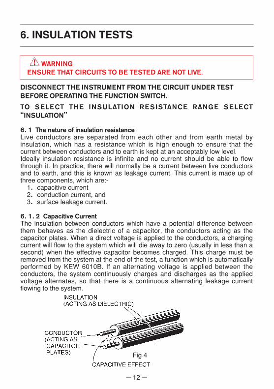
6.1.2 Capacitive CurrentThe insulation between conductors which have a potential difference betweenthem behaves as the dielectric of a capacitor, the conductors acting as thecapacitor plates. When a direct voltage is applied to the conductors, a chargingcurrent will flow to the system which will die away to zero (usually in less than asecond) when the effective capacitor becomes charged. This charge must beremoved from the system at the end of the test, a function which is automaticallyperformed by KEW 6010B. If an alternating voltage is applied between theconductors, the system continuously charges and discharges as the appliedvoltage alternates, so that there is a continuous alternating leakage currentflowing to the system.
6. INSULATION TESTS
Fig 4

6.1.3 Conduction CurrentSince the insulation resistance is not infinite, a small leakage current flowsthrough the insulation between conductors. Since Ohm's Law applies, theleakage current can be calculated from
Leakage current (µA) = applied voltage (V)insulation resistance (MΩ)
Fig 5
6.1.4 Surface Leakage CurrentWhere insulation is removed, for the connection of conductors and so on,current will flow across the surfaces of the insulation between the bareconductors. The amount of leakage current depends on the condition of thesurfaces of the insulation between the conductors. If the surfaces are clean anddry, the value of the leakage current will be very small. Where the surfaces arewet and/or dirty, the surface leakage current may be significant. If it becomeslarge enough, it may constitute a flashover between the conductors.Whether this happens depends on the condition of the insulation surfaces andon the applied voltage; this is why insulation tests are carried out at highervoltages than those normally applying to the circuit concerned.
Fig 6
6.1.5 Total Leakage CurrentThe total leakage current is the sum of the capacitive, conduction and surfaceleakage current described above. Each of the currents, and hence the totalleakage current, is affected by factors such as ambient temperature, conductortemperature, humidity and the applied voltage.If the circuit has alternating voltage applied, the capacitive current (6.1.2) willalways be present and can never be eliminated. This is why a direct voltage isused for insulation resistance measurement, the leakage current in this case
― 13 ―

― 14 ―
Insulation resistance (MΩ) =Test voltage (V)
Leakage current (µA)
As the capacitance of the system charges up, so the charging current falls tozero and a steady insulation resistance reading indicates that the capacitance ofthe system is fully charged. The system is charged to the full test voltage, andwill be dangerous if left with this charge. KEW 6010B provides an automaticpath for discharging current as soon as the test button is released to ensure thatthe circuit under test is safely discharged.If the wiring system is wet and/or dirty, the surface leakage component of theleakage current will be high, resulting in low insulation resistance reading. In thecase of a very large electrical installation, all the individual circuit insulationresistances are effectively in parallel and the overall resistance reading will below. The greater the number of circuits connected in parallel the lower will bethe overall insulation resistance.
6.2 Damage to Voltage-Sensitive EquipmentAn increasing number of electronic-based items of equipment are beingconnected to electrical installations. The solid state circuits in such equipmentare likely to be damaged by the application of the levels of voltage used to testinsulation resistance. To prevent such damage, it is important that voltage-sensitive equipment is disconnected from the installation before the test iscarried out and reconnected again immediately afterwards. The devices whichmay need to be disconnected before the test include:-
● Electronic fluorescent starter switches● Passive infra-red detectors (PIRs)● Dimmer switches● Touch switches● Delay timers● Power controllers● Emergency lighting units● Electronic RCDs● Computers and printers● Electronic point-of-sale terminals (cash registers)● Any other device which includes electronic components.
quickly falling to zero so that it has no effect on the measurement. A highvoltage is used because this will often break down poor insulation and causeflashover due to surface leakage (see 6.1.4), thus showing up potential faultswhich would not be present at lower levels. The insulation tester measures theapplied voltage level and the leakage current through the insulation. Thesevalues are internally calculated to give the insulation resistance using theexpression:-

― 15 ―
6.3 Preparation for measurementBefore testing, always check the following:-1. The low battery Indication " " is not displayed2. There is no visually obvious damage to the tester or to the test leads.3. Test the continuity of the test leads by switching to continuity test andshorting out the lead ends. A high reading will indicate that there is a faultylead or that the fuse is blown.
4. MAKE SURE THAT THE CIRCUIT TO BE TESTED IS NOT LIVE. Awarning LED is lit if the instrument is connected to a live circuit but test thecircuit as well!
6.4 Insulation resistance measurementKEW 6010B has a selectable, double test voltage of 500V and 1000V DC.
1. Select the insulation resistance setting by rotating the function switch to therequired test voltage - "500V" or "1000V" as indicated under the "insulation"test section of the functional switch, after making sure that the instrument isnot connected to a live circuit.
2. Attach the test leads to the instrument and to the circuit or the applianceunder test. (see Figs 7 & 8)
Note : Insulation testing must only be undertaken on de-energised circuits.
Fig 7

3.If the mains warning LED lights and/or the buzzer sounds DO NOTPRESS THE TEST BUTTON but disconnect the instrument from thecircuit. Make the circuit dead before proceeding.
Fig 8
4. Press the test button when the display will show the insulation resistanceof the circuit or the appliance to which the instrument is connected.
5. Note that if the circuit resistance is greater than 20MΩ the instrument willautomatically range to the 200MΩ reading.
6. When testing is complete release the test button BEFORE disconnectingthe test leads from the circuit or from the appliance. This will ensure thatthe charge built up by the circuit or the appliance during insulation test isdissipated in the discharge circuit. In the discharging process, an LEDilluminates and the live circuit warning buzzer will sound.
CAUTIONNEVER TURN THE FUNCTION DIAL WHILE THE TEST BUTTON ISDEPRESSED AS THIS MAY DAMAGE THE INSTRUMENT. NEVERTOUCH THE CIRCUIT, TEST LEAD TIPS OR THE APPLIANCEUNDER TEST DURING INSULATION TESTING.
Note:If the reading measured greater than 200MΩ the over range reading"OL" will be displayed.At 1000V range, the buzzer sounds during testing (being pressed orlocked down the test button).
― 16 ―

― 17 ―
7. LOOP IMPEDANCE TESTS
DISCONNECT THE INSTRUMENT FROM THE CIRCUIT UNDER TESTBEFORE OPERATING THE FUNCTION SWITCH
TO SELECT THE LOOP TESTING RANGE SELECT“LOOP”
7.1 Voltage MeasurementPower on the instrument. When the tester is set to the Loop test function, mainsvoltage is displayed as soon as the instrument is connected for test. Thisvoltage display is automatically updated every 1 second.
7.2 What is earth fault loop impedance?The path followed by fault current as a result of a low impedance fault occurringbetween the phase conductor and earth is called earth fault loop. Fault currentis driven round the loop by the supply voltage, the amount of current dependingon the voltage of the supply and on the impedance of the loop. The higher theimpedance, the lower will be the fault current and the longer it will take for thecircuit protection (fuse or circuit breaker) to operate and interrupt the fault.To make sure that fuses will blow or that circuit breakers will operate quicklyenough in the event of a fault, the loop impedance must be low, the actualmaximum value depending on the characteristics of the fuse or the circuitbreaker concerned. Every circuit must be tested to make sure that the actualloop impedance does not exceed that specified for the protective deviceconcerned.For a TT system the earth fault loop impedance is the sum of the followingimpedances (See Fig 9):
Fig 9

● Impedance of the power transformer secondary winding.● Impedance of the phase conductor resistance from the power transformer to
the location of the fault.● Impedance of the protective conductor from the fault location to the local
earth system.● Resistance of the local earth system (R).● Resistance of the power transformer earth system (Ro).
For TN systems the earth fault loop impedance is the sum of the followingimpedances (See Fig 10):
Fig 10
● Impedance of the power transformer secondary winding.● Impedance of the phase conductor from the power transformer to the location
of the fault.● Impedance of the protective conductor from the fault location to the power
transformer.
7.3 Automatic over-temperature cut-outDuring the short test period the instrument dissipates power of about 6 kW. Iffrequent tests are conducted over a prolonged period of time, the internal testresistor will overheat. When this happens, further tests are automaticallyinhibited and the over-temperature symbol " " appears in the display. Theinstrument must then be left to cool down, when testing may be resumed.
― 18 ―

7.4 The loop impedance testSince the earth fault loop is made up of conducting path which includes thesupply system back to the supply transformer, it follows that loop testing canonly be carried out after the mains supply has been connected. KEW 6010Btakes a current from the supply and measures the difference between theunloaded and loaded supply voltages. From this difference it is possible tocalculate the loop resistance. In many cases, any RCD in the circuit will betripped by this test, which draws current from the phase and returns it throughthe earth system. The RCD will see this as the type of fault it is designed toprotect against, and will trip. To prevent this unwanted RCD tripping during looptesting, any RCD must be taken out of circuit and temporarily replaced with asuitably rated MCB unit. The RCD will need to be replaced after the loop test iscompleted.
WARNINGDO NOT PROCEED WITH TESTING UNLESS THE P-E AND P-NLEDs ARE LIT TO CONFIRM THAT THE WIRING IS CORRECTLYCONNECTED. Should these two LEDs not be lit, investigate thewiring connections of the installation and rectify any faults beforeproceeding with the test. If the LED is lit do not proceed.
1.Power on the instrument.2.Set the function switch to Loop 20Ω range.3.If testing sockets, connect the plug lead to the KEW 6010B and push the
moulded plug into the socket to be tested (see Fig 11).4.Check the wiring LEDs are lit (see above).5.Note the mains voltage displayed by the instrument.6.Press the test button. The value of the measured loop impedance will be
displayed with the appropriate units.7.If testing lighting or other circuits, connect the three-wire lead Model 7133
(OMA DIEC :optional accessory) to KEW 6010B, connect the red (phase)lead to the phase connection of the circuit under test, connect the black(neutral) lead to the neutral connection of the circuit under test, and connectthe earth lead to the earth associated with the circuit (see Fig 12).
8.If any RCD associated with the circuit trips out, reset the RCD and trytesting again, this time operating the 0°/180°select switch once prior topressing the test button. This will change the period of the waveform overwhich the instrument performs the loop test. This may result in the RCD nottripping out.If the RCD still trips, temporarily replace it with a suitably rated MCB for theduration of the test.
9.If the instrument measures greater than 20Ω the over-range symbol "OL"will be displayed. If this is the case, switch the instrument up a range to the2000Ω range and repeat the test to obtain a satisfactory reading. If theinstrument is set to the Loop 2000Ω range, the test will be carried out at thereduced current of 15mA flowing. This setting will be very unlikely to trip outthe circuit RCD.
― 19 ―

― 20 ―
WARNINGDo not connect phase to phase as this instrument is rated at 230V.
7.5 Loop impedance at 3 phase equipmentUse the same procedure as in 7.4 above ensuring that only one phase isconnected at a time i.e.:First Test: red lead to phase 1, black lead to neutral, green lead to earth.Second Test: red lead to phase 2, black lead to neutral, green lead to earth etc.
WARNINGNEVER CONNECT THE INSTRUMENT TO TWO PHASES AT THESAME TIME.
Testing as described in 7.4 and 7.5 above will measure the Phase-Earth loopimpedance. If you wish to measure the Phase-Neutral loop impedance then thesame procedure should be followed except the earth lead should be connectedto the neutral of the system i.e.: the same point as the black neutral lead.If the system has no neutral then you must connect the black neutral lead to theearth i.e.: the same point as the green earth lead. This will only work if there isno RCD in this type of system.
Note: Before commencing the test, please clearly eliminate the load whichremains in the circuit to be tested, otherwise it may affect the accuracy ofthe measurement.
Fig 11

DISCONNECT THE INSTRUMENT FROM THE CIRCUIT UNDER TESTBEFORE OPERATING THE FUNCTION SWITCH
TO SELECT THE RCD OR UC TEST RANGE SELECT "RCD" OR "UC"
8.1 Purpose of the RCD testThe RCD must be tested to ensure that operation takes place quickly enough toensure that there is unlikely to be serious danger to a person experiencing anelectric shock from the system. This test must NOT be confused with that takingplace when the "test" button on the RCD is pressed; operation of the test buttonsimply trips the breaker to ensure that it is working, but does not measure thetime taken to break the circuit.
8.2 What does the RCD test really do?The RCD is designed to trip out when the difference between the phase currentand the neutral current (this is called the residual current) reaches the trippingvalue (or rating) of the device. The tester provides a carefully preset value ofresidual current depending on its setting and then measures the time lapsebetween the application of the current and the operation of the RCD.
― 21 ―
8. RCD/Uc TESTS
Fig 12

― 22 ―
8.3 What is Uc?Ground being imperfect in the Fig13, when R exists, when a fault current flowsto R, electric potential occurs. There is a possibility the person contacting in thisimperfect ground, it calls the voltage, which it occurs in the human body of thistime, called Uc.When with the Uc Test letting flow IΔN to the RCD, the Uc is calculated.
Uc voltage is calculated based on the Rated Residual Current (IΔN) with theimpedance measured. KEW 6010B has two Uc functions as follow:
●Monitors Uc valueAt "Uc" range, Uc value (0-100V) can be displayed.
●Compares Uc value with UL value (50V or 25V)Before the RCD trip test at "RCD" range, the Uc value is comparedwith the selected UL value. If Uc exceeds UL, the RCD trip test doesnot operate and "UcH v" is displayed on the LCD.
Test current of Uc measurement is as follow:
Fig 13
IΔN10mA30mA100mA300mA500mA
Test current5mA15mA15mA150mA150mA

― 23 ―
8.4 Uc Testing1.Power on the instrument and set the function switch to "Uc".2.Set the IΔN to the rated residual operating current of the RCD under test.
4.Connect the instrument to the RCD to be tested either via a suitablesocket outlet (see Fig 11) or using the Model 7133 (OMA DIEC) test leadset (see Fig 12).
5.Make sure that the P-E and P-N wiring check LEDs are lit and the wiringincorrect LED is not lit. If they are not, disconnect the tester and checkthe wiring for a possible fault.
6.If the LEDs are correctly lit, press the test button.
8.5 Operation of KEW 6010B RCD testingThe RCD range of KEW 6010B has been improved comparing with our Model6010A. Therefore, may differ a little bit from Model 6010A.● Distortion factor of test current
Difference: operating time of some RCD● Comparison Uc value with UL value
Difference: time to compare the Uc value with the UL value more correctly,after pressing the test button at RCD ranges. (Max. 3 sec.)
8.6 RCD testing
WARNINGDO NOT PROCEED WITH TESTING UNLESS THE P-E AND P-NLEDs ARE LIT TO CONFIRM THAT THE WIRING IS CORRECTLYCONNECTED. Should these two LEDs not be lit, investigate thewiring connections of the installation and rectify any faults beforeproceeding with the test. If the LED is lit do not proceed.
8.6.1 "NO TRIP " and "TRIP " test1.Power on the instrument and set the function switch to "X1/2" for the "no
trip" test, which ensures that the RCD is operating within its specificationand is not too sensitive.
2.Set the IΔN to the rated residual operating current of the RCD under test.(The initial value is 30mA)

― 24 ―
3.Set the phase angle to indicate 0°in the display.(The initial value is 0°)
4.Set the UL value 50V or 25V.(The initial value is 50V)
5.Connect the instrument to the RCD to be tested either via a suitablesocket outlet (see Fig 11) or using the Model 7133 (OMA DIEC) test leadset (see Fig 12).
6.Make sure that the P-E and P-N wiring check LEDs are lit and the wiringincorrect LED is not lit. If they are not, disconnect the tester and checkthe wiring for a possible fault.
7.If the LEDs are correctly lit, press the test button to apply half the ratedtripping current for 2000 ms, when the RCD should not trip. The P-E andP-N LEDs should remain on indicating and be displayed "OL", the RCDhas not tripped.
8.Change the phase angle to 180°and repeat the test.9.In the event of the RCD tripping, the trip time will be
displayed, but the RCD maybe faulty.10.Set the function switch to "X1 FAST" for the "trip" test, which measures the
time taken for the RCD to trip with the set residual current.11.Set the phase angle to indicate 0°in the display.12.Make sure that the P-E and P-N wiring check LEDs are lit. If they are not,
disconnect the tester and check the wiring for a possible fault.13.If the LEDs are lit, press the test button to apply full rated tripping current
and the RCD should trip, the tripping time being shown on the display. Ifthe RCD has tripped the P-E and P-N LEDs should be off. Check this isso.
14.Change the phase angle to 180°and repeat the test.15.MAKE SURE TO KEEP CLEAR OF EARTHED METAL
DURING THE OPERATION OF THESE TESTS.

― 25 ―
8.6.2 "FAST TRIP" TestRCDs rated at 30 mA or less are sometimes used to provide extra protectionagainst electric shock. Such RCDs require a special test procedure as follows:-1.Set the function switch to "X1 FAST" and the IΔN select switch to "FAST 150".
2.Set the phase angle to indicate 0°in the display.3.Connect the instrument to the RCD to be tested.4.Make sure that the P-E and P-N wiring check LEDs are lit. If they are not,
disconnect the tester and check the wiring for a possible fault.5.If the LEDs are lit, press the test button to apply a test current of 150mA
where the RCD should trip within 40ms, the tripping time being shown onthe LCD.
6.Change the phase angle to 180° and repeat the test.7.MAKE SURE TO KEEP CLEAR OF EARTHED METAL
DURING THE OPERATION OF THIS TEST.
8.6.3 Testing DC sensitive RCDs " "KEW 6010B has a facility to test RCDs that are sensitive to DC fault current.Proceed as follows:1.Set the function switch to "DC" and the IΔN select switch to the rated
residual operating current of the RCD under test.2.Set the phase angle to indicate 0°in the display.3.Set the UL value 50V or 25V.4.Connect the instrument to the RCD to be tested.5.Check the wiring as 8.6.1 or 8.6.2.6.Press the test button. The RCD should trip. Check the Trip Time.
8.6.4 Testing Auto Ramp " "KEW 6010B has a facility to test the current that are tripped the RCD under test.Proceed as follows:1.Set the function switch to "Auto Ramp" and the IΔN select switch to the
rated residual operating current of the RCD under test.2.Set the phase angle.3.Set the UL value 50V or 25V.4.Connect the instrument to the RCD to be tested.5.Check the wiring as 8.6.1 or 8.6.2.6.Press the test button.
The Test current goes up by 10% from 20% to 110% of the selected IΔN.The RCD should trip. Check the Trip Out Current.

― 26 ―
8.7 Testing time delayed RCDsRCDs with a built-in time delay are used to ensure discrimination, that is, thatthe correct RCD operates first. Testing is carried out in accordance with item 8.6above, except that the displayed tripping times are likely to be longer than thosefor a normal RCD. Since the maximum test time is longer, there may be dangerif earthed metal is touched during the test.MAKE SURE TO KEEP CLEAR OF EARTHED METAL DURING THEOPERATION OF THIS TEST.
Note:● KEW 6010B calculates the Uc voltage with the impedance measured, and if
the calculated Uc voltage exceeds UL, KEW 6010B indicates the warning"UcH v" on the LCD and stops the measurement. If the value is less than UL,the unit proceeds with the measurement of a RCD.
● If the IΔN setting is grater than the rated residual operating current of theRCD under test, RCD will trip and "no" may be displayed on the LCD.
● If the RCD does not trip the tester will supply the test current for a maximumof 2000ms on the X1/2 and X1 ranges. The fact that the RCD has not trippedwill be evident because the P-E and P-N LEDs will still be on.
WARNING● If a voltage exists between the protective conductor and earth, it
may influence the measurements.● If a voltage exists between neutral and earth, it may influence the
measurements, therefore, the connection between neutral point ofthe distribution system and earth should be checked beforetesting.
● Leakage currents in the circuit following the RCD may influencethe measurements.
● The potential fields of other earthing installations may influencethe measurement.
● Special conditions of RCDs of a particular design, for example S-type, shall be taken into consideration.
● Equipment following the RCD, e.g. capacitors or rotatingmachinery, may cause a significant lengthening of the measuredtrip time.

Measured result at each function can be stored in the memory of the instrument.(MAX : 300)
When KEW 6010B is in MEMORY MODE, " " is being displayed on the LCD.
9.1 How to store the dataStore the result according to following sequence.
STORE(1) Measured result
(2) Press to enter into MEMORY MODE.(" " appears on the LCD.)
(3) Press or and select Data No.(000 - 299)
(4) Press . (Confirmed)
(5) Press or and select Place No.(P.00 - P.99)
(6) Press . (Confirmed)
Stored!! To Normal mode.(Measurement mode)
Note: By pressing MEMORY MODE SWITCH during an operation, can alsoundo the last action or release MEMORY MODE.Measurement cannot be performed when Test button is pressed inMEMORY MODE.
― 27 ―
9. STORE / RECALL A MEASURED RESULT
Undo
Undo

Undo
Undo
― 28 ―
9.2 Recall the stored dataStored data can be displayed on LCD according to following sequence.
(1) Press to enter into MEMORY MODE (" " appears on LCD).NORMAL MODE MEMORY MODE
(2) Press to recall.
(3) Press or and select Data No.(000 - 299)
(4) Press .Can check the followings.
Measured result Function No. (See Fig 1) Place No.
Note: By pressing MEMORY MODE SWITCH during an operation, can alsoundo the last action or release MEMORY MODE.Measurement cannot be performed when test button is pressed inMEMORY MODE.

― 29 ―
9.3 Delete the stored dataStored data can be deleted according to following sequence.
(1) Press to enter into MEMORY MODE (" " appears on LCD).NORMAL MODE MEMORY MODE
(2) Press to recall.
(3) Press or and select Data No. ("ALL"←→ 000 - 299←→ "ALL")
(4) Press ."clr" is displayed and blinking
(5) Press , the data is deleted with beep.
Press , the data is not deleted.
After either operation, returns to Data No.
Note: By pressing MEMORY MODE SWITCH during an operation, canalso undo the last action or release MEMORY MODE.Measurement cannot be performed when Test button is pressed inMEMORY MODE.Select "ALL" at STEP(3) to delete all stored data.
Undo
or
Delete Not delete

― 30 ―
9.4 Transfer the stored data to PCThe stored data can be transferred to PC via Optical Adapter Model 8212(Optional Accessory).
●How to transfer the data:(1) Firmly insert the D-SUB 9Pin female connector of Model 8212 into
the socket (D-SUB 9Pin male) of PC.(2) Insert Model 8212 into KEW 6010B as shown in Fig 14.Test Leads shall be removed from KEW 6010B at this time.
(3) Power on KEW 6010B. (Any function is OK.)(4) Start special software "KEW Report" on
your PC and set the communication port.Then click "Down load" command, and thedata in KEW 6010B will be transferred toyour PC.Please refer to the instruction manual ofModel 8212 and HELP of KEW Report forfurther details.
Fig 14
Note: Use "KEW Report" with version 1.10 or more. The latest "KEW Report"can be downloaded from our HP.
●Model 8212 system requirements(1) PC / AT compatible machine on which Microsoft Windows○R 98/ME/2000/XP
can operate.(2) Pentium 233MHz or more recommended.(3) RAM 64Mbyte or more.(4) SVGA (800X600) or more.
XGA (1024X768) recommended.(5) 20MB or more of free hard disk space recommended.(6) One free COM port(7) CD-ROM drive (necessary at installing)
●Trade markWindows○R is a registered trade mark of Microsoft in the United states.Pentium is a registered trade mark of Intel in the United states.

― 31 ―
10. BATTERY / FUSE REPLACEMENT
WARNINGNEVR OPEN THE BATTERY COVER WHILE MAKING MEASUREMENT.TO AVOID POSSIBLE ELECTRICAL SHOCK, DISCONNECT THE TESTLEAD AND POWER OFF THE INSTRUMENT BEFORE OPENING THEBATTERY COVER FOR BATTERY OR FUSE REPLACEMENT.
10.1 Battery replacementWhen the display shows the low battery indication " ", disconnect the testleads from the instrument and power off. Remove the battery cover and thebatteries. Replace with eight (8) new 1.5V R6P or LR6 batteries, taking care toobserve correct polarity. Replace the battery cover.
10.2 Fuse replacementThe Continuity test circuit is protected by a 600V 0.5A HRC ceramic type fusesituated in the battery compartment, together with a spare. If the instrument failsto operate in the Continuity test mode, first disconnect the test leads from theinstrument and power off. Next remove the battery cover, take out the fuse andtest its Continuity with another continuity tester. If it has failed, replace it with aspare, before refitting the battery cover. Do not forget to obtain a new fuse andplace it in the spare position.
Fig 15
Battery Cover
Batteries
Screw
Spare Fuse
Fuse

― 32 ―
11. GENERAL
The test button can be locked down for ease of use by pressing it and turningclockwise. Do not forget to release test button by turning it counterclockwisebefore disconnecting the instrument from the test points. Failure to do so mayleave the tested circuit in a charged condition when carrying out insulation test.The instrument is provided with a sliding cover to ensure that leads for testingcontinuity and insulation resistance cannot be connected at the same time astest leads for Loop/RCD/Uc testing. If this sliding cover is damaged so that itfails to perform its function, do not use the instrument and return it to yourdistributor for attention.
12. SERVICING
If this tester should fail to operate correctly, return it to your distributor statingthe exact nature of the fault. Before returning the instrument ensure that:-1.The leads have been checked for continuity and signs of damage.2.The continuity mode fuse (situated in the battery compartment) has been
checked.3.The batteries are in good condition.
Please remember to give all the information possible concerning the nature ofthe fault, as this will mean that the instrument will be serviced and returned toyou more quickly.

― 33 ―
13. CASE, STRAP AND SHOULDER-PAD ASSEMBLY
Correct assembly is shown in Fig 16. By hanging the instrument round the neck,both hands will be left free for testing.
Fig16
① Pass the strap DOWN throughthe first case lug,under thecase and UP through the otherlug.
② Side the sholder-pad ontothe strap.
③ Feed the strap DOWN throughthe slots in the back of thetest-lead pouch.
④ Pass the strap through thebuckle,adjust the strap forlength and secure.

05-0292-1733
DISTRIBUTOR
Kyoritsu reserves the rights to change specifications or designs described inthis manual without notice and without obligations.