INSTITUTE OF AERONAUTICAL ENGINEERING · 2019-07-30 · III Demonstrate the mechanical design of...
16
INSTITUTE OF AERONAUTICAL ENGINEERING (Autonomous) Dundigal, Hyderabad - 500 043 Electrical and Electronics Engineering TUTORIAL QUESTION BANK Course Title TRANSMISSION AND DISTRIBUTION SYSTEM Course Code AEE011 Programme B. Tech Semester V EEE Course Type Core Regulation IARE – R16 Course Structure Theory Practical Lectures Tutorials Credits Laboratory Credits 3 1 4 - - Course Coordinator Ms. T Saritha Kumari, Assistant professor, EEE Course Faculty Ms. T Saritha Kumari, Assistant professor, EEE Mr. P Mabuhussain, Assistant professor, EEE COURSE OBJECTIVES: I Determine the performance parameters of transmission lines. II Evaluate the voltage regulation and efficiency of short, medium and long transmissions lines. III Demonstrate the mechanical design of overhead line insulators and cables. IV Illustrate the importance of sag in the design of overhead transmission lines. V Discuss the operation of different distribution schemes and design of feeders. COURSE OUTCOMES (COs): CO 1 Determine the value of Resistance, inductance and capacitance of transmission lines and study the effect of corona. CO 2 Model the short, medium and long transmission lines and study the Ferranti effect and surge impedance loading. CO 3 Demonstrate the working of different types of insulators, calculate the string efficiency and also illustrate the importance of underground cables. CO 4 Estimate the Sag and tension in overhead transmission lines in different conditions. CO 5 Discuss the different types of distribution systems, its economic considerations along with the Indian electricity rules and present grid scenario.
Transcript of INSTITUTE OF AERONAUTICAL ENGINEERING · 2019-07-30 · III Demonstrate the mechanical design of...

INSTITUTE OF AERONAUTICAL ENGINEERING (Autonomous)
Dundigal, Hyderabad - 500 043
Electrical and Electronics Engineering
TUTORIAL QUESTION BANK
Course Title TRANSMISSION AND DISTRIBUTION SYSTEM
Course Code AEE011
Programme B. Tech
Semester V EEE
Course Type Core
Regulation IARE – R16
Course Structure
Theory Practical
Lectures Tutorials Credits Laboratory Credits
3 1 4 - -
Course Coordinator Ms. T Saritha Kumari, Assistant professor, EEE
Course Faculty Ms. T Saritha Kumari, Assistant professor, EEE
Mr. P Mabuhussain, Assistant professor, EEE
COURSE OBJECTIVES:
I Determine the performance parameters of transmission lines.
II Evaluate the voltage regulation and efficiency of short, medium and long transmissions lines.
III Demonstrate the mechanical design of overhead line insulators and cables.
IV Illustrate the importance of sag in the design of overhead transmission lines.
V Discuss the operation of different distribution schemes and design of feeders.
COURSE OUTCOMES (COs):
CO 1 Determine the value of Resistance, inductance and capacitance of transmission lines and
study the effect of corona.
CO 2 Model the short, medium and long transmission lines and study the Ferranti effect and surge impedance loading.
CO 3 Demonstrate the working of different types of insulators, calculate the string efficiency and also illustrate the importance of underground cables.
CO 4 Estimate the Sag and tension in overhead transmission lines in different conditions.
CO 5 Discuss the different types of distribution systems, its economic considerations along with the Indian electricity rules and present grid scenario.

COURSE LEARNING OUTCOMES:
CAEE011.01 Formulate the transmission line parameters (resistance, inductance and capacitance)
CAEE011.02 Estimate the value of inductance and capacitance of different.
CAEE011.03 Illustrate the effect of ground on the capacitance calculations
CAEE011.04 Explain the effect corona in overhead transmission lines.
CAEE011.05 Classify the transmission lines based on the length of the conductor and voltage levels.
CAEE011.06 Analyze the nominal T model, nominal-π and end capacitor models of medium transmission and long
transmission lines
CAEE011.07 Evaluate the efficiency and regulation of short, medium and long length transmission lines.
CAEE011.08 Describe Ferranti effect in long transmission lines.
CAEE011.09 Differentiate different insulators used in overhead and underground transmission systems.
CAEE011.10 Determine the string efficiency of suspension type insulators and discuss the methods to improve
string efficiency.
CAEE011.11 Construct single core and three core underground cables for transmission of power in highly
populated areas.
CAEE011.12 Calculate the sag and tension with equal and unequal heights of towers
CAEE011.13 Illustrate the effect of wind and ice on weight of the conductors for the calculation of sag.
CAEE011.14 Compare different distribution systems (AC Vs DC distribution, Ring main Vs Radial).
CAEE011.15 Evaluate the voltage drops in AC distributors and DC distributors.
CAEE011.16 Discuss parameters to design a substation, Indian electricity rules, various voltage levels of
transmission and distribution systems and present Indian grid scenario.
TUTORIAL QUESTION BANK
UNIT-I
TRANSMISSION LINE PARAMETERS
Part – A (Short Answer Questions)
S No QUESTIONS Blooms
Taxonomy
Level
Course
Outcomes
Course
Learning
Outcomes
(CLOs)
1 What is a transmission line? Understand CO 1 AEE011.1
2 Define a two –wire transmission system? Understand CO 1 AEE011.1
3 What do you mean by internal and external flux linkage? Understand CO 1 AEE011.1
4 Define permeability of a conductor. Remember CO 1 AEE011.1
5 What is a composite conductor? Understand CO 1 AEE011.2
6 Define inductive reactance spacing factor. Understand CO 1 AEE011.2
7 What is the difference between single and double circuit? Understand CO 1 AEE011.2
8 Give the expansion of GMR and GMD. Understand CO 1 AEE011.2
9 What is transposed line? Understand CO 1 AEE011.2
10 What is skin effect? Understand CO 1 AEE011.2

11 Differentiate the stranded conductor and bundled conductor. Understand CO 1 AEE011.2
12 List out the advantages of double circuit lines. Understand CO 1 AEE011.2
13 Illustrate the importance of transposition of conductors in three phase
transmission?
Understand CO 1 AEE011.2
14 Describe about fictitious conductor radius? Understand CO 1 AEE0112
15 Define unsymmetrical and symmetrical spacing. Understand CO 1 AEE011.2
16 List out the disadvantages of corona? Understand CO 1 AEE011.4
18 Define disruptive and visual critical voltages? Understand CO 1 AEE011.4
19 Define corona? Understand CO 1 AEE011.4
20 State the factors that are affecting corona? Understand CO 1 AEE011.4
Part - B (Long Answer Questions)
1 Derive an expression for inductance of a conductor due to external
flux.
Understand CO 1 AEE011.2
2 With a diagram explain equilateral and unsymmetrical spacing of
conductors.
Understand CO 1 AEE011.2
3 A Single phase line of 230V has conductor spacing of 135cm.The
radius of conductor is 0.8cm.Calculate the loop inductance in mH of
the line per km.
Understand CO 1 AEE011.2
4 Compare the capacitance of a three phase double circuit line with
symmetrical spacing with the capacitance of a three phase double
circuit line with unsymmetrical spacing.
Understand CO 1 AEE011.2
5 Discuss effect of earth on the capacitance of the line. Understand CO 1 AEE011.3
6 A wire 4mm in diameter is suspended at constant height 10meters
above sea level which constitutes the return conductor. Calculate the
inductance of the system per km.
Understand CO 1 AEE011.2
7 A 3-phase overhead transmission line has its conductors arranged at
the corners of an equilateral triangle of 2mside.Calculate the
capacitance of each line conductor per km. Given that diameter of each
conductor is 1.25cm
Understand CO 1 AEE011.2
8 Explain the concept of self and mutual GMDs. Understand CO 1 AEE011.2
9 Calculate the inductance of each conductor of 3-phase.3 wire system
when the conductors are arranged in a horizontal plane with spacing
such that D31=4mt,D12=D23=2mt.The conductors are transposed and
have a diameter of 3cm.
Understand CO 1 AEE011.2
10
Explain the concept of transposed and untransposed line with
unsymmetrical spacing.
Understand CO 1 AEE011.2
11 Derive an expression for capacitances of a single phase transmission
system and discuss the effect of earth on capacitance with suitable
equation
Understand CO 1 AEE011.3
12 Derive an expression for inductance Of a single-phase overhead line. Understand CO 1 AEE011.2
13 Derive the expression for inductance of a two wire 1Φ transmission
line
Understand CO 1 AEE011.2
14 What are the advantages of bundled conductors? Understand CO 1 AEE011.2
15 Derive the expression for the capacitance per phase of the 3 Φ double
circuit line flat vertical spacing with transposition.
Understand CO 1 AEE011.2
16 Derive an expression for disruptive and visual critical voltages. Understand CO 1 AEE011.4
17 Discuss power loss due to corona Understand CO 1 AEE011.4
18 Describe the phenomenon of corona? How can the corona loss are
minimized in transmission lines.
Understand CO 1 AEE011.4
Part - C (Analytical Questions)

1 A 3-phase , 50hz, 66kv over head transmission line has conductors
arranged at the corners of an equivalent triangular of 3m sides and the
diameter of each conductor is 1.5cm determine ‘L‘ and ‘C’ per phase,
if l=100km. also calculate charging current.
Understand CO 1 AEE011.2
2 Calculate L of a single phase two wire system if D=2m and r=1.2cm? Understand CO 1 AEE011.2
3 Two conductor of a single phase line each diameter 2cm, arranged in a
vertical plane with are conductor mounted 2m above the other. A
second identical line is mounted at the same height as the first and
space horizontally 0.5m apart from it and connected in parallel.
Determine L/km.
Understand CO 1 AEE011.2
4 Determine L/km/phase of a single circuit 3-phase,20kv line given.
Understand CO 1 AEE011.2
5 A 3-phase transmission line100km long diameter =0.5cm spaced at the
corner of an equivalent triangular of 120cm sides find inductance
km/ph. Derive the formula used.
Understand CO 1 AEE011.2
6 Calculate the inductance/ph if diameter=1.5cm
Understand CO 1 AEE011.2
7 Determine the inductance per km of a three phase transmission line
having conductors per phase and arranged as shown.
Understand CO 1 AEE011.2
8 Determine the inductance per Km of a double circuit 3-phase line is
transposed with in each circuit and each circuit remains at its outside.
The diameters of each conductor in 15mm.
Understand CO 1 AEE011.2

9 Determine the capacitance and the charging inductance per Km. when
the transmission line of figure operating at 132kv.
Understand CO 1 AEE011.2
10 Derive an expression for the capacitance per km of a single phase line
taking into account the effect of ground.
Understand CO 1 AEE011.3
11 Find the capacitance between the conductors of a single-phase 10 km
long line. The diameter of each conductor is 1.213cm. The spacing
between conductors is 1.25m. Also find the capacitance of each
conductor neutral.
Understand CO 1 AEE011.2
12 Derive the expression for capacitance of a double circuit line for
hexagonal spacing.
Understand CO 1 AEE011.2
13 A 3 Φ overhead transmission line has its conductors arranged at the
corners of an equilateral triangle of 2m side. Calculate the capacitance
of each line conductor per km. Given the diameter of each conductor is
1.25cm.
Understand CO 1 AEE011.2
14 Find the capacitance per km per phase of a 3Φ line arrangement in a
horizontal plane spaced 8 metres apart. The height of all conductors
above the earth is 13 metres. The diameter of each conductor is 2.6 cm.
the line is completely transposed and takes the effect of ground into
account.
Understand CO 1 AEE011.2
15 A 3-phase, 220 kV, 50 Hz transmission line consists of 1·5 cm radius
conductor spaced 2 metres apart in equilateral triangular formation. If
the temperature is 40ºC and atmospheric pressure is 76 cm, calculate
the corona loss per km of the line. Take mo = 0·85.
Understand CO 1 AEE011.4
16 A certain 3-phase equilateral transmission line has a total corona loss
of 53 kW at 106 kV and a loss of 98 kW at 110·9 kV. What is the
disruptive critical voltage? What is the corona loss at 113 kV?
Understand CO 1 AEE011.4
17 Estimate the corona loss for a three-phase, 110 kV, 50 Hz, 150 km
long transmission line consisting of three conductors each of 10 mm
diameter and spaced 2·5 m apart in an equilateral triangle formation.
The temperature of air is 30ºC and the atmospheric pressure is 750 mm
of mercury. Take irregularity factor as 0·85. Ionisation of air may be
assumed to take place at a maximum voltage gradient of 30 kV/ cm.
Understand CO 1 AEE011.4
18 A single phase overhead line has two conductors of diameter 1 cm
with a spacing of 1 meter between centres. If the disruptive critical
voltage for air is 21 kV/cm, for what value of the line voltage will
corona commence?
Understand CO 1 AEE011.4
UNIT-II
MODELING AND PERFORMANCE OF TRANSMISSION LINES
Part – A (Short Answer Questions)
1 Give classification of overhead transmission line. Remember CO 2 AEE011.05
2 Draw equivalent T and π network. Remember CO 2 AEE011.06
3 What is surge impedance loading? Understand CO 2 AEE011.06
4 What are ABCD constants in a transmission line? Remember CO 2 AEE011.06
5 What is reflected and refracted wave? Understand CO 2 AEE011..06
6 What are the limitations of T and π methods? Understand CO 2 AEE011.06
7 Define characteristic impedance of a transmission line. Remember CO 2 AEE011.06
8 What is the purpose of using series reactors on a transmission line? Understand CO 2 AEE011.06
9 Why do we analyze a three phase transmission line on single phase
basis?
Remember CO 2 AEE011.06
10 What is the length of short, long and medium transmission line? Understand CO 2 AEE011.06
11 Define transmission efficiency. Remember CO 2 AEE011.07
12 List out the common methods of representation of medium
transmission lines.
Understand CO 2 AEE011.06
13 Define voltage regulation. Remember CO 2 AEE011.07
14 What are the voltages regulating equipments used in transmission
systems?
Remember CO 2 AEE011.07
15 Classify overhead transmission lines. Remember CO 2 AEE011.05
Part - B (Long Answer Questions)
1 What do you mean by medium transmission line? How capacitance
effect is taken to account.
Understand CO 2 AEE011.06
2 Show how regulation and efficiency are determined in nominal T and
nominal π method.
Understand CO 2 AEE011.06
3 A I-phase transmission line has a resistance of 0.2Ω and an inductance
of 0.4Ω.Find the voltage at the sending end to give 500KVA at 2KV at
the receiving end at load power factor of i)unity ii) 0.707 lagging
Understand CO 2 AEE011.07
4 Using rigorous method, derive expression for sending end voltage for a
long transmission line.
Understand CO 2 AEE011.06
5 Determine A,B,C,D constants for a 3-phase 50Hz transmission line
200km long having the following parameters l=1.2*10-3H/km
c=8*10-9F/km r=0.15Ω/km. Use nominal T-Method
Understand CO 2 AEE011.06
6 Determine A,B,C,D constants for a 3-phase 50Hz transmission line
200km long having the following parameters l=1.2*10-3H/km
c=8*10-9F/km r=0.15Ω/km . Use nominal-Pie method
Understand CO 2 AEE011.06
7 Explain how voltages and currents are evaluated in long transmission
lines.
Understand CO 2 AEE011.06
8 Derive expression for surge impedance. Understand CO 2 AEE011.06
9 Determine A,B,C,D constants for a 3-phase 50Hz transmission line
200km long having the following distributed parameters l=1.2*10-
3H/km, c=8*10-9F/km, r=0.15Ω/km, g=0
Understand CO 2 AEE011.06
10 compare A,B,C,D parameters of short ,Nominal T ,Pie and long lines Understand CO 2 AEE011.06
11 Enumerate the important methods in use for improving the power
factor at the receiving end of a transmission line
Understand CO 2 AEE011.07
12 Discuss the action of a synchronous phase modifiers for voltage
regulation of a line and explain carefully how its use increases the
current carrying capacity of a transmission line.
Understand CO 2 AEE011.07
13 Show that the following relationships hold for a transmission line
Vs=DVr + BIr, Is = CVr + DIr
Where Vs,Is and Vr ,Ir denotes sending end and receiving voltages and
currents respectively and A,B,C,D are auxiliary constants
Understand CO 2 AEE011.07
14 Expain the feranti effect in long transmission lines Understand CO 2 AEE011.08
15 Derive the expression for ABCD parameters of medium transmission
lines by π-method draw the vector diagram.
Understand CO 2 AEE011.07
Part - C (Analytical Questions)
1 A 1-phase transmission line has a resistance of 0.20 ohm and an
inductance of 0.40 ohm. Find the voltage at the sending end to give
500KVA at 2KV at the receiving end at power factor of (i) Unity (ii)
0.707 lagging. Illustrate with suitable phasor diagrams.
Understand CO 2 AEE011.06
2 A 60 Hz short line has resistance of 0.62 ohm/ph and inductance of
93.24 mh/ph. The line supplies a load(Y connected) of 100µW at 0.9
p.f.(lag) and at 215KV(L-L). Calculate sending-end voltage per phase
Understand CO 2 AEE011.06
3 Define A, B, C & D constants of a transmission line? What are their
values in short lines?
Understand CO 2 AEE011.06
4 A 3-Ph, 3km long line delivers 300 kW at a PF of 0.8 lag to a load if
the voltage at the supply end is 11kV, determine the voltage at the load
end, % regulation, sending end PF and the efficiency of transmission
line. The resistance and reactance of each conductor per km are 0.4
Ohm and 0.3 Ohm respectively.
Understand CO 2 AEE011.07
5 Find the values of A, B, C & D in the nominal - method in terms of
Z & Y.
Understand CO 2 AEE011.06
6 A 3-Ph overhead line has a resistance of 2 Ohm/Ph and
reactance of 6 Ohm/Ph. It supplies a load of 10 MVA at a PF of
0.8 leading at 33kV between lines at far end. Find i).Sending
End Voltage ii). % Regulation iii).Sending End PF
iv).Transmission Efficiency.
Understand CO 2 AEE011.07
7 Derive equation which represents the performance of a long
transmission line with its electrical parameters uniformly distributed
along its length?
Understand CO 2 AEE011.07
8 Calculate the distance over which a load of 15MW at 0.85 p.f. can be
delivered by a 3 phase transmission line having conductors each of
resistance 0.905 ohm/km. The receiving end voltage is 132kv and the
loss is to be 7.5% of the load.
Understand CO 2 AEE011.07
9 Determine the sending end voltage current, power and power
factor for a 160km section of 3-phase line delivering 50MVA at
132kv and p.f. 0.8 lagging. Also find the efficiency and
regulation of the line. Resistance per line 0.1557 ohm per km,
spacing 3.7 m, 6.475 m, 7.4 m transposed. Also evaluate the
A,B,C,D parameters. Given diameter is 1.956cm.
Understand CO 2 AEE011.07
10 Show that for a transmission line receiving end voltage and
current (Vr and Ir) in terms of sending end voltage and
current(Vs and Is) and auxiliary constants are given by Vr= DVs
– Bs and Ir= -CVs + AIs.
Understand CO 2 AEE011.07
11 Determine the efficiency and regulation of a 3-phase, 100 Km,
50 Hz transmission line delivering 20 MW at a power factor of
0.8 lagging and 66 kV to a balanced load. The conductors are of
copper, each having resistance 0.1 Ω / Km, 1.5 cm outside dia,
spaced equilaterally 2 metres between centres. Use nominal T
method.
Understand CO 2 AEE011.07

12 A three phase 5 km long transmission line, having resistance of
0.5 Ω / km and inductance of 1.76mH/km is delivering power at
0.8 pf lagging. The receiving end voltage is 32kV. If the supply
end voltage is 33 kV, 50 Hz, find line current, regulation and
efficiency of the transmission line.
Understand CO 2 AEE011.07
13 A 50Hz transmission line 300 km long total series impedance of
40+j25 Ω and total shunt admittance of 10-3 mho. The 220 KV
with 0.8 lagging power factor. Find the sending end voltage,
current, power and power factor using nominal-pi method.
Understand CO 2 AEE011.07
UNIT-III
OVERHEAD INSULATORS AND UNDERGROUND CABLES
Part - A (Short Answer Questions)
1 Classify different of overhead and underground insulators Remember CO 3 AEE011.09
2 What are the various types of insulators? Remember CO 3 AEE011.09
3 Define string efficiency Understand CO 3 AEE011.10
4 What are the various methods to improve string efficiency? Remember CO 3 AEE011.10
5 What are the various tests conducted on insulators? Remember CO 3 AEE011.09
6 What is insulation failure? Remember CO 3 AEE011.09
7 Define impulse ratio. Understand CO 3 AEE011.09
8 Write short notes on puncture test. Understand CO 3 AEE011.09
9 What is the purpose of insulator? Understand CO 3 AEE011.09
10 What are the practical difficulties in grading? Understand CO 3 AEE011.11
11 What is the need of guard ring? Understand CO 3 AEE011.11
12 What is the purpose of using inter sheath in a cable? Understand CO 3 AEE011.11
13 A 3- core cable gives on test a capacitance measurement of 2µF
between two cores find the line charging current of the cable when it is
connected to 11kv,50Hz supply system.
Understand CO 3 AEE011.11
14 A single-core cable has a conductor diameter of 1cm and insulation
thickness of 0·4 cm. If the specific resistance of insulation is 5 × 10¹⁴
Ω-cm, calculate the insulation resistance for a 2 km length of the cable.
Understand CO 3 AEE011.11
15 What is meant by serving of a cable? Understand CO 3 AEE011.11
16 In what way AI sheaths are superior to lead sheaths? Understand CO 3 AEE011.11
17 Mention the advantages of PVC over paper insulated cables. Understand CO 3 AEE011.11
18 Where CSA sheath is used in cables? Why is it used? Understand CO 3 AEE011.11
19 Compare the merits and demerits of underground system versus
overhead system.
Understand CO 3 AEE011.11
20 What is the main purpose of Armouring? Understand CO 3 AEE011.11
21 What is the function of sheath in a cable? Understand CO 3 AEE011.11
22 State the properties of insulating materials. Understand CO 3 AEE011.11
23 Mention the commonly used power cables. Understand CO 3 AEE011.11
24 Why protective covering is done in cables? Understand CO 3 AEE011.11
Part – B (Long Answer Questions)
1 A string of 6 insulator units has a self-capacitance equal to 10 times
the pin to earth capacitance. Find voltage distribution across various
units as a percentage of total voltage across the string.
Understand CO 3 AEE011.10

2 Explain various methods for equalizing the potential across the various
units in an insulator string.
Understand CO 3 AEE011.10
3 Discuss various methods for improving the string efficiency in a string
of insulators.
Understand CO 3 AEE011.10
4 Show that in a string of suspension insulators, the disc nearest to the
conductor has the highest voltage across it.
Understand CO 3 AEE011.10
5 Give the reasons :
(i) It is necessary to use high voltage for transmission systems
(ii) At 400 kV and above the transmission lines have bundled
conductors
(iii) Corona loss is more in stormy weather than during fair weather
Understand
CO 3 AEE011.12
6 Derive an expression for stress at the sheath in insulator. Understand CO 3 AEE011.11
7 Derive an expression for capacitance grading in cable. Understand CO 3 AEE011.11
8 Comment on power factor in cables. Understand CO 3 AEE011.11
9 Discuss various problems in laying cable. Understand CO 3 AEE011.11
10 State the classification of cables and discuss their general construction. Understand CO 3 AEE011.11
11 Write a short note on pressure cables. Understand CO 3 AEE011.11
12 Explain why the potential distribution is not in general uniform over
the string of suspension type insulators?
Understand CO 3 AEE011.11
13 State the classification of cables (according to voltage) and discuss
their general construction.
Understand CO 3 AEE011.11
14 Calculate the capacitance of the cable of 100KM long with internal
and external radii 0.5 & 1.0cm. Given relative permittivity of the
material is 3.
Understand CO 3 AEE011.11
15 What is meant by capacitance grading of a cable? Derive expression
for capacitance and maximum potential gradients in two (or more)
dielectrics of a graded cable in terms of dielectric constants and radius
of core and overall radius etc.
Understand CO 3 AEE011.11
16 Derive the expression for insulator resistance, capacitance and electric
stress in a single core cable. Where is the stress maximum and
minimum?
Understand CO 3 AEE011.11
17 Describe with the neat sketch, the construction of a 3 core belted type
cable.
Understand CO 3 AEE011.11
18 Briefly explain about various types of cables used in underground
system.
Understand CO 3 AEE011.11
19 Explain the constructional features of one LT and HT cable. Understand CO 3 AEE011.11
20 Compare and contrast overhead lines and underground cables. Understand CO 3 AEE011.11
Part - C (Analytical Questions)
1 In a 33 kV overhead line, there are three units in the string of insulators.
If the capacitance between each insulator pin and earth is 11% of self-
capacitance of each insulator, find (i) the distribution of voltage over 3
insulators and (ii) string efficiency.
Understand CO 3 AEE011.10
2 Each line of a 3-phase system is suspended by a string of 3 similar
insulators. If the voltage across the line unit is 17·5 kV, calculate the
line to neutral voltage. Assume that the shunt capacitance between each
insulator and earth is 1/8th of the capacitance of the insulator itself.
Also find the string efficiency.
Understand CO 3 AEE011.10

3 The three bus-bar conductors in an outdoor substation are supported by
units of post type insulators. Each unit consists of a stack of 3 pin type
insulators fixed one on the top of the other. The voltage across the
lowest insulator is 13·1 kV and that across the next unit is 11 kV. Find
the bus-bar voltage of the station.
Understand CO 3 AEE011.10
4 A string of 5 insulators is connected across a 100 kV line. If the
capacitance of each disc to earth is 0·1 of the capacitance of the
insulator, calculate (i) the distribution of voltage on the insulator discs
and (ii) the string efficiency.
Understand CO 3 AEE011.10
5 Each line of a 3-phase system is suspended by a string of 3 identical
insulators of self-capacitance C farad. The shunt capacitance of
connecting metal work of each insulator is 0·2 C to earth and 0·1 C to
line. Calculate the string efficiency of the system if a guard ring
increases the capacitance to the line of metal work of the lowest
insulator to 0·3 C.
Understand CO 3 AEE011.10
6 A string of 6 suspension type insulators is to be graded to obtain
uniform distribution of voltage across the string. If the pin- to earth
capacitances are all equal to C and the mutual capacitance of the top
insulator is 10 C find the mutual capacitance of each unit in terms of C.
Understand CO 3 AEE011.10
7 In a 5 insulator disc string capacitance between each unit and earth is
1/6 of the mutual capacitance. Find the voltage distribution across each
insulator in the string as %age of the voltage of the conductor to earth.
Find the string efficiency. How is this efficiency affected by rain.
Understand CO 3 AEE011.10
8 An overhead transmission line at a river crossing is supported from two
towers at heights of 25 meters and 75 meters above water level. His
horizontal distance between the towers is 250 meters. If the requires
clearance between the conductors and the water midway between the
towers is 45 meters and if both the towers are on the same side of the
point of maximum sag of the parabola configuration find, the stringing
tension in the conductor. The weight of the conductor is 0.70 kg/metre
Also find the span allowable for the same sag if the supports were level.
Understand CO 3 AEE011.10
9 A transmission conductor is suspended by a string of 3 similar units; the
self capacitance of each unit is C farad and the mutual capacitance is
0.1C farad. Determine the voltage distribution across the string if the
maximum voltage per unit is 20KV hence determine the string
efficiency?
Understand CO 3 AEE011.11
10 Write a short note on different types of insulators used for overhead
lines and their applications.
Understand CO 3 AEE011.11
11 Find the voltage across each unit of an overhead line suspension
insulator string consisting of similar units if the voltage between the line
conductor and earth is 60 kV and the ratio of the capacitance of each
insulator unit to the capacitance relative to earth of each intermediate
section of the connecting network is 10:1. Assume no leakage takes
place. Also calculate the string efficiency.
Understand CO 3 AEE011.11
12 A string of 5 suspension insulators is to be graded for obtaining uniform
voltage distribution across the string. If the pin to earth capacitances are
all equal to “C” and the mutual capacitance of the top insulator is 10C,
find the mutual capacitance of each unit in terms of C.
Understand CO 3 AEE011.11
13 Calculate the insulation resistance for 5km length of a 1-core cable.
Resistance of insulation(impregnated paper) is 5×10¹⁴ ohm-cm,
insulation thickness is 1 cm and radius of conductor is 1.25 cm.
Understand CO 3 AEE011.11
14 The capacitances of a 3-phase belted cable are 12·6 µF between the
three cores bunched together and the lead sheath and 7·4 µF between
one core and the other two connected to sheath. Find the charging
current drawn by the cable when connected to 66 kV, 50 Hz supply.
Understand CO 3 AEE011.11
15 Calculate the capacitance and charging current of a single core cable
used on a 3-phase, 66 kV system. The cable is 1 km long having a core
diameter of 10 cm and an impregnated paper insulation of thickness 7
cm. The relative permittivity of the insulation may be taken as 4 and
the supply at 50 Hz.
Understand CO 3 AEE011.11
16 A single core lead sheathed cable has a conductor diameter of 3 cm; the
diameter of the cable being 9 cm. The cable is graded by using two
dielectrics of relative permittivity 5 and 4 respectively with
corresponding safe working stresses of 30 kV/cm and 20 kV/cm.
Calculate the radial thickness of each insulation and the safe working
voltage of the cable.
Understand CO 3 AEE011.11
17 A single core cable has a conductor diameter of 1 cm and internal
sheath diameter of 1·8 cm. If impregnated paper of relative permittivity
4 is used as the insulation, calculate the capacitance for 1 7km length of
the cable.
Understand CO 3 AEE011.11
18 A 33 kV single core cable has a conductor diameter of 1 cm and a
sheath of inside diameter 4 cm. Find the maximum and minimum
stress in the insulation.
Understand CO 3 AEE011.11
19 Find the most economical value of diameter of a single-core cable to be
used on 50 kV, single-phase system. The maximum permissible stress
in the dielectric is not to exceed 40 kV/cm.
Understand CO 3 AEE011.11
20 A single core cable has a conductor diameter of 2.5 cm and a sheath of
inside diameter of 6 cm. calculates the maximum stress. It is desired to
reduce the maximum stress by using two inter sheaths. Determine their
best position, the maximum stress and the voltage on each; system
voltage is 3 phase 66kv.
Understand CO 3 AEE011.11
UNIT-IV
MECHANICAL DESIGN OF TRANSMISSION LINES
Part – A (Short Answer Questions)
1 Define sag of a line. Understand CO 4 AEE011.12
2 Mention the factors that affect sag in the transmission line. Remember CO 4 AEE011.13
3 What is the reason for the sag in the transmission line? Remember CO 4 AEE011.12
4 What is sag template. Remember CO 4 AEE011.13
5 What is deviation tower. Remember CO 4 AEE011.12
6 Name two factors effecting sag. Remember CO 4 AEE011.13
7 What is meant by tower spotting? Understand CO 4 AEE011.12
8 What is meant by stringing chart? Understand CO 4 AEE011.13
9 Give the significance of stringing chart. Understand CO 4 AEE011.13
10 Define conductor tension. Remember CO 4 AEE011.12
11 Define safety factor. Remember CO 4 AEE011.13
12 Describe the effect of wind and ice loading in overhead line. Understand CO 4 AEE011.13
13 Define length of span in over head lines. Remember CO 4 AEE011.12
14 Describe about Tower height. Understand CO 4 AEE011.12

15 State the shape of sag for river crossing over head lines. Remember CO 4 AEE011.12
Part – B (Long Answer Questions)
1 Show how the sag of an overhead line can be calculated in case of
supports at different levels.
Understand CO 4 AEE011.12
2 Show how the sag of an overhead line can be calculated in case of
supports at same level
Understand CO 4 AEE011.12
3 An overhead transmission line has a span of 220meters,the conductor
weighing 604kg/km. Calculate the maximum sag if the ultimate
tensile strength of conductor is 5758kg.Assume a factor of safety=2.
Understand CO 4 AEE011.12
4 Show how the effect of wind and ice loading are taken into account
while determining the sag of an overhead line conductor.
Understand CO 4 AEE011.13
5 Write a note on stringing charts and sag template. Understand CO 4 AEE011.13
6 Derive expressions for sag and tension in a power conductor strung
between to supports at equal heights taking into account the wind and
ice loading also.
Understand CO 4 AEE011.13
7 Derive the expressions for sag and conductor length under bad
weather conditions. Assume Shape of overhead line is a parabola.
Understand CO 4 AEE011.13
8 Show how the sag of an overhead line can be calculated in case of
supports at different level.
Understand CO 4 AEE011.12
9 Explain the necessity of stinging chart for a transmission line and
show how chart can be constructed.
Understand CO 4 AEE011.13
10 Describe about the use of stringing chart in the case of overhead lines. Understand CO 4 AEE011.12
11 Describe about the conductor vibration in the case of transmission
lines.
Understand CO 4 AEE011.13
12 Describe in detail about the Tower height for transmission lines. Remember CO 4 AEE011.12
13 Explain about the slant sag and vertical sag in overhead lines. Understand CO 4 AEE011.12
Part - C (Analytical Questions)
1 A 132 kV transmission line has the following data : Wt. of conductor
= 680 kg/km ; Length of span = 260 m Ultimate strength = 3100 kg ;
Safety factor = 2. Calculate the height above ground at which the
conductor should be supported. Ground clearance required is 10
metres.
Understand CO 4 AEE011.12
2 A transmission line has a span of 200 metres between level supports.
The conductor has a cross-sectional area of 1·29 cm2, weighs 1170
kg/km and has a breaking stress of 4218 kg/cm2. Calculate the sag
for a safety factor of 5, allowing a wind pressure of 122 kg per square
metre of projected area. What is the vertical sag?
Understand CO 4 AEE011.13
3 A transmission line has a span of 275 m between level supports. The
conductor has an effective diameter of 1·96 cm and weighs 0·865
kg/m. Its ultimate strength is 8060 kg. If the conductor has ice
coating of radial thickness 1·27 cm and is subjected to a wind
pressure of 3·9 gm/ cm2 of projected area, calculate sag for a safety
factor of 2. Weight of 1 c.c. of ice is 0·91 gm.
Understand CO 4 AEE011.13
4 A transmission line has a span of 275 m between level supports. The
conductor has an effective diameter of 1·96 cm and weighs 0·865
kg/m. Its ultimate strength is 8060 kg. If the conductor has ice
coating of radial thickness 1·27 cm and is subjected to a wind
pressure of 3·9 gm/ cm2 of projected area, calculate sag for a safety
factor of 2. Weight of 1 c.c. of ice is 0·91 gm.
Understand CO 4 AEE011.13

5 An overhead line has a span of 150 m between level supports. The
conductor has a cross-sectional area of 2 cm2. The ultimate strength
is 5000 kg/cm2 and safety factor is 5. The specific gravity of the
material is 8·9 gm/cc. The wind pressure is 1·5 kg/m. Calculate the
height of the conductor above the ground level at which it should be
supported if a minimum clearance of 7 m is to be left between the
ground and the conductor.
Understand CO 4 AEE011.13
6 A 132-Kv transmission line uses A.C.S.R conductors whose data are:
Nominal copper area 110 mm2 , size 30+7/2.79 mm, weight 844
kg/Km: ultimate strength 7950 Kg.Calculate the height above ground
at which the conductors with a span of 300 meters should be
supported the factor of safety being 2. Wind pressure 75 Kg/m2 of
projected area. Ground clearance required is 7 meters
Understand CO 4 AEE011.13
7 Calculate maximum sag(total and vertical) of a line with the copper
conductor 7/0.295 cm size, area 0.484 sq.cm . Overall dia.0.889 cm,
weight 428 kg/km and breaking strength 1093 kg. Assume factor of
safety 2,. Span 200 meters, level supports-
(i) Due to weight of the conductor
(ii) Due to additional weight of ice loading of 1 cm
thickness
(iii) Due to both (i) and (ii) plus wind acting horizontally at
a pressure of 39 Kg per sq metre
Understand CO 4 AEE011.12
8 An overhead transmission line at a river crossing is supported from
two towers at heights of 25 meters and 75 meters above water level.
His horizontal distance between the towers is 250 meters. If the
requires clearance between the conductors and the water midway
between the towers is 45 meters and if both the towers are on the
same side of the point of maximum sag of the parabola configuration
find, the stringing tension in the conductor. The weight of the
conductor is 0.70 kg/metre
Also find the span allowable for the same sag if the supports were
level.
Understand CO 4 AEE011.12
9 An overhead transmission line conductor having parabolic
configuration weight 1.925 kg per meter length cross section of
2.2cm2 and ultimate strength of 8000 Kg per cm2 when erected
between supports of 600 metres apart and having 5 meters distance in
height determine the vertical sag from the taller of the two supports
which must be allowed so that the factor safety shall be 5 with the
wire loaded due to 1 Kg of ice per meter of no wind pressure
Understand CO 4 AEE011.13
10 A transmission line conductor at river crossing is supported from two
towers at heights of 50 metres and 80 meters above water levels. The
horizontal distance between the towers is 300 meter. If the tension in
the conductor is 2000 kg, find the clearance between the conductors
and water level at a point between the towers. Weight of conductor
per meter= 0.844 kg. Assume that the conductor takes the shape of
parabola.
Understand CO 4 AEE011.12
UNIT-V
DISTRIBUTION SYSTEMS
Part - A (Short Answer Questions)
1 What is a distribution system? Remember CO 5 AEE011.14
2 Give classification of distribution system. Remember CO 5 AEE011.14
3 Draw the circuit of a dc 3wire system. Understand CO 5 AEE011.14

4 What is concentrated load? Remember CO 5 AEE011.14
5 Draw a radial distribution system. Remember CO 5 AEE011.14
6 List various AC distribution systems Remember CO 5 AEE011.14
7 Distinguish a feeder and a service main in a distribution scheme. Understand CO 5 AEE011.14
8 What is dc distributor with distributed load fed at one end? Understand CO 5 AEE011.14
9 Draw a typical distribution system Remember CO 5 AEE011.14
10 Give two differences between ring and radial main systems. Remember CO 5 AEE011.14
11 Draw neat sketches radial type and loop type sub transmission
systems.
Remember CO 5 AEE011.14
12 Define the terms feeder and Distributor Remember CO 5 AEE011.14
13 Draw the neat sketch of ring main distribution system. Remember CO 5 AEE011.14
14 What are the advantages and disadvantages of ring bus scheme? Remember CO 5 AEE011.14
15 Define substation. Understand CO 5 AEE011.16
16 Define voltage drop. Understand CO 5 AEE011.15
17 Discuss voltage drop for loads of different power factor. Remember CO 5 AEE011.15
18 Discuss the voltage drop for uniformly distributed load. Remember CO 5 AEE011.15
Part - B (Long Answer Questions)
1 Prove that the voltage drop diagram for a uniformly loaded
distributor fed at one end is a parabola.
Understand CO 5 AEE011.15
2 Explain briefly the various system of AC distribution. Understand CO 5 AEE011.14
3 Explain how a two wire dc distributor with concentrated load fed at
one end can be represented by a single line diagram.
Understand CO 5 AEE011.14
4 Explain briefly radial and ring main system. Understand CO 5 AEE011.14
5 What are the important rules involved in calculation of AC
distribution.
Understand CO 5 AEE011.14
6 Discuss how voltage drop is calculated in a distribution system. Understand CO 5 AEE011.15
7 Compare overhead and underground distribution system. Understand CO 5 AEE011.14
8 Discuss the design features of distribution system. Understand CO 5 AEE011.14
9 Explain briefly the various system of DC distribution. Understand CO 5 AEE011.14
10 Compare overhead and underground distribution system. Understand CO 5 AEE011.14
11 Explain briefly about different types of DC distributors. Understand CO 5 AEE011.14
Part - C (Analytical Questions)
1 A 3 wire dc system with 400 V between outer supplies lighting loads
of 1200A and 1040A on the positive and negative sides and motor
load of 400KW across the outers. Calculate the load on the main
generators and on each of the balancer machine assuming that at this
load each balancer machine has a loss of 6KW.
Understand CO 5 AEE011.15
2 A electric train taking a constant current of 600A moves on a section
of line between two substations 8km apart and maintained at 575 and
590v respectively. The track resistance is 0.04Ω/km both go and
return. Find the point of minimum potential along the track and
current supplied by two substations at that instant.
Understand CO 5 AEE011.15
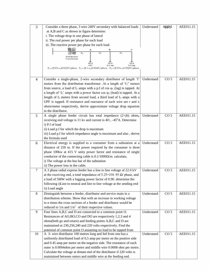
3 Consider a three phase, 3 wire 240V secondary with balanced loads
at A,B and C as shown in figure determine:
i. The voltage drop in one phase of lateral
ii. The real power per phase for each load
iii. The reactive power per phase for each load.
Apply 3
Understand CO 5 AEE011.15
4 Consider a single-phase, 2-wire secondary distributor of length ‘I’
meters from the distribution transformer .At a length of ‘I1” meters
from source, a load of I1 amps with a p.f of cos φ1 (lag) is tapped. At
a length of ‘I2’ amps with a power factor cos φ2 (lead) is tapped. At a
length of I3 meters from second load, a third load of I3 amps with a
UPF is tapped. If resistance and reactance of each wire are r and x
ohms/meter respectively, derive approximate voltage drop equation
in the distributor.
Understand CO 5 AEE011.15
5 A single phase feeder circuit has total impedance (2+j6) ohms,
receiving end voltage is 11 kv and current is 40∟-450A. Determine
i) P.f of load
ii) Load p.f for which the drop is maximum
iii) Load p.f for which impedance angle is maximum and also , derive
the formula used
Understand CO 5 AEE011.15
6 Electrical energy is supplied to a consumer from a substation at a
distance of 250 m. If the power required by the consumer is three
phase 100kw at 415 V unity power factor and resistance of single
conductor of the connecting cable is 0.1/1000Ω/m. calculate,
i) The voltage at the bus bar of the substation
ii) The power loss in the cable.
Understand CO 5 AEE011.15
7 A 3 phase radial express feeder has a line to line voltage of 22.0 kV
at the receiving end, a total impedance of 5.25+J10. 95 Ω/ phase, and
a load of 5MW with a logging power factor of 0.90. determine the
following i)Line to neutral and line to line voltage at the sending end
ii) Load angle
Understand CO 5 AEE011.15
8 Distinguish between a feeder, distributor and service main in a
distribution scheme. Show that with an increase in working voltage
to n times the cross sections of a feeder and distributor would be
reduced to 1/n and 1/n2 of their respective values.
Understand CO 5 AEE011.15
9 Four lines A,B,C and D are connected to a common point O.
Resistances of AO,BO,CO and DO are respectively 1,2,3 and 4
ohms(both go and return) and feeding points A,B,C and D are
maintained at 230,250,240 and 220 volts respectively. Find the
potential of common point O assuming no load to be tapped from
there.
Understand CO 5 AEE011.15
10 A 3- wire distributor 100 metres long and fed from one has a
uniformly distributed load of 0,5 amp per metre on the positive side
and 0.45 amp per metre on the negative side. The resistance of each
outer is 0.0004ohm per metre and middle wire 0.0008 ohm per metre.
Calculate the voltage at distant end of the distributor if 220 volts is
maintained between outers and middle wire at the feeding end.
Understand CO 5 AEE011.15

Prepared by: Ms. T Saritha Kumari, Assistant Professor
HOD, EEE
11 A 2 wire D.C distributor XY fed at end X is 500 metres long and has
a resistance of 0.1 ohm per km (go and return). At A,100 metres from
X is load at 50A; at B,200 metres further from point A there is load
of 0.5 amp/metre. Find the position of C so that maximum drop any
consumer does not exceed 4 volts.
Understand CO 5 AEE011.15