Installation Manual - Hearth N Homedownloads.hearthnhome.com/installManuals/2300_970.pdf ·...
68
1 Heat & Glo • MEZZO36, MEZZO36ST, MEZZO48, MEZZO48ST Installation Manual • 2300-970 Rev. T • 3/16 Models: Installation Manual Installation and Appliance Setup INSTALLER: Leave this manual with party responsible for use and operation. OWNER: Retain this manual for future reference. MEZZO36 MEZZO36ST MEZZO48 MEZZO48ST MEZZO60 MEZZO60ST MEZZO72 MEZZO72ST NOTICE: DO NOT discard this manual! In the Commonwealth of Massachusetts installation must be performed by a licensed plumber or gas fitter. See Table of Contents for location of additional Commonwealth of Massachusetts requirements. This appliance may be installed as an OEM installation in manufactured home (USA only) or mobile home and must be installed in accordance with the manufacturer’s instructions and the Manufactured Home Construction and Safety Standard, Title 24 CFR, Part 3280 in the United States, or the Standard for Installation in Mobile Homes, CAN/CSA Z240 MH Series, in Canada. This appliance is only for use with the type(s) of gas indicated on the rating plate. This appliance is not convertible for use with other gases, unless a certified kit is used. • DO NOT store or use gasoline or other flam- mable vapors and liquids in the vicinity of this or any other appliance. • What to do if you smell gas - DO NOT try to light any appliance. - DO NOT touch any electrical switch. DO NOT use any phone in your building. - Leave the building immediately. - Immediately call your gas supplier from a neighbor’s phone. Follow the gas sup- plier’s instructions. - If you cannot reach your gas supplier, call the fire department. • Installation and service must be performed by a qualified installer, service agency, or the gas supplier. WARNING: FIRE OR EXPLOSION HAZARD Failure to follow safety warnings exactly could result in serious injury, death, or property damage. DANGER HOT GLASS WILL CAUSE BURNS. DO NOT TOUCH GLASS UNTIL COOLED. NEVER ALLOW CHILDREN TO TOUCH GLASS. A barrier designed to reduce the risk of burns from the hot viewing glass is provided with this appliance and shall be installed for the protection of children and other at-risk individuals.
Transcript of Installation Manual - Hearth N Homedownloads.hearthnhome.com/installManuals/2300_970.pdf ·...

1Heat & Glo • MEZZO36, MEZZO36ST, MEZZO48, MEZZO48ST Installation Manual • 2300-970 Rev. T • 3/16
Models:
Installation ManualInstallation and Appliance Setup
INSTALLER: Leave this manual with party responsible for use and operation.OWNER: Retain this manual for future reference.
MEZZO36MEZZO36STMEZZO48MEZZO48STMEZZO60MEZZO60STMEZZO72MEZZO72ST
NOTICE: DO NOT discard this manual!
In the Commonwealth of Massachusetts installation must be performed by a licensed plumber or gas fi tter.See Table of Contents for location of additional Commonwealth of Massachusetts requirements.
This appliance may be installed as an OEM installation in manufactured home (USA only) or mobile home and must be installed in accordance with the manufacturer’s instructions and the Manufactured Home Construction and Safety Standard, Title 24 CFR, Part 3280 in the United States, or the Standard for Installation in Mobile Homes, CAN/CSA Z240 MH Series, in Canada.This appliance is only for use with the type(s) of gas indicated on the rating plate. This appliance is not convertible for use with other gases, unless a certifi ed kit is used.
• DO NOT store or use gasoline or other fl am-mable vapors and liquids in the vicinity of this or any other appliance.
• What to do if you smell gas - DO NOT try to light any appliance.- DO NOT touch any electrical switch. DO
NOT use any phone in your building.- Leave the building immediately.- Immediately call your gas supplier from
a neighbor’s phone. Follow the gas sup-plier’s instructions.
- If you cannot reach your gas supplier, call the fi re department.
• Installation and service must be performed by a qualifi ed installer, service agency, or the gas supplier.
WARNING: FIRE OR EXPLOSION HAZARDFailure to follow safety warnings exactly could result in serious injury, death, or property damage.
DANGERHOT GLASS WILL CAUSE BURNS.
DO NOT TOUCH GLASS UNTIL COOLED.
NEVER ALLOW CHILDREN TO TOUCH GLASS.
A barrier designed to reduce the risk of burns from the hot viewing glass is provided with this appliance and shall be installed for the protection of children and other at-risk individuals.
schumachers
retired Installation manual-split format

2Heat & Glo • MEZZO36/ST, MEZZO48/ST MEZZO60/ST, MEZZO72/ST Installation Manual • 2300-970 Rev. T • 3/16
Safety Alert Key:• DANGER! Indicates a hazardous situation which, if not avoided will result in death or serious injury.• WARNING! Indicates a hazardous situation which, if not avoided could result in death or serious injury.• CAUTION! Indicates a hazardous situation which, if not avoided, could result in minor or moderate injury.• NOTICE: Used to address practices not related to personal injury.
Table of Contents
Installation Standard Work Checklist . . . . . . . . . . . . . . . . . . . . 3
1 Product Specifi c and Important Safety Information A. Appliance Certifi cation . . . . . . . . . . . . . . . . . . . . . . . . . . . . 4B. Glass Specifi cations . . . . . . . . . . . . . . . . . . . . . . . . . . . . . . 4C. BTU Specifi cations . . . . . . . . . . . . . . . . . . . . . . . . . . . . . . . 4D. High Altitude Installations . . . . . . . . . . . . . . . . . . . . . . . . . . 4E. Non-Combustible Materials Specifi cation. . . . . . . . . . . . . . 5F. Combustible Materials Specifi cation . . . . . . . . . . . . . . . . . 5G. Electrical Codes . . . . . . . . . . . . . . . . . . . . . . . . . . . . . . . . . 5H. Requirements for the Commonwealth of Massachusetts . . 6
2 Getting Started A. Design and Installation Considerations . . . . . . . . . . . . . . . 7B. Good Faith Wall Surface/TV Guidelines . . . . . . . . . . . . . . 7C. Tools and Supplies Needed . . . . . . . . . . . . . . . . . . . . . . . . 8D. Inspect Appliance and Components . . . . . . . . . . . . . . . . . . 8
3 Framing and Clearances A. Appliance/Decorative Front Dimension Diagrams . . . . . . . 9B. Clearances to Combustibles . . . . . . . . . . . . . . . . . . . . . . 16C. Constructing the Appliance Chase . . . . . . . . . . . . . . . . . . 17D. Floor Protection . . . . . . . . . . . . . . . . . . . . . . . . . . . . . . . . 20
4 Termination Location and Vent Information A. Vent Termination Minimum Clearances . . . . . . . . . . . . . . 21B. Chimney Diagram. . . . . . . . . . . . . . . . . . . . . . . . . . . . . . . 22C. Approved Pipe . . . . . . . . . . . . . . . . . . . . . . . . . . . . . . . . . 23D. Use of Elbows . . . . . . . . . . . . . . . . . . . . . . . . . . . . . . . . . 23E. Measuring Standards . . . . . . . . . . . . . . . . . . . . . . . . . . . . 23F. Vent Diagrams . . . . . . . . . . . . . . . . . . . . . . . . . . . . . . . . . 23
5 Vent Clearances and Framing A. Pipe Clearances to Combustibles . . . . . . . . . . . . . . . . . . 31B. Wall Penetration Framing/Firestops . . . . . . . . . . . . . . . . . 31C. Install the Ceiling Firestop . . . . . . . . . . . . . . . . . . . . . . . . 32D. Install Attic Insulation Shield . . . . . . . . . . . . . . . . . . . . . . . 32E. Installing the Optional Heat-Zone® Gas Kit . . . . . . . . . . . 33
6 Appliance Preparation A. Vent Collar Preparation . . . . . . . . . . . . . . . . . . . . . . . . . . 34B. Securing and Leveling the Appliance . . . . . . . . . . . . . . . . 35
C. Installing Non-Combustible Facing Material . . . . . . . . . . 36
7 Venting and Chimneys A. Assemble Vent Sections . . . . . . . . . . . . . . . . . . . . . . . . . 37B. Assemble Slip Sections . . . . . . . . . . . . . . . . . . . . . . . . . . 38C. Secure The Vent Sections . . . . . . . . . . . . . . . . . . . . . . . . 38D. Disassemble Vent Sections . . . . . . . . . . . . . . . . . . . . . . . 39E. Vertical Termination Requirements . . . . . . . . . . . . . . . . . . 40F. Horizontal Termination Requirements . . . . . . . . . . . . . . . 41
8 Electrical Information A. General Information . . . . . . . . . . . . . . . . . . . . . . . . . . . . . 43B. Wiring Requirements . . . . . . . . . . . . . . . . . . . . . . . . . . . . 44
9 Gas Information A. Fuel Conversion . . . . . . . . . . . . . . . . . . . . . . . . . . . . . . . . 45B. Gas Pressure . . . . . . . . . . . . . . . . . . . . . . . . . . . . . . . . . . 45C. Gas Service Access . . . . . . . . . . . . . . . . . . . . . . . . . . . . . 45D. Gas Connection . . . . . . . . . . . . . . . . . . . . . . . . . . . . . . . . 47E. High Altitude Installations . . . . . . . . . . . . . . . . . . . . . . . . . 47F. Air Shutter Setting . . . . . . . . . . . . . . . . . . . . . . . . . . . . . . 48
10 Finishing A. Facing and Finishing Instructions. . . . . . . . . . . . . . . . . . . 49B. Mantel and Wall Projections . . . . . . . . . . . . . . . . . . . . . . . 56C. Decorative Front Dimensions for Finishing . . . . . . . . . . . 58
11 Appliance Setup A. Fixed Glass Assembly . . . . . . . . . . . . . . . . . . . . . . . . . . . 59B. Remove the Shipping Materials/Install Vanity Panel . . . 59C. Clean the Appliance . . . . . . . . . . . . . . . . . . . . . . . . . . . . . 59D. Install Glass Refractory Panels . . . . . . . . . . . . . . . . . . . . 59E. Install Media . . . . . . . . . . . . . . . . . . . . . . . . . . . . . . . . . . 61F. Install Log Set . . . . . . . . . . . . . . . . . . . . . . . . . . . . . . . . . 61
12 Reference Materials A. Vent Components Diagrams . . . . . . . . . . . . . . . . . . . . . . 62B. Accessories . . . . . . . . . . . . . . . . . . . . . . . . . . . . . . . . . . . 68
= Contains updated information.

3Heat & Glo • MEZZO36, MEZZO36ST, MEZZO48, MEZZO48ST Installation Manual • 2300-970 Rev. T • 3/16
Installation Standard Work Checklist
Customer: Lot/Address:
Model (circle one):MEZZO36 MEZZO48 MEZZO60 MEZZO72 MEZZO36ST MEZZO48ST MEZZO60ST MEZZO72ST
Date Installed: Location of Fireplace:Installer:Dealer/Distributor Phone # Serial #:
Comments: Further description of the issues, who is responsible (Installer/ Builder/ Other Trades, etc) and corrective action needed ______________________________________________________________________________________________________________________________________________________________________________________Comments Communicated to party responsible ____________________ by ______________________on ___________ (Builder / Gen. Contractor/) (Installer) (Date)
Appliance Install Sections 3 and 6 YES IF NO, WHY?Veri ed that the chase is insulated and sealed. (Pg. 17) ___________________________Required factory included non-combustible board is installed. (Pg 36) ___________________________Veri ed clearances to combustibles. (Pg. 16-17) ___________________________Fireplace is leveled and secured. (Pg. 35) ___________________________Pipe heat shield is attached to header. Header no wider than 3.5 in.(2x4) (Pg. 18, 19, 34) ___________________________
Venting/Chimney Sections 4,5 and 7Venting con guration complies to vent diagrams. (Pg 23-30) ___________________________Venting installed, locked, and secured in place with proper clearance. ___________________________Firestops installed. (Section 5) ___________________________Attic insulation shield installed. (Pg 32) ___________________________Exterior wall/Roof ashing installed and sealed. (Section 7) ___________________________Terminations installed and sealed. (Section 7) ___________________________
Electrical Section 8 (Pg 43-44)Unswitched power (110-120 VAC) provided to the appliance. ___________________________Switch wires properly installed. ___________________________
Gas Section 9 (Pg 45-48)Proper appliance for fuel type. ___________________________Was a conversion performed? ___________________________Leak check performed and inlet pressure veri ed. ___________________________Veri ed proper air shutter setting for installation type. ___________________________
Finishing Section 10 (Pg 49-58)Combustible materials not installed in non-combustible areas. ___________________________Veri ed all clearances meet installation manual requirements. ___________________________Finishing done correctly using inside t or overlap t method. ___________________________ Finishing template removed. ___________________________Mantels and wall projections comply with installation manual requirements. ___________________________
Appliance Setup Section 11 (Pg 59-61)All packaging and protective materials removed (inside & outside of appliance). ___________________________Refractories and media installed correctly. ___________________________Glass assembly installed and secured. ___________________________Accessories installed properly. ___________________________Decorative front properly installed. ___________________________Manual bag and all of its contents are removed from inside/under the appliance and given to party responsible for use and operation. ___________________________Started appliance and veri ed no gas leaks exist. ___________________________Lights work in all switched positions (if so equipped). ___________________________ Component heat shield is installed. (Pg. 43.) ___________________________
2300-972 Rev. E 3/16 = Contains updated information.
Hearth & Home Technologies recommends the following:• Photographing the installation and copying this checklist for your le. • That this checklist remain visible at all times on the appliance until the installation is complete.
This standard work checklist is to be used by the installer in conjunction with, not instead of, the instructions contained in this installation manual.
WARNING! Risk of Fire or Explosion! Failure to install appliance according to these instructions can lead to a re or explosion.
ATTENTION INSTALLER:Follow this Standard Work Checklist
4Heat & Glo • MEZZO36/ST, MEZZO48/ST MEZZO60/ST, MEZZO72/ST Installation Manual • 2300-970 Rev. T • 3/16
B. Glass Specifi cationsThis appliance is equipped with 5 mm ceramic glass. Re-place glass only with 5 mm ceramic glass. Please contact your dealer for replacement glass.
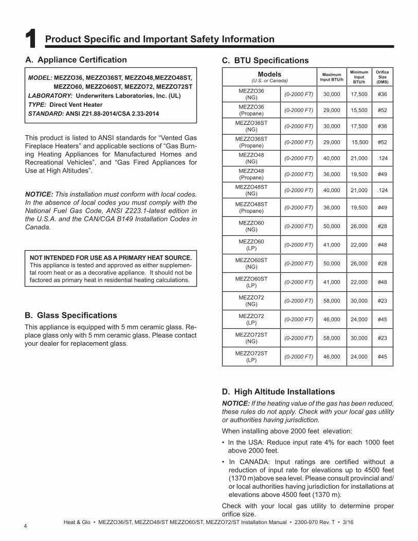
This product is listed to ANSI standards for “Vented Gas Fireplace Heaters” and applicable sections of “Gas Burn-ing Heating Appliances for Manufactured Homes and Recreational Vehicles”, and “Gas Fired Appliances for Use at High Altitudes”.
A. Appliance Certifi cation
NOT INTENDED FOR USE AS A PRIMARY HEAT SOURCE. This appliance is tested and approved as either supplemen-tal room heat or as a decorative appliance. It should not be factored as primary heat in residential heating calculations.
NOTICE: This installation must conform with local codes. In the absence of local codes you must comply with the National Fuel Gas Code, ANSI Z223.1-latest edition in the U.S.A. and the CAN/CGA B149 Installation Codes in Canada.
1 1 Product Specifi c and Important Safety Information
MODEL: MEZZO36, MEZZO36ST, MEZZO48,MEZZO48ST, MEZZO60, MEZZO60ST, MEZZO72, MEZZO72STLABORATORY: Underwriters Laboratories, Inc. (UL)TYPE: Direct Vent HeaterSTANDARD: ANSI Z21.88-2014/CSA 2.33-2014
C. BTU Specifi cations
D. High Altitude InstallationsNOTICE: If the heating value of the gas has been reduced, these rules do not apply. Check with your local gas utility or authorities having jurisdiction.When installing above 2000 feet elevation:• In the USA: Reduce input rate 4% for each 1000 feet
above 2000 feet.• In CANADA: Input ratings are certifi ed without a
reduction of input rate for elevations up to 4500 feet (1370 m)above sea level. Please consult provincial and/or local authorities having jurisdiction for installations at elevations above 4500 feet (1370 m).
Check with your local gas utility to determine proper orifi ce size.
Models(U.S. or Canada)
MaximumInput BTU/h
MinimumInput BTU/h
Orifi ceSize
(DMS)
MEZZO36(NG) (0-2000 FT) 30,000 17,500 #36
MEZZO36(Propane) (0-2000 FT) 29,000 15,500 #52
MEZZO36ST(NG) (0-2000 FT) 30,000 17,500 #36
MEZZO36ST(Propane) (0-2000 FT) 29,000 15,500 #52
MEZZO48(NG) (0-2000 FT) 40,000 21,000 .124
MEZZO48(Propane) (0-2000 FT) 36,000 19,500 #49
MEZZO48ST(NG) (0-2000 FT) 40,000 21,000 .124
MEZZO48ST(Propane) (0-2000 FT) 36,000 19,500 #49
MEZZO60(NG) (0-2000 FT) 50,000 26,000 #28
MEZZO60(LP) (0-2000 FT) 41,000 22,000 #48
MEZZO60ST(NG) (0-2000 FT) 50,000 26,000 #28
MEZZO60ST(LP) (0-2000 FT) 41,000 22,000 #48
MEZZO72(NG) (0-2000 FT) 58,000 30,000 #23
MEZZO72(LP) (0-2000 FT) 46,000 24,000 #45
MEZZO72ST(NG) (0-2000 FT) 58,000 30,000 #23
MEZZO72ST(LP) (0-2000 FT) 46,000 24,000 #45

5Heat & Glo • MEZZO36, MEZZO36ST, MEZZO48, MEZZO48ST Installation Manual • 2300-970 Rev. T • 3/16
E. Non-Combustible Materials Specifi cationMaterial which will not ignite and burn. Such materials are those consisting entirely of steel, iron, brick, tile, concrete, slate, glass or plasters, or any combination thereof.Materials that are reported as passing ASTM E 136, Standard Test Method for Behavior of Materials in a Vertical Tube Furnace at 750 ºC shall be considered non-combustible materials.
F. Combustible Materials Specifi cationMaterials made of or surfaced with wood, compressed pa-per, plant fi bers, plastics, or other material that can ignite and burn, whether fl ame proofed or not, or plastered or unplastered shall be considered combustible materials.
G. Electrical CodesNOTICE: This appliance must be electrically wired and grounded in accordance with local codes or, in the absence of local codes, with National Electric Code ANSI/NFPA 70-latest edition or the Canadian Electric Code CSA C22.1.• A 110-120 VAC circuit for this product must be pro-
tected with ground-fault circuit-interrupter protection, in compliance with the applicable electrical codes, when it is installed in locations such as in bathrooms or near sinks.

6Heat & Glo • MEZZO36/ST, MEZZO48/ST MEZZO60/ST, MEZZO72/ST Installation Manual • 2300-970 Rev. T • 3/16
H. Requirements for the Commonwealth of Massachusetts
For all side wall horizontally vented gas fueled equipment installed in every dwelling, building or structure used in whole or in part for residential purposes, including those owned or operated by the Commonwealth and where the side wall exhaust vent termination is less than seven (7) feet above fi nished grade in the area of the venting, in-cluding but not limited to decks and porches, the following requirements shall be satisfi ed:
Installation of Carbon Monoxide DetectorsAt the time of installation of the side wall horizontal vented gas fueled equipment, the installing plumber or gas fi tter shall observe that a hard wired carbon monoxide detector with an alarm and battery back-up is installed on the fl oor level where the gas equipment is to be installed. In addi-tion, the installing plumber or gas fi tter shall observe that a battery operated or hard wired carbon monoxide detec-tor with an alarm is installed on each additional level of the dwelling, building or structure served by the side wall horizontal vented gas fueled equipment. It shall be the responsibility of the property owner to secure the services of qualifi ed licensed professionals for the installation of hard wired carbon monoxide detectors.
In the event that the side wall horizontally vented gas fu-eled equipment is installed in a crawl space or an attic, the hard wired carbon monoxide detector with alarm and battery back-up may be installed on the next adjacent fl oor level.In the event that the requirements of this subdivision can not be met at the time of completion of installation, the owner shall have a period of thirty (30) days to comply with the above requirements; provided, however, that dur-ing said thirty (30) day period, a battery operated carbon monoxide detector with an alarm shall be installed.
Approved Carbon Monoxide DetectorsEach carbon monoxide detector as required in accor-dance with the above provisions shall comply with NFPA 720 and be ANSI/UL 2034 listed and IAS certifi ed.
SignageA metal or plastic identifi cation plate shall be permanent-ly mounted to the exterior of the building at a minimum height of eight (8) feet above grade directly in line with the exhaust vent terminal for the horizontally vented gas fu-eled heating appliance or equipment. The sign shall read, in print size no less than one-half (1/2) in. in size, “GAS VENT DIRECTLY BELOW. KEEP CLEAR OF ALL OB-STRUCTIONS”.
InspectionThe state or local gas inspector of the side wall horizon-tally vented gas fueled equipment shall not approve the installation unless, upon inspection, the inspector ob-serves carbon monoxide detectors and signage installed in accordance with the provisions of 248 CMR 5.08(2)(a)1 through 4.
ExemptionsThe following equipment is exempt from 248 CMR 5.08(2)(a)1 through 4: • The equipment listed in Chapter 10 entitled “Equipment
Not Required To Be Vented” in the most current edition of NFPA 54 as adopted by the Board; and
• Product Approved side wall horizontally vented gas fu-eled equipment installed in a room or structure separate from the dwelling, building or structure used in whole or in part for residential purposes.
MANUFACTURER REQUIREMENTS
Gas Equipment Venting System ProvidedWhen the manufacturer of Product Approved side wall horizontally vented gas equipment provides a venting system design or venting system components with the equipment, the instructions provided by the manufacturer for installation of the equipment and the venting system shall include:• Detailed instructions for the installation of the venting
system design or the venting system components; and• A complete parts list for the venting system design or
venting system.
Gas Equipment Venting System NOT ProvidedWhen the manufacturer of a Product Approved side wall horizontally vented gas fueled equipment does not pro-vide the parts for venting the fl ue gases, but identifi es “special venting systems”, the following requirements shall be satisfi ed by the manufacturer:
• The referenced “special venting system” instructions shall be included with the appliance or equipment in-stallation instructions; and
• The “special venting systems” shall be Product Ap-proved by the Board, and the instructions for that sys-tem shall include a parts list and detailed installation instructions.
A copy of all installation instructions for all Product Ap-proved side wall horizontally vented gas fueled equip-ment, all venting instructions, all parts lists for venting instructions, and/or all venting design instructions shall remain with the appliance or equipment at the completion of the installation.
See Gas Connection section for additional Common-wealth of Massachusetts requirements.
Note: The following requirements reference various Massachusetts and national codes not contained in this document.

7Heat & Glo • MEZZO36, MEZZO36ST, MEZZO48, MEZZO48ST Installation Manual • 2300-970 Rev. T • 3/16
2 2 Getting Started
A. Design and Installation ConsiderationsHeat & Glo direct vent gas appliances are designed to operate with all combustion air siphoned from outside of the building and all exhaust gases expelled to the outside. No additional outside air source is required.Installation MUST comply with local, regional, state and national codes and regulations. Consult insurance carrier, local building inspector, fi re offi cials or authorities having jurisdiction over restrictions, installation inspection and permits.Before installing, determine the following:• Where the appliance is to be installed.• The vent system confi guration to be used.• Gas supply piping.• Electrical wiring requirements.• Framing and fi nishing details.• Whether optional accessories—devices such as a wall
switch or remote control—are desired.
Improper installation, adjustment, alteration, service or maintenance can cause injury or property damage. For assistance or additional information, consult a qualifi ed service technician, service agency or your dealer.
Installation and service of this appliance should be performed by qualifi ed personnel. Hearth & Home Technologies recommends HHT Factory Trained or NFI certified professionals.
Figure 2.1 Good Faith Wall Surface Temperatures Above Appliance(MEZZO36/MEZZO36ST/MEZZO48/MEZZO48ST)
B. Good Faith Wall Surface/TV Guidelines
NOTICE: Temperatures listed above are taken with a temperature measuring probe as prescribed by the test standard used for appliance certifi cation. Temperatures on walls or mantels taken with an infrared thermometer may yield increased temperatures of up to 30 degrees or more depending on the thermometer settings and material characteristics being measured.
MEASUREMENTS FROMTOP EDGE OF THE OPENING
6 in.
18 in.
24 in.
30 in.
36 in.
48 in.
TO CEILING
42 in.
12 in.170°F
APPLIANCE FRONT
155°F
145°F
140°F
130°F
125°F
125°F
Figure 2.2. Good Faith Wall Surface Temperatures Above Appliance (MEZZO60/MEZZO60ST/MEZZO72/MEZZO72ST)
MEASUREMENTS FROMTOP EDGE OF THE OPENING
6 in.
18 in.
24 in.
30 in.
36 in.
48 in.
TO CEILING
42 in.
12 in.245°F
APPLIANCE FRONT
190°F
155°F
140°F
135°F
125°F
125°F

8Heat & Glo • MEZZO36/ST, MEZZO48/ST MEZZO60/ST, MEZZO72/ST Installation Manual • 2300-970 Rev. T • 3/16
D. Inspect Appliance and Components• Carefully remove the appliance and components from
the packaging. • The vent system components and decorative doors and
fronts may be shipped in separate packages. • If packaged separately, the media, refractory, and/or
optional log kits must be installed. • Report to your dealer any parts damaged in shipment,
particularly the condition of the glass. • Read all of the instructions before starting the instal-
lation. Follow these instructions carefully during the installation to ensure maximum safety and benefi t.
WARNING! Risk of Fire or Explosion! Damaged parts could impair safe operation. DO NOT install damaged, in-complete or substitute components. Keep appliance dry.
C. Tools and Supplies NeededBefore beginning the installation be sure that the following tools and building supplies are available.Tape measure Framing materialPliers Non-corrosive leak check solutionHammer Phillips screwdriverGloves Framing squareVoltmeter Electric drill and bits (1/4 in. magnetic) Plumb line Safety glassesLevel Reciprocating sawManometer Flat blade screwdriver1/2 - 3/4 in. length, #6 or #8 Self-drilling screwsCaulking material (300ºF minimum continuous exposure rating)
Hearth & Home Technologies disclaims any responsibility for, and the warranty will be voided by, the following actions:
• Installation and use of any damaged appliance or vent system component.
• Modifi cation of the appliance or vent system.
• Installation other than as instructed by Hearth & Home Technologies.
• Improper positioning of the gas logs or the glass door.
• Installation and/or use of any component part not approved by Hearth & Home Technologies.
Any such action may cause a fi re hazard.
WARNING! Risk of Fire, Explosion or Electric Shock! DO NOT use this appliance if any part has been under water. Call a qualifi ed service technician to inspect the appliance and to replace any part of the control system and/or gas control which has been under water.

9Heat & Glo • MEZZO36, MEZZO36ST, MEZZO48, MEZZO48ST Installation Manual • 2300-970 Rev. T • 3/16
3 3 Framing and Clearances
Figure 3.1 Appliance Dimensions - MEZZO36, MEZZO48
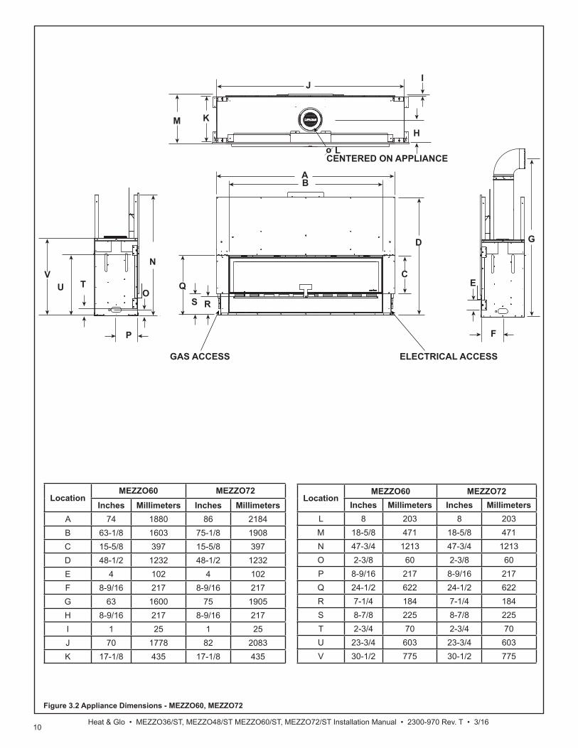
A. Appliance/Decorative Front Dimension DiagramsDimensions are actual appliance dimensions. Use for reference only. For framing dimensions and clearances refer to Section 5.
BA
CD
E
F
G
H
IJ
KM
o
N
O
P
Q
S
T
R
U
GAS ACCESS ELECTRICAL ACCESS
CENTERED ON APPLIANCEL
V
Location MEZZO36 MEZZO48
Inches Millimeters Inches MillimetersA 50 1270 62 1575B 39-1/4 997 51-1/8 1299C 15-5/8 397 15-5/8 397D 42-1/2 1080 42-1/2 1080E 4 102 4 102F 8-9/16 217 8-9/16 217G 63 1600 63 1600H 8-9/16 217 8-9/16 217I 1 25 1 25J 46-3/16 1173 58 1473K 17-1/8 435 17-1/8 435
Location MEZZO36 MEZZO48
Inches Millimeters Inches MillimetersL 8 203 8 203M 18-5/8 471 18-5/8 471N 41-3/4 1060 41-3/4 1060O 2-3/8 60 2-3/8 60P 8-9/16 217 8-9/16 217Q 24-1/2 622 24-1/2 622R 7-1/4 184 7-1/4 184S 8-7/8 225 8-7/8 225T 2-3/4 70 2-3/4 70U 23-3/4 603 23-3/4 603V 30-1/2 775 30-1/2 775
10Heat & Glo • MEZZO36/ST, MEZZO48/ST MEZZO60/ST, MEZZO72/ST Installation Manual • 2300-970 Rev. T • 3/16
Location MEZZO60 MEZZO72
Inches Millimeters Inches MillimetersA 74 1880 86 2184B 63-1/8 1603 75-1/8 1908C 15-5/8 397 15-5/8 397D 48-1/2 1232 48-1/2 1232E 4 102 4 102F 8-9/16 217 8-9/16 217G 63 1600 75 1905H 8-9/16 217 8-9/16 217I 1 25 1 25J 70 1778 82 2083K 17-1/8 435 17-1/8 435
Location MEZZO60 MEZZO72
Inches Millimeters Inches MillimetersL 8 203 8 203M 18-5/8 471 18-5/8 471N 47-3/4 1213 47-3/4 1213O 2-3/8 60 2-3/8 60P 8-9/16 217 8-9/16 217Q 24-1/2 622 24-1/2 622R 7-1/4 184 7-1/4 184S 8-7/8 225 8-7/8 225T 2-3/4 70 2-3/4 70U 23-3/4 603 23-3/4 603V 30-1/2 775 30-1/2 775
Figure 3.2 Appliance Dimensions - MEZZO60, MEZZO72
BA
C
D
E
F
G
H
IJ
KM
o
N
O
P
QS
T
R
U
GAS ACCESS ELECTRICAL ACCESS
CENTERED ON APPLIANCEL
V
11Heat & Glo • MEZZO36, MEZZO36ST, MEZZO48, MEZZO48ST Installation Manual • 2300-970 Rev. T • 3/16
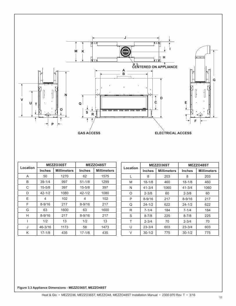
Figure 3.3 Appliance Dimensions - MEZZO36ST, MEZZO48ST
Location MEZZO36ST MEZZO48ST
Inches Millimeters Inches MillimetersA 50 1270 62 1575B 39-1/4 997 51-1/8 1299C 15-5/8 397 15-5/8 397D 42-1/2 1080 42-1/2 1080E 4 102 4 102F 8-9/16 217 8-9/16 217G 63 1600 63 1600H 8-9/16 217 8-9/16 217I 1/2 13 1/2 13
J 46-3/16 1173 58 1473K 17-1/8 435 17-1/8 435
Location MEZZO36ST MEZZO48ST
Inches Millimeters Inches MillimetersL 8 203 8 203M 18-1/8 460 18-1/8 460N 41-3/4 1060 41-3/4 1060O 2-3/8 60 2-3/8 60P 8-9/16 217 8-9/16 217Q 24-1/2 622 24-1/2 622R 7-1/4 184 7-1/4 184S 8-7/8 225 8-7/8 225T 2-3/4 70 2-3/4 70U 23-3/4 603 23-3/4 603V 30-1/2 775 30-1/2 775
G
KIM
o
O
P
Q
BA
CD
E
S
T
R
H
F
J
L
N
U
GAS ACCESS ELECTRICAL ACCESS
CENTERED ON APPLIANCE
V

12Heat & Glo • MEZZO36/ST, MEZZO48/ST MEZZO60/ST, MEZZO72/ST Installation Manual • 2300-970 Rev. T • 3/16
Figure 3.4 Appliance Dimensions - MEZZO60ST, MEZZO72ST
Location MEZZO60ST MEZZO72ST
Inches Millimeters Inches MillimetersA 74 1880 86 2184B 63-1/8 1603 75-1/8 1908C 15-5/8 397 15-5/8 397D 48-1/2 1232 48-1/2 1232E 4 102 4 102F 8-9/16 217 8-9/16 217G 63 1600 75 1905H 8-9/16 217 8-9/16 217I 1/2 13 1/2 13J 70 1778 82 2083K 17-1/8 435 17-1/8 435
Location MEZZO60ST MEZZO72ST
Inches Millimeters Inches MillimetersL 8 203 8 203M 18-1/8 460 18-1/8 460N 47-3/4 1213 47-3/4 1213O 2-3/8 60 2-3/8 60P 8-9/16 217 8-9/16 217Q 24-1/2 622 24-1/2 622R 7-1/4 184 7-1/4 184S 8-7/8 225 8-7/8 225T 2-3/4 70 2-3/4 70U 23-3/4 603 23-3/4 603V 30-1/2 775 30-1/2 775
O
P
QU
KI
M
o
J
L
N
G
H
F
BA
C
D
E
S
T
R
GAS ACCESS ELECTRICAL ACCESS
V
13Heat & Glo • MEZZO36, MEZZO36ST, MEZZO48, MEZZO48ST Installation Manual • 2300-970 Rev. T • 3/16
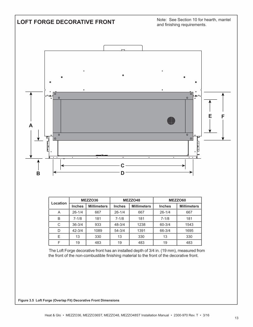
Figure 3.5 Loft Forge (Overlap Fit) Decorative Front Dimensions
LOFT FORGE DECORATIVE FRONT
A
BCD
E F
Location MEZZO36 MEZZO48 MEZZO60
Inches Millimeters Inches Millimeters Inches MillimetersA 26-1/4 667 26-1/4 667 26-1/4 667
B 7-1/8 181 7-1/8 181 7-1/8 181C 36-3/4 933 48-3/4 1238 60-3/4 1543D 42-3/4 1089 54-3/4 1391 66-3/4 1695E 13 330 13 330 13 330F 19 483 19 483 19 483
Note: See Section 10 for hearth, mantel and fi nishing requirements.
The Loft Forge decorative front has an installed depth of 3/4 in. (19 mm), measured from the front of the non-combustible fi nishing material to the front of the decorative front.
14Heat & Glo • MEZZO36/ST, MEZZO48/ST MEZZO60/ST, MEZZO72/ST Installation Manual • 2300-970 Rev. T • 3/16
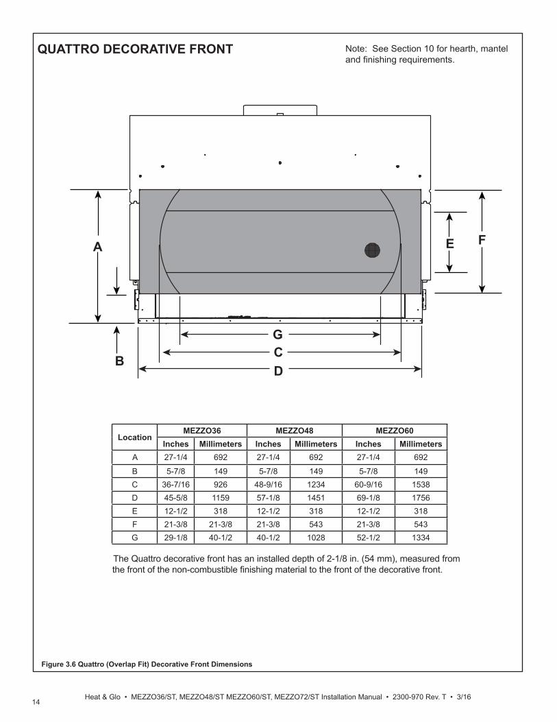
Figure 3.6 Quattro (Overlap Fit) Decorative Front Dimensions
QUATTRO DECORATIVE FRONT
A
B CD
E F
G
Location MEZZO36 MEZZO48 MEZZO60
Inches Millimeters Inches Millimeters Inches MillimetersA 27-1/4 692 27-1/4 692 27-1/4 692
B 5-7/8 149 5-7/8 149 5-7/8 149C 36-7/16 926 48-9/16 1234 60-9/16 1538D 45-5/8 1159 57-1/8 1451 69-1/8 1756E 12-1/2 318 12-1/2 318 12-1/2 318F 21-3/8 21-3/8 21-3/8 543 21-3/8 543G 29-1/8 40-1/2 40-1/2 1028 52-1/2 1334
Note: See Section 10 for hearth, mantel and fi nishing requirements.
The Quattro decorative front has an installed depth of 2-1/8 in. (54 mm), measured from the front of the non-combustible fi nishing material to the front of the decorative front.

15Heat & Glo • MEZZO36, MEZZO36ST, MEZZO48, MEZZO48ST Installation Manual • 2300-970 Rev. T • 3/16
Figure 3.7 Clean Face Trim Front (Inside Fit) Decorative Front Dimensions
CLEAN FACE TRIM DECORATIVE FRONT
Location MEZZO36 MEZZO48 MEZZO60 MEZZO72
Inches Millimeters Inches Millimeters Inches Millimeters Inches MillimetersA 39 991 51 1295 63 1600 75 1905
B 16-3/4 425 16-3/4 425 16-3/4 425 16-3/4 425C 13-1/8 333 13-1/8 333 13-1/8 333 13-1/8 333D 37-3/16 945 49-3/16 1249 61-3/16 1554 73-3/16 1859E 40-5/16 1024 52-5/16 1329 64-5/16 1634 76-5/16 1938F 24 610 24 610 24 610 24 610G 5/8 16 5/8 16 5/8 16 5/8 16H 25 635 25 635 25 635 25 635
HF
C
B
E
A
D
G
Note: See Section 10 for hearth, mantel and fi nishing requirements.
16Heat & Glo • MEZZO36/ST, MEZZO48/ST MEZZO60/ST, MEZZO72/ST Installation Manual • 2300-970 Rev. T • 3/16
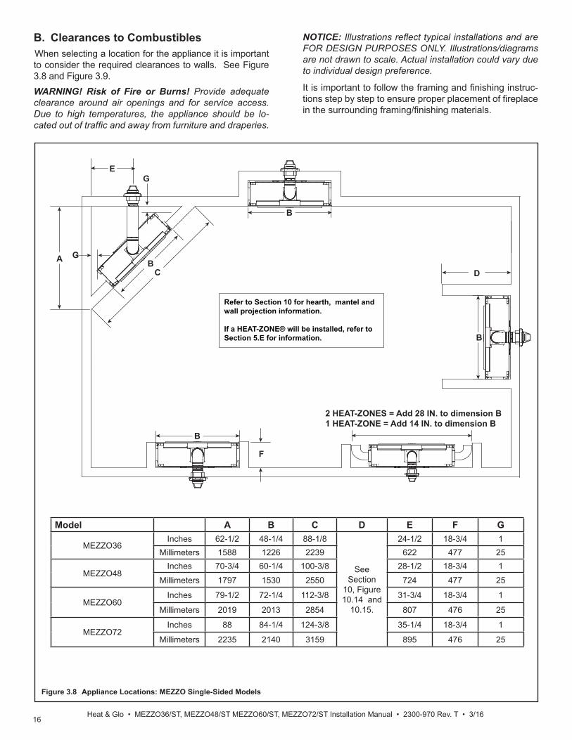
B. Clearances to CombustiblesWhen selecting a location for the appliance it is important to consider the required clearances to walls. See Figure 3.8 and Figure 3.9.WARNING! Risk of Fire or Burns! Provide adequate clearance around air openings and for service access. Due to high temperatures, the appliance should be lo-cated out of traffi c and away from furniture and draperies.
NOTICE: Illustrations refl ect typical installations and are FOR DESIGN PURPOSES ONLY. Illustrations/diagrams are not drawn to scale. Actual installation could vary due to individual design preference.
Figure 3.8 Appliance Locations: MEZZO Single-Sided Models
Model A B C D E F G
MEZZO36Inches 62-1/2 48-1/4 88-1/8
See Section
10, Figure 10.14 and
10.15.
24-1/2 18-3/4 1Millimeters 1588 1226 2239 622 477 25
MEZZO48Inches 70-3/4 60-1/4 100-3/8 28-1/2 18-3/4 1
Millimeters 1797 1530 2550 724 477 25
MEZZO60Inches 79-1/2 72-1/4 112-3/8 31-3/4 18-3/4 1
Millimeters 2019 2013 2854 807 476 25
MEZZO72Inches 88 84-1/4 124-3/8 35-1/4 18-3/4 1
Millimeters 2235 2140 3159 895 476 25
It is important to follow the framing and fi nishing instruc-tions step by step to ensure proper placement of fi replace in the surrounding framing/fi nishing materials.
B
CA B
G
B
F
E
B
G
D
Refer to Section 10 for hearth, mantel and wall projection information.
If a HEAT-ZONE® will be installed, refer to Section 5.E for information.
2 HEAT-ZONES = Add 28 IN. to dimension B1 HEAT-ZONE = Add 14 IN. to dimension B
17Heat & Glo • MEZZO36, MEZZO36ST, MEZZO48, MEZZO48ST Installation Manual • 2300-970 Rev. T • 3/16
CC
B
A
D
D
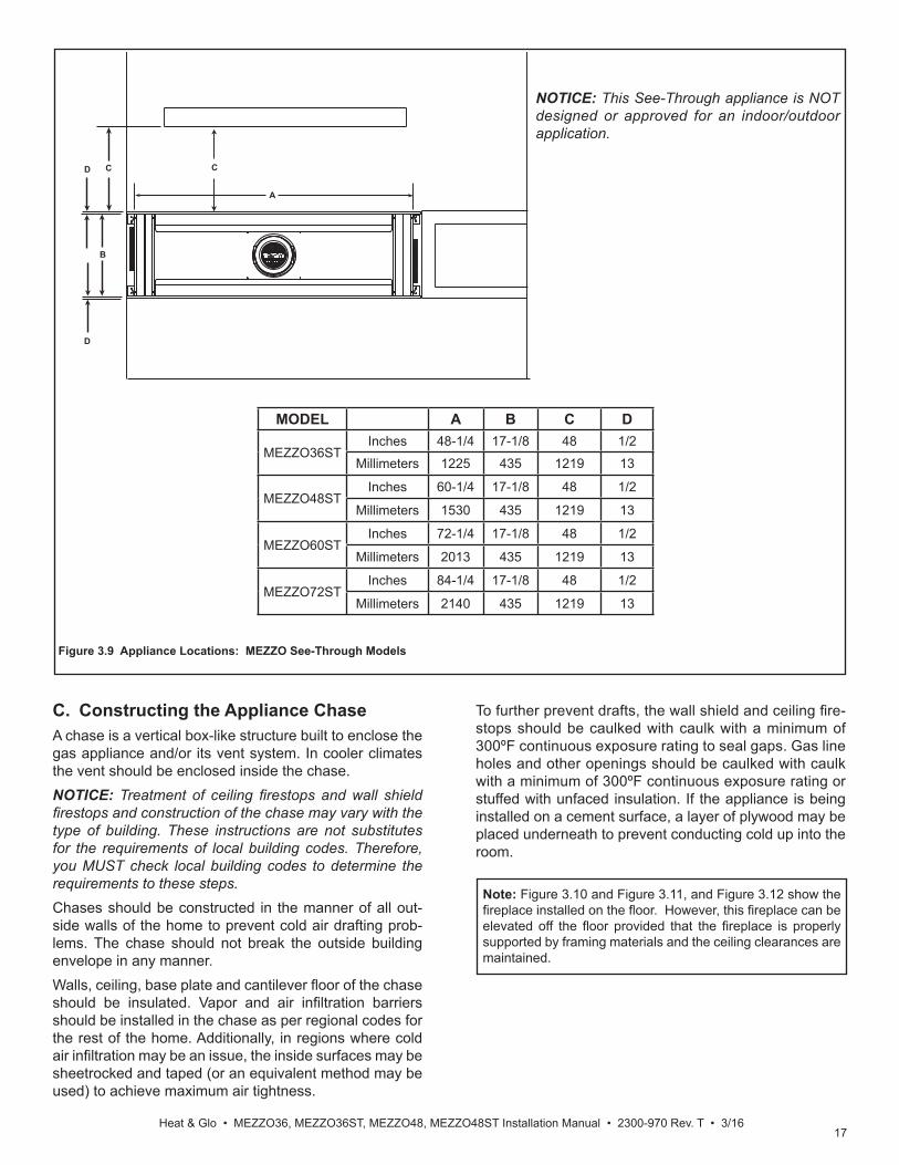
Figure 3.9 Appliance Locations: MEZZO See-Through Models
C. Constructing the Appliance ChaseA chase is a vertical box-like structure built to enclose the gas appliance and/or its vent system. In cooler climates the vent should be enclosed inside the chase.NOTICE: Treatment of ceiling fi restops and wall shield fi restops and construction of the chase may vary with the type of building. These instructions are not substitutes for the requirements of local building codes. Therefore, you MUST check local building codes to determine the requirements to these steps.Chases should be constructed in the manner of all out-side walls of the home to prevent cold air drafting prob-lems. The chase should not break the outside building envelope in any manner.Walls, ceiling, base plate and cantilever fl oor of the chase should be insulated. Vapor and air infi ltration barriers should be installed in the chase as per regional codes for the rest of the home. Additionally, in regions where cold air infi ltration may be an issue, the inside surfaces may be sheetrocked and taped (or an equivalent method may be used) to achieve maximum air tightness.
NOTICE: This See-Through appliance is NOT designed or approved for an indoor/outdoor application.
To further prevent drafts, the wall shield and ceiling fi re-stops should be caulked with caulk with a minimum of 300ºF continuous exposure rating to seal gaps. Gas line holes and other openings should be caulked with caulk with a minimum of 300ºF continuous exposure rating or stuffed with unfaced insulation. If the appliance is being installed on a cement surface, a layer of plywood may be placed underneath to prevent conducting cold up into the room.
MODEL A B C D
MEZZO36STInches 48-1/4 17-1/8 48 1/2
Millimeters 1225 435 1219 13
MEZZO48STInches 60-1/4 17-1/8 48 1/2
Millimeters 1530 435 1219 13
MEZZO60STInches 72-1/4 17-1/8 48 1/2
Millimeters 2013 435 1219 13
MEZZO72STInches 84-1/4 17-1/8 48 1/2
Millimeters 2140 435 1219 13
Note: Figure 3.10 and Figure 3.11, and Figure 3.12 show the fi replace installed on the fl oor. However, this fi replace can be elevated off the fl oor provided that the fi replace is properly supported by framing materials and the ceiling clearances are maintained.

18Heat & Glo • MEZZO36/ST, MEZZO48/ST MEZZO60/ST, MEZZO72/ST Installation Manual • 2300-970 Rev. T • 3/16
B
D
A
HEADERDEPTH**
C
APPLIANCE MAY BE INSTALLED OFF OF FLOOR***
Figure 3.10 Clearances to Combustibles-MEZZO36, MEZZO48, MEZZO60, MEZZO72
MINIMUM FRAMING DIMENSIONS*
MEZZO48A B C D E F G H I J K
RoughOpening
(Vent Pipe)
RoughOpening(Height)
RoughOpening(Depth)
RoughOpening(Width)
Clearanceto Ceiling
CombustibleFloor
CombustibleFlooring
BehindAppliance
Sides ofAppliance
Front ofAppliance
Clearance to Ceiling
Inches 10 42 18-1/4 60-1/4 31 0 0 1 1 48 55-1/2
Millimeters 254 1067 464 1530 787 0 0 25 25 1219 1410
J
G
I
H
EF
K
E=MEASUREMENT FROM TOP OF FIREPLACE OPENING TO CEILING
K=MEASUREMENT FROM BOTTOM OF FIREPLACE TO CEILING
MINIMUM FRAMING DIMENSIONS*
MEZZO36A B C D E F G H I J K
RoughOpening
(Vent Pipe)
RoughOpening(Height)
RoughOpening(Depth)
RoughOpening(Width)
Clearanceto Ceiling
CombustibleFloor
CombustibleFlooring
BehindAppliance
Sides ofAppliance
Front ofAppliance
Clearance to Ceiling
Inches 10 42 18-1/4 48-1/4 31 0 0 1 1 48 55-1/2
Millimeters 254 1067 464 1226 787 0 0 25 25 1219 1410
MINIMUM FRAMING DIMENSIONS*
MEZZO60A B C D E F G H I J K
RoughOpening
(Vent Pipe)
RoughOpening(Height)
RoughOpening(Depth)
RoughOpening(Width)
Clearanceto Ceiling
CombustibleFloor
CombustibleFlooring
BehindAppliance
Sides ofAppliance
Front ofAppliance
Clearance to Ceiling
Inches 10 48 18-1/4 72-1/4 31 0 0 1 1 48 55-1/2
Millimeters 254 1219 464 1835 787 0 0 25 25 1219 1410
MINIMUM FRAMING DIMENSIONS*
MEZZO72A B C D E F G H I J K
RoughOpening
(Vent Pipe)
RoughOpening(Height)
RoughOpening(Depth)
RoughOpening(Width)
Clearanceto Ceiling
CombustibleFloor
CombustibleFlooring
BehindAppliance
Sides ofAppliance
Front ofAppliance
Clearance to Ceiling
Inches 10 48 18-1/4 84-1/4 31 0 0 1 1 48 55-1/2
Millimeters 254 1219 464 2140 787 0 0 25 25 1219 1410
* = Adjust framing dimensions for interior sheathing (such as sheetrock)**= Header depth not to exceed 3-1/2 inches.***= If appliance is installed off of fl oor, maintain required clearances to combustibles. Construct platform in accordance with local building codes.
19Heat & Glo • MEZZO36, MEZZO36ST, MEZZO48, MEZZO48ST Installation Manual • 2300-970 Rev. T • 3/16
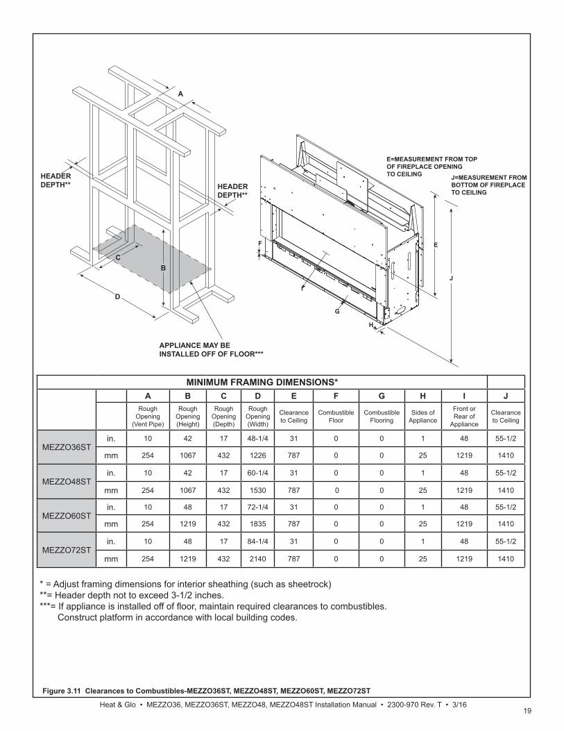
Figure 3.11 Clearances to Combustibles-MEZZO36ST, MEZZO48ST, MEZZO60ST, MEZZO72ST
MINIMUM FRAMING DIMENSIONS*A B C D E F G H I J
RoughOpening
(Vent Pipe)
RoughOpening(Height)
RoughOpening(Depth)
RoughOpening(Width)
Clearanceto Ceiling
CombustibleFloor
CombustibleFlooring
Sides ofAppliance
Front or Rear of
Appliance
Clearance to Ceiling
MEZZO36STin. 10 42 17 48-1/4 31 0 0 1 48 55-1/2
mm 254 1067 432 1226 787 0 0 25 1219 1410
MEZZO48STin. 10 42 17 60-1/4 31 0 0 1 48 55-1/2
mm 254 1067 432 1530 787 0 0 25 1219 1410
MEZZO60STin. 10 48 17 72-1/4 31 0 0 1 48 55-1/2
mm 254 1219 432 1835 787 0 0 25 1219 1410
MEZZO72STin. 10 48 17 84-1/4 31 0 0 1 48 55-1/2
mm 254 1219 432 2140 787 0 0 25 1219 1410
F
G
H
E
IJ
E=MEASUREMENT FROM TOP OF FIREPLACE OPENING TO CEILING J=MEASUREMENT FROM
BOTTOM OF FIREPLACE TO CEILING
C
A
B
D
HEADERDEPTH** HEADER
DEPTH**
APPLIANCE MAY BE INSTALLED OFF OF FLOOR***
* = Adjust framing dimensions for interior sheathing (such as sheetrock)**= Header depth not to exceed 3-1/2 inches.***= If appliance is installed off of fl oor, maintain required clearances to combustibles. Construct platform in accordance with local building codes.
20Heat & Glo • MEZZO36/ST, MEZZO48/ST MEZZO60/ST, MEZZO72/ST Installation Manual • 2300-970 Rev. T • 3/16
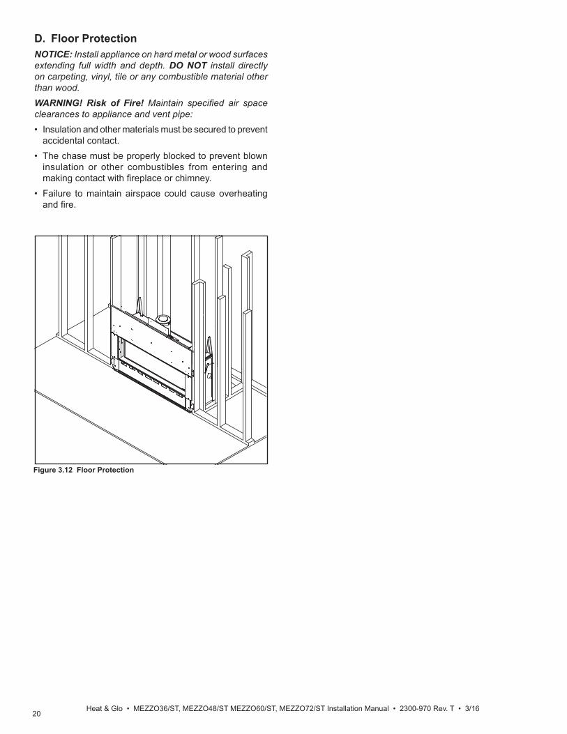
D. Floor ProtectionNOTICE: Install appliance on hard metal or wood surfaces extending full width and depth. DO NOT install directly on carpeting, vinyl, tile or any combustible material other than wood.WARNING! Risk of Fire! Maintain specifi ed air space clearances to appliance and vent pipe:• Insulation and other materials must be secured to prevent
accidental contact.• The chase must be properly blocked to prevent blown
insulation or other combustibles from entering and making contact with fi replace or chimney.
• Failure to maintain airspace could cause overheating and fi re.
Figure 3.12 Floor Protection
21Heat & Glo • MEZZO36, MEZZO36ST, MEZZO48, MEZZO48ST Installation Manual • 2300-970 Rev. T • 3/16
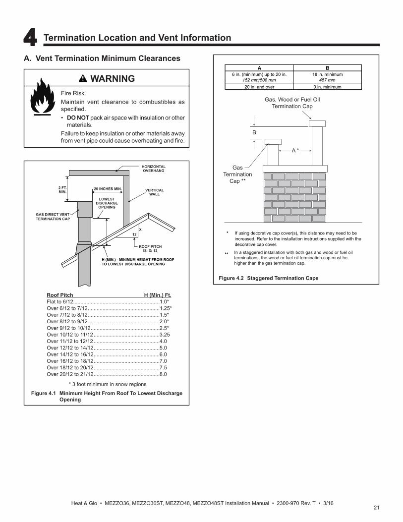
A. Vent Termination Minimum Clearances
Roof Pitch H (Min.) Ft.Flat to 6/12...........................................................1.0*Over 6/12 to 7/12 .................................................1.25*Over 7/12 to 8/12 .................................................1.5*Over 8/12 to 9/12 .................................................2.0*Over 9/12 to 10/12 ...............................................2.5*Over 10/12 to 11/12 .............................................3.25Over 11/12 to 12/12 .............................................4.0Over 12/12 to 14/12 .............................................5.0Over 14/12 to 16/12 .............................................6.0Over 16/12 to 18/12 .............................................7.0Over 18/12 to 20/12 .............................................7.5Over 20/12 to 21/12 .............................................8.0
Figure 4.1 Minimum Height From Roof To Lowest Discharge Opening
* 3 foot minimum in snow regions
HORIZONTALOVERHANG
VERTICALWALL
GAS DIRECT VENT TERMINATION CAP
12X
ROOF PITCHIS X/ 12
LOWEST DISCHARGE
OPENING
2 FT.MIN.
20 INCHES MIN.
H (MIN.) - MINIMUM HEIGHT FROM ROOFTO LOWEST DISCHARGE OPENING
4 4 Termination Location and Vent Information
Fire Risk.Maintain vent clearance to combustibles as specifi ed.• DO NOT pack air space with insulation or other
materials.Failure to keep insulation or other materials away from vent pipe could cause overheating and fi re.
WARNING
Figure 4.2 Staggered Termination Caps
Gas, Wood or Fuel OilTermination Cap
B
GasTermination
Cap **
A *
* If using decorative cap cover(s), this distance may need to be increased. Refer to the installation instructions supplied with the decorative cap cover.
**
A B6 in. (minimum) up to 20 in.
152 mm/508 mm18 in. minimum
457 mm20 in. and over 0 in. minimum
In a staggered installation with both gas and wood or fuel oil terminations, the wood or fuel oil termination cap must be higher than the gas termination cap.
22Heat & Glo • MEZZO36/ST, MEZZO48/ST MEZZO60/ST, MEZZO72/ST Installation Manual • 2300-970 Rev. T • 3/16
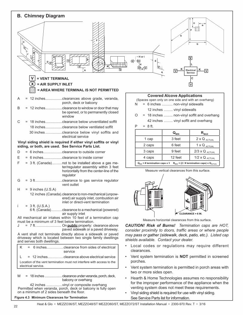
B. Chimney Diagram
Figure 4.3 Minimum Clearances for Termination
ON
P
R
Q
X = AIR SUPPLY INLET
A = 12 inches.................clearances above grade, veranda, porch, deck or balcony
B = 12 inches.................clearance to window or door that may be opened, or to permanently closed window
C = 18 inches.................clearance below unventilated soffi t 18 inches.................clearance below ventilated soffi t 30 inches .................clearance below vinyl soffits and
electrical service Vinyl siding shield is required if either vinyl soffi ts or vinyl siding, or both, are used. See Service Parts List.D = 6 inches...................clearance to outside cornerE = 6 inches...................clearance to inside cornerF = 3 ft. (Canada) ..........not to be installed above a gas me-
ter/regulator assembly within 3 feet horizontally from the center-line of the regulator
G = 3 ft ...........................clearance to gas service regulator vent outlet
H = 9 inches (U.S.A) 12 inches (Canada). clearance to non-mechanical (unpow-
ered) air supply inlet, combustion air inlet or direct-vent termination
i = 3 ft. (U.S.A.) 6 ft. (Canada) ...........clearance to a mechanical (powered)
air supply inletAll mechanical air intakes within 10 feet of a termination cap must be a minimum of 3 feet below termination.J = 7 ft. ......................... On public property: clearance above
paved sidewalk or a paved driveway.A vent shall not terminate directly above a sidewalk or paved driveway which is located between two single family dwellings and serves both dwellings.
V = VENT TERMINAL
= AREA WHERE TERMINAL IS NOT PERMITTED
C
J B
D
B
F
B
A
EV
V
VV
V
V
M
H or i
VG
X
V HA
VV
H
Electrical Service
V
KV K
V
L
C
V
N = 6 inches ........... non-vinyl sidewalls 12 inches ......... vinyl sidewallsO = 18 inches ......... non-vinyl soffi t and overhang 42 inches ......... vinyl soffi t and overhangP = 8 ft.
QMIN RMAX
1 cap 3 feet 2 x Q ACTUAL
2 caps 6 feet 1 x Q ACTUAL
3 caps 9 feet 2/3 x Q ACTUAL
4 caps 12 feet 1/2 x Q ACTUAL
QMIN = # termination caps x 3 RMAX = (2 / # termination caps) x QACTUAL
Covered Alcove Applications (Spaces open only on one side and with an overhang)
Measure horizontal clearances from this surface.
Measure vertical clearances from this surface.
CLEARANCE = 6 IN.
CAUTION! Risk of Burns! Termination caps are HOT, consider proximity to doors, traffi c areas or where people may pass or gather (sidewalk, deck, patio, etc.). Listed cap shields available. Contact your dealer.• Local codes or regulations may require different
clearances.• Vent system termination is NOT permitted in screened
porches.• Vent system termination is permitted in porch areas with
two or more sides open. • Hearth & Home Technologies assumes no responsibility
for the improper performance of the appliance when the venting system does not meet these requirements.
• Vinyl siding shield is required for use with vinyl siding. See Service Parts list for information.
M = 18 inches ....................clearance under veranda, porch, deck, balcony or overhang
42 inches ................vinyl or composite overhangPermitted when veranda, porch, deck or balcony is fully open on a minimum of 2 sides beneath the fl oor.
K = 6 inches................. clearance from sides of electrical service
L = 12 inches................ clearance above electrical serviceLocation of the vent termination must not interfere with access to the electrical service.

23Heat & Glo • MEZZO36, MEZZO36ST, MEZZO48, MEZZO48ST Installation Manual • 2300-970 Rev. T • 3/16
E. Measuring StandardsVertical and horizontal measurements listed in the vent diagrams were made using the following standards:• Pipe measurements are shown using the effective length
of pipe. See Section 12.A for information on effective length of pipe components.
• Measurements are made from the appliance outer wrap, not from the standoffs.
• Horizontal terminations are measured to the outside mounting surface (flange of termination cap). See Figure 4.3.
• Vertical terminations are measured to bottom of termination cap.
• Horizontal pipe installed level with no rise.
General Rules:• When penetrating a combustible wall, a wall shield fi restop must be installed.
• When penetrating a combustible ceiling, a ceiling fi restop must be installed.
• Horizontal runs of vent do not require vertical rise; horizontal runs may be level.
• Horizontal termination cap should have a 1/4 inch downward slant to allow any moisture in cap to be released.
F. Vent Diagrams
C. Approved PipeThis appliance is approved for use with Hearth & Home Technologies DVP venting systems. Refer to Section 12.A for vent component information and dimensions.DO NOT mix pipe, fi ttings or joining methods from differ-ent manufacturers.The pipe is tested to be run inside an enclosed wall. There is no requirement for inspection openings at each joint within the wall.WARNING! Risk of Fire or Asphyxiation. This appli-ance requires a separate vent. DO NOT vent to a pipe serving a separate solid fuel burning appliance.
D. Use of ElbowsDiagonal runs have both vertical and horizontal vent as-pects when calculating the effects. Use the rise for the vertical aspect and the run for the horizontal aspect (see Figure 4.4).Two 45º elbows may be used in place of one 90º elbow. On 45º runs, one foot of diagonal is equal to 8-1/2 in. (216 mm) horizontal run and 8-1/2 in. (216 mm) vertical run. A length of straight pipe is allowed between two 45º elbows. See Figure 4.4.
Figure 4.4
Horizontal
Vertical
8-1/2 in.
12 in
.
8-1/
2 in
.

24Heat & Glo • MEZZO36/ST, MEZZO48/ST MEZZO60/ST, MEZZO72/ST Installation Manual • 2300-970 Rev. T • 3/16
Figure 4.5
Top Vent - Horizontal Termination Venting with 1 elbow
H1 V1
Fire Risk. Explosion Risk.Do NOT pack insulation or other combustibles between ceiling fi restops.• ALWAYS maintain specifi ed clearances around venting and fi restop systems.• Install wall shield and ceiling fi restops as specifi ed.Failure to keep insulation or other material away from vent pipe could cause fi re.
WARNING
Note: Use DVP Series components only.
MEZZO36, MEZZO48, MEZZO60
V1 Minimum H1 Maximum2 ft. 610 mm 1.5 ft. 457 mm3 ft. 914 mm 6 ft. 1.8 m4 ft. 1.2 m 9 ft. 2.7 m5 ft. 1.5 m 12 ft. 3.7 m6 ft. 1.8 m 15 ft. 4.6 m7 ft. 2.1 m 18 ft. 5.5 m8 ft. 2.4 m 21 ft. 6.4 m
V1 + H1 = 63 ft. (19.2 m) MaximumH1 = 40 ft. (12.2 m) Maximum
WARNING! Risk of Fire! DO NOT attach elbow directly to the appliance. • The MEZZO36/MEZZO36ST, MEZZO48/MEZZO48ST and MEZZO60/MEZZO60ST require a minimum of 24 inches of
vertical venting before attaching any elbow to the appliance.• The MEZZO72/MEZZO72ST requires a minimum of 36 inches of vertical venting before attaching any elbow to the appliance.
MEZZO72ST
V1 Minimum H1 Maximum3 ft. 914 mm 3-1/2 ft. 1.1 m4 ft. 1.2 m 6 ft. 1.8 m5 ft. 1.5 m 9 ft. 2.7 m6 ft. 1.8 m 12 ft. 3.7 m7 ft. 2.1 m 15 ft. 4.6 m8 ft. 2.4 m 18 ft. 5.5 m9 ft. 2.7 m 21 ft 6.4 m
V1 + H1 = 63 ft. (19.2 m) MaximumH1 = 40 ft. (12.2 m) Maximum
MEZZO36ST, MEZZO48ST, MEZZO60ST
V1 Minimum H1 Maximum2 ft. 610 mm 3 ft. 914 mm3 ft. 914 mm 6 ft. 1.8 m4 ft. 1.2 m 9 ft. 2.7 m5 ft. 1.5 m 12 ft. 3.7 m6 ft. 1.8 m 15 ft. 4.6 m7 ft. 2.1 m 18 ft. 5.5 m8 ft. 2.4 m 21 ft. 6.4 m
V1 + H1 = 63 ft. (19.2 m) MaximumH1 = 40 ft. (12.2 m) Maximum
MEZZO72
V1 Minimum H1 Maximum3 ft. 914 mm 1-1/2 ft. 457 mm4 ft. 1.2 m 6 ft. 1.8 m5 ft. 1.5 m 9 ft. 2.7 m6 ft. 1.8 m 12 ft. 3.7 m7 ft. 2.1 m 15 ft. 4.6 m8 ft. 2.4 m 18 ft. 5.5 m9 ft. 2.7 m 21 ft 6.4 m
V1 + H1 = 63 ft. (19.2 m) MaximumH1 = 40 ft. (12.2 m) Maximum
25Heat & Glo • MEZZO36, MEZZO36ST, MEZZO48, MEZZO48ST Installation Manual • 2300-970 Rev. T • 3/16
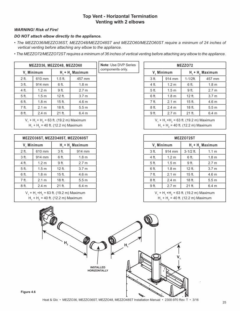
Figure 4.6
Top Vent - Horizontal TerminationVenting with 2 elbows
Note: Use DVP Series components only.
MEZZO36, MEZZO48, MEZZO60
V1 Minimum H1 + H2 Maximum2 ft. 610 mm 1.5 ft. 457 mm3 ft. 914 mm 6 ft. 1.8 m4 ft. 1.2 m 9 ft. 2.7 m5 ft. 1.5 m 12 ft. 3.7 m6 ft. 1.8 m 15 ft. 4.6 m7 ft. 2.1 m 18 ft. 5.5 m8 ft. 2.4 m 21 ft. 6.4 m
V1 + H1 + H2 = 63 ft. (19.2 m) MaximumH1 + H2 = 40 ft. (12.2 m) Maximum
INSTALLEDHORIZONTALLY
H1H2
V1
MEZZO36ST, MEZZO48ST, MEZZO60ST
V1 Minimum H1 + H2 Maximum2 ft. 610 mm 3 ft. 914 mm3 ft. 914 mm 6 ft. 1.8 m4 ft. 1.2 m 9 ft. 2.7 m5 ft. 1.5 m 12 ft. 3.7 m6 ft. 1.8 m 15 ft. 4.6 m7 ft. 2.1 m 18 ft. 5.5 m8 ft. 2.4 m 21 ft. 6.4 m
V1 + H1 +H2 = 63 ft. (19.2 m) MaximumH1 + H2 = 40 ft. (12.2 m) Maximum
MEZZO72ST
V1 Minimum H1 + H2 Maximum3 ft. 914 mm 3-1/2 ft. 1.1 m4 ft. 1.2 m 6 ft. 1.8 m5 ft. 1.5 m 9 ft. 2.7 m6 ft. 1.8 m 12 ft. 3.7 m7 ft. 2.1 m 15 ft. 4.6 m8 ft. 2.4 m 18 ft. 5.5 m9 ft. 2.7 m 21 ft. 6.4 m
V1 + H1 +H2 = 63 ft. (19.2 m) MaximumH1 + H2 = 40 ft. (12.2 m) Maximum
MEZZO72
V1 Minimum H1 + H2 Maximum3 ft. 914 mm 1-1/2ft. 457 mm4 ft. 1.2 m 6 ft. 1.8 m5 ft. 1.5 m 9 ft. 2.7 m6 ft. 1.8 m 12 ft. 3.7 m7 ft. 2.1 m 15 ft. 4.6 m8 ft. 2.4 m 18 ft. 5.5 m9 ft. 2.7 m 21 ft. 6.4 m
V1 + H1 +H2 = 63 ft. (19.2 m) MaximumH1 + H2 = 40 ft. (12.2 m) Maximum
WARNING! Risk of Fire! DO NOT attach elbow directly to the appliance. • The MEZZO36/MEZZO36ST, MEZZO48/MEZZO48ST and MEZZO60/MEZZO60ST require a minimum of 24 inches of
vertical venting before attaching any elbow to the appliance.• The MEZZO72/MEZZO72ST requires a minimum of 36 inches of vertical venting before attaching any elbow to the appliance.
26Heat & Glo • MEZZO36/ST, MEZZO48/ST MEZZO60/ST, MEZZO72/ST Installation Manual • 2300-970 Rev. T • 3/16
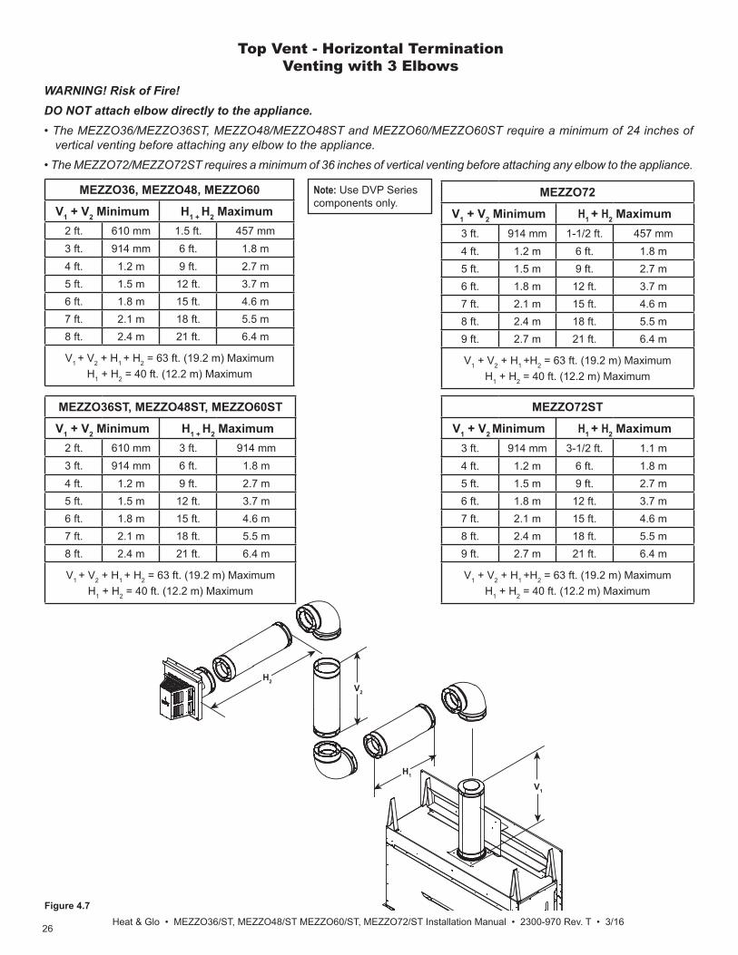
Figure 4.7
MEZZO36ST, MEZZO48ST, MEZZO60ST
V1 + V2 Minimum H1 + H2 Maximum2 ft. 610 mm 3 ft. 914 mm3 ft. 914 mm 6 ft. 1.8 m4 ft. 1.2 m 9 ft. 2.7 m5 ft. 1.5 m 12 ft. 3.7 m6 ft. 1.8 m 15 ft. 4.6 m7 ft. 2.1 m 18 ft. 5.5 m8 ft. 2.4 m 21 ft. 6.4 m
V1 + V2 + H1 + H2 = 63 ft. (19.2 m) MaximumH1 + H2 = 40 ft. (12.2 m) Maximum
H2
H1
V2
V1
MEZZO36, MEZZO48, MEZZO60
V1 + V2 Minimum H1 + H2 Maximum2 ft. 610 mm 1.5 ft. 457 mm3 ft. 914 mm 6 ft. 1.8 m4 ft. 1.2 m 9 ft. 2.7 m5 ft. 1.5 m 12 ft. 3.7 m6 ft. 1.8 m 15 ft. 4.6 m7 ft. 2.1 m 18 ft. 5.5 m8 ft. 2.4 m 21 ft. 6.4 m
V1 + V2 + H1 + H2 = 63 ft. (19.2 m) MaximumH1 + H2 = 40 ft. (12.2 m) Maximum
Note: Use DVP Series components only.
MEZZO72ST
V1 + V2 Minimum H1 + H2 Maximum3 ft. 914 mm 3-1/2 ft. 1.1 m4 ft. 1.2 m 6 ft. 1.8 m5 ft. 1.5 m 9 ft. 2.7 m6 ft. 1.8 m 12 ft. 3.7 m7 ft. 2.1 m 15 ft. 4.6 m8 ft. 2.4 m 18 ft. 5.5 m9 ft. 2.7 m 21 ft. 6.4 m
V1 + V2 + H1 +H2 = 63 ft. (19.2 m) MaximumH1 + H2 = 40 ft. (12.2 m) Maximum
MEZZO72
V1 + V2 Minimum H1 + H2 Maximum3 ft. 914 mm 1-1/2 ft. 457 mm4 ft. 1.2 m 6 ft. 1.8 m5 ft. 1.5 m 9 ft. 2.7 m6 ft. 1.8 m 12 ft. 3.7 m7 ft. 2.1 m 15 ft. 4.6 m8 ft. 2.4 m 18 ft. 5.5 m9 ft. 2.7 m 21 ft. 6.4 m
V1 + V2 + H1 +H2 = 63 ft. (19.2 m) MaximumH1 + H2 = 40 ft. (12.2 m) Maximum
WARNING! Risk of Fire! DO NOT attach elbow directly to the appliance. • The MEZZO36/MEZZO36ST, MEZZO48/MEZZO48ST and MEZZO60/MEZZO60ST require a minimum of 24 inches of
vertical venting before attaching any elbow to the appliance.• The MEZZO72/MEZZO72ST requires a minimum of 36 inches of vertical venting before attaching any elbow to the appliance.
Top Vent - Horizontal Termination Venting with 3 Elbows

27Heat & Glo • MEZZO36, MEZZO36ST, MEZZO48, MEZZO48ST Installation Manual • 2300-970 Rev. T • 3/16
Figure 4.8 Vertical Vent Maximum
Note: If installing a vertical vent/termination off the top of the appliance, the optional exhaust restrictor may be needed.
V
V = 3 ft Min. (1m), 50 ft. Max. (15.2 m)
Top Vent - Vertical TerminationNo Elbows
Note: Use DVP Series components only.

28Heat & Glo • MEZZO36/ST, MEZZO48/ST MEZZO60/ST, MEZZO72/ST Installation Manual • 2300-970 Rev. T • 3/16
Exhaust restrictors are recommended for these vertically terminated products which have excessive draft. Exhaust restrictors will compensate for high draft, and restore vi-sual fl ame height. If the vent confi guration has a total ver-tical of 20-50 feet, an exhaust restrictor may be needed. The exhaust restrictor can be located in the appliance manual bag.
Figure 4.9 Exhaust Restrictor
NOTICE: Before painting, contact your dealer for information on the appropriate high temperature paint.
Exhaust restrictor: MEZZO36, MEZZO48, MEZZO60 MEZZO721. Locate the two pilot holes in the inside fi rebox cham-
ber as shown in Figure 4.9.2. Break the fl ue restrictor into two pieces. Do this by
bending the part back and forth until it breaks. See Figure 4.10.
3. The setting for MEZZO36, MEZZO48, MEZZO60 and MEZZO72 is 2-2. Align the holes marked “2” on the numbered exhaust restrictor piece with the hole on the other exhaust restrictor piece. See Figure 4.11. Align the exhaust restrictor pieces with the pilot holes in the inner fi rebox chamber. Use two 1/2 inch self-piercing screws to secure vent restrictor to fi rebox heat shield.
4. In some applications, such as those where the fi re-place is elevated off the fl oor, the exhaust restrictor may be painted, but painting is not required.
EXHAUST RESTRICTOR
PILOT HOLES
Figure 4.10 Break the Exhaust Restrictor
1 2 3 4 5
SETTING
1 2 3 4 5
BREAKHERE
Exhaust restrictor Instructions
Figure 4.11 Set the Exhaust Restrictor
Exhaust restrictor: MEZZO36ST, MEZZO48ST MEZZO60ST, MEZZO72ST1. Break the fl ue restrictor into two pieces. Do this by
bending the part back and forth until it breaks. See Figure 4.10.
Note: The MEZZO36ST, MEZZO48ST, MEZZO60ST, and MEZZO72ST do not have pilot holes for the exhaust restrictor in the fi rebox chamber.2. The setting for MEZZO36ST, MEZZO48ST, MEZ-
ZO60ST, and MEZZO72ST is a 2.5 inch setting, or 2-2. Align the holes marked “2” on the numbered ex-haust restrictor piece with the hole on the other ex-haust restrictor piece. See Figure 4.11. Center the exhaust restrictor on the vent and secure in place with two 1/2 inch self-piercing screws.
3. In some applications, such as those where the fi re-place is elevated off the fl oor, the exhaust restrictor may be painted, but painting is not required.
NOTICE: Before painting, contact your dealer for information on the appropriate high temperature paint.

29Heat & Glo • MEZZO36, MEZZO36ST, MEZZO48, MEZZO48ST Installation Manual • 2300-970 Rev. T • 3/16
Figure 4.12
Top Vent - Vertical TerminationVenting with 2 elbows
MEZZO36, MEZZO48, MEZZO60 MEZZO36ST, MEZZO48ST, MEZZO60ST
V1 + V2 Minimum H Maximum2 ft. 610 mm 4 ft. 1.2 m3 ft. 914 mm 9 ft. 2.7 m4 ft. 1.2 m 12 ft. 3.6 m5 ft. 1.5 m 15 ft. 4.5 m
V1 + H1 + V2 = 63 ft. (19.2 m) MaximumHTotal = 23 ft. (7.1 m) Maximum
H1
V2
V1
MEZZO72, MEZZO72ST V1 + V2 Minimum H Maximum
3 ft. 914 mm 4 ft. 1.2 m4 ft. 1.2 m 9 ft. 2.7 m5 ft. 1.5 m 12 ft. 3.6 m6 ft. 1.8 m 15 ft. 4.5 m
V1 + H1 + V2 = 63 ft. (19.2 m) MaximumHTotal = 23 ft. (7.1 m) Maximum
WARNING! Risk of Fire! DO NOT attach elbow directly to the appliance. • The MEZZO36/MEZZO36ST, MEZZO48/MEZZO48ST and MEZZO60/MEZZO60ST require a minimum of 24 inches of
vertical venting before attaching any elbow to the appliance.• The MEZZO72/MEZZO72ST requires a minimum of 36 inches of vertical venting before attaching any elbow to the appliance.
Note: Use DVP Series components only.

30Heat & Glo • MEZZO36/ST, MEZZO48/ST MEZZO60/ST, MEZZO72/ST Installation Manual • 2300-970 Rev. T • 3/16
Figure 4.13
Top Vent - Vertical TerminationVenting with 3 elbows
Note: Use DVP Series components only.
MEZZO36, MEZZO36ST MEZZO48, MEZZO48STMEZZO60, MEZZO60ST
V1 + V2 Minimum H1 + H2 Maximum2 ft. 610 mm 4 ft. 1.2 m3 ft. 914 mm 9 ft. 2.7 m4 ft. 1.2 m 12 ft. 3.6 m5 ft. 1.5 m 15 ft. 4.5 m
V1 + V2 + H1 + H2 = 63 ft. (19.2 m) MaximumH1 + H2 = 23 ft. (7.1 m) Maximum
MEZZO72, MEZZO72ST
V1 + V2 Minimum H1 + H2 Maximum3 ft. 914 mm 4 ft. 1.2 m4 ft. 1.2 m 9 ft. 2.7 m5 ft. 1.5 m 12 ft. 3.6 m6 ft. 1.8 m 15 ft. 4.5 m
V1 + V2 + H1 + H2 = 63 ft. (19.2 m) MaximumH1 + H2 = 23 ft. (7.1 m) Maximum
INSTALLEDHORIZONTALLY
H1
H2
V1
V2
WARNING! Risk of Fire! DO NOT attach elbow directly to the appliance. • The MEZZO36/MEZZO36ST, MEZZO48/MEZZO48ST and MEZZO60/MEZZO60ST require a minimum of 24 inches of
vertical venting before attaching any elbow to the appliance.• The MEZZO72/MEZZO72ST requires a minimum of 36 inches of vertical venting before attaching any elbow to the appliance.

31Heat & Glo • MEZZO36, MEZZO36ST, MEZZO48, MEZZO48ST Installation Manual • 2300-970 Rev. T • 3/16
A. Pipe Clearances to CombustiblesWARNING! Risk of Fire! Maintain air space clearance to vent. DO NOT pack insulation or other combustibles:
• Between ceiling fi restops• Between wall shield fi restops• Around vent systemFailure to keep insulation or other material away from vent pipe could cause overheating and fi re.
5 5 Vent Clearances and Framing
B. Wall Penetration Framing/FirestopsCombustible Wall PenetrationWhenever a combustible wall is penetrated, you must frame a hole for the wall shield fi restop(s). The wall shield fi restop maintains minimum clearances and prevents cold air infi ltration.• The opening must be framed on all four sides using the
same size framing materials as those used in the wall construction.
• DVP pipe - A wall shield fi restop must be placed on each side of an interior wall. A minimum 1-1/2 in. (38 mm) overlap of attached heat shields must be main-tained.
• See Section 7.F. for information for regarding the instal-lation of a horizontal termination cap.
Non-Combustible Wall PenetrationIf the hole being penetrated is surrounded by non-com-bustible materials such as concrete, a hole with diameter one inch greater than the pipe is acceptable.Note: Do not pack the gap with insulation.Whenever a non-combustible wall is penetrated, the wall shield fi restop is only required on one side and no heat shield is necessary.
Figure 5.1 Horizontal Venting Clearances To Combustible Materials
Note: Heat shields MUST overlap by a minimum of 1-1/2 in. (38 mm). DVP heat shield - designed to be used on a wall 4 in. to 7-1/4 in. (102 mm to 184 mm) thick.
-HSM-B will be required.
(DVP Pipe Shown)
3 in. (76 mm)top clearance *
1 in. (25 mm)clearancebottom & sides
HeatShield
WallShield
Firestop
HeatShield
WALL
3 in. (76 mm)top clearance
1 in. (25 mm)clearance aroundvertical sections
Figure 5.2 Wall Penetration
* Shows center of vent framing hole for top venting. The center of the hole is one (1) in. (25.4 mm) above the center of the horizontal vent pipe.
MODEL A* BMEZZO36
MEZZ036ST MEZZO48
MEZZ048STMEZZO60
MEZZO60ST
64 in. 63 in.
1.63 m 1.6 m
MEZZO72MEZZO72ST
76 in. 75 in.
1.93 m 1.90 m
A
10 in.12 in.
B
DO NOT PACK WITH INSULATION OR OTHER MATERIAL
Note: Measurements were taken with a 2 ft. vertical section of pipe directly off the top of appliance.

32Heat & Glo • MEZZO36/ST, MEZZO48/ST MEZZO60/ST, MEZZO72/ST Installation Manual • 2300-970 Rev. T • 3/16
Figure 5.3 Installing Ceiling Firestop
Figure 5.4 Installing the Attic Shield
C. Install the Ceiling FirestopA ceiling fi restop MUST be used between fl oors and attics.• DVP pipe only - Frame an opening 10 in.
by 10 in. (254 mm by 254 mm) whenever the vent penetrates a ceiling/fl oor. See Figure 5.3.
• Frame the area with the same sized lumber as used in ceiling/fl oor joist.
• The ceiling fi restop may be installed above or below the ceiling joists when installed with an attic insulation shield. It must be under joists between fl oors that are not insulated. Refer to Figure 5.4.
• Secure with two fasteners on each side.WARNING! Risk of Fire! DO NOT pack insu-lation around the vent. Insulation must be kept back from the pipe to prevent overheating.
ATTIC ABOVE
A
PIPE
DVP
A
10 in. (254 mm)
A
INSTALL ATTIC INSULATION SHIELDSBEFORE OR AFTER INSTALLATION OF VENT SYSTEM
CEILING FIRESTOPINSTALLED BELOW CEILING
CEILING FIRESTOPINSTALLED ABOVE CEILING
D. Install Attic Insulation ShieldWARNING! Fire Risk. DO NOT allow loose materials or insulation to touch vent. Hearth & Home Technologies requires the use of an attic shield.The International Fuel Gas Code requires an attic shield constructed of 26 gauge minimum steel that extends at least 2 in. (51 mm) above insulation.• Attic insulation shields must meet specifi ed
clearances to combustible materials and be secured in place.
• An attic insulation shield kit is available from Hearth & Home Technologies. Contact your dealer to order. Install attic insulation shield according to instructions included with kit.

33Heat & Glo • MEZZO36, MEZZO36ST, MEZZO48, MEZZO48ST Installation Manual • 2300-970 Rev. T • 3/16
E. Installing the Optional Heat-Zone® Gas Kit
• Locate the Heat-Zone® ports on the left and right sides of the appliance. See Figure 5.5. Remove the knockouts from the appliance with a tin snips.
• Place the Heat-Zone® adapter box into position prior to the fi nal positioning of the fi replace as shown in Figure 5.5. Secure using eight self-tapping screws. Ensure the Heat-Zone® knockouts are completely covered by the adapter box.
• Center the duct collar around the exposed hole and attach it to the appliance with 3 screws.
Note: The adapter box will protrude out further than the one inch standoffs on the appliance. • Determine the location for the air register/fan housing
assembly. Reference the Heat-Zone® Kit instructions for theremaining installation steps.
Figure 5.5 Heat Zone Adapter
HEAT ZONE® LOCATIONLEFT AND RIGHT SIDES
HEAT ZONE® ADAPTER BOX

34Heat & Glo • MEZZO36/ST, MEZZO48/ST MEZZO60/ST, MEZZO72/ST Installation Manual • 2300-970 Rev. T • 3/16
CAUTION! Risk of Cuts, Abrasions or Flying Debris. Wear protective gloves and safety glasses during installation. Sheet metal edges are sharp.
A. Vent Collar Preparation
6 6 Appliance Preparation
FIBERGLASS ROPE RING
BOTTOM PANEL SCREW LOCATIONS
PIPE HEAT SHIELD
1. Position the pipe heat shield up against the header and attach to header with two screws.
WARNING! Risk of Fire! Pipe heat shield must be fas-tened to header.2. Place a 24 inch vent section on the starting collar.WARNING! Risk of Fire! DO NOT attach elbow directly to the appliance. • The MEZZO36/MEZZO36ST, MEZZO48/MEZZO48ST
and MEZZO60/MEZZO60ST require a minimum of 24 inches of vertical venting before attaching any elbow to the appliance.
• The MEZZO72/MEZZO72ST requires a minimum of 36 inches of vertical venting before attaching any elbow to the appliance.
3. Place the 1/8 inch thick, square fi berglass gasket over the initial 24 inch vent section.
4. Place the fi berglass rope ring over the gasket. Ensure both the gasket and the rope ring are seated on the top of the appliance. See Figure 6.2.
Figure 6.1 Location of Fiberglass Rope Ring
Figure 6.2 Fiberglass Rope Ring Installed
GASKETGASKET ROPE RINGROPE RING

35Heat & Glo • MEZZO36, MEZZO36ST, MEZZO48, MEZZO48ST Installation Manual • 2300-970 Rev. T • 3/16
B. Securing and Leveling the ApplianceWARNING! Risk of Fire! Prevent contact with:
• Sagging or loose insulation• Insulation backing or plastic• Framing and other combustible materialsBlock openings into the chase to prevent entry of blown-in insulation. Make sure insulation and other materials are secured.
DO NOT notch the framing around the appliance standoffs. Failure to maintain air space clearance could cause overheating and fi re.To properly position, level, and secure the appliance, see below. Nailing tabs are provided to secure the appliance to the framing members.• Bend out the two nailing tabs on each side.• Place the appliance into position.• Keep nailing tabs fl ush with the framing. See Figure 6.3. • Level the appliance from side to side and front to back.• Shim the appliance as necessary. It is acceptable to use
wood shims underneath the appliance.• Secure the appliance to the framing by using nails or
screws through the nailing tabs.Some fi gures in manual show the fi replace installed on the fl oor. However, this fi replace can be elevated off the fl oor provided that the fi replace is properly supported by framing materials and the ceiling clearances are maintained.
Figure 6.3 Nailing Tab Locations
NAILING TABSBOTH SIDES
Setting the Fireplace into the FramingThe left and right nailing tabs were designed as a means to ensure the fi replace is mounted fl ush with the framing materials. See Figures 6.3-6.5.1. The shipping fl anges protrude further out from the ap-
pliance than the side standoffs. The shipping fl ange may be bent upward or broken off in order to place the appliance into position in the framing.
2. Bend out all nailing tabs. The see-through model will have eight nailing tabs. The single-sided model will have four nailing tabs.
3. Screw each nailing tab to the adjoining framing ma-terial. Ensure that the one inch air space clearance is maintained on the sides and back of the fi replace. See Figures 3.5-3.8 for framing and clearance details.
Figure 6.4 Nailing TabsShipping Position
Figure 6.5 Nailing Tabs Installation Position
SHIPPING SHIPPING FLANGEFLANGE
NAILING NAILING TABTAB
SHIPPING SHIPPING FLANGEFLANGE
NAILING NAILING TABTAB
1 IN. STANDOFF1 IN. STANDOFF

36Heat & Glo • MEZZO36/ST, MEZZO48/ST MEZZO60/ST, MEZZO72/ST Installation Manual • 2300-970 Rev. T • 3/16
Figure 6.6 Install Factory-Included Non-Combustible Facing Material
C. Installing Non-Combustible Facing Material WARNING! Risk of Fire!• Follow these instructions exactly.• Facing materials must be installed properly to prevent fi re.
• No materials may be substituted without authorization by Hearth & Home Technologies.
• Remove protective cardboard sleeve from non-combustible facing pieces, which are included with the appliance.
• Install non-combustible facing material to the appliance using the 2 inch screws supplied in the manual bag assembly. There may be extra screws included.
• Attach top board to the framing members with regular sheetrock screws or nails. See Figure 6.6.
• Attach left and right side pieces to framing members with regular sheetrock screws or nails.
• Use a wet or dry towel or soft brush to remove dust or dirt from facing material.
• See Section 10 for fi nishing materials guidelines.

37Heat & Glo • MEZZO36, MEZZO36ST, MEZZO48, MEZZO48ST Installation Manual • 2300-970 Rev. T • 3/16
7 7 Venting and Chimneys
A. Assemble Vent Sections Attach Vent to the Firebox AssemblyNote: The end of the pipe sections with the lanced tabs will face toward the appliance.Attach the fi rst pipe section to the starting collar:• Lanced pipe end of the starting collar.• Inner pipe over inner collar.• Push the pipe section until all lanced tabs snap in place.• Lightly tug on pipe to confi rm it has locked.
Figure 7.1 High Temperature Silicone Sealant
Figure 7.2
A
B
Figure 7.3
Assemble Pipe SectionsPer Figure 7.2:• Start the inner pipe on the lanced end of section A into
the fl ared end of section B.• Start the outer pipe of section A over the outer pipe of
section B.• Once both vents sections are started, push fi rmly until
all lanced tabs lock into place.• Lightly tug on the pipe to confi rm the tabs have locked.It is acceptable to use screws no longer than 1/2 in. (13 mm) to hold outer pipe sections together. If predrilling holes, DO NOT penetrate inner pipe.For 90º and 45º elbows that are changing the vent direction from horizontal to vertical, one screw minimum should be put in the outer fl ue at the horizontal elbow joint to prevent the elbow from rotating. Use screws no longer than 1/2 in. (13 mm). If predrilling screw holes, DO NOT penetrate inner pipe.
Required Commercial, Multi-family (Multi-level exceeding two stories), or High-Rise ApplicationsAll outer pipe joints must be sealed with 100% silicone (300º F minimum continuous exposure rating), including the slip section that connects directly to the horizontal ter-mination cap. • Apply a bead of silicone sealant (300º F minimum con-
tinuous exposure rating) inside the female outer pipe joint prior to joining sections. See Figure 7.1.
• Only outer pipes need to be sealed. All unit collar, pipe, slip section, elbow and cap outer fl ues shall be sealed in this manner, unless otherwise stated.
WARNING! Risk of Fire or Explosion! DO NOT break silicone seals on slip sections. Use care when remov-ing termination cap from slip pipe. If slip section seals are broken during removal of the termination cap, vent could leak.
Figure 7.4 Seams
Note: Make sure that the seams are not aligned to prevent unintentional disconnection.
INCORRECT
CORRECT
LancesLances

38Heat & Glo • MEZZO36/ST, MEZZO48/ST MEZZO60/ST, MEZZO72/ST Installation Manual • 2300-970 Rev. T • 3/16
Figure 7.5 Slip Section Pilot Holes
Figure 7.6 Screws into Slip Section
Pilot holePilot hole
B. Assemble Slip Sections• Slide the inner fl ue of the slip section into the inner fl ue
of the pipe section and the outer fl ue of the slip section over the outer fl ue of the pipe section. See Figure 7.5.
• Slide together to the desired length.
• Continue adding pipe as necessary following instructions in “Assembling Pipe Sections.”
NOTICE: If slip section is too long, the inner and outer fl ues of the slip section can be cut to the desired length.NOTICE: When installing a vent system with an HRC termination cap, all pipe system joints shall be sealed using a silicone sealant with a minimum of 300ºF continuous exposure rating. • Apply a bead of silicone sealant inside the female outer
pipe joint prior to joining sections. • Only outer pipes are sealed, sealing the inner fl ue is not
required. • All unit collar, pipe, slip section, elbow and cap outer fl ues shall be sealed.
• Maintain a 1-1/2 in. (38 mm) overlap between the slip section and the pipe section.
• Secure the pipe and slip section with two screws no longer than 1/2 in. (13 mm), using the pilot holes in the slip section. See Figure 7.6.
120º
Figure 7.7 Securing Vertical Pipe Sections
120º
Figure 7.8 Securing Horizontal Pipe Sections
C. Secure The Vent Sections• Vertical runs originating off the top of the appliance, with
no offsets, must be supported every 8 ft. (2.44 m) after the maximum allowed 25 ft. (7.62 m) of unsupported rise.
• Vertical runs, after any elbow, must be supported every 5 ft. (1.52 m).
• Horizontal runs must be supported every 5 feet (1.52 m).• Vent supports or plumbers strap (spaced 120º apart)
may be used to support. See fi gures 7.7 and 7.8. • Wall shield fi restops may be used to provide horizontal
support.• Ceiling fi restops have tabs that may be used to provide
vertical support.WARNING! Risk of Fire, Explosion or Asphyxiation! Improper support could allow vent to sag and separate. Use vent run supports and connect vent sections per in-stallation instructions. DO NOT allow vent to sag below connection point to appliance.

39Heat & Glo • MEZZO36, MEZZO36ST, MEZZO48, MEZZO48ST Installation Manual • 2300-970 Rev. T • 3/16
D. Disassemble Vent Sections• Rotate either section (see Figure 7.9) so the seams on
both pipe sections are aligned as shown in Figure 7.10• Pull carefully to separate the pieces of pipe.
Figure 7.10 Align and Disassemble Vent Sections
Figure 7.9 Rotate Seams for Disassembly

40Heat & Glo • MEZZO36/ST, MEZZO48/ST MEZZO60/ST, MEZZO72/ST Installation Manual • 2300-970 Rev. T • 3/16
E. Vertical Termination RequirementsInstall Metal Roof Flashing• See minimum vent heights for various pitched roofs
(Figure 7.11) to determine the length of pipe to extend through the roof.
• Slide the roof fl ashing over the pipe sections extending through the roof as shown in Figure 7.12.
Roof Pitch H (Min.) Ft.Flat to 6/12........................................1.0*Over 6/12 to 7/12 ............................1.25*Over 7/12 to 8/12 ..............................1.5*Over 8/12 to 9/12 ..............................2.0*Over 9/12 to 10/12 ............................2.5*Over 10/12 to 11/12 ......................... 3.25Over 11/12 to 12/12 ........................... 4.0Over 12/12 to 14/12 ........................... 5.0Over 14/12 to 16/12 ........................... 6.0Over 16/12 to 18/12 ........................... 7.0Over 18/12 to 20/12 ........................... 7.5Over 20/12 to 21/12 ........................... 8.0
* 3 foot minimum in snow regions
Figure 7.11 Minimum Height From Roof To Lowest Discharge Opening
HORIZONTALOVERHANG
VERTICALWALL
GAS DIRECT VENT TERMINATION CAP
12X
ROOF PITCHIS X/ 12
LOWEST DISCHARGE
OPENING
2 FT.MIN.
20 INCHES MIN.
H (MIN.) - MINIMUM HEIGHT FROM ROOFTO LOWEST DISCHARGE OPENING
Figure 7.13 Install Bolt into BracketsFigure 7.13 Install Bolt into Brackets
NOTICE: Failure to properly caulk the roof fl ashing and pipe seams could permit entry of water.• Caulk the gap between the roof fl ashing and the outside
diameter of the pipe. • Caulk the perimeter of the fl ashing where it contacts the
roof surface. See Figure 7.12.• Caulk the overlap seam of any exposed pipe sections
that are located above the roof line.
CAULK
Figure 7.12 Figure 7.12
Assemble and Install Storm CollarCAUTION! Risk of Cuts, Abrasions or Flying Debris. Wear protective gloves and safety glasses during instal-lation. Sheet metal edges are sharp.• Slide the storm collar onto the exposed pipe section
and align brackets.• Insert a bolt (provided) through the brackets and install
nut. Do not completely tighten. See Figure 7.13.
• Slide the assembled storm collar down the pipe section until it rests on the roof fl ashing (see Figure 7.14).
• Tighten nut and make sure the collar is tight against the pipe section.
• Caulk around the top of the storm collar. See Figure 7.14.

41Heat & Glo • MEZZO36, MEZZO36ST, MEZZO48, MEZZO48ST Installation Manual • 2300-970 Rev. T • 3/16
Termination Cap
(1 of 3)
StormCollar
Caulk
Screws
Figure 7.14Figure 7.14
Install Vertical Termination Cap• Attach the vertical termination cap by sliding the inner
collar of the cap into the inner fl ue of the pipe section while placing the outer collar of the cap over the outer fl ue of the pipe section.
• Secure the cap by driving three self-tapping screws (supplied) through the pilot holes in the outer collar of the cap into the outer fl ue of the pipe. See Figure 7.14.
Important Notice: Heat shields may not be fi eld constructed.
F. Horizontal Termination Requirements Heat Shield Requirements for Horizontal TerminationWARNING! Risk of Fire! To prevent overheating and fi re, heat shields must extend through the entire wall thick-ness.
• DO NOT remove the heat shields attached to the wall shield fi restop and the horizontal termination cap (shown in Figure 7.15).
• Heat shields must overlap 1-1/2 in. (38 mm) mini-mum.
There are two sections of the heat shield. One section is factory-attached to the wall shield fi restop. The other section is factory-attached to the cap. See Figure 7.15.If the wall thickness does not allow the required 1-1/2 in. (38 mm) heat shield overlap when installed, an extended heat shield must be used.• If the wall thickness is less than 4 in./102 mm, the heat
shields on the cap and wall shield fi restop must be trimmed. A minimum 1-1/2 in. (38 mm) overlap MUST be maintained.
• Use an extended heat shield if the fi nished wall thickness is greater than 7-1/4 in. (184 mm).
• The extended heat shield may need to be cut to length maintaining suffi cient length for a 1-1/2 in. (38 mm) overlap between heat shields.
• Attach the extended heat shield to either of the existing heat shields using the screws supplied with the extended heat shield. Refer to vent components diagrams in the back of this manual.
• Rest the small leg on the extended heat shield on top of the pipe section to properly space it from the pipe section.

42Heat & Glo • MEZZO36/ST, MEZZO48/ST MEZZO60/ST, MEZZO72/ST Installation Manual • 2300-970 Rev. T • 3/16
Note: When using termination caps with factory-supplied heat shield attached, no additional wall shield fi restop is required on the exterior side of a combustible wall.
Install Horizontal Termination CapWARNING! Risk of Fire! The telescoping fl ue section of the termination cap MUST be used when connecting vent.
• 1-1/2 (38 mm) minimum overlap of fl ue telescoping section is required.
Failure to maintain overlap could cause overheating and fi re.
• Vent termination must not be recessed in the wall. Siding may be brought to the edge of the cap base.
• Flash and seal as appropriate for siding material at outside edges of cap.
• When installing a horizontal termination cap, follow the cap location guidelines as prescribed by current ANSI Z223.1 and CAN/CGA-B149 installation codes and refer to Section 6 of this manual.
CAUTION! Risk of Burns! Local codes may require in-stallation of a cap shield to prevent anything or anyone from touching the hot cap.NOTICE: For certain exposures which require superior resistance to wind-driven rain penetration, a fl ashing kit and HRC caps are available. When penetrating a brick wall, a brick extension kit is available for framing the brick.
Figure 7.15 Venting Through the Wall
INTERIOR
HEAT SHIELD OREXTENDED
HEAT SHIELDWALL SHIELD
FIRESTOP
HEAT SHIELD1-1/2 IN. (38 MM) MIN.
OVERLAP
SHEATHING
SLIP SECTIONCAN BE EXTENDED
INNER VENT
OUTER VENT
EXTERIOR

43Heat & Glo • MEZZO36, MEZZO36ST, MEZZO48, MEZZO48ST Installation Manual • 2300-970 Rev. T • 3/16
A. General InformationWARNING! Risk of Shock or Explosion! DO NOT wire 110-120 VAC to the valve or to the appliance wall switch. Incorrect wiring will damage controls.NOTICE: This appliance must be electrically wired and grounded in accordance with local codes or, in the absence of local codes, with National Electric Code ANSI/NFPA 70-latest edition or the Canadian Electric Code CSA C22.1.• Wire the appliance junction box to unswitched 110-
120 VAC. This is required for proper operation of the appliance.
• A 110-120 VAC circuit for this product must be protected with ground-fault circuit-interrupter protection, in compliance with the applicable electrical codes, when it is installed in locations such as in bathrooms or near sinks.
• Low voltage and 110/120 VAC voltage cannot be shared within the same wall box.
8 8 Electrical Information
Electrical Service and RepairWARNING! Risk of Shock! Label all wires prior to dis-connection when servicing controls. Wiring errors can cause improper and dangerous operation. Verify proper operation after servicing.WARNING! Risk of Shock! Replace damaged wire with type 105º C rated wire. Wire must have high temperature insulation.
Junction Box InstallationWARNING! Risk of Shock! Label all wires prior to dis-connection when servicing controls. Wiring errors can cause improper and dangerous operation. Verify proper operation after servicing.WARNING! Risk of Shock! Replace damaged wire with type 105° C rated wire. Wire must have high temperature insulation.
4. Route the wire through the strain relief in the outer wrap and up through the cutout/slot located on the metal tray under the junction box.
5. Make the connection inside the junction box to the 110-120V wire. Connect green to the ground nut, black to black, and white to white.
6. To reattach the junction box, insert one end of the junction box in the slot provided and securely screw the other end of the junction box to the control tray panel.
7. Reinstall component heat shield.
Figure 8.2 Junction Box Detail
Accessories Requirements• This appliance may be used with a wall switch, wall
mounted thermostat and/or a remote control.Wiring for optional Hearth & Home Technologies approved accessories should be done now to avoid reconstruction. Follow instructions that come with those accessories.
Figure 8.3. Valve Cavity (Lower Access Panel Removed)
In the event that the junction box may need to be ac-cessed or installed after fi nish methods have been ap-plied, access is possible by removing the vanity panel.
JUNCTION BOXJUNCTION BOXLED POWER LED POWER SUPPLYSUPPLY
AUXAUX
CONTROL MODULECONTROL MODULE
BATTERY BATTERY TRAYTRAY
COMPONENT COMPONENT HEAT SHIELDHEAT SHIELD
CAUTION! Risk of Overheating! Component heat shield MUST be installed before operating appliance. Electrical components will be damaged.
1. Remove bottom metal panel by removing two screws. Screw locations are shown in Figure 8.1. After removing two screws, gently lift the panel off the appliance avoiding contact with the non-combustible board if possible.
2. Remove the one screw that secures the junction box to the control tray panel. See Figure 8.2.
3. Remove screws on left and right sides of component heat shield and lift it out of the control cavity.
BOTTOM PANEL SCREW LOCATIONS
LOWER ACCESS PANEL
VANITY PANEL
Figure 8.1 Lower Access Panel Location
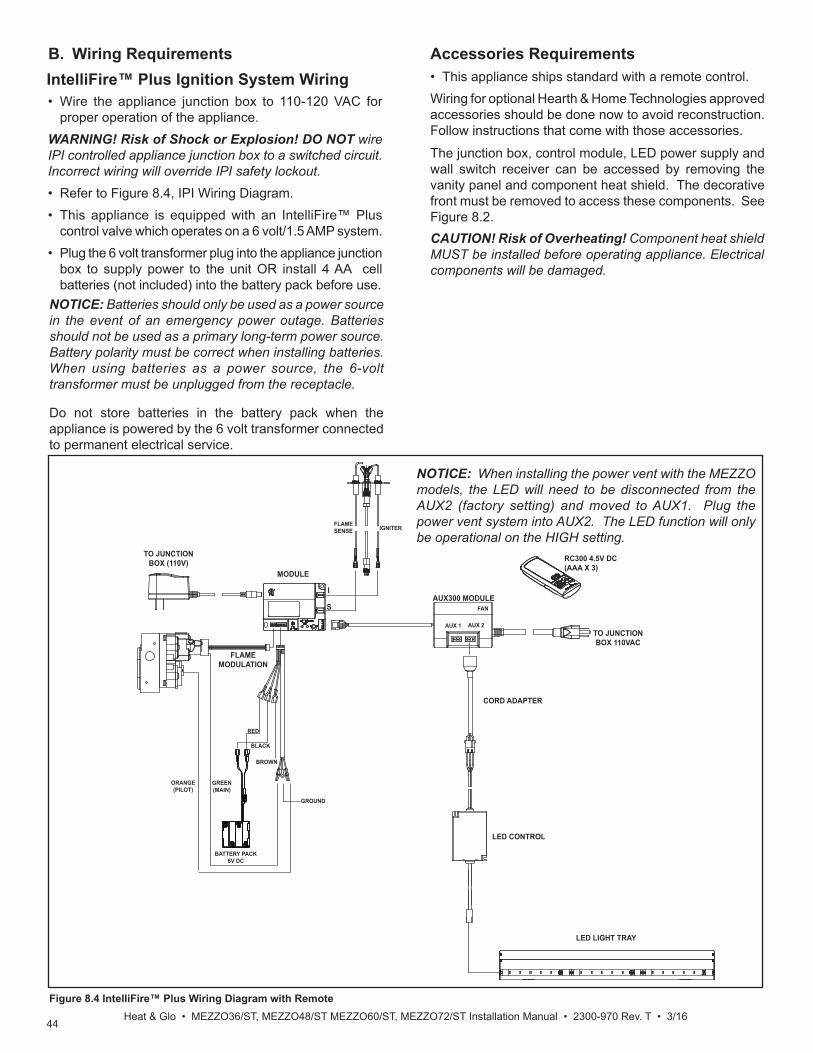
44Heat & Glo • MEZZO36/ST, MEZZO48/ST MEZZO60/ST, MEZZO72/ST Installation Manual • 2300-970 Rev. T • 3/16
Accessories Requirements• This appliance ships standard with a remote control.Wiring for optional Hearth & Home Technologies approved accessories should be done now to avoid reconstruction. Follow instructions that come with those accessories.
The junction box, control module, LED power supply and wall switch receiver can be accessed by removing the vanity panel and component heat shield. The decorative front must be removed to access these components. See Figure 8.2.
IntelliFire™ Plus Ignition System Wiring• Wire the appliance junction box to 110-120 VAC for
proper operation of the appliance.WARNING! Risk of Shock or Explosion! DO NOT wire IPI controlled appliance junction box to a switched circuit. Incorrect wiring will override IPI safety lockout.• Refer to Figure 8.4, IPI Wiring Diagram.• This appliance is equipped with an IntelliFire™ Plus
control valve which operates on a 6 volt/1.5 AMP system.• Plug the 6 volt transformer plug into the appliance junction
box to supply power to the unit OR install 4 AA cell batteries (not included) into the battery pack before use.
B. Wiring Requirements
NOTICE: Batteries should only be used as a power source in the event of an emergency power outage. Batteries should not be used as a primary long-term power source. Battery polarity must be correct when installing batteries. When using batteries as a power source, the 6-volt transformer must be unplugged from the receptacle.
Do not store batteries in the battery pack when the appliance is powered by the 6 volt transformer connected to permanent electrical service.
Figure 8.4 IntelliFire™ Plus Wiring Diagram with Remote
LED LIGHT TRAY
TO JUNCTION BOX (110V)
MODULE
I
S
FLAME SENSE IGNITER
RC300 4.5V DC (AAA X 3)
TO JUNCTION BOX 110VAC
ORANGE(PILOT)
GREEN(MAIN)
FLAME MODULATION
AUX300 MODULE
AUX 1 AUX 2
FAN
GROUND
BROWN
BLACK
RED
BATTERY PACK6V DC
LED CONTROL
CORD ADAPTER
CAUTION! Risk of Overheating! Component heat shield MUST be installed before operating appliance. Electrical components will be damaged.
NOTICE: When installing the power vent with the MEZZO models, the LED will need to be disconnected from the AUX2 (factory setting) and moved to AUX1. Plug the power vent system into AUX2. The LED function will only be operational on the HIGH setting.

45Heat & Glo • MEZZO36, MEZZO36ST, MEZZO48, MEZZO48ST Installation Manual • 2300-970 Rev. T • 3/16
A. Fuel Conversion• Make sure the appliance is compatible with available gas
types.• Conversions must be made by a qualified service
technician using Hearth & Home Technologies specifi ed and approved parts.
B. Gas Pressure• Optimum appliance performance requires proper input
pressures.• Gas line sizing requirements will be determined in ANSI
Z223.1 National Fuel Gas Code in the USA and CAN/CGA B149 in Canada.
• Pressure requirements are:
9 9 Gas Information
Gas Pressure Natural Gas PropaneMinimum inlet pressure 5.0 in. w.c. 11.0 in. w.c.Maximum inlet pressure 10.0 in. w.c. 13.0 in. w.c.Manifold pressure 3.5 in. w.c. 10.0 in. w.c.
Note: Have the gas supply line installed in accordance with local codes, if any. If not, follow ANSI 223.1. Installation should be done by a qualifi ed installer approved and/or licensed as required by the locality. (In the Commonwealth of Massachusetts installation must be performed by a licensed plumber or gas fi tter).
Note: A listed (and Commonwealth of Massachusetts ap-proved) 1/2 in. (13 mm) T-handle manual shut-off valve and fl exible gas connector are connected to the 1/2 in. (13 mm) control valve inlet. • If substituting for these components, please consult
local codes for compliance.
Fire Risk.Explosion Hazard.High pressure will damage valve.• Disconnect gas supply piping BEFORE
pressure testing gas line at test pressures above 1/2 psig.
• Close the manual shutoff valve BEFORE pressure testing gas line at test pressures equal to or less than 1/2 psig.
WARNING
WARNING! Risk of Fire or Explosion! High pressure will damage valve. Low pressure could cause explosion.• Verify inlet pressures. Verify minimum pressures when
other household gas appliances are operating. • Install regulator upstream of valve if line pressure is
greater than 1/2 psig.• Valve pressure taps are accessible by removing the
decorative front and the vanity panel.
Figure 9.1. Valve Pressure Taps.
Note: This appliance does include a manual gas shutoff valve that is located in the valve compartment. This manual gas shutoff valve is accessible for service by removing the decorative front and the vanity panel. The valve is most accessible if it is located forward in the control cavity of the appliance.Depending upon local code, an additional manual gas shutoff, in a readily accessible area may be required and located upstream from the appliance. The lower access cover panel is removable if fi nishing material is not installed. See Figure 9.2.
VALVE PRESSURE TAPSVALVE PRESSURE TAPS
C. Gas Service Access
If the fi nishing materials have been installed around the appliance opening, proceed as follows:1. Remove vanity panel.2. Remove screws on left and right sides of component
heat shield and lift it out of the control cavity.
BOTTOM PANEL SCREW LOCATIONS
LOWER ACCESS PANEL
VANITY PANEL
Figure 9.2. Vanity Panel and Lower Access Panel Location
3. Unplug the 6V transformer from the junction box. This will turn the power off to the appliance.
CAUTION! Risk of Overheating! Component heat shield MUST be installed before operating appliance. Electrical components will be damaged.

46Heat & Glo • MEZZO36/ST, MEZZO48/ST MEZZO60/ST, MEZZO72/ST Installation Manual • 2300-970 Rev. T • 3/16
Figure 9.5. Gas Fitting Access with Vanity Panel Removed
Figure 9.4. Gas and Electrical Access - Remove Glass Window
PILOT SHIELD
BURNER ASSEMBLY4836 & 6048
MEDIA TRAY
BURNER ASSEMBLY7260 & 8472
GAS VALVE
GAS ACCESS
Figure 9.3. Media Tray with Burner and Pilot Shield
4. Turn the gas shutoff handle to the “OFF” position to shut off the gas supply.
If additional access is needed, proceed as follows:5. Remove glass assembly from appliance by unlatch-
ing the top spring latches from the glass frame and lifting glass frame assembly out of the bottom brack-et.
6. Remove interior media and refractory from the unit if already installed.
7. Remove the media tray. It is attached to the interior fi rebox bottom with ten screws. See Figure 9.3.
8. Remove the two screws that attach the pilot to the burner.
9. Remove the four screws securing the burner to the fi rebox sides and disengage burner from orifi ce. Re-move burner. See Figure 9.3.
10. Remove the eight screws that secure the glass window. Remove the glass window. Handle with care. See Figure 9.4.
11. Remove light tray from appliance by lifting up and out through the bottom glass opening.

47Heat & Glo • MEZZO36, MEZZO36ST, MEZZO48, MEZZO48ST Installation Manual • 2300-970 Rev. T • 3/16
D. Gas Connection • Refer to Reference Section 3.A for location of gas line
access in appliance.• Gas line may be run through the left side of appliance.• The gap between supply piping and gas access hole
may be caulked with caulk with a minimum of 300ºF continuous exposure rating or stuffed with non-combustible, unfaced insulation to prevent cold air infi ltration.
• Ensure that gas line does not come in contact with outer wrap of the appliance. Follow local codes.
• Pipe incoming gas line into valve compartment.• Connect incoming gas line to the 1/2 in. (13 mm)
connection on manual shutoff valve.WARNING! Risk of Fire or Explosion! Support control when attaching pipe to prevent bending gas line.• A small amount of air will be in the gas supply lines. WARNING! Risk of Fire or Explosion! Gas build-up dur-ing line purge could ignite.
• Purge should be performed by qualified service technician.
• Ensure adequate ventilation. • Ensure there are no ignition sources such as sparks
or open fl ames.Light the appliance. It will take a short time for air to purge from lines. When purging is complete the appliance will light and operate normally.WARNING! Risk of Fire, Explosion or Asphyxiation! Check all fi ttings and connections with a non-corrosive commercially available leak-check solution. DO NOT use open fl ame. Fittings and connections could have loos-ened during shipping and handling.WARNING! Risk of Fire! DO NOT change valve settings. This valve has been preset at the factory.
E. High Altitude InstallationsNOTICE: If the heating value of the gas has been reduced, these rules do not apply. Check with your local gas utility or authorities having jurisdiction.When installing above 2000 feet elevation:• In the USA: Reduce burner orifi ce 4% for each 1000 feet
above 2000 feet.• In CANADA: Reduce burner orifi ce 10% for elevations
between 2000 feet and 4500 feet. Above 4500 feet, consult local gas utility.

48Heat & Glo • MEZZO36/ST, MEZZO48/ST MEZZO60/ST, MEZZO72/ST Installation Manual • 2300-970 Rev. T • 3/16
Figure 9.6 Air Shutter Location
F. Air Shutter SettingAir shutter settings may be adjusted by a qualifi ed install-er at the time of installation. The air shutter is set at the factory for minimum vertical vent run. Adjust air shutter for longer vertical runs. See Figure 9.6.• Refer to Gas Service Access instructions in Section 9.C
to access the air shutter.• Loosen the 1/4 in. screw.
Air Shutter SettingsMEZZO36
MEZZO36STMEZZO48
MEZZO48ST
NG Propane
GLASS REFRACTORY KIT
Standard Opening=
3/16 in.
Standard Opening=Full Open
LOG KIT 1/4 in. Full Open
DETAIL
• Twist shutter to adjust.• Shutter may be open for longer horizontal vent runs.• Do not close the air shutter more than 1/16 in. for NG or
1/4 in. for propane.• Tighten the screw.NOTICE: If sooting occurs, provide more air by opening the air shutter.
MEZZO60MEZZO60ST NG Propane
GLASS REFRACTORY KIT
Standard Opening=
3/8 in.
Standard Opening=Full Open
LOG KIT 3/8 in. Full Open
MEZZO72MEZZO72ST NG Propane
GLASS REFRACTORY KIT
Standard Opening=
1/2 in.
Standard Opening=Full Open
LOG KIT 1/2 in. Full Open

49Heat & Glo • MEZZO36, MEZZO36ST, MEZZO48, MEZZO48ST Installation Manual • 2300-970 Rev. T • 3/16
10 10 Finishing A. Facing and Finishing InstructionsWARNING! Risk of Fire! Comply with all minimum clear-ances to combustibles as specifi ed. Framing closer than the minimums listed must be constructed entirely of noncom-bustible materials (i.e., steel studs, concrete board, etc.).
Splatter GuardThe splatter guard is a piece of corrugated material used to protect the appliance during the installation process before fi nishing work on the whole hearth is complete. A splatter guard is factory-installed on MEZ-ZO models. Splatter guards must be removed before appliance is fi red.WARNING! Risk of Fire! Remove the splatter guard be-fore lighting the appliance. Shut off gas to the appliance when the splatter guard is in place to prevent accidental operation.Finishing Instructions It is important to follow the framing and fi nishing instruc-tions to ensure proper placement of fi replace into the sur-rounding framing/fi nishing materials.Wall sheathing materials 1/2 in. thick are specifi ed in this installation manual to properly align with the installed non-combustible material.WARNING! Risk of Fire! DO NOT remove the installed non-combustible board or cover it with combustible mate-rial, such as:
• Drywall (gypsum board)• Plywood• Materials that do not meet the ASTM E 136 Non-com-
bustibility standard (below).Removal of installed, non-combustible board and/or use of materials not meeting the ASTM E 136 standard could cause fi re.
Non-Combustible Materials Specifi cationMaterial which will not ignite and burn. Such materials are those consisting entirely of steel, iron, brick, tile, concrete, slate, glass or plasters, or any combination thereof.Materials that are reported as passing ASTM E 136, Standard Test Method for Behavior of Materials in a Vertical Tube Furnace at 750 ºC.
WARNING! Risk of Fire! DO NOT use screws longer than two inches when attaching fi nishing materials to in-stalled non-combustible material. Screws longer than two inches will compromise clearance and could cause over-heating and fi re.
WARNING! Risk of Fire! Maintain specifi ed air space clearances to combustibles. Inadequate air space could cause overheating and fi re.
NOTICE: The maximum fi nishing material not only includes the decorative fi nish materials (marble, tile, slate, etc) but also the thin set, lath and adhesive used to attach the decorative fi nish material.
Finishing Materials
WARNING! Risk of Fire, Explosion or Asphyxiation! DO NOT use screws more than one inch long on lower cover panel. Longer screws may penetrate gas line or damage valve or electrical components.This section discusses installation details associated with the Inside and Overlap Fit methods and specifi es additional non-combustible materials required.When fi nishing the wall around the fi replace, it is critical that wall sheathing be fastened properly. Wall sheathing fasteners, such as screws or nails, are not permitted in some locations. See Figure 10.1. It is acceptable to pre-drill holes and use self-tapped screws in the installed non-combustible board which may be used to lathe (a backer for tile, marble, etc.). Screws being installed through the installed non-combustible board should be self-tapping type with a maximum length of 2 inches. See Figure 10.1. When installing fi nish material on the lower cover panel, DO NOT drill or install screws longer than one inch.Screws longer than one inch could penetrate the lower cover panel causing damage to components or penetrate the gas line. One inch screws are included in the manual bag assembly that are intended for use when attaching fi nishing material to lower cover panel. See Figure 10.1. In regards to the sheetrock mud, a smooth, even surface, covering a wide area of the wall is desired for best results. For best results, follow the tips below.
To Reduce the Risk of Sheetrock Cracking: DO
Use all purpose joint compound.Use eggshell paint (gloss or semi-gloss).
To Avoid Sheetrock Cracking:DO NOT
Use a quick set or light weight joint compound.Use fl at paint.

50Heat & Glo • MEZZO36/ST, MEZZO48/ST MEZZO60/ST, MEZZO72/ST Installation Manual • 2300-970 Rev. T • 3/16
WARNING! Risk of Fire, Explosion or Asphyxiation! DO NOT use screws more than one inch long on lower cover panel. Longer screws may penetrate gas line or damage valve or electrical components.
Figure 10.1 Screw Length Requirements
Note: It is acceptable to use a high temperature silicone sealant to adhere drywall to lower cover panel.
Finish and Sealing JointsAll joints between the fi nished wall sheathing and the ap-pliance must be sealed with non-combustible materials. Sealants, such as caulk or mastic used to seal the gap between the wall and the fi replace, should be rated at a minimum continuous exposure to 300ºF. Finishing Around Opening with Gypsum WallboardGypsum wallboard (drywall) joints adjacent to the fi re-place opening, including the non-combustible board on the appliance, require special attention to minimize crack-ing. When installing gypsum wallboard around the fi re-place, install the hole for the fi replace opening in a single wallboard sheet, if possible. This will minimize the joints adjacent to the fi replace opening. Tape wall board joints around the fi replace opening with fi berglass-mesh tape. It will provide a more crack-resis-tant joint than paper tape. Fill, smooth and fi nish wall joints with chemically setting-type joint compound. It will provide a more crack-resistant joint than air-drying light-weight compound.PaintingIf desired fi nishing includes a painted wall, 100% acrylic latex with compatible primer is recommended around this appliance. Oil-based or standard acrylic paints may dis-color due to heat exposure.
Facing Material• Facing and/or fi nishing materials must not interfere with
air fl ow through louvers or decorative fronts. • Facing and/or fi nishing materials must never overhang
into the glass opening.• Observe all clearances when applying combustible
materials.
Figure 10.2 Finishing and Facing Materials - Single-Sided Models
The appliance is designed to mate with 1/2 in. wall sheathing materials such as drywall, plywood, wood composites, or non-combustible materials.
WARNING! Risk of Fire! DO NOT apply combustible materials beyond the minimum clearances. Comply with all minimum clearances to combustibles as specifi ed in this manual. Overlapping materials could ignite and will interfere with proper operation of doors and louvers.WARNING! Risk of Fire! DO NOT install drywall or other combustible materials directly onto the installed non-combustible board. Overlapping materials could ignite.
MAXIMUM SCREW LENGTH = 1 INCH(LOWER COVER PANEL)
MAXIMUM SCREW LENGTH = 2 INCHES(INSTALLED NON-COMBUSTIBLE BOARD)
NON-COMBUSTIBLE MATERIAL ONLY IN THIS AREA
= NO FASTENERS IN THIS AREA
2 IN.
1/2 IN. THICK WALL SHEATHING
BOTTOMFINISHING TEMPLATE
Finishing - Hearth See Inside Fit or Overlap Method sections to determine the necessary requirements for installation of a non-combustible hearth for this model. Only hearths made of non-combustible materials are allowed.
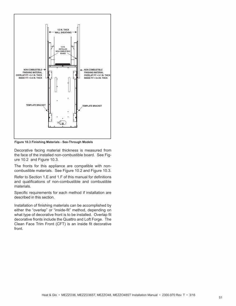
51Heat & Glo • MEZZO36, MEZZO36ST, MEZZO48, MEZZO48ST Installation Manual • 2300-970 Rev. T • 3/16
Figure 10.3 Finishing Materials - See-Through Models
Decorative facing material thickness is measured from the face of the installed non-combustible board. See Fig-ure 10.2 and Figure 10.3.The fronts for this appliance are compatible with non-combustible materials. See Figure 10.2 and Figure 10.3.Refer to Section 1.E and 1.F of this manual for defi nitions and qualifi cations of non-combustible and combustible materials.Specifi c requirements for each method if installation are described in this section.
Installation of fi nishing materials can be accomplished by either the “overlap” or “inside-fi t” method, depending on what type of decorative front is to be installed. Overlap fi t decorative fronts include the Quattro and Loft Forge. The Clean Face Trim Front (CFT) is an inside fi t decorative front.
TEMPLATE BRACKET
1/2 IN. THICK WALL SHEATHING
TEMPLATE BRACKET
1/2 IN. INSTALLED
NON-COMBUSTIBLE BOARD
NON-COMBUSTIBLE FINISHING MATERIAL
OVERLAP FIT = 0-1 IN. THICK INSIDE FIT = 0-4 IN. THICK
NON-COMBUSTIBLE FINISHING MATERIALOVERLAP FIT = 0-1 IN. THICK INSIDE FIT = 0-4 IN. THICK

52Heat & Glo • MEZZO36/ST, MEZZO48/ST MEZZO60/ST, MEZZO72/ST Installation Manual • 2300-970 Rev. T • 3/16
NOTICE: This one inch maximum not only includes the decorative fi nish materials (marble, tile, slate, etc) but also the thin set, lath and adhesive used to attach the decorative fi nish material.1. The non-combustible fi nish material can be installed
up to the fi replace opening on the top and sides. Do not cover rectangular access holes. See Figure 10.4 and 10.5.
0 - 1 inch thickness-Overlap Fit MethodAll overlap fronts are designed to accept fi nish materials 0 inches to 1 inch thick. See Figure 10.3. If installing an overlap front (Quattro, Loft Forge), the fi nishing mate-rial will be placed up to the bottom edge of the fi nishing template.
Non-Combustible Finish Materials
= RECTANGULAR ACCESS HOLES DO NOT COVER
BOTTOM ACCESS PANEL
FINISHING TEMPLATE
Figure 10.4 Non-Combustible Finish Material Diagram for 0-1 Inch Thick Overlap Fit Method
WARNING! Risk of Fire! DO NOT apply combustible materials beyond the minimum clearances. Comply with all minimum clearances to combustibles as specifi ed in this manual. Overlapping materials could ignite.
WARNING! Risk of Fire! DO NOT cover rectangular holes on bottom access panel when installing overlap fronts.• If a Clean Face Trim (CFT) front has been installed and is to be replaced by a front with an overlap fi t, the fi nishing material must be removed to reveal the eight rectangular holes on the bottom access panel.• Overheating and fi re could occur.
2. Remove fi nishing template from bottom access panel. 3. Follow instructions provided with decorative front for installation.
Figure 10.5 Finishing and Facing Materials - Overlap Fit
BOTTOMFINISHING TEMPLATE
MAXIMUM HEARTH OR FLOOR HEIGHT ABOVE BOTTOM OF APPLIANCE = 0 INCHES
Finishing - Non-Combustible Hearth - Overlap Fit • A non-combustible hearth may be installed at the same
level as the bottom of the appliance or lower. It may not cover any part of the appliance. See Figure 10.6.
WARNING! Risk of Fire! DO NOT allow any part of ap-pliance to be covered by hearth or fl oor.
Overlap Fit Finishing

53Heat & Glo • MEZZO36, MEZZO36ST, MEZZO48, MEZZO48ST Installation Manual • 2300-970 Rev. T • 3/16
FIREPLACE VIEWING AREA17-1/4 IN.
51-1/8 IN.MEZZO48/MEZZO48ST39-1/8 IN.MEZZO36/MEZZO36ST
63-1/8 IN.MEZZO60/MEZZO60ST
Figure 10.6 Finished Opening Dimensions - Overlap Fit Method

54Heat & Glo • MEZZO36/ST, MEZZO48/ST MEZZO60/ST, MEZZO72/ST Installation Manual • 2300-970 Rev. T • 3/16
TRIM RING INSTALLED
Non-Combustible Finish MaterialsClean Face Trim (CFT) Front Only0 Inches to 1 Inch Thick Inside Fit Method
WARNING! Risk of Fire! • If a Clean Face Trim (CFT) front has been installed and is to be replaced by a front with an overlap fi t, the fi nishing material must be removed to reveal the eight rectangular holes on the bottom access panel.• Over heating and fi re could occur.
NOTICE: This one inch maximum not only includes the decorative fi nish materials (marble, tile, slate, etc) but also the thin set, lath and adhesive used to attach the decorative fi nish material.
The Clean Face Trim decorative front is approved for in-side fi t applications. When using non-combustible fi nish-ing materials 0-1 inch thick, follow the instructions below. Refer to Section 1.E and 1.F of this manual for defi nition and qualifi cations and defi nition of non-combustible and combustible materials.1. Remove fi nishing template from bottom access panel. 2. Install fi nishing material to the top ledge of the bot-
tom access panel, covering the eight rectangle holes in the access panel. See Figure 10.1 for screw length requirements.
3. Install trim ring onto the wall. The trim ring acts as a fi nishing template in this application. Finishing materi-als may not extend past the outside edge of the trim ring.
4. Follow instructions provided with decorative front for installation.
Note: When a Clean Face Trim decorative front is installed, the rectangular holes in bottom access panel will be covered.
Non-Combustible Finish MaterialsClean Face Trim (CFT) Front Only1 Inch to 4 Inches Thick Inside Fit Method
WARNING! Risk of Fire! DO NOT apply combustible materials beyond the minimum clearances. Comply with all minimum clearances to combustibles as specifi ed in this manual. Overlapping materials could ignite.
Finishing material greater than one inch thick is only ap-proved for non-combustible materials with a Clean Face Trim front only. Refer to Section 1.E and 1.F of this man-ual for defi nition and qualifi cations and defi nition of non-combustible and combustible materials.
1. Remove fi nishing template from bottom access panel. 2. Install trim ring onto the wall. The trim ring acts as a fi nishing template in this application. Finishing materi-als may not extend past the outside edge of the trim ring.
NOTICE: If fi nishing extends past the inside opening of the outer trim ring, the decorative front will not fi t.
4. Follow instructions provided with decorative front for installation.
WARNING! Risk of Fire! • If a Clean Face Trim (CFT) front has been installed and is to be replaced by a front with an overlap fi t, the fi nishing material must be removed to reveal the eight rectangular holes on the bottom access panel.• Over heating and fi re could occur.
3. Install non-combustible fi nishing material up to the out-er edges of the trim ring. See Figure 10.1 for screw length requirements.
Figure 10.7 Non-Combustible Finish Material Diagram for 1-4 Inch Thick Inside Fit Method
Inside Fit Finishing
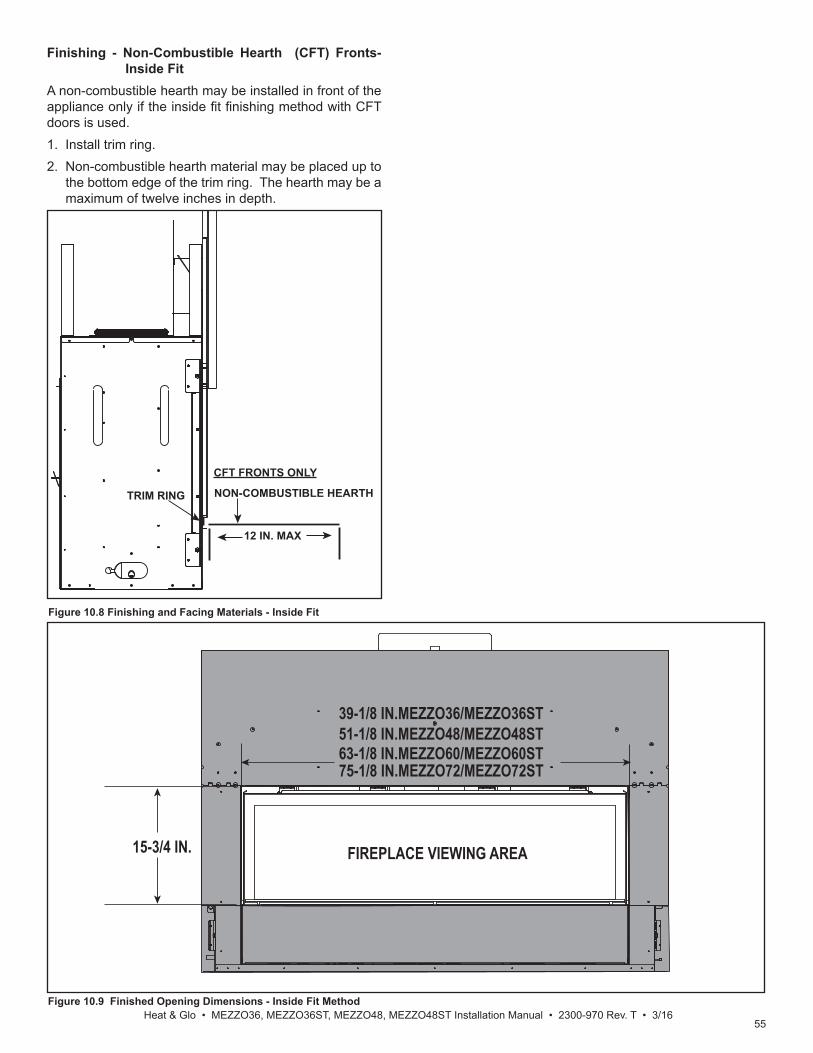
55Heat & Glo • MEZZO36, MEZZO36ST, MEZZO48, MEZZO48ST Installation Manual • 2300-970 Rev. T • 3/16
FIREPLACE VIEWING AREA15-3/4 IN.
51-1/8 IN.MEZZO48/MEZZO48ST39-1/8 IN.MEZZO36/MEZZO36ST
63-1/8 IN.MEZZO60/MEZZO60ST75-1/8 IN.MEZZO72/MEZZO72ST
Figure 10.8 Finishing and Facing Materials - Inside Fit
TRIM RING
CFT FRONTS ONLY
12 IN. MAX
NON-COMBUSTIBLE HEARTH
Finishing - Non-Combustible Hearth (CFT) Fronts-Inside Fit
A non-combustible hearth may be installed in front of the appliance only if the inside fi t fi nishing method with CFT doors is used. 1. Install trim ring.2. Non-combustible hearth material may be placed up to
the bottom edge of the trim ring. The hearth may be a maximum of twelve inches in depth.
Figure 10.9 Finished Opening Dimensions - Inside Fit Method

56Heat & Glo • MEZZO36/ST, MEZZO48/ST MEZZO60/ST, MEZZO72/ST Installation Manual • 2300-970 Rev. T • 3/16
B. Mantel and Wall ProjectionsWARNING! Risk of Fire! Comply with all minimum clear-ances to combustibles as specifi ed. Framing closer than the minimums listed must be constructed entirely of noncom-bustible materials (i.e., steel studs, concrete board, etc.)
Combustible Mantels
Note: For non-combustible fi replace fi nish material (marble, stone, etc) specifi cations refer to Section 10.A.
Figure 10.10 Minimum Vertical and Maximum Horizontal Dimensions of Combustibles - MEZZO36 and
MEZZO48
MEASUREMENT FROMTOP EDGE OPENING
1820
2326
29
31
TO CEILING
912
63
1
Measurement from top edge opening to bottom of appliance = 24-1/2 IN.
MAX.
Note: All measurements in inches.
MEASUREMENT FROMTOP EDGE OPENING
24
27
30
31
TO CEILING
96
3
Measurement from top edge opening to bottom of appliance = 24-1/2 IN.
MAX.
Figure 10.11 Minimum Vertical and Maximum Horizontal Dimensions of Combustibles - MEZZO60 and
MEZZO72
Note: All measurements in inches.

57Heat & Glo • MEZZO36, MEZZO36ST, MEZZO48, MEZZO48ST Installation Manual • 2300-970 Rev. T • 3/16
Non-Combustible Mantels
Note: All measurements in inches.
Figure 10.12 Minimum Vertical and Maximum Horizontal Dimensions of Non-Combustibles - Overlap Fit
Finishing
MEASUREMENTS FROM TOP EDGE OF THE APPLIANCE OPENING
4
5
6
13-16
3
2
1
67
89
1011
18
31
MAX.
MIN.
TO CEILING
Measurement from top edge of openingto bottom of appliance = 24-1/2 IN.
3 FT. MAXIMUM4-1/2 IN. MINIMUM
FIREPLACE OPENINGSee Appliance Dimension Diagram-Dimension BFigure 3.1 (MEZZO36, MEZZO48)Figure 3.2 (MEZZO60, MEZZO72)Figure 3.3 (MEZZO36ST, MEZZO48ST)Figure 3.4 (MEZZO60ST, MEZZO72ST)
Figure 10.14 Mantel Leg or Wall Projections (Acceptable on both sides of opening)
7 IN. MINIMUM UNLIMITED
FIREPLACE OPENINGSee Appliance Dimension Diagram-Dimension BFigure 3.1 (MEZZO36, MEZZO48)Figure 3.2 (MEZZO60, MEZZO72)Figure 3.3 (MEZZO36ST, MEZZO48ST)Figure 3.4 (MEZZO60ST, MEZZO72ST)
Note: Clearance from opening to perpendicular wall.
Note: Clearance from opening to perpendicular wall.
Mantel Legs Or Wall Projections Extending Past The Face Of The Fireplace (Combustible or Non-Combustible)
Figure 10.15 Mantel Leg or Wall Projections (Acceptable on both sides of opening)
Figure 10.13 Minimum Vertical and Maximum Horizontal Dimensions of Non-Combustibles - Inside Fit Finishing
MEASUREMENTS FROM TOP EDGE OF THE APPLIANCE OPENING
4
5
6
14-16
0-910
18
31 MIN.
MAX.
TO CEILING
Measurement from top edge of openingto bottom of appliance = 24-1/2 IN.
7
11
OVERLAP FIT
INSIDE FITNote: All measurements in inches.

58Heat & Glo • MEZZO36/ST, MEZZO48/ST MEZZO60/ST, MEZZO72/ST Installation Manual • 2300-970 Rev. T • 3/16
C. Decorative Front Dimensions for Finishing
Only decorative fronts certifi ed for use with this appliance model may be used. Contact your dealer for a list of dec-orative fronts that may be used. The doors approved for use with this appliance have been designed to be installed by two methods: Overlap Fit or Inside Fit. Before beginning the installation, it is im-portant to determine with method will be used.Overlap Fit Doors (Loft Forge/Quattro): These doors have been designed to be installed over fi nishing mate-rial up to one inch thick. Finishing materials may be a maximum of 1 in. thick. Stop fi nishing material fl ush with opening on top and sides. Stop fi nishing material fl ush with fi nishing template on bottom. Inside Fit Doors (Clean Face Trim front): These doors are installed fl ush with the non-combustible fi nishing ma-terial up to four inches thick. Finishing materials may be a maximum of 4 in. thick. Stop fi nishing material fl ush with opening.
WARNING! Risk of Burns! A decorative front is required for this model. DO NOT operate this appliance without a decorative front in place.
Note: See appliance Owner’s Manual for TV mounting guidelines.

59Heat & Glo • MEZZO36, MEZZO36ST, MEZZO48, MEZZO48ST Installation Manual • 2300-970 Rev. T • 3/16
11 11 Appliance Setup
C. Clean the ApplianceClean/vacuum any sawdust that may have accumulated inside the fi rebox or underneath in the control cavity.
Figure 11.1 Fixed Glass Assembly
A. Fixed Glass AssemblyWARNING! Risk of Asphyxiation! Handle fi xed glass assembly with care. Inspect the gasket to ensure it is undamaged and inspect the glass for cracks, chips or scratches. • DO NOT strike, slam or scratch glass.• DO NOT operate fi replace with glass removed, cracked,
broken or scratched.
• Replace as a complete assembly.
Removing Fixed Glass Assembly1. Remove the decorative front from fi replace and set
aside on work surface.2. Locate the glass latches that are on the upper edge of
the glass frame of the appliance. See Figure 11.1.3. Use both index fi ngers to release the glass clips. 4. Allow glass to tilt forward. Grasp glass on the upper
return lip of glass frame and lift up and out. The glass should lift easily out of the bottom retaining lip.
Replacing Fixed Glass Assembly1. Locate retaining lip on lower front face of fi rebox. 2. Place glass assembly into retaining lip end. Tilt top of
glass assembly toward fi replace.3. Assure proper left to right placement of glass and en-
gage all four spring latches.
GLASS CLIPS
BOTTOM RETAINING LIP
B. Remove the Shipping Materials/Install Vanity Panel
Remove shipping materials from inside or underneath the fi rebox. Verify all components are with the fi replace. Unwrap the vanity panel and replace in the same location as shown in Figure 11.2.
VANITY PANEL
Figure 11.2 Vanity Panel Location
D. Install Glass Refractory Panels
See-Through Models: Start at Step 3.1. Single-Sided Models: Install back glass panel, labeled A in Figure 11.3 Bend rock jig forward and down to allow clearance.
With smooth side facing you, grasp glass panel on sides and tilt top toward you. Place bottom edge into position at back of fi rebox and pivot top of panel until it contacts the back of the fi rebox. The back panel should sit on the heads of the screws that hold the media tray in place. Ensure glass is centered left to right.
Insert retaining bracket partially into the slot of the in-ner fi rebox heat shield so that the fi rst hole is con-cealed. Figure 11.4 shows a dotted line that indicates how far to insert the bracket into the slot. Line up the remaining bracket hole with the hole in the inner fi re-box heat shield and secure with screw. The bracket will initially sit at a 45 degree angle and bend when the screw is installed. See Figure 11.5.
CAUTION! Risk of Cuts. Glass is fragile. Handle with care.
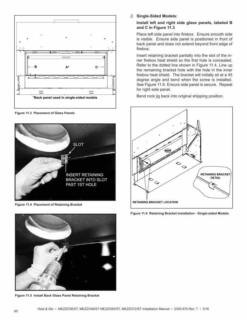
60Heat & Glo • MEZZO36/ST, MEZZO48/ST MEZZO60/ST, MEZZO72/ST Installation Manual • 2300-970 Rev. T • 3/16
Figure 11.6 Retaining Bracket Installation - Single-sided Models
RETAINING BRACKET LOCATION
RETAINING BRACKETDETAIL
Figure 11.3 Placement of Glass Panels
A*B C
*Back panel used in single-sided models
Figure 11.5 Install Back Glass Panel Retaining Bracket
Figure 11.4 Placement of Retaining Bracket
2. Single-Sided Models: Install left and right side glass panels, labeled B
and C in Figure 11.3 Place left side panel into fi rebox. Ensure smooth side
is visible. Ensure side panel is positioned in front of back panel and does not extend beyond front edge of fi rebox.
Insert retaining bracket partially into the slot of the in-ner fi rebox heat shield so the fi rst hole is concealed. Refer to the dotted line shown in Figure 11.4. Line up the remaining bracket hole with the hole in the inner fi rebox heat shield. The bracket will initially sit at a 45 degree angle and bend when the screw is installed. See Figure 11.6. Ensure side panel is secure. Repeat for right side panel.
Bend rock jig back into original shipping position.
SLOTSLOT
INSERT RETAINING INSERT RETAINING BRACKET INTO SLOTBRACKET INTO SLOTPAST 1ST HOLEPAST 1ST HOLE

61Heat & Glo • MEZZO36, MEZZO36ST, MEZZO48, MEZZO48ST Installation Manual • 2300-970 Rev. T • 3/16
Figure 11.7 Retaining Bracket Installation - See-Through Models
RETAINING BRACKET LOCATION
RETAINING BRACKETDETAIL
E. Install Media A media kit is available for use with the MEZZO models. Install rock media according to instructions included with media kit.
F. Install Log Set An optional log set is available for use with the MEZZO mod-els. Install the log set per instructions included with kit.
3. See-Through Models: Install left and right side glass panels, labeled B
and C in Figure 11.3 Place left side panel into fi rebox with smooth side vis-
ible. Ensure side panel does not extend beyond front edge of fi rebox. Place retaining bracket over glass panel so holes in the bracket are against the fi rebox side. Use two self-drilling screws to secure the brack-et to the fi rebox sides. See Figure 11.7. Ensure side panel is secure. Repeat for right side panel.

62Heat & Glo • MEZZO36/ST, MEZZO48/ST MEZZO60/ST, MEZZO72/ST Installation Manual • 2300-970 Rev. T • 3/16
12 12 Reference Materials
A. Vent Components Diagrams
10-1/2 in.(267 mm)
10-7/8 in.(276 mm)
45°
7-3/8 in.(187 mm)
11-3/8 in.(289 mm)
1-1/4 in. (32 mm)
9-1/4 in.(235 mm)
13-1/4 in.(337 mm)
1/2 in. TYP
DVP90ST (90° Elbow)
10 in.(254 mm)
10 in.(254 mm)
1 in.(25 mm)
12 in.(305 mm)
14 in.(356 mm)
1 in.(25 mm)
8 in.(203 mm)
6 in.(152 mm)
10 in.(254 mm)
1- 1/2 in.(38 mm)
5 in.(127 mm)
12 in.(305 mm)
UP
DVP-HVS (Vent Support) DVP-WS (Wall Shield Firestop)
DVP-FS (Ceiling Firestop)
DVP45 (45º Elbow)DVP Pipe (see chart)
EffectiveHeight/Length
4-7/8 in.( 276 mm)
(13 mm)
Finished Height: 19-3/4 in./502 mmUNIV-AS2 (Attic Insulation Shield)
Tab=1 in.(25.4 mm)
20-3/4 in.(527 mm)
Pipe Effective LengthInches Millimeters
DVP4 4 102
DVP6 6 152
DVP12 12 305
DVP24 24 610
DVP36 36 914
DVP48 48 1219
DVP6A 3 to 6 76 to 152
DVP12A 3 to 12 76 to 305
Figure 12.1 DVP Vent Components
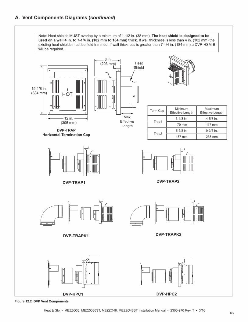
63Heat & Glo • MEZZO36, MEZZO36ST, MEZZO48, MEZZO48ST Installation Manual • 2300-970 Rev. T • 3/16
A. Vent Components Diagrams (continued)
Figure 12.2 DVP Vent Components
DVP-HPC1 DVP-HPC2
DVP-TRAP1 DVP-TRAP2
DVP-TRAPK2DVP-TRAPK1
DVP-TRAPHorizontal Termination Cap
15-1/8 in.(384 mm)
12 in.(305 mm)
8 in.(203 mm)
MaxEffectiveLength
Note: Heat shields MUST overlap by a minimum of 1-1/2 in. (38 mm). The heat shield is designed to be used on a wall 4 in. to 7-1/4 in. (102 mm to 184 mm) thick. If wall thickness is less than 4 in. (102 mm) the existing heat shields must be field trimmed. If wall thickness is greater than 7-1/4 in. (184 mm) a DVP-HSM-B will be required.
HeatShield
Term Cap MinimumEffective Length
MaximumEffective Length
Trap13-1/8 in. 4-5/8 in.
79 mm 117 mm
Trap25-3/8 in. 9-3/8 in.
137 mm 238 mm

64Heat & Glo • MEZZO36/ST, MEZZO48/ST MEZZO60/ST, MEZZO72/ST Installation Manual • 2300-970 Rev. T • 3/16
A. Vent Components Diagrams (continued)
Figure 12.3 DVP Vent Components
13-1/4 in.(337 mm)
24-5/8 in.(625 mm)
27-1/2 in.(699 mm)
RF6MRoof Flashing Multi-pak
31 in.(787 mm)
24-5/8 in.(625 mm)
13-1/4 in.(337 mm)
RF12MRoof Flashing Multi-pak
Cap ShieldDRC-RADIUS
13-7/8 in.(352 mm)
9-1/2 in.(241 mm)
14 in.(356 mm)
COOL-ADDMCap Shield
11-5/8 in.(295 mm)
5-3/4 in.(146 mm)
7-1/8 in.(181 mm)
12-1/8 in.(308 mm)
DVP-BEK2DVP-HPC Cap Brick Extension
13-7/8 in.(352 mm)
5 in.(127 mm)
11-7/8 in.(302 mm)
DVP-TRAPFL Flashing
26 in.660 mm
DVP-HSM-BExtended Heat Shield
12 IN.(305 mm)
7 IN.(178 mm)
4-15/16 IN.
A A A
1/2 IN.(13 mm)
7/8 IN.(22 mm)
(125 mm)
7 IN.(178 mm)
TRAP-VSSVinyl Siding Shield

65Heat & Glo • MEZZO36, MEZZO36ST, MEZZO48, MEZZO48ST Installation Manual • 2300-970 Rev. T • 3/16
A. Vent Components Diagrams (continued)
Figure 12.4 DVP Vent Components
7-1/4 in.
12 in.305 mm
(184 mm)
5-1/4 in.(133 mm)
12-1/2 in.(318 mm)
DVP-TVHWVerticalTermination Cap (Highwind)
1 in.(25 mm)
14 in.(356 mm)
3/8 in. (10 mm)1 in. (25 mm)
7-1/4 in.(184 mm)
7-3/4 to 10-3/8 in.(197 to 264 mm)
DVP-FBHTFireBrickTermination Cap
14 in.(356 mm)
12 in.(305 mm)
12-1/8 in.(314 mm)
7-1/8 in.(181 mm)
8-3/4 in.(222 mm)
1-5/8 in.(41 mm)
16-7/8 in.(429 mm)
DVP-HPCHigh Performance Cap
DVP-TB1Basement Vent Cap
12 in.(305 mm)
1-1/2 in.(38 mm)
7-3/8 in.(187 mm)
14 in.(356 mm)
17-3/4 in.(451 mm)
6 in.152 mm
13 in.(330 mm)
15 in.(381 mm)
8-1/8 in.(206 mm)
DVP-HRC-SS
10-7/8 in.276 mm
10-1/2 in.267 mm
3°87°
Effective Length5-3/4 to 8-3/8 in.146 to 213 mm
5-1/2 in.140 mm
8-3/8 in.213 mm
DVP-HRC-ZC-SS

66Heat & Glo • MEZZO36/ST, MEZZO48/ST MEZZO60/ST, MEZZO72/ST Installation Manual • 2300-970 Rev. T • 3/16
Optional Wire HarnessDESCRIPTION PART NUMBER
10 ft. PV Wire Harness PVI-WH1020 ft. PV Wire Harness PVI-WH2040 ft. PV Wire Harness PVI-WH4060 ft. PV Wire Harness PVI-WH6080 ft. PV Wire Harness PVI-WH80100 ft. PV Wire Harness PVI-WH100
PVI-SLPPower Vent Inline
Note: Wire harnesses required to power the PVI-SLP connect to the appliance and are ordered separately from PVI-SLP. Contact your dealer to order.
12-1/2 IN.318 mm
20-3/4 IN.527 mm
13-5/8 IN.346 mmEFFECTIVE LENGTH
32 IN. (813 mm) MIN.35 IN. (889 mm) MAX.
Note: Use only approved termination caps with the PVI-SLP. See instructions included with PVI-SLP kit.
Figure 12.5 PVI-SLP Vent Components
16 IN.406 mm
15 IN.(381 mm)
16-11/16 IN.(424 mm)
9-3/16 IN.(233 mm)
4-1/2 IN.114 mm
16-11/16 IN.424 mm
13-5/8 IN.(346 mm)
12-1/2 IN.(318 mm)
SLP-LPCSLP Low Profi le Cap
17-7/8 IN.454 mm
7-3/8 IN.187 mm
14 IN.356 mm
12 IN.305 mm
SLP-TB1Basement Vent Cap
Note: SLP-LPC, SL-2DVP and DVP-2SL components must be accompanied by a PVI-SLP.
SL-2DVPAdapter
3-15/16 in.(101 mm)
6-11/16 in.(169 mm)
8 in.(203 mm)
3-15/16 in.(101 mm)
3-13/16 in.(97 mm)
5-1/16 in.(128 mm)
6-3/8 in.163 mm
4-3/16 in.106 mm
4-5/8 in.117 mm
5-1/16 in.128 mm
8-1/8 in.206 mm
DVP-2SLAdapter
4 in.102 mm
A. Vent Components Diagrams (continued)
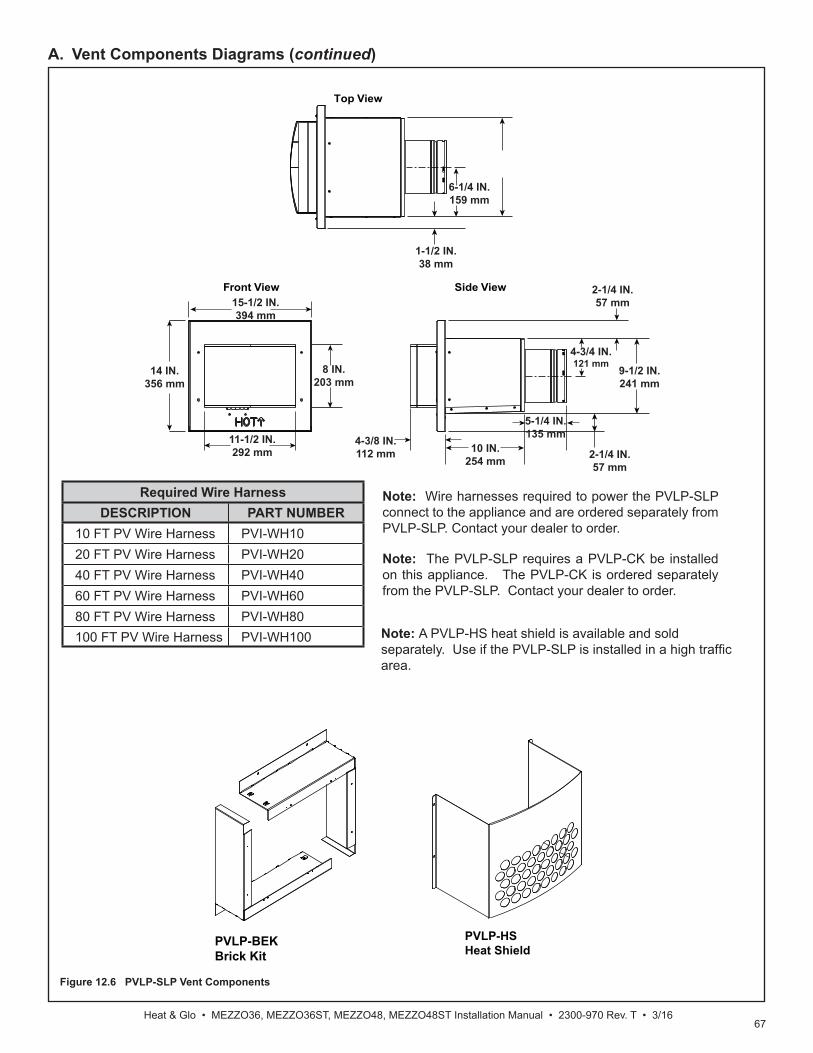
67Heat & Glo • MEZZO36, MEZZO36ST, MEZZO48, MEZZO48ST Installation Manual • 2300-970 Rev. T • 3/16
Required Wire HarnessDESCRIPTION PART NUMBER
10 FT PV Wire Harness PVI-WH1020 FT PV Wire Harness PVI-WH2040 FT PV Wire Harness PVI-WH4060 FT PV Wire Harness PVI-WH6080 FT PV Wire Harness PVI-WH80100 FT PV Wire Harness PVI-WH100
Note: Wire harnesses required to power the PVLP-SLP connect to the appliance and are ordered separately from PVLP-SLP. Contact your dealer to order.
Note: The PVLP-SLP requires a PVLP-CK be installed on this appliance. The PVLP-CK is ordered separately from the PVLP-SLP. Contact your dealer to order.
Figure 12.6 PVLP-SLP Vent Components
PVLP-HSHeat Shield
14 IN.356 mm
15-1/2 IN.394 mm
11-1/2 IN.292 mm
8 IN.203 mm
4-3/8 IN.112 mm 10 IN.
254 mm
5-1/4 IN.135 mm
2-1/4 IN.57 mm
9-1/2 IN.241 mm
4-3/4 IN.121 mm
2-1/4 IN.57 mm
1-1/2 IN.38 mm
6-1/4 IN.159 mm
Front View
Top View
Side View
Note: A PVLP-HS heat shield is available and sold separately. Use if the PVLP-SLP is installed in a high traffi c area.
PVLP-BEKBrick Kit
A. Vent Components Diagrams (continued)

68Heat & Glo • MEZZO36/ST, MEZZO48/ST MEZZO60/ST, MEZZO72/ST Installation Manual • 2300-970 Rev. T • 3/16
B. AccessoriesRemote Controls, Wall Controls and WallSwitchesFollow the instructions supplied with the control installed to operate your fi replace:For safety:• Install a switch lock or a wall/remote control with child
protection lockout feature.• Keep remote controls out of reach of children.Contact your dealer if you have questions.
Printed in U.S.A. - Copyright 2016
Heat & Glo, a brand of Hearth & Home Technologies 7571 215th Street West, Lakeville, MN 55044
www.heatnglo.com
Please contact your Heat & Glo dealer with any questions or concerns. For the location of your nearest Heat & Glo dealer,
please visit www.heatnglo.com.
Optional Heat-Zone® KitFollow the instruction supplied with the kit for operation.• Preparation for installation of Heat-Zone® Kit is discussed
in Section 5.E.Contact your dealer if you have questions.