Owner’s Manual - Hearth N Homedownloads.hearthnhome.com/installManuals/7021_155.pdf · manner...
32
1 7021-155D May 12, 2017 NOTICE: DO NOT DISCARD THIS MANUAL CASTILE-B PELLET APPLIANCE Model(s): CASTILE-MBK-B CASTILE-CWL-B CASTILE-CSB-B CASTILE-PMH-B O-T L Tested and Listed by Portland Oregon USA OMNI-Test Laboratories, Inc. C US Owner’s Manual Operation & Care INSTALLER: Leave this manual with party responsible for use and operation. OWNER: Retain this manual for future reference. Contact your dealer with questions on installation, operation, or service. WARNING If the information in these instruc- tions is not followed exactly, a fire could result causing property damage, personal injury, or death. • Do not store or use gasoline or other flam- mable vapors and liquids in the vicinity of this or any other appliance. • Do not over fire - If appliance or chimney connector glows, you are over firing. Over firing will void your warranty. • Comply with all minimum clearances to combustibles as specified. Failure to comply may cause house fire. HOT SURFACES! Glass and other surfaces are hot during operation AND cool down. Hot glass will cause burns. • Do not touch glass until it is cooled • NEVER allow children to touch glass • Keep children away • CAREFULLY SUPERVISE children in same room as fireplace. • Alert children and adults to hazards of high temperatures • High temperatures may ignite clothing or other flammable materials. • Keep clothing, furniture, draperies and other flammable materials away. WARNING CAUTION Tested and approved for wood pellets and shelled corn only. Burning of any other type of fuel voids your warranty. NOTE To obtain a French translation of this manual, please contact your dealer or visit www.quadrafire.com Pour obtenir une traduction française de ce manuel, s’il vous plaît contacter votre revendeur ou visitez www.quadrafire.com CAUTION Check building codes prior to installation. • Installation MUST comply with local, regional, state and na- tional codes and regulations. • Consult local building, fire officials or authorities having juris- diction about restrictions, installation inspection, and permits. Installation and service of this appliance should be performed by qualified personnel. Hearth & Home Technologies recommends HHT Factory Trained or NFI certified professionals.
Transcript of Owner’s Manual - Hearth N Homedownloads.hearthnhome.com/installManuals/7021_155.pdf · manner...

1 7021-155D May 12, 2017
NOTICE: DO NOT DISCARD THIS MANUAL
CASTILE-B PELLET APPLIANCE
Model(s):CASTILE-MBK-B CASTILE-CWL-BCASTILE-CSB-B CASTILE-PMH-B
O-T LTested and Listed by
PortlandOregon USA
OMNI-Test Laboratories, Inc.C US
Owner’s ManualOperation & Care
INSTALLER: Leave this manual with party responsible for use and operation. OWNER: Retain this manual for future reference.
Contact your dealer with questions on installation, operation, or service.
WARNING
If the information in these instruc-tions is not followed exactly, a fire could result causing property damage, personal injury, or death.
• Donotstoreorusegasolineorotherflam-mablevaporsandliquidsinthevicinityofthis or any other appliance.
• Donotoverfire-Ifapplianceorchimneyconnectorglows,youareoverfiring.Overfiringwillvoidyourwarranty.
• Complywithallminimumclearancestocombustiblesasspecified.Failuretocomplymaycausehousefire.
HOT SURFACES! Glassandothersurfacesarehot during operation AND cool down.
Hot glass will cause burns.• Do not touch glass until it is cooled• NEVER allow children to touch glass• Keep children away• CAREFULLY SUPERVISE children in same room as
fireplace.• Alertchildrenandadultstohazardsofhightemperatures• High temperatures may ignite clothing or other
flammable materials.• Keep clothing, furniture, draperies andother flammable
materialsaway.
WARNING
CAUTIONTestedandapprovedforwoodpelletsandshelledcornonly.Burningofanyothertypeoffuelvoidsyourwarranty.
NOTEToobtainaFrenchtranslationofthismanual,pleasecontactyourdealerorvisitwww.quadrafire.com
Pourobtenirunetraductionfrançaisedecemanuel,s’ilvousplaîtcontactervotrerevendeurouvisitezwww.quadrafire.com
CAUTIONCheckbuildingcodespriortoinstallation.• InstallationMUSTcomplywithlocal,regional,stateandna-
tional codes and regulations.• Consultlocalbuilding,fireofficialsorauthoritieshavingjuris-
dictionaboutrestrictions,installationinspection,andpermits.
Installation and service of this appliance should be performed by qualified personnel. Hearth & Home Technologies recommends HHT Factory Trained or NFI certified professionals.

2 7021-155D May 12, 2017
CASTILE FREESTANDING
Report / Rapport:061-S-77d-6.2
DO NOT REMOVE THIS LABEL /NE PAS ENLEVER L'ETIQUETTEMade in U.S.A. of US and imported parts.
Fabriqué aux États-Unis-d'Amérique par des piècesd'origine américaine et pièces importées. 7021-150E
JAN JUNFEB MAR APR MAY
JUL DECAUG SEP OCT NOV
2015 2016 2017
U.S. ENVIRONMENTAL PROTECTION AGENCYCertified to comply with 2015 particulate emissions standards at 1.8 G/HR EPA Method 28 &
5G. Not approved for sale after May 15,2020.
This wood heater needs periodic and repair for proper operation. Consult the owner’s manual for further information. It is against federal regulations to operate this wood heater in a
manner inconsistent with the operation instructions in the owner’s manual
CAUTION: HOT WHILE IN OPERATION DO NOT TOUCH, KEEP CHILDREN, CLOTHING AND FURNITURE AWAY. CONTACT MAY CAUSE SKIN BURNS. SEE NAMEPLATE AND INSTRUCTIONS. Operate this unit only with fuel hopper lid closed. Failure to do so may result in emissions of products of combustion from the hopper under certain conditions. Maintain hopper seal in good condition. Do not over fill the hopper.ATTENTION: CHAUD LORS DE L'OPÉRATION. NE PAS TOUCHER. GARDEZ LES ENFANTS ET LES VÊTEMENTS
LOIN DE L'ESPACE DÉSIGNÉ DE L'INSTALLATION. LE CONTACT PEUT CAUSER DES BRÛLURES À LA PEAU. VOIR L'ÉTIQUETTE ET LES INSTRUCTIONS. Opérez cet appareil uniquement avec le couvercle de la trémie fermé. Le défaut de ne pas suivre les instructions peut résulter, sous certaines conditions, en une combustion des émissions des produits venant de la trémie. Ne pas remplir la trémie trop pleine. 7014-197C
HEARTH & HOME TECHNOLOGIES13-1923
007014
7021-131D
Report / Rapport061-S-77d-6.2
A. Sample of Serial Number / Safety LabelLOCATION:BackofAppliance
SerialNo.
Mfg.Date
S A M P L E
TestLab&Report No.
Model Name
NOTE: Clearances may only be reduced by means approved by the regulatory authority having jurisdiction
and Welcome to the Quadra-Fire Family!

May 12, 2017 7021-155D 3
CASTILE FREESTANDING
TABLE OF CONTENTS
Safety Alert Key:• DANGER! Indicatesahazardoussituationwhich,ifnotavoidedwillresultindeathorseriousinjury.• WARNING!Indicatesahazardoussituationwhich,ifnotavoidedcouldresultindeathorseriousinjury.• CAUTION! Indicatesahazardoussituationwhich,ifnotavoided,couldresultinminorormoderateinjury.• NOTICE:Indicatespracticeswhichmaycausedamagetotheapplianceortoproperty.
A.SampleofSerialNumber/SafetyLabel............................2B.WarrantyPolicy ..................................................................4
1 Listing and Code Approvals ............. 7A.ApplianceCertification ......................................................7B.BTU&EfficiencySpecifications........................................7C.GlassSpecifications .........................................................7D. Electrical Rating................................................................7E.MobileHomeApproved .................................................... 7
2 Operating Instructions ...................... 8A.FireSafety .........................................................................8B. Non-CombustibleMaterials ..............................................8C.CombustibleMaterials .......................................................8D.FuelMaterialandFuelStorage ........................................8E. GeneralOperatingInformation .........................................9F.BeforeYourFirstFire ........................................................9G.StartingYourFirstFire .....................................................9H.FireCharacteristics ...........................................................10I.FeedRateAdjustmentInstructions ....................................10J. IgnitionCycles ...................................................................10K.ClearSpace ......................................................................11L.FrequentlyAskedQuestions .............................................11
3 Maintenance and Service ................ 12A.ProperShutdownProcedure ............................................12B.QuickReferenceMaintenanceChart................................12C. General Maintenance and Cleaning .................................13D.HighAshFuelContentMaintenance .................................15E.SootorCreosoteFire ........................................................16F.ThermostatBatteryInstallation,Replacement, andOperation ...................................................................16
4 Troubleshooting Guide .................... 175 Service Parts Replacement ............. 20
A.GlassReplacement-DoorAssembly ...............................20B.IgniterReplacement..........................................................20C.BlowerReplacement ........................................................21D.Baffle&BrickSetRemoval ..............................................22
6 Reference Materials ......................... 23A.ComponentFunctions.......................................................23B.ComponentLocations ........................................................25C. Exploded Drawings............................................................26D.ServiceParts .....................................................................27

4 7021-155D May 12, 2017
CASTILE FREESTANDING
B. Warranty PolicyHearth & Home Technologies
LIMITED LIFETIME WARRANTY
Hearth & Home Technologies, on behalf of its hearth brands (“HHT”), extends the following warranty for HHT gas, wood, pellet and electric hearth appliances that are purchased from an HHT authorized dealer.
WARRANTY COVERAGE:HHT warrants to the original owner of the HHT appliance at the site of installation, and to any transferee taking ownership of the appliance at the site of installation within two years following the date of original purchase, that the HHT appliance will be free from defects in materials and workmanship at the time of manufacture. After installation, if covered compo-nents manufactured by HHT are found to be defective in materials or workmanship during the applicable warranty period, HHT will, at its option, repair or replace the covered components. HHT, at its own discretion, may fully discharge all of its obligations under such warranties by replacing the product itself or refunding the verified purchase price of the product itself. The maximum amount recoverable under this warranty is limited to the purchase price of the product. This warranty is subject to conditions, exclusions and limitations as described below.
WARRANTY PERIOD:Warranty coverage for consumers begins at the date of installation. In the case of new home construction, warranty coverage begins on the date of first occupancy of the dwelling or six months after the sale of the product by an indepen-dent, authorized HHT dealer/distributor, whichever occurs earlier. However, the warranty shall commence no later than 24 months following the date of product shipment from HHT, regardless of the installation or occupancy date. The warranty period for parts and labor for covered components is produced in the following table.The term “Limited Lifetime” in the table below is defined as: 20 years from the beginning date of warranty coverage for gas appliances, and 10 years from the beginning date of warranty coverage for wood and pellet appliances. These time periods reflect the minimum expected useful lives of the designated components under normal operating conditions.
Warranty Period HHT Manufactured Appliances and Venting
Parts Labor Gas (Indoor)
Gas/Wood (Outdoor
Protected) * Pellet Wood Electric Venting Components Covered
1 Year X X X X X X All parts and material except as covered by Conditions, Exclusions, and Limitations listed
2 Years
X X Igniters, auger motors, electronic components, and glass
X X X Factory-installed blowers X Molded refractory panels X Ignition Modules
3 Years X Firepots, burn pots, mechanical feeders/auger assemblies
5 Years 1 Year X Vent Free burners, Vent Free ceramic fiber logs, Aluminized Burners
X X Castings and Baffles
6 Years 3 Years X Catalyst - limitations listed
7 Years 3 Years X X Manifold tubes, HHT chimney and termination
10 Years 1 Year X Burners, logs and refractory
Limited Lifetime 3 Years X X X
Firebox and heat exchanger, Grate and Stainless Steel Burners, FlexBurn® System (engine, inner cover,
access cover, and fire back)
90 Days X X X X X X All replacement parts beyond warranty period
* Not designed for direct outdoor environment, see HHT Outdoor products. When installed outdoors, installation must strictly follow HHT Outdoor Protected Outdoor Applications Guidelines available from HHT Authorized Dealers.
May 12, 2017 7021-155D 5
CASTILE FREESTANDING
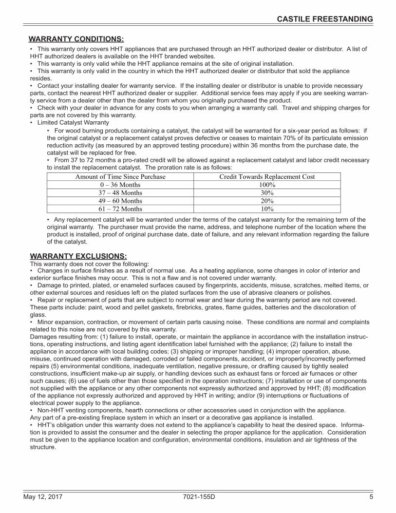
Amount of Time Since Purchase Credit Towards Replacement Cost 0 – 36 Months 100% 37 – 48 Months 30% 49 – 60 Months 20% 61 – 72 Months 10%
• This warranty only covers HHT appliances that are purchased through an HHT authorized dealer or distributor. A list of HHT authorized dealers is available on the HHT branded websites.• This warranty is only valid while the HHT appliance remains at the site of original installation.• This warranty is only valid in the country in which the HHT authorized dealer or distributor that sold the appliance resides.• Contact your installing dealer for warranty service. If the installing dealer or distributor is unable to provide necessary parts, contact the nearest HHT authorized dealer or supplier. Additional service fees may apply if you are seeking warran-ty service from a dealer other than the dealer from whom you originally purchased the product. • Check with your dealer in advance for any costs to you when arranging a warranty call. Travel and shipping charges for parts are not covered by this warranty.• Limited Catalyst Warranty
WARRANTY CONDITIONS:
• For wood burning products containing a catalyst, the catalyst will be warranted for a six-year period as follows: if the original catalyst or a replacement catalyst proves defective or ceases to maintain 70% of its particulate emission reduction activity (as measured by an approved testing procedure) within 36 months from the purchase date, the catalyst will be replaced for free.• From 37 to 72 months a pro-rated credit will be allowed against a replacement catalyst and labor credit necessary to install the replacement catalyst. The proration rate is as follows:
• Any replacement catalyst will be warranted under the terms of the catalyst warranty for the remaining term of the original warranty. The purchaser must provide the name, address, and telephone number of the location where the product is installed, proof of original purchase date, date of failure, and any relevant information regarding the failure of the catalyst.
WARRANTY EXCLUSIONS:This warranty does not cover the following:• Changes in surface finishes as a result of normal use. As a heating appliance, some changes in color of interior and exterior surface finishes may occur. This is not a flaw and is not covered under warranty.• Damage to printed, plated, or enameled surfaces caused by fingerprints, accidents, misuse, scratches, melted items, or other external sources and residues left on the plated surfaces from the use of abrasive cleaners or polishes.• Repair or replacement of parts that are subject to normal wear and tear during the warranty period are not covered. These parts include: paint, wood and pellet gaskets, firebricks, grates, flame guides, batteries and the discoloration of glass. • Minor expansion, contraction, or movement of certain parts causing noise. These conditions are normal and complaints related to this noise are not covered by this warranty.Damages resulting from: (1) failure to install, operate, or maintain the appliance in accordance with the installation instruc-tions, operating instructions, and listing agent identification label furnished with the appliance; (2) failure to install the appliance in accordance with local building codes; (3) shipping or improper handling; (4) improper operation, abuse, misuse, continued operation with damaged, corroded or failed components, accident, or improperly/incorrectly performed repairs (5) environmental conditions, inadequate ventilation, negative pressure, or drafting caused by tightly sealed constructions, insufficient make-up air supply, or handling devices such as exhaust fans or forced air furnaces or other such causes; (6) use of fuels other than those specified in the operation instructions; (7) installation or use of components not supplied with the appliance or any other components not expressly authorized and approved by HHT; (8) modification of the appliance not expressly authorized and approved by HHT in writing; and/or (9) interruptions or fluctuations of electrical power supply to the appliance.• Non-HHT venting components, hearth connections or other accessories used in conjunction with the appliance.Any part of a pre-existing fireplace system in which an insert or a decorative gas appliance is installed.• HHT’s obligation under this warranty does not extend to the appliance’s capability to heat the desired space. Informa-tion is provided to assist the consumer and the dealer in selecting the proper appliance for the application. Consideration must be given to the appliance location and configuration, environmental conditions, insulation and air tightness of the structure.

6 7021-155D May 12, 2017
CASTILE FREESTANDING
This warranty is void if:• The appliance has been over-fired, operated in atmospheres contaminated by chlorine, fluorine, or other damaging chemicals. Over-firing can be identified by, but not limited to, warped plates or tubes, deformation/warping of interior cast iron structure or components, rust colored cast iron, bubbling, cracking and discoloration of steel or enamel finishes. • The appliance is subjected to prolonged periods of dampness or condensation.• There is any damage to the appliance or other components due to water or weather damage which is the result of, but not limited to, improper chimney or venting installation.
LIMITATIONS OF LIABILITY:• The owner’s exclusive remedy and HHT’s sole obligation under this warranty, under any other warranty, express or implied, or in contract, tort or otherwise, shall be limited to replacement, repair, or refund, as specified above. In no event will HHT be liable for any incidental or consequential damages caused by defects in the appliance. Some states do not allow exclusions or limitation of incidental or consequential damages, so these limitations may not apply to you. This warranty gives you specific rights; you may also have other rights, which vary from state to state. EXCEPT TO THE EXTENT PROVIDED BY LAW, HHT MAKES NO EXPRESS WARRANTIES OTHER THAN THE WAR-RANTY SPECIFIED HEREIN. THE DURATION OF ANY IMPLIED WARRANTY IS LIMITED TO DURATION OF THE EXPRESSED WARRANTY SPECIFIED ABOVE.

May 12, 2017 7021-155D 7
CASTILE FREESTANDING
Model CastilePelletApplianceLaboratory OMNITestLaboratories,Inc.Report No. 061-S-77d-6.2Type SolidFuelRoomAppliance/PelletFuel
Burning TypeStandard ASTME1509-04,ULCS627-00and
ULC/ORD-C1482-M1990RoomAppli-ancePelletFuelBurningtypeand(UM)84-HUD,MobileHomeApproved.
FCC ComplieswithPart15ofFCCRules.Operationissubjecttothefollowingtwoconditions:(1)thisdevicemaynotcauseharmfulinterference,and(2)thisdevicemustacceptanyinterferencereceived,includinginterferencethatmaycause undesired operation.
1 Listing and Code Approvals
A. Appliance Certification
NOTE:Hearth&HomeTechnologies,manufacturerofthis appliance, reserves the right to alter its products, their specificationsand/orpricewithoutnotice.
Improper installation, adjustment, alteration, service ormaintenancecancauseinjuryorpropertydamage.Forassistanceoradditionalinformation,consultaqualifiedinstaller, service agency or your dealer.
Quadra-FireisaregisteredtrademarkofHearth&HomeTechnologies.
• Installationanduseofanydamagedappliance.• Modificationoftheappliance.• Installation other than as instructed by Hearth & Home
Technologies.• Installationand/oruseofanycomponentpartnotapprovedby
Hearth&HomeTechnologies.• Operatingappliancewithoutfullyassemblingallcomponents.• Operating appliancewithout legs attached (if suppliedwith
appliance).• DoNOTOverfire-Ifapplianceorchimneyconnectorglows,
youareoverfiring.Anysuchactionthatmaycauseafirehazard.
WARNINGFire Risk.Hearth&HomeTechnologiesdisclaimsanyresponsibilityfor,andthewarrantywillbevoidedby,thefollowingactions:
B. BTU & Efficiency Specifications
C. Glass SpecificationsThisapplianceisequippedwith5mmceramicglass.Replaceglassonlywith5mmceramicglass.Pleasecon-tactyourdealerforreplacementglass.D. Electrical Rating115VAC,60Hz,Start5Amps,Run1.25Amps
E. Mobile Home Approved • Thisapplianceisapprovedformobilehomeinstalla-
tionswhennotinstalledinasleepingroomandwhenanoutsidecombustionairinletisprovided.
• Thestructuralintegrityofthemobilehomefloor,ceil-ing,andwallsmustbemaintained.
• The appliance must be properly grounded to theframeofthemobilehomeanduseonlyListedpelletventClass“L”or“PL”connectorpipe.
• OutsideAirKit,partOAK-ACCmustbeinstalledinamobilehomeinstallation.NOTICE: Thisinstallationmustconformwithlocalcodes.In
theabsenceoflocalcodesyoumustcomplywiththeASTM E1509-04, ULC S627-00, (UM) 84-HUD and ULC/ORD-C-1482.
EPACertification#: 940-14EPACertifiedEmissions: 1.8gramsperhour*LHVTestedEfficiency: N/A**HHVTestedEfficiency: N/A
***EPABTUOutput: 8,500to28,200/hr.****BTUInput: 11,600to38,700/hr.
VentSize: 3or4inches,LorPLHopperCapacity: 40lbs.+/-5lbs.
Fuel WoodPellets*WeightedaverageLHVefficiencyusingdatacollectedduringEPAemissionstest.**WeightedaverageHHVefficiencyusingdatacollectedduringEPAemissionstest.***ArangeofBTUoutputsbasedonEPADefaultEfficiencyandtheburnratesfromthelowandhighEPAtests.****Based on the maximum feed rate per hour multiplied byapproximately8600BTU’swhich is theaverageBTU’s fromapoundofpellets.
TheQuadra-FireCastilePelletAppliancemeets theU.S.EnvironmentalProtectionAgency’semissionlimitsforpelletappliancessoldafterMay15,2015.
Thispelletapplianceneedsperiodicinspectionandrepairforproperoperation.Itisagainstfederalregulationstooperatethispelletapplianceinamannerinconsistentwithoperatinginstructionsinthismanual.

8 7021-155D May 12, 2017
CASTILE FREESTANDING
User Guide2 Operating Instructions
A. Fire SafetyToprovide reasonable fire safety, the following should begivenseriousconsideration:• InstallatleastonesmokedetectorandCO monitoroneachfloorofyourhome.
• Locatedetectorsawayfromtheheatingapplianceandcloseto the sleeping areas.
• Follow the detector’smanufacturer’s placement andinstallationinstructionsandmaintainregularly.
• ConvenientlylocateaClassAfireextinguishertocontendwithsmallfires.
• Intheeventofahopperfire: • Evacuatethehouseimmediately.
• Notifyfiredepartment.
B. Non-Combustible MaterialsMaterialwhichwillnotigniteandburn,composedofanycombinationofthefollowing:-Steel -Plaster -Glass -Tile-Brick -Iron -Slate -ConcreteMaterials reported as passing ASTM E 136, Standard Test Method for Behavior of Metals, in a Vertical Tube Furnace of 750° C.
C. Combustible MaterialsMaterialmadeof/orsurfacedwithanyofthefollowingmaterials:-CompressedPaper-Wood-Plywood/OSB-SheetRock(drywall)-Plastic-PlantFibersAnymaterialthatcanigniteandburn:flameproofedornot,plastered or non-plastered.
D. Fuel Material and Fuel StoragePelletfuelqualitycangreatlyfluctuate.This appliance has beendesignedtoburnawidevarietyoffuels,givingyouthechoicetousethefuelthatismosteconomicalinyourregion.Hearth&HomeTechnologiesstronglyrecommendsonlyusingPelletFuelInstitute(PFI)certifiedfuel.
FuelMaterial• Madefromsawdustorwoodby-products• Dependingonthesourcematerialitmayhaveahighor
low ash content.HigherAshContentMaterial• Hardwoodswithahighmineralcontent• Fuelthatcontainsbark• Standardgradepellets,highashpellets,LowerAshContentMaterial• Softwoods• Fuelswithlowmineralcontent• PremiumgradepelletsLowerAshContentMaterial• Moisturecontentmustbe15%orless• Cornmustbefreeofdebris.Neverburncornstraight
fromthefield.Itwillclogtheaugermechanism.• Cornwithexcessivegraindustmustbescreenedby
siftingwith3/16(4.76mm)inchmeshscreening• Do no sue corn that contains additives such as oils or
meansorhasbeenchemicallytreatedwithpesticides.Itwillvoidyourwarrantyanddestroytheexhaustsys-tem.
Fire Risk.• Donotoperateappliancebeforereading
and understanding operating instructions.• Failuretooperateapplianceproperlymay
causeahousefire.
WARNING
Do not burn fuel that contains an additive; (such as soybean oil). • Maycausehopperfires •Damagetoproductmayresult
Read the ingredients list on the package.
CAUTION!
ClinkersMineralsandothernon-combustiblematerialssuchassandwillturnintoahard,glass-likesubstancecalledaclinkerwhenheatedinthefirepot.Treesfromdifferentareaswillvaryinmineralcontent.Thatiswhysomefuelsproducemoreclinkersthanothers.MoistureAlwaysburndryfuel.Burningfuelwithhighmoisturecontenttakesheat from the fuel and tends to cool theappliance,robbingheatfromyourhome.Damppelletfuelcanclogthefeedsystem.Size• Pelletsareeither1/4inchor5/16inch(6-8mm)indiameter• Lengthshouldbenomorethat1-1/2inches(38mm)• Pellet lengths can vary from lot to lot from the same
manufacturer• Duetolengthvariations,theflameheight(feedrate)may
needadjustingoccasionally.Seepage 9 forinstructions.

May 12, 2017 7021-155D 9
CASTILE FREESTANDING
Performance• Higherashcontentrequirestheashdrawertobeemptied
morefrequently• Hardwoodsrequiremoreairtoburnproperly• Premiumwoodpelletsproducethehighestheatoutput.• Burningpelletslongerthan1-1/2inches(38mm)cancause
an inconsistentfuelfeedrateand/ormissedignitions.Werecommendthatyoubuyfuelinmulti-tonlotswheneverpossible.However,wedorecommendtryingvariousbrandsbeforepurchasingmulti-tonlotstoensureyoursatisfaction.ChangingtoDifferentFuelType• Emptythehopperofthepreviousfuel• ThoroughlyvacuumhopperbeforefillingwiththenewfuelThe burn rate, BTU content and heat outputwill all varydependingonthefuelselected.
Storage• Woodpelletsshouldbeleftintheiroriginalsealedbaguntilusingtopreventmoistureabsorption.
• Thiswillalsopreventrodentsfrombecomingaproblem.• Donotstoreanypelletfuelwithintheclearancerequirements
or in an area that would hinder routine cleaning and maintenance.
E. General Operating Information1. Thermostat Calls For HeatThe appliance is likemostmodern furnaces; when thethermostat calls forheat, yourappliancewill automaticallylightanddeliverheat.Whentheroomisuptotemperatureandthethermostatissatisfied,theredcalllightwillgooffandthe appliance will shut down.
Testedandapprovedforwoodpelletsandshelledcorn.Burningofanyothertypeoffuelvoidsyourwarranty.
CAUTION
Figure 9.1
2. Heat Output ControlsThis appliance is equipped with a heat output control switch thathasthreesettingsorburnrates;low,mediumandhigh.Theappliancewillturnonandoffasthethermostatdemands.Whenthethermostatcallsforheat,theappliancewillstartupattheburnrateforwhichitisset.Iftheapplianceissetatoneofthelowersettings,itwillrunquieterbuttakelongertoheatupanareathanifitweresetatahigherburnrate.Regardlessoftheburnrate,whentheareaiswarmenoughtosatisfythethermostat,theappliancewillshutoff.
F. Before Your First Fire1. First,make sure your appliance has been properly
installedandthatallsafetyrequirementshavebeenmet.Payparticularattentiontothefireprotection,ventingandthermostatinstallationinstructions.
2. Doublecheckthattheashdrawerandfireboxareempty!3. Closethefrontdoor.IMPORTANT DETAIL: The tip of the thermocouple must be in contact with the inside end of the thermocouple cover or missed ignitions can occur.
G. Starting Your First Fire1. A thermostat is required for proper operation of this
appliance,exceptforcorn.Atthistime,fillthehopperwithpellets,setthethermostattoitslowestsetting.Plugthepowercordintonearbyoutlet.
2. The exhaust blowerwill stay on for approximately 18minuteseventhoughthethermostatisnotcallingforheat.Thisisnormal.
3. Locate the heat output control switchmounted on thebackoftheapplianceintheupperrightcorner.Figure 9.1. Turn it to the “high”settingbypushing the topofthecontrolswitchinandthenadjustthethermostattoitshighestsetting.Removetherightsidepanelandtheredcalllightlocatedtotheleftofthecontrolboxwillbeon.Figure 10.2 on page 10.Thisindicatesthethermostatiscallingforheat.
4. Thefuelfeedsystemandtheignitershouldnow beon.5. Foryourfirstfireitwillbenecessarytopressthereset
buttononceapproximately2minutesafterstartupandagainin5minutes.Thiswillfillthefeedsystemandallowtheappliancetobegindroppingpellets.Theappliancewillcontinuetorunaslongasthethermostatiscallingforheat.
6. Oncetheappliancehasignited,letitburnforapproximately15minutes,thensetthethermostattothedesiredroomtemperature.Adjusttheheatoutputcontrolswitchtothedesired setting.
NOTE: We recommend theuseofa50-50blendofcornand wood pellets. The only change in operation is that the feedratemayrequireaslightadjustment.Iftheapplianceisrunningallofthetime,100%cornwillworkafterthefirehasbeenstartedusingwoodpellets.
HighMedLow
Heat Output Switch
Reset Button
Reset Button

10 7021-155D May 12, 2017
CASTILE FREESTANDING
HOT WHILE IN OPERATION. KEEP CHILDREN, CLOTHING AND FURNITURE AWAY. CONTACT MAY CAUSE SKIN BURNS.
CAUTION
H. Fire CharacteristicsAproperlyadjustedfirewiththeheatoutputcontrolswitchseton“high”hasashortactiveflamepatternthatextendsoutofthefirepotapproximately4inches(102mm).Ifthefirehas tallflameswithblack tailsandseemssomewhat lazy,thefeedratewillneedtobereduced.Thisisdonebyslidingthefueladjustmentcontrolroddown,whichwillreducethefeed.Ifthefireisnot4inches(102mm)tall,slidethefueladjustmentcontrolroduptoincreasethefeed.Amediumandlowsettingwillgiveashorterflame.Theflamewillriseandfallsomewhat.Thisisnormal.
I. Feed Rate Adjustment InstructionsThefeedadjustmentcontrolrodisfactoryset,andshouldbeadequateformostfuels.However,iftheflameheightistoohighortoolow,youwillneedtoadjustthefeedrate.Waituntiltheappliancehasbeenburningfor15minutesbeforemakingyouradjustmentsandallow15minutesforfeedadjustmenttotakeeffect.1. Loosen the set screw 1/4 to 1/2 turn during set-up of
appliance.Thiswillallowmovementofthefeedadjustmentcontrol rod. Do not re-tighten set screw. Figure 10.1
2.Loosenthewingnut.3. Adjustthefeedadjustmentcontrolrodupwardtowardsthe
“+”symboltoincreasethefeedrateandflameheightordowntowardsthe“-”symbol,todecreasethefeedrateandflameheight.
4. Re-tighten the wing nut.
Figure 10.2
Fire RiskDoNOToperateappliance:• With appliance door open.•Firepotflooropen.• Cleaning slide plates open.
DoNOTstorefuel:• Closerthanrequiredclearancestocombustiblestoappli-
ance• Withinspacerequiredforloadingorashremoval.
WARNING
Figure 10.1
Red Call Light is located on top of Junction Box behind the Control Box.
Control Box
Thumb Screw
Set Screw
Feed Adjustment Control Rod
Increase
Decrease
J. Ignition Cycles1. Atthebeginningofeachignitioncycle,itisnormaltosee
somesmokeinthefirebox.Thesmokewillstoponcethefirestarts.
2. Theconvectionblowerwillautomaticallyturnonafteryourappliancehasbeenburningforapproximately10minutes.Thisblowertransfersheatfromyourapplianceintotheroom,andwillcontinuetorunafterthethermostathasstoppedcalling forheatuntil theappliancehascooleddown.
3. Occasionallytheappliancemayrunoutoffuelandshutitselfdown.Whenthishappens,theredcalllightwillbeon. See Figure 10.2.Torestartit,fillthehopperandpresstheresetbutton.See Figure 9.1, page 9. When youpresstheresetbuttontheredcalllightwillgoout.Releasethebuttonandthelightwillcomebackon.Youshouldseeafireshortly.Ifnot,followtheinstructionsonpage 9,of“StartingYourFirstFire”.

May 12, 2017 7021-155D 11
CASTILE FREESTANDING
K. Clear SpaceMantel: Avoid placing candles and other heat-sensitive objectsonmantelorhearth.Heatmaydamagetheseobjects.
NOTICE: Clearances may only be reduced by means ap-proved by the regulatory authority having jurisdiction.
WARNINGFire RiskDoNOToperateappliance:• With appliance door open.•Withfirepotflooropen.
DoNOTstorefuel:• Closerthanrequiredclearancestocombustiblestoappli-
ance.• Withinspacerequiredforloadingorashremoval.
Fire Risk.Keepcombustiblematerials,gasolineandotherflammablevaporsandliquidsclearofappliance.•DoNOTstoreflammablematerialsintheappliance’svicinity.
• DO NOT USE GASOLINE, LANTERN FUEL, KEROSENE, CHARCOAL LIGHTER FLUID OR SIMILAR LIQUIDS TO START OR “FRESHEN UP” A FIRE IN THIS APPLIANCE.
• DO NOT BURN GARBAGE OR FLAMMABLE FLUIDS SUCH AS GASOLINE, NAPHTHA OR ENGINE OIL.
• DO NOT USE CHEMICALS OR FLUIDS TO START THE FIRE.
• Keepallsuchliquidswellawayfromtheappliancewhileitisin use.
• Combustiblematerialsmayignite.
WARNING
Fire Risk.DoNOTplacecombustibleobjectsinfrontoftheappliance. Hightemperaturesmayignitecloth-ing,furnitureordraperies.Maintainaminimumclearanceof3feet(914mm)infrontofappliance.
WARNING
L. Frequently Asked Questions
Odorsandvaporsreleasedduringinitialoperation.• Curingofhightemperaturepaint.• Openwindowsforaircirculation.
Odorsmaybeirritatingtosensitiveindividuals.
CAUTION
ISSUES SOLUTIONS1. Metallic noise. 1. Noiseiscausedbymetalexpandingandcontractingas
itheatsupandcoolsdown,similartothesoundpro-ducedbyafurnaceorheatingduct.Thisnoisedoesnotaffecttheoperationorlongevityofyourappliance.
2. Ashbuilduponglass. 2. Thisisnormal.Cleantheglass.
3. Glass has turned dirty. 3. Excessivebuildupofash.Thelowerburnsettingswillproducemoreash,thehigherburnsettingsproduceless.Themoreitburnsonlowthemorefrequentclean-ingoftheglassisrequired.
4. Firehastallflameswithblacktailsandislazy. 4. Thefeedrateneedstobereducedorthefirepotneedscleaning.Heatexchangerorexhaustblowerneedscleaning.
5. Smokeystart-uporpuffsofsmokefromtheairwash.
5. Eitherthefirepotisdirtyorthereistoomuchfuelatstart-upandnotenoughair.Closedownfeedrate1/4inchatatimeuntilthisnolongerhappens.
6. Largeflameatstart-up. 6. Thisisnormal.Flamewillsettledownoncethefireisestablished.
CONTACT YOUR DEALERforadditionalinformationregardingoperationandtroubleshooting.
Visit www.quadrafire.comtofindadealer.
12 7021-155D May 12, 2017
CASTILE FREESTANDING
3 Maintenance and Service
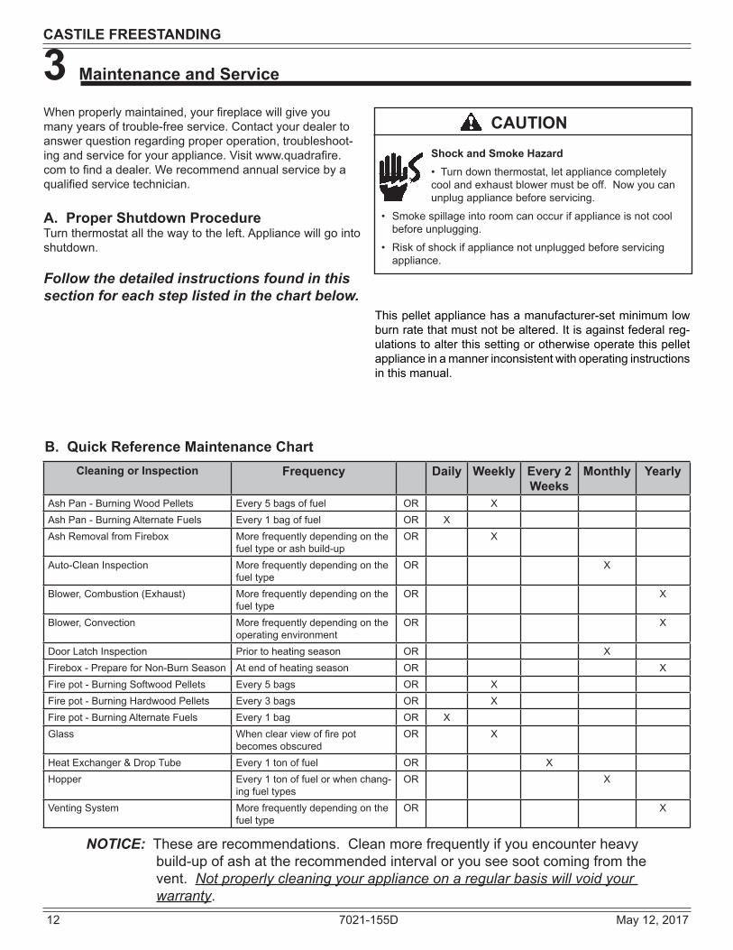
Whenproperlymaintained,yourfireplacewillgiveyoumanyyearsoftrouble-freeservice.Contactyourdealertoanswerquestionregardingproperoperation,troubleshoot-ingandserviceforyourappliance.Visitwww.quadrafire.comtofindadealer.Werecommendannualservicebyaqualifiedservicetechnician.
A. Proper Shutdown ProcedureTurnthermostatallthewaytotheleft.Appliancewillgointoshutdown.
Follow the detailed instructions found in this section for each step listed in the chart below.
B. Quick Reference Maintenance Chart
NOTICE: Thesearerecommendations.Cleanmorefrequentlyifyouencounterheavybuild-upofashattherecommendedintervaloryouseesootcomingfromthevent. Not properly cleaning your appliance on a regular basis will void your warranty.
Cleaning or Inspection Frequency Daily Weekly Every 2 Weeks
Monthly Yearly
AshPan-BurningWoodPellets Every5bagsoffuel OR XAshPan-BurningAlternateFuels Every1bagoffuel OR XAshRemovalfromFirebox Morefrequentlydependingonthe
fueltypeorashbuild-upOR X
Auto-CleanInspection Morefrequentlydependingonthefueltype
OR X
Blower,Combustion(Exhaust) Morefrequentlydependingonthefueltype
OR X
Blower, Convection Morefrequentlydependingontheoperatingenvironment
OR X
DoorLatchInspection Priortoheatingseason OR XFirebox-PrepareforNon-BurnSeason Atendofheatingseason OR XFirepot-BurningSoftwoodPellets Every5bags OR XFirepot-BurningHardwoodPellets Every3bags OR XFirepot-BurningAlternateFuels Every1bag OR XGlass Whenclearviewoffirepot
becomesobscuredOR X
HeatExchanger&DropTube Every1tonoffuel OR XHopper Every1tonoffuelorwhenchang-
ingfueltypesOR X
VentingSystem Morefrequentlydependingonthefueltype
OR X
Shock and Smoke Hazard•Turndownthermostat,letappliancecompletelycoolandexhaustblowermustbeoff.Nowyoucanunplugappliancebeforeservicing.
• Smokespillageintoroomcanoccurifapplianceisnotcoolbeforeunplugging.
• Riskofshockifappliancenotunpluggedbeforeservicingappliance.
CAUTION
Thispelletappliancehasamanufacturer-setminimumlowburnratethatmustnotbealtered.Itisagainstfederalreg-ulations to alter this setting or otherwise operate this pellet applianceinamannerinconsistentwithoperatinginstructionsinthismanual.

May 12, 2017 7021-155D 13
CASTILE FREESTANDING
C. General Maintenance and Cleaning1. Types of FuelDependingonthetypeoffuelyouareburningwilldictatehowoftenyouhavetocleanyourfirepot.Ifthefuelyouareburninghasahighdirtorashcontentoryouareburningshelledfieldcorn,itmaybenecessarytocleanthefirepotmorethanonceaday.Dirtyfuelwillcauseclinkerstoforminthefirepot.Aclinkerisformedwhendirt,ashoranon-burnablesubstanceisheatedto 2000°F(1093°C)andbecomesglass-like.Seepage 16 in thissectionformoredetailsonfuelswithhighashcontent.
2. Cleaning Fire pot with Cleaning Rod & Fire pot Scraper
• Frequency:Dailyormoreoftenasneeded• By:Homeowner a.Theappliancemustbeincompleteshutdownandcool
andtheexhaustbloweroff. Ifyouarejustcleaningthefirepot,thereisnoneedtounplugtheappliance.
b.Pull fire pot cleaning rodOUTa couple of times tohelpshakedebrisloose.Ifrodishardtopull,itmaybenecessarytouseyourfirepotclean-outtooltochipawaymaterialthathasbuiltuponthebottomplateofthefirepotandtopushoutanyclinkers.Largerclinkersmayhavetoberemovedfromthetopofthefirepot.Cornclinkerscanbeespeciallydifficulttobreakup.
c.The fire pot floor platemust be fully closedwhenfinished. Figure 13.1.
Fire Risk• NEVERpullfirepotcleaningrodorcleaningslide
plates out when appliance is operating.
• ThecleaningslideplatesmustbefullyCLOSEDwhen appliance is operating.
•.Hotpelletsmayfallintoashpanandstartafireormis-startsduetolackofvacuum.
3. Ash Removal from Firebox• Frequency:Every5bagsorweeklyormorefre-
quentlydependingonashbuild-up.• By:Homeowner a.Theremustnotbeanyhotashesinthefireboxduring
cleaningsoallowtheappliancetocompletelycool.Thefireboxashshouldberemovedeverytimetheexhaustpathiscleaned.Frequentcleaningoftheashinthefireboxwillhelpslowdownthebuild-upofashintheexhaustblowerandventsystem.
b.Plug in your appliance, if unplugged, and turn thethermostatonandimmediatelyshutitofftostarttheexhaustbloweronitscycletime.Itwillpullflyashouttheexhaustinsteadofintotheroom.
c.Opencasthingedface.Directlyunderneaththefireboxdoorandtotheleftandrightofthefirepotare2cleaningslideplateswithfingerholes.Pullbothslideplatesoutandthenopentheglassdoor.Sweeptheremainingashfromthefireboxintothe2openholes.Apaintbrushworkswellforthis.Closeslideplates.
d.Thisashisdepositedinthesameashpanasthefirepotdebris.Theashpanshouldbeemptiedeverytimeyoucleanthefirebox.Remembertoplacetheashanddebrisintoametalornoncombustiblecontainer.
e.The2cleaningslideplatesmustbefullyclosedwhencleaningiscomplete.See Disposal of Ashes.
4. Cleaning Ash Pan• Frequency:Weeklyorevery5bagsoffuel• By:Homeowner
Locatetheashpanunderneaththefirepot.Openthebottomash door and slide the ash pan straight out.Empty intoanon-combustiblecontainerandre-installash pan. See Disposal of Ashes.
5. Disposal of Ashes• Frequency: As needed• By:Homeowner
Ashesshouldbeplacedinasteelcontainerwithatight-fitting lid. The container of ashes should bemovedoutdoorsimmediatelyandplacedonanon-combustiblefloororontheground,wellawayfromallcombustiblematerials,pendingfinaldisposal.Iftheashesaredisposedofbyburialinsoilorotherwiselocallydispersed,theyshouldberetainedintheclosedcontaineruntilallcindershavethoroughlycooled.Otherwasteshallnotbeplacedinthiscontainer.
WARNINGDisposal of Ashes• Ashesshouldbeplacedinmetalcontainerwithtight
fittinglid.• Ashesshouldberetainedinclosedcontaineruntilall
cinders have thoroughly cooled.
Back side of Firepot
Firepot floor left open
Figure 13.1
WARNING

14 7021-155D May 12, 2017
CASTILE FREESTANDING
Figure 14.1
Heat Exchanger Tubes
Cleaning Rods
6. Cleaning Heat Exchanger Chambers & Drop Tube• Frequency:Monthlyorevery1tonoffuel• By:HomeownerTheamountofashbuildupinthefirepotwillbeagoodguidetodeterminehowoftenyoushouldcleantheheatexchang-ers. a.Allow theappliance tocompletelycooldownbefore
pulling the cleaning rods. Turnthethermostatonandthenimmediatelyofftostarttheexhaustbloweronitscycletime.Itwillpullflyashouttheexhaustinsteadofintotheroom.Openthecasthingedfacetoaccessthe 2 cleaning rods.
b. Locatethe2exposedrodsdirectlyunderneaththeheatexchangertubes.Figure 14.1.
c. To clean, pull the rods straight out until it stops, approximately8inches(203mm).SlidetherodsOUTandINacoupleoftimes.
7. Cleaning Beneath Heat Exchanger • Frequency:Monthlyorafterburning1tonoffuel• By:Homeownera. Be sure the appliance is allowed to cool, has been
unpluggedandtheexhaustblowerisoffb. A more thorough cleaning is needed to remove the
excessashthatisleftbehindfromtheuseofthecleaningrodsfortheheatexchangertubes.
c. Theashwillberestingonthebackofthebaffle.Thiswillrequireremovingthecastbaffle.Pleaserefertopage 23 foradetailedexplanationofremovingthebaffle.
8. Cleaning the Exhaust Path• Frequency:Every25bagsormonthlyormorefre-
quentlydependingonashbuild-up.• By:Homeowner a.Appliancemustbecompletelycool. b. Open cast hinge face. Remove baffle and right
brickand thoroughlyvacuumtheareaandcontinuethroughouttherestofthefirebox.
c. Replace right brick andbaffle and close cast hingeface.
9. Cleaning the Hopper• Frequency:Monthlyorafterburning50bagsoffuel
orwhenchangingfueltype• By:HomeownerAfter burning approximately 1 ton of fuel youwill need tocleanthehoppertopreventsawdustbuild-up.Acombinationofsawdustandpelletsontheaugerreducestheamountoffuelsupplytothefirepot.Thiscanresultinnuisanceshutdownsandmis-starts.
a. Theappliancemustbeincompleteshutdown.Allowtheappliancetocompletelycooldown.
b. Emptythehopperofanyremainingpellets. c. Vacuumthehopperandfeedtube.
NOTE: Hearth & Home Technologies recommends to use a heavy duty vacuum cleaners specifically designed for solid fuel appliance cleaning.
10. Soot and Fly Ash: Formation & Need for Removal in Exhaust Venting System.
• Frequency:Yearlyormorefrequentlydependingonashbuild-up.
• By:QualifiedServiceTechnician/HomeownerBesuretheapplianceisallowedtocool,hasbeenunpluggedandtheexhaustblowerisoff.Theproductsofcombustionwillcontainsmallparticlesofflyash.Theflyashwillcollectintheexhaustventingsystemandrestricttheflowofthefluegases.Atstart-upifthereisincompletecombustion,orifthereisashutdownorincorrectoperationoftheapplianceitwillleadtosomesootformation.Thiswillcollectintheexhaustvent-ingsystem.Theventing (chimney)systemmayneed tobecleanedatleastonceayearormoreoftendependinguponthequalityofyourfuelorifthereisalotofhorizontalpipesections.Ashwillbuildupmorequicklyinthehorizontalsections.
11. Cleaning the Glass• Frequency:Whenclearviewofthefirepotbecomes
obscure• By:Homeowner a.Appliancemust be completely cool before cleaning
glass. b. Vacuumflyashfromglassanddoorrope. c.Useadamppaper towel or anynon-abrasiveglass
cleaner.Wipeoffwithdrytowel.
Figure 14.2Vacuum inside
Exhaust Venting

May 12, 2017 7021-155D 15
CASTILE FREESTANDING
12. Door Latch Inspection• Frequency:Priortoheatingseason• By:HomeownerThedoorlatchisnon-adjustablebutthegasketbetweentheglassandfireboxshouldbeinspectedperiodicallytomakesure there is a good seal.
13. Cleaning Exhaust Blower - Requires No Lubrication• Frequency:Yearlyorasneeded• By:QualifiedServiceTechnician• Task: Contact your local dealer
14. Cleaning Convection Blower - Requires No Lubrication
• Frequency:Yearlyorasneeded• By:QualifiedServiceTechnician/Homeowner
Theconvectionblower is locatedatthebottomrearoftheappliance.Itishousedinsidethescreenbox.Seepage 22 fordetailedinstructionsonremovingtheblower.Theblowerhastwoimpellers,oneoneachsideofthemotor.Theyshouldbecleanedatleastonceeachyearormoreoftenasneeded.
15. Cleaning the Top Vent Adaptera. Theappliancemustbeincompleteshutdownandthe
exhaustblowershouldbeoff. Allow theappliance tocompletelycooldown.
b. Openthecleanoutcover.See Figure 15.1.c. Sweepoutanyashbuild-up.NOTE:Thereareheavydutyvacuumcleanersspecifically
designedforsolidfuelappliancecleaning.
Figure 15.116. Preparing Firebox for Non-Burn Season• Frequency:Yearlyattheendoftheheatingseason• By:Homeownera. Besuretheapplianceisallowedtocool,hasbeenun-
pluggedandtheexhaustblowerisoff.b. Removeallashfromthefireboxandvacuumthoroughly.c. Paintallexposedsteel,includingcast-iron.
• UsetheTouch-Uppaintsuppliedwiththeappliance;or;
• Purchasepaintfromyourlocaldealer.• Mustuseahigh-temperaturepaintmadespecifi-
callyforheatingappliances.
D. High Ash Fuel Content Maintenance• Frequency: As needed• By:Homeowner
Poorqualitypelletfuel,orlackofmaintenance,cancreateconditionsthatmakethefirepotfillquicklywithashesandclinkers. Thisconditionmakestheappliancesusceptibletooverfillingthefirepotwithpelletswhichmayresultinsmoking,sootingandpossiblehopperfires.Figure 16.1 on page 16 shows anexamplewherethefirepotoverfills,pelletsbackupintothefeedtubeandashhasaccumulatedinthefirebox.Aninefficientandnon-economicalmethodofburningoffuelcausedbypoorqualitypelletfuelis shown in Figure 16.2 on page 16. The correct flame sizewhen good quality, premiumpelletfuelisburnedisshowninFigure 16.3 on page 16.If theashbuildupexceeds thehalfwaypoint in thefirepotIMMEDIATE ATTENTION AND CLEANING IS REQUIRED.
Handleglassassemblywithcare.
When cleaning glass:• Avoidstriking,scratchingorslammingglass.• DoNOTcleanglasswhenhot.• DoNOTuseabrasivecleaners.
• Refertomaintenanceinstructions.
CAUTION
Handleglasswithcare.•Inspectthegaskettoensureitisundamaged.•DoNOTstrike,slamorscratchglass.•DoNOToperateappliancewithglassassembly
removed.• DoNOToperatewithglasscracked,brokenorscratched.
WARNING
Clean-Out Cover

16 7021-155D May 12, 2017
CASTILE FREESTANDING
E. Soot or Creosote FireEstablisharoutineforthefuel,woodburnerandfiringtech-nique. Check daily for creosote build-up until experienceshowshowoftenyouneedtocleantobesafe.Beawarethatthehotterthefirethelesscreosoteisdeposited,andweeklycleaningmaybenecessaryinthemildweathereventhoughmonthly cleaning may be enough in the coldest months.Contact your localmunicipalorprovincial fireauthority forinformationonhowtohandleachimneyfire.In the event of a soot or creosote fire, close the firebox door, exit the building immediately and contact the proper fire authorities. DO NOT under any circumstances re-enter the building.
Correct Flame Size, Yellow/White in Color
Correct
Figure 16.3
Ash Build Up in Firebox
Pellets Back Up In Feed Tube
Firepot Overfills
Tall, Lazy Flame, Orange in Color
Incorrect Figure 16.1
Figure 16.2
F. Thermostat Battery Installation, Replace-ment and Operation.
NOTE: 2AAbatteriesareincludedwiththethermostatandmustbeinstalledbeforetheappliancecanbeoper-ated.
InstallfreshbatteriesimmediatelywhentheREPLACE BATTERY warningbeginsflashing.Thewarningflashesabouttwomonthsbeforethebatteriesaredepleted.Evenifthewarningdoesnotappear,youshouldreplacebatteriesonceayear(seeFigure 16.4).Ifbatteriesareinsertedwithintwominutes,thetimeanddaywillnothavetobereset.Allothersettingsareperma-nentlystoredinmemory.
Press and pull to removePress and pull to remove
Figure 16.4
Thermostat Operation
Digital displayDigital display
Back light
Heat (On) or Off button
Temperature buttonsPress up or down to set preferred temperature.
Figure 16.5

May 12, 2017 7021-155D 17
CASTILE FREESTANDING
Withproperinstallation,operation,andmaintenanceyourappliancewillprovideyearsoftrouble-freeservice.Ifyoudoexperienceaprob-lem,thistroubleshootingguidewillassistaqualifiedservicepersoninthediagnosisofaproblemandthecorrectiveactiontobetaken.Thistroubleshootingguidecanonlybeusedbyaqualifiedservicetechnician.
4 Troubleshooting Guide
Symptom Possible Cause Corrective ActionPluginappliance-Noresponse.
No current to outlet.7ampfusedefective.#3snapdisctrippedordefective.Controlboxdefective.
Checkcircuitbreakeratservicepanel.Replacefuse.Reset or replace snap disc.Replacecontrolbox.
Calllighton.Nofire.Nofuelinfirepot.
Outoffuel.#2snapdiscmaybedefective.Vacuumswitchnotclosing,novacuum.
Controlboxdefective.
Checkhopper.Fillwithfuel.Replace snap disc.Checkexhaustblowerispluggedinandoperating.Checkvacuumswitchispluggedin.Checkvacuumhoseisingoodcondition,clearandconnectedatbothends.Checkthermocoupleisingoodconditionand plugged in properly.Makesureventingsystemisclean.Makesurefrontdoorisclosed.Replacecontrolbox.
Calllighton.Nofire.Partiallyburnedfuelinfirepot.
Firepotclean-outplatenotclosed.
Firepotisdirty(missedignition).
Checkthatfirepotclean-outplateisfullyclosed.Cleanfirepot.Makesurethereisnoclin-kerinthefirepot.Clinkersmayhavetobebrokenupwithfirepotscrapertoolorothermeans.
Calllighton.Nofire.Unburnedpelletsinfirepot.
Firepotclean-outplatenotclosed.
Firepotisdirty.
Ignitionholeblocked.
Igniternotworking.
Controlboxdefective.
Checkthatfirepotclean-outplateisfullyclosed.Cleanfirepot.Makesurethereisnotaclinkerinthefirepot.Clinkersmayhavetobepushedoutoffirepotwithfirepotscrapertoolorothermeans.Scrapewithsolidpieceofwire.
Removeashpantoseeifigniterisglowingred on start-up.Checkigniterwiresforgoodconnection.Replaceigniterusing1/4inchmale/femalespade connectors.
Replacecontrolbox.
Sloworsmokystart-up. Firepotclean-outplatenotclosed.Firepotisdirty.
Excessiveamountoffuelatstart-up.
Checkthatfirepotclean-outisfullyclosed.Cleanfirepot.Makesurethereisnotaclinkerinthefirepot.Clinkersmayhavetopushedoutoffirepotwithfirepotscrapertoolorothermeans.Reducefeedrateusingfeedrateadjust-mentcontrolrodlocatedinsidehopper.

18 7021-155D May 12, 2017
CASTILE FREESTANDING
Symptom Possible Cause Corrective ActionSloworsmokystart-up(Cont’d)
Dirtyexhaustand/orventingsystem. Checkforashbuildupinappliance,includingbehindrearpanels,firebox,heatexchanger,exhaustblowerandventing.
Feedsystemfailstostart.
Outoffuel.#2snapdiscmaybedefective.
Vacuumswitchnotclosing.Novacuum.
Feedsystemjammedorblocked.
Feedspringnotturningwithfeedmotor.
Feedmotordefectiveornotpluggedin.
Checkhopper,fillwithfuel.Replacesnapdisc.Fireboxdoormustbeclosed securely.
Checkexhaustblowerispluggedinandoperating.Checkvacuumswitchispluggedin.Checkvacuumhoseisingoodcondition,clearandconnectedatbothends.Checkthermocoupleisingoodconditionand plugged in properly.Makesureventingsystemisclean.NOTE:Highwindsblowingintotheventingsystemcanpressurizethefireboxcausinglossofvacuum.Emptyhopperoffuel.Useawet/dryvacuumcleanertoremoveremainingfuel,fromhopper,includingfeedtube.Checkfeedchuteforobstructions.Loosen2feedassemblymountingscrewsandlightlyshakefeedassembly.
Checkthatsetscrewistightonfeedspringshaftatendoffeedmotor.Checkconnectionsonfeedmotor,replaceifdefective.
No call light. Appliance doesnotbeginstartsequence.
Thermostatnotsettoahighenoughtempera-ture.SnapDisc#3tripped.No power.Fuseblown.Connectionsatthermostatand/orappliancenotmakingpropercontact.Defectivethermostatorthermostatwiring.
Controlboxdefective.
Adjustthermostataboveroomtempera-ture.Reset snap disc.Connect to power.Replacefuse.Checkconnectionsatthermostatandappliance.Replacethermostatorwiring.NOTE:Totestthermostatandwiring,useajumperwireatthethermostatblockontheappliancetoby-passthermostatandwiring.
Replacecontrolbox.Appliancefailstoshutoff.
Call light on. Turnthermostatoff.Ifcalllightdoesnotgoout,disconnectthermostatwiresfromappliance.Ifcalllightdoesgoout,thermostatorwiresaredefective.

May 12, 2017 7021-155D 19
CASTILE FREESTANDING
Symptoms Possible Cause Corrective ActionConvectionblowerfailstostart.
#1snapdiscdefective.
Blower not plugged in.
Blowerisdefective.
Controlboxisdefective.
Replace snap disc.
Checkthatblowerispluggedintowirehar-ness.
Replaceblower.
Replacecontrolbox.Exhaustblowerfailstostartordoesnotshutoff.
Blower not plugged in.
Blower is clogged with ash.
Blowerisdefective.
Controlboxisdefective.
Checkthatblowerispluggedintowirehar-ness.
Cleanexhaustsystem.
Replaceblower.
Replacecontrolbox.Large,lazyflame,orangecolor. Black ash on glass.
Dirty appliance.Poorfuelquality,highashcontent.
Firepotclean-outplatenotcompletelyclosed.
Excessiveamountoffuel.
Cleanappliance,includingfirepot,heatexchangersandventingsystem.Removestainlesssteelbafflefromfireboxtocleanashfromontopofbaffle.Cleanbehindrearbrickpanels.Changefuelbrandtopre-mium.
Checkthatfirepotclean-outplateisfullyclosed.
Reducefeedrateusingfeedrateadjustmentcontrol rod located inside hopper.
Nuisance shutdowns. Lowflame.
Sawdustbuildupinhopper.
Feedmotorisreversing.
Defectivethermocouple.
Defectivecontrolbox.
Firepotmorethan1/2full.
Increasefeedbyopeningfeedrateadjust-mentcontrolrodlocatedinsidehopper.
Clean hopper, see page 14.
Checkforgoodconnectionsbetweenfeedmotorandwireharness.
Replacethermocouple.
Replacecontrolbox.
Seepage 16fordetailedinstructionsfor“HighAshFuelContentManagement”
Appliancecallsforheat.Calllightilluminates.Exhaustblowerstarts.Nofeedorigniter.
Thermocoupleisdefectiveornotproperlyplugged in.
Defectivecontrolbox.
Checkconnectionsonthermocoupleorreplaceifdefective.Aflashingyellowlightonthecontrolboxindicatesaproblemwiththethermocouple.
Replacecontrolbox.

20 7021-155D May 12, 2017
CASTILE FREESTANDING
A. Glass Replacement - Door Assembly(Replace with 5mm ceramic glass only)
1.Openthefaceandremovedoorfromtheappliancebyliftingdooroffofhingepinandlayonaflatsurfacefacedown.
2.Usingascrewdriver,tapthebottomoftheroperetainerrodtopushitupoutofthehole.Thetopendoftherodwillslideup.Swingtherodtowardyoufromthebottomandremovetherod.Repeatforotherside.
3.Removeoldglassandreplacewithnewglass. 4.Slidetheretainerrodintothetopholefirst,andthen
lineup thebottomcrimpedendwith thehole in thedoor.Thecrimpedendmustbeparallelwiththeglassin order to insert it into place. Figure 20.1.
5 Service Parts Replacement
Figure 20.1
Rope RetainerRods
Slide this endin first
Crimped end atthe bottom
Crimped endmust be
parallel withthe glass
Glass
• Glassis5mmthickhightemperatureheat-re-sistantceramicglass.
• DONOTREPLACEwithanyothermaterial.
• Alternatematerialmayshatterandcauseinjury.
WARNING
B. Igniter Replacement 1. Shutdowntheappliancebyturningdownthethermostat
andlettheappliancecompletelycooldown. Aftertheappliancehascooleddown,unplugitandremovetheash drawer.
2. The wire leads to the igniter are connected to the wire harnesswith1/4inchmale/femalespadeconnectors.Disconnect the spade connections and remove theigniter from the chamber. Loosen thumb screwandslide igniter out.
3. Installnewigniterintothechamberandtightenthumbscrew. Re-connect the wires to the 2 leads with the spade connectors.
4. Double check that the igniterwiresare clear of anymovement, i.e. ash drawer, fire pot cleaning rod,cleaning slide plates, etc.
5. Re-install the ash drawer and side panel and re-connect the power.
Igniter
Igniter Bracket
Thumb Screw
Figure 20.2
Shock Risk.• DoNOTremovegroundingprongfromplug.• Plugdirectlyintoproperlygrounded3prong
receptacle.• Routecordawayfromappliance.• DoNOTroutecordunderorinfrontofappliance.
CAUTION
May 12, 2017 7021-155D 21
CASTILE FREESTANDING
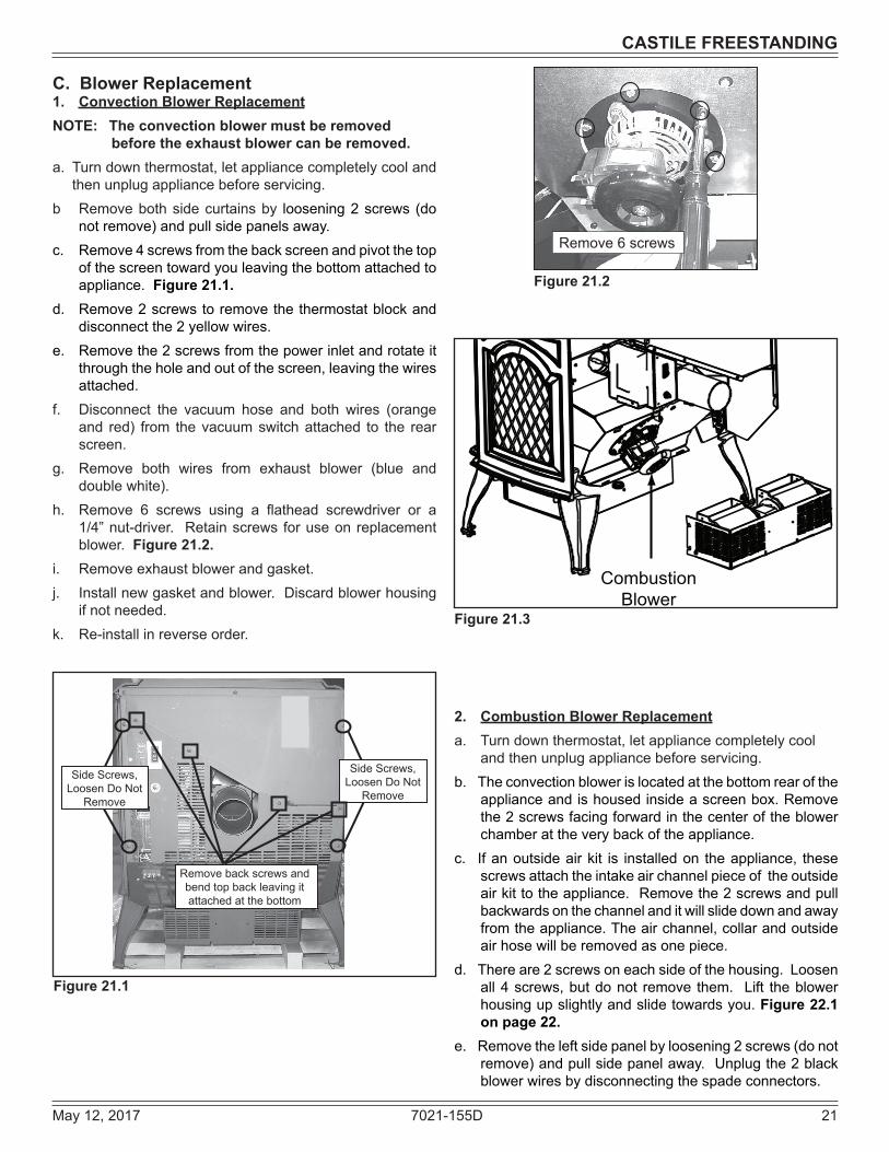
2. Combustion Blower Replacementa. Turndownthermostat,letappliancecompletelycool
andthenunplugappliancebeforeservicing.b. The convection blowerislocatedatthebottomrearofthe
appliance and is housed inside ascreenbox.Removethe 2screwsfacingforwardinthecenteroftheblowerchamberattheverybackoftheappliance.
c. Ifanoutsideairkit is installedon theappliance, thesescrewsattachtheintakeairchannelpieceoftheoutsideairkittotheappliance.Removethe2screwsandpullbackwardsonthechannelanditwillslidedownandawayfromtheappliance.Theairchannel,collarandoutsideairhosewillberemovedasonepiece.
d. Thereare2screwsoneachsideofthehousing.Loosenall4screws,butdonot remove them. Lift theblowerhousing up slightly and slide towards you. Figure 22.1 on page 22.
e. Removetheleftsidepanelbyloosening2screws(donotremove)andpullsidepanelaway.Unplugthe2blackblowerwiresbydisconnectingthespadeconnectors.
Figure 21.3
Combustion Blower
Remove 6 screws
C. Blower Replacement1. Convection Blower ReplacementNOTE: The convection blower must be removed
before the exhaust blower can be removed.a. Turndownthermostat,letappliancecompletelycooland
thenunplugappliancebeforeservicing.b Removebothsidecurtainsby loosening2screws (do
notremove)andpullsidepanelsaway.c. Remove4screwsfromthebackscreenandpivotthetop
ofthescreentowardyouleavingthebottomattachedtoappliance. Figure 21.1.
d. Remove2screwstoremovethethermostatblockanddisconnect the 2 yellow wires.
e. Removethe2screwsfromthepowerinletandrotateitthroughtheholeandoutofthescreen,leavingthewiresattached.
f. Disconnect the vacuum hose and both wires (orangeand red) from thevacuumswitchattached to the rearscreen.
g. Remove both wires from exhaust blower (blue anddoublewhite).
h. Remove 6 screws using a flathead screwdriver or a1/4”nut-driver. Retainscrewsforuseonreplacementblower.Figure 21.2.
i. Removeexhaustblowerandgasket.j. Installnewgasketandblower.Discardblowerhousing
ifnotneeded.k. Re-install in reverse order.
Figure 21.2
Figure 21.1
Side Screws, Loosen Do Not
Remove
Side Screws, Loosen Do Not
Remove
Remove back screws and bend top back leaving it attached at the bottom

22 7021-155D May 12, 2017
CASTILE FREESTANDING
Figure 22.1
f. To removeblower from thehousing, remove2 screwsinthefrontofthehousingandverycarefullybendthe2housingsidesoutandbendthebackofthehousingawayfromtheblower.Thisallowsforroomtoaccesstheback2screwsandnuts(4total)thatissecuringtheblowertothe housing.
g. Removeblowerandreplacewithnewblower.e. Re-install in reverse order.
Loosen (do not remove) 2 screws on each side and lift off blower housing
Remove left side panel and disconnect blower wires
Convection Blower & Housing
Figure 22.2
Figure 22.3
Figure 22.4
D. Baffle & Brick Set Removal1. Followpropershutdownprocedures.2. The top baffle has a hook on the bottom left side that
restsonthetoplipof thecastbrick. Thereisatabonthe bottom right side that hooks into the side bracket.Removethetopbafflebyfirstpullingthebaffleforwarduntilbackedgedropsdown.Thenslidebafflebackuntilthefrontedgeclearstheshelfthatithadbeenrestingon.Figure 22.2
3. The topbafflemustberemovedbeforeyoucanremovethe rightand leftbrick. Remove the rightbrickbyhold-ingtoplipofbrickandliftingup,thenpushoutsideedgeback.Slidebricktotherightuntilitisflushwiththefirebox.Rotate the insideedgeof thebrick forwardand removebrick.Repeatforleftbrick.Figure 22.3.
Remove Right& Left Brick
VacuumExhaust Area
Right BrickRemoved
May 12, 2017 7021-155D 23
CASTILE FREESTANDING
6 Reference Materials
2. Convection BlowerTheconvectionblowerismountedatthebottomrearoftheappliance.Thereare2impellers,oneoneachsideofthemotor.Theconvectionblowerpushesheatedairthroughtheheatexchangesystemintotheroom.3. Combustion BlowerThecombustionblowerislocatedontherightsideofapplianceandisdesignedtopulltheexhaustfromtheapplianceandpushitoutthroughtheventingsystem.4. Feed SystemThefeedsystemislocatedontherightsideoftheapplianceandcanberemovedasanentireassembly.Theassemblyincludesthefeedmotor,mountingbracket,bearingandfeedspring(auger).Thehollowfeedspring(auger)pullspelletsupthefeedtubefromthehopperareaanddropsthemdownthefeedchuteintothefirepot.5. Fire potThefirepot ismadeofhighqualityductile ironandhasacleaning pull-out rod. The floor of the fire pot opens forcleaningwhenyoupullouttherod.Besurethatthefloorreturnstoacompletelyclosedpositionoryourappliancewillnot operate properly.6. FuseThefuseislocatedonthefrontofthejunctionboxontherightsideofappliance.Thefusewillblowshouldashortoccurandshutoffpowertotheappliance.7. Heat ExchangersTheheatexchangerstransferhotairfromtheexhaustsystemintoconvectionair.Removethestainlesssteeltopbaffletoaccess the heat exchangers. There are 2 clean out rods located under the heat exchangers.
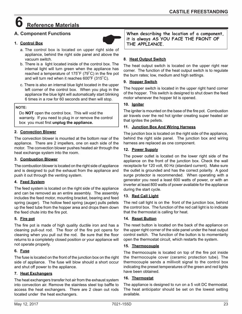
When describing the location of a component, it is always AS YOU FACE THE FRONT OF THE APPLIANCE.
A. Component Functions
1. Control Box a.The control box is located on upper right side of
appliance,behindtherightsidepanelandabovethevacuumswitch.
b.Thereisalightlocatedinsideofthecontrolbox.Theinternal light will turn green when the appliance has reachedatemperatureof175oF(79°C)inthefirepotand will turn red when it reaches 600oF(315°C).
c.Thereisalsoaninternalbluelightlocatedintheupperleftcornerof thecontrolbox. Whenyouplug in theappliancethebluelightwillautomaticallystartblinking6timesinarowfor60secondsandthenwillstop.
E
NOTE:Do NOTopenthecontrolbox.Thiswillvoidthewarranty.Ifyouneedtopluginorremovethecontrolboxyoumustfirst unplug the appliance.
8. Heat Output SwitchThe heat output switch is located on the upper right rear corner.Thefunctionoftheheatoutputswitchistoregulatetheburnrates;low,mediumandhighsettings.9. Hopper SwitchThe hopper switch is located in the upper right hand corner ofthehopper.Thisswitchisdesignedtoshutdownthefeedmotorwheneverthehopperlidisopened.10. IgniterTheigniterismountedonthebaseofthefirepot.Combustionair travels over the red hot igniter creating super heated air that ignites the pellets. 11. Junction Box And Wiring HarnessThejunctionboxislocatedontherightsideoftheappliance,behind the right side panel. The junction box andwiringharnessarereplacedasonecomponent.12. Power SupplyThepower outlet is locatedon the lower right sideof theapplianceon the frontof the junctionbox.Check thewallreceptaclefor120volt,60Hz(standardcurrent).Makesurethe outlet is grounded and has the correct polarity. A good surgeprotector is recommended. Whenoperatingwith ageneratoryouneedaleast600wattsofpower,orwithaninverteratleast800wattsofpoweravailablefortheapplianceduring the start cycle.13. Red Call LightTheredcalllightisonthefrontofthejunctionbox,behindthecontrolbox.Thefunctionoftheredcalllightistoindicatethatthethermostatiscallingforheat.14. Reset ButtonTheresetbuttonislocatedonthebackoftheapplianceontheupperrightcornerofthesidepanelundertheheatoutputcontrolswitch.Thefunctionofthebuttonistomomentarilyopenthethermostatcircuit,whichrestartsthesystem.15. ThermocoupleThe thermocouple is located on top of the fire pot insidethe thermocouple cover (ceramic protection tube). Thethermocouple sends amillivolt signal to the control boxindicatingthepresettemperaturesofthegreenandredlightshavebeenobtained.16. ThermostatTheapplianceisdesignedtorunona5voltDCthermostat.The heat anticipator should be set on the lowest settingavailable.

24 7021-155D May 12, 2017
CASTILE FREESTANDING
17. Snap Disc #1 (Convection Blower) 110°FSnapdisc#1islocatedontherightsideoftheapplianceonthetopoftheheatexchangerbox.Thereare2purplewiresconnectedtoit.Thissnapdiscturnstheconvectionbloweronandoffasneeded.Powerisalwayspresentatsnapdisc#1.18. Snap Disc #2 (Fuel Delivery Interrupt) 250°FSnapdisc#2isalsolocatedonthebacksideofthefeeddroptube.Thereare2orangewiresconnectedtoit.Thissnapdiscwillturnoffthefeedsystemwhichwillturnofftheapplianceif an over fire condition should occur or if the convectionblowershouldfailtooperate.Ifthisoccursthesnapdiscwillautomaticallyresetitself.19. Snap Disc #3 (Back Burn Protector) 250°FSnapdisc#3ismountedonthebackof theaugertubeinthecenteroftheapplianceandhasaredresetbutton.To
accessitremovetherightsidepanel.Ifthefiretriestoburnbackintothefeedsystemorpushexhaustupthefeedtube,thissnapdiscwillshuttheentiresystemoff.Thisdiscmustbemanuallyreset.20. Vacuum SwitchThevacuumswitchislocatedontherightsideoftheappliancebehindrightsidepanel.Thisswitchturnsthefeedsystemonwhenvacuumispresentinthefirebox.Thevacuumswitchisasafetydevicetoshutoffthefeedmotoriftheexhaustortheheatexchangersystemisdirtyorpluggedorifthefireboxdoor is open. 21. Wiring HarnessSee Figure 24.1 below.
Figure 24.1
VACUUMSWITCH
SNAPDISC #2
CAPACITOR FEEDMOTOR
SNAPDISC #1
CONVECTIONBLOWER
COMBUSTIONBLOWER
SNAPDISC #3
FUSE
RESETBUTTON
CALLLIGHT
THERMOS TATBLOCK
HEAT OUTPUTSWITCH
THERMOCOUPLE
IGNITOR
YELLOW
YELLOW
RED
RED
ORANGE
WHITEBLUE
BLUE
PURPLEGRAY
BLACK
BLACK
BLACK
BLACK
HOPPER SWITCH

May 12, 2017 7021-155D 25
CASTILE FREESTANDING
Figure 25.1
Figure 25.2
Figure 25.3
Convection Blower & HousingFeed Motor
HighMedLow
Heat Output Switch
Reset Button
ResetButton
Combustion Blower
TERMINAL BLOCKCENTER 2 SCREWS FOR
THERMOSTAT WIRES
POWER OUTLET
FUSE
Fuse
Red Call Light is located on top of Junction Box behind the Control Box.
Control Box
Vacuum Switch
Heat Exchanger Tubes
Cleaning Rods
B. Component Locations

26 7021-155D May 12, 2017
CASTILE FREESTANDING
Service PartsR
Castile-FS-BBeginning Manufacturing Date: Oct. 2009
Ending Manufacturing Date: Active
12
3
4
56
78
910
11
1213
1415
1617
18
19
20
21
22
23
24
30
25
262728
29
Castile Pellet Freestanding Stove
CASTILE-CSB-B, , CASTILE-MBK-B, CASTILE-PMH-B CASTILE-CWL-B (Oct 2009 thru June 2011)
Part number list on following pages.5/17
C. Exploded Drawings

May 12, 2017 7021-155D 27
CASTILE FREESTANDING
Service PartsR
Castile-FS-BBeginning Manufacturing Date: Oct. 2009
Ending Manufacturing Date: Active
IMPORTANT: THIS IS DATED INFORMATION. Parts must be ordered from a dealer or distributor. Hearth and Home Technologies does not sell directly to consumers. Provide model number and serial number when requesting service parts from your dealer or distributor.
Stocked at Depot
ITEM DESCRIPTION COMMENTS PART NUMBER
1 Hopper Lid Assembly
Black SRV7021-022MBK
Mahogany SRV7021-022PMH
Sienna Bronze SRV7021-022CSB
Willow SRV7021-022CWL
Bumper, Rubber Pkg of 12 SRV224-0340/12 YMagnet Round SRV7000-140 Y
2 Top
Black 7021-101MBKMahogany 7021-101PMHSienna Bronze 7021-101CSBWillow 7021-101CWL
3 Cast Retainer Upper SRV7021-1414 Convection Air Director SRV7021-1235 Hinge Bracket SRV7021-1156 Outer Skin Left SRV7021-1197 Brick, Left / Right, Cast 414-02708 Brick, Center, Cast 414-02609 Cast Retainer Lower Left Assembly SRV7021-018
10.1 Pull Rod Assembly SRV7021-005Knob, Ash Dump Control Rod 832-3020Spring, Firepot 200-2050
10.2 Wing Thumb Screw 8-32 x 1/2 Pkg of 24 7000-223/24 Y10.3 Heating Element Assembly 18” (Loop Igniter) Pkg of 10 SRV7000-462/10 Y10.4 Firepot Assembly SRV414-5200 Y
Bushing, Firepot 410-8320 YFloor, Firepot 414-0290 YGasket, Firepot SRV240-0930 YNut, Lock 1/4-20 Pkg of 25 226-0090/25 YBolt, Firepot, 1-1/4” Long Pkg of 25 225-0120/25 Y
10.5 Thermocouple Cover Pkg of 10 812-4920 Y10.6 Thermocouple 812-4470 Y10.7 Thermocouple Clamp SRV7001-203 Y
Additional service part numbers appear on following page.
10.1
10 210.3
10.710.4
10.610.5
#10 Firepot Assembly and Asscociated Parts
D. Service Parts

28 7021-155D May 12, 2017
CASTILE FREESTANDING
Service PartsR
Castile-FS-BBeginning Manufacturing Date: Oct. 2009
Ending Manufacturing Date: Active
IMPORTANT: THIS IS DATED INFORMATION. Parts must be ordered from a dealer or distributor. Hearth and Home Technologies does not sell directly to consumers. Provide model number and serial number when requesting service parts from your dealer or distributor.
Stocked at Depot
ITEM DESCRIPTION COMMENTS PART NUMBER11 Exhaust Conbustion Blower, 45 CFM 812-4400 Y
Gasket, Exhaust Combustion Blower (between…)...Housing & Stove SRV240-0812 Y...Motor & Housing 812-4710 Y
12 Ashcatcher - Must specify colorBlack 413-0010BKPorcelain Color 413-0010PORPowder Coat 413-0010PWD
13 FaceBlack 413-0030BKPorcelain Color 413-0030PORPowder Coat 413-0030PWD
14 Door Assembly SRV7021-00714.1 Hinge, Female SRV450-291014.2 Door Frame SRV7021-114
Gasket, Tadpole, 3/8 10 ft. 842-5130 Y14.3 Screw, Pan Head Philips, 10/32 x 1/4 Pkg of 24 229-1230/24 Y14.4 Screw, Machine Screw 1/4-20 x 5/8 Pkg of 24 220-0440/24 Y14.5 Door Latch Assembly 7021-00614.6 Glass Assembly (w/gasket) 17-1/4” W x 11-5/8” H SRV7001-038 Y14.7 Retainer, Rope SRV7001-192 Y
Tape, 1/2” X 1/16, 10 Ft 10 ft. 240-0290/10 YTape, Door Corner 1 ft. SRV7027-227 Y
15 Ash Drawer Front SRV7021-13816 Ash Drawer Gasket SRV7021-13917 Ash Drawer SRV7021-14018 Igniter Access Plate SRV413-038019 Convection Blower, 150 CFM 812-4900 Y20 Shroud, Convection Blower SRV413-030021 Cast Retainer Lower Right Assembly SRV7021-021
Additional service part numbers appear on following page.
#14 Door Assembly14.1
14.2
14.3
14.7
14.4 14.5
14.6

May 12, 2017 7021-155D 29
CASTILE FREESTANDING
Service PartsR
Castile-FS-BBeginning Manufacturing Date: Oct. 2009
Ending Manufacturing Date: Active
IMPORTANT: THIS IS DATED INFORMATION. Parts must be ordered from a dealer or distributor. Hearth and Home Technologies does not sell directly to consumers. Provide model number and serial number when requesting service parts from your dealer or distributor.
Stocked at Depot
ITEM DESCRIPTION COMMENTS PART NUMBER
22 Side
Black SRV7021-125MBK
Mahogany SRV7021-125PMH
Sienna Bronze SRV7021-125CSBWillow SRV7021-125CWL
23 Convection Plenum Back SRV7021-12024 Outer Skin Right SRV7021-11825 Vacuum Switch SRV7000-531 Y26 Control Board 3 Speed SRV7000-704 Y27 Wire Harness / Junction Box/ Heat Output Switch SRV7001-194 Y
Block, Thermostat Term Dv 230-069028 Outer Skin Back SRV7021-11729 Exhaust Transition Assembly SRV7021-003
30 Feed Assembly 812-4760 Y30.1 Screw 8-32 x 3/8 Pkg of 40 225-0500/40 Y30.2 Feed Motor 812-4421 Y30.3 Collar, Set, 7/8 229-052030.4 Bearing, Feed System, Nylon SRV7000-598 Y30.5 Gasket, Feed Motor SRV240-0731 Y30.6 Feed Spring Assembly (Only) SRV7001-046 Y30.7 Screw 5/16 - 18 x 1/4 Pkg of 25 225-0550/25 Y
Additional service part numbers appear on following page.
#30 Feed Assembly30.1 30.2 30.3 30.4
30.530.6
30.7

30 7021-155D May 12, 2017
CASTILE FREESTANDING
Service PartsR
Castile-FS-BBeginning Manufacturing Date: Oct. 2009
Ending Manufacturing Date: Active
IMPORTANT: THIS IS DATED INFORMATION. Parts must be ordered from a dealer or distributor. Hearth and Home Technologies does not sell directly to consumers. Provide model number and serial number when requesting service parts from your dealer or distributor.
Stocked at Depot
ITEM DESCRIPTION COMMENTS PART NUMBERAsh Drawer Assembly - w/Door, Gasket, Ashpan SRV7021-020Baf e Assembly 7001-034 YBracket, Snap Disc 7005-253
Component Pack Assembly Black SRV7021-011Mahogany SRV7021-017Sienna Bronze SRV7021-016
Cleanout Tool 414-1140 YHarness, Thermostat Wire 230-0810Leveling Assembly 7000-000
Paint Touch-Up, 4 OzMatte Black 812-0910Mahogany 855-1450Sienna Bronze TOUCHUP-CSB
Power Cord 812-1180 YDe ector, Bottom Airwash 413-0680Feed Adjustment Plate 7001-182Fuse, 7 Amp Pkg of 10 812-0380/10 YFuse, (for control Box) Pkg of 10 812-3780/10 YGasket, Hopper, Front/Back SRV7021-147Hinge, Door, Male SRV450-2810Hopper Lid Switch Assembly SRV7021-023 Y
Hopper Lid Magnetic Switch SRV7000-375 YHopper Top SRV7021-108Hose, Vacuum, 5/32 Id 3 Ft. SRV240-0450 YLog Set (Optional) LOGS-30-OE
Log, Left Rear 7050-144Log, Right Rear 7050-143
Magnet Bracket SRV7021-129Plate, Ash Cleanout 7001-186Reset Button Assembly SRV7000-040Scraper Repair Kit SCRAPER-CSTLSnap Disc Manual Reset SRV230-1290 YSnap Disc, 110-20 SRV230-1220 YSnap Disc # 2 On Droptube SRV7000-268 YWire Harness Hopper Switch SRV7050-130 YWire Harness Snap Disc SRV7001-224
Additional service part numbers appear on following page.

May 12, 2017 7021-155D 31
CASTILE FREESTANDING
Service PartsR
Castile-FS-BBeginning Manufacturing Date: Oct. 2009
Ending Manufacturing Date: Active
IMPORTANT: THIS IS DATED INFORMATION. Parts must be ordered from a dealer or distributor. Hearth and Home Technologies does not sell directly to consumers. Provide model number and serial number when requesting service parts from your dealer or distributor.
Stocked at Depot
ITEM DESCRIPTION COMMENTS PART NUMBEROPTIONAL ACCESSORIES
Collar, Offset, Top Vent 812-3570Damper, 3 Inch - Tall Vertical Installs Only PEL-DAMP3 YDamper, 4 Inch - Tall Vertical Installs Only PEL-DAMP4Outside Air Kit, Rear 811-0872
Channel, Air Intake SRV413-7040Cover, Outside Air Kit, Floor 411-1071Hose, Alum Flex, 2 Inch x 3 Ft 3 Ft SRV200-0860Outside Air Cap Assembly 7001-044Outside Air Collar Assembly SRV7001-045Trim Plate, Outside Air Kit 412-7100
Pullrod Handle PULLROD-HNDLSmart-Batt Il 841-0970Smart-Stat Il 841-0960Thermostat, Mechanical 812-3760 YThermostat, Programmable 811-0520Top Vent Adapter TPVNT-2Vent Adapter, 90, Cleanout TPVNT-6Vent Adapter, Rear 811-0620
FASTENERSAvk Rivnut Repair Kit - with 1/4-20 & 3/8-16 Rivnut Tools RIVNUT-REPAIR YBolt, Hex Head, 1/4-20 X 1 Pkg of 10 25221A/10 YHinge Pin (Rivet) Button Head Pkg of 25 25272/25 YNut, Capped, Push, 1/4 Pkg of 24 7000-157/24 YNut, Keps Lock, 8-32 Pkg of 40 226-0060/40 YNut, Ser Flange Small 1/4-20 Pkg of 24 226-0130/24 YNut, Wing, 8-32 Pkg of 24 226-0160/24 YRivet, Right Iron, 1/4 X 1-1/4 Pkg of 25 229-0090/25 YScrew, Flat Head Philips 8-32 X 1/2 Pkg of 10 832-0860 YScrew, Pan Head Philips 10-32 X 3/8 Pkg of 40 21799A/40 YScrew, Pan Head Philips 8-32 X 3/4 Pkg of 24 229-1100/24 YScrew, Sheet Metal #8 X 1/2 S-Grip Pkg of 40 12460/40 YThumbscrew, 1/4-20 X 3/4 Pkg of 10 844-5070

32 7021-155D May 12, 2017
CONTACT INFORMATION
Hearth & Home Technologies352 Mountain House Road
Halifax, PA 17032Division of HNI INDUSTRIES
Please contact your Quadra-Fire dealer with any questions or concerns. For the number of your nearest Quadra-Fire dealer
log onto www.quadrafire.com
DO NOT DISCARD THIS MANUALCAUTION
• Important operating and maintenance instruc-tions included.
• Leave this manual with party responsible for use and operation.
• Read, understand and follow these instruc-tions for safe installa-tion and operation.
DO NOTDISCARD
We recommend that you record the following pertinent information for your heating appliance.
Date purchased/installed:_________________________________________________________________________
Serial Number:____________________________________ Location on appliance:___________________________
Dealership purchased from:________________________________________ Dealer phone:_1(_____)_____-______
Notes:________________________________________________________________________________________
______________________________________________________________________________________________
______________________________________________________________________________________________
______________________________________________________________________________________________
This product may be covered by one or more of the following patents: (United States) 5341794, 5263471, 6688302, 7216645, 7047962 or other U.S. and foreign patents pending.