Installation & Operating manual - Hearth N...
34
3-90-08311R22_08/13 SAFETY NOTICE PLEASE READ THIS ENTIRE MANUAL BEFORE YOU INSTALL AND USE YOUR NEW ROOM HEATER. FAILURE TO FOLLOW INSTRUCTIONS MAY RESULT IN PROPERTY DAMAGE, BODILY INJURY, OR EVEN DEATH. SUITABLE FOR INSTALLATION IN MOBILE HOMES. IF THIS HARMAN STOVE IS NOT PROPERLY INSTALLED, A HOUSE FIRE MAY RESULT. FOR YOUR SAFETY, FOLLOW INSTALLATION DIRECTIONS. CONTACT LOCAL BUILDING OR FIRE OFFICIALS ABOUT RESTRICTIONS AND INSTALLATION INSPECTION REQUIREMENTS IN YOUR AREA. CONTACT YOUR LOCAL AUTHORITY (SUCH AS MUNICIPAL BUILDING DEPARTMENT, FIRE DEPARTMENT, FIRE PREVENTION BUREAU, ETC.) TO DETERMINE THE NEED FOR A PERMIT. DO NOT USE MAKESHIFT COMPONENTS OR OTHER COMPROMISES DURING INSTALLATION OR SERVICE. SAVE THESE INSTRUCTIONS. Installation & Operating Manual Model(s): DVC500 Coal Stoker NOTICE: SAVE THESE INSTRUCTIONS Hot glass will cause burns. • Do not touch glass until it is cooled • NEVER allow children to touch glass • Keep children away • CAREFULLY SUPERVISE children in same room as stove. • Alert children and adults to hazards of high temperatures. High temperatures may ignite clothing or other flammable materials. • Keep clothing, furniture, draperies and other flammable materials away. HOT SURFACES! Glass and other surfaces are hot during operation and cool down. WARNING !
Transcript of Installation & Operating manual - Hearth N...

3-90-08311R22_08/13
SAFETY NOTICEPlEASE rEAd ThIS ENTIrE mANuAl bEFOrE YOu INSTAll ANd uSE YOur NEw rOOm hEATEr. FAIlurE TO FOllOw INSTruCTIONS mAY rESulT IN PrOPErTY dAmAgE, bOdIlY INjurY, Or EvEN dEATh.SuITAblE FOr INSTAllATION IN mObIlE hOmES.IF ThIS hArmAN STOvE IS NOT PrOPErlY INSTAllEd, A hOuSE FIrE mAY rESulT. FOr YOur SAFETY, FOllOw INSTAllATION dIrECTIONS. CONTACT lOCAl buIldINg Or FIrE OFFICIAlS AbOuT rESTrICTIONS ANd INSTAllATION INSPECTION rEQuIrEmENTS IN YOur ArEA.CONTACT YOur lOCAl AuThOrITY (SuCh AS muNICIPAl buIldINg dEPArTmENT, FIrE dEPArTmENT, FIrE PrEvENTION burEAu, ETC.) TO dETErmINE ThE NEEd FOr A PErmIT.dO NOT uSE mAkEShIFT COmPONENTS Or OThEr COmPrOmISES durINg INSTAllATION Or SErvICE.
SAvE ThESE INSTruCTIONS.
Installation & Operating manual
model(s):DVC500 Coal Stoker
NOTICE: SAVE THESE INSTRUCTIONS
hot glass will cause burns.• Donottouchglassuntilitiscooled• NEVERallowchildrentotouchglass• Keepchildrenaway• CAREFULLYSUPERVISEchildreninsameroomas
stove.• Alertchildrenandadultstohazardsofhightemperatures. high temperatures may ignite clothing or other
flammable materials.• Keepclothing,furniture,draperiesandotherflammable
materialsaway.
hOT SurFACES!
Glassandothersurfacesarehotduringoperationandcooldown.
WARNING!

Thisapplianceisalsoapprovedforinstallationintoashop.
4”PelletVent
HarmanVentingComponentsOnly
5.5” X 7.5” adhesive backed metal label.
LISTED SOLID FUEL BURNING ROOMHEATER - MODEL: “DVC 500”
BARCODE LABEL008Serial No.No de série:
TESTED TO: ASTM E1509, and parts of UL127TEST DATE: July, 1996APPROVED FOR USE IN MANUFACTURED HOMES.
PrEvENT hOuSE FIrES:KEEPALLDOORSANDHOPPERLIDCLOSEDDURINGOPERATION.INSTALLANDUSEONLYINACCORDANCEWITHMANUFACTURE’SINSTALLATIONANDOPERATINGINSTRUCTIONS.CONTACTOLOCALBUILDINGORFIREOFFICIALSABOUTRESTRICTIONS&INSTALLATIONINSPECTIONREQUIREMENTSINYOURAREA.SEETHEINSTALLATIONMANUALANDCHECKWITHYOURLOCALCODESFORSPECIALINSTRUCTIONSWHENPASINGTHEVENTTHROUGHACOMBUSTIBLEWALLORCEILING.UNITMUSTBEPLACEDONANON-COMBUSTIBLEFLOORORFLOORPROTECTOREXTENDING16”TOTHEFRONT,8”TOTHESIDESAND3”TOTHEREAR.MINIMUM24GAUGESHEETMETAL.dIrECT-vENT-USEONLYHARMANDVC-VENTINGCOMPONENTSFROMTHEAPPLIANCEGTHROUGHTTHEOUTSIDEWALL.USEONLY4”TYPELORPLPELLETVENTONTHEOUTSIDEOFTHEHOME.dO NOT CONNECT TO A ChImNEY. dO NOT CONNECT ThIS uNIT TO A ChImNEY Or FluE SErvINg ANOThEr APPlIANCE.FuEl:ANTHRACITERICECOALONLY.THEEPAPROHIBITSTHEUSEOFANYOTHERFUEL,EXCEPTFORCOALIGNITION.INPuT rATINg:6LBS/HRElECTrICAl rATINg:2.5AMPS,120VOLTS,60HZREPLACEGLASSWITH5MMCERAMICONLYINSPECT ANd ClEAN vENTINg EXhAuST vENTINg SYSTEm rEQuENTlY.
mINImum ClEArANCES TO COmbuSTIblES:
UnittoSideWall 18”/457mm
UnittoRearWall 3”/76mm
StoveToptoCeiling 24”/610mm
CornerInstallation 9”/229mm
FlOOr PrOTECTION:
Front 16”/406mm
Sides 8”/203mm
Rear 3”/76mm
date of manufacture:
Manufactured by: Harman Home Heating - 352 Mountain House Road, Halifax PA 17032
2012 2013 2014 jAN FEb mAr APr mAY juN jul Aug SEP OCT NOv dEC
#3-90-08210rev bP.N. 3-90-08210
Please copy your serial numberfromthelabelonyourstovetotheboxbelow.
SErIAl NumbEr
SAmPlE lAbEl

33-90-08311R22_08/13
Index
Warnings 4
Introduction 5
Assembly 6
Installation 7
DirectVentPipe 14
DVC500MicroprocessorControl 15
Operation 17
Maintenance 19
Fuel 23
WiringDiagram 25
ControlandSafetySensors 26
Specifications 27
Troubleshooting 28
Warranty 30
Pleasereadthisentiremanualbeforeyouinstallanduseyournewroomheater.Failuretofollowinstructionsmayresultinpropertydamage,bodilyinjury,orevendeath.
SuITAblE FOr mObIlE hOmE INSTAllATIONS.
SAVETHESEINSTRUCTIONS
harman home heating352MountainHouseRoad
Halifax,PA17032www.harmanstoves.com
= Contains updated information

43-90-08311R22_08/13
Freshly delivered coal is watered down toeliminatedustwhenloadingandunloading.Wetricecoaldoesnotflowaswellasdampordrycoal.Wedonotrecommendburningwetcoal;however,werealizeifit'stheonlycoalyouhave,itisbettertoburnitthanbecold.Ifyoumustburnwetcoal,thefeedratemustbeincreasedinordertogetthesamesizefire.Asthewetcoalinthehopperdriesout,thefeedratemustbedecreased.Loadingwetcoalonceortwiceayearwillnotdamageyourstoveaslongasitishotandburning.Thedamageiscausedwhenthehopperhaswetcoalinitwhenthestoveiscold.Thiswillcauserustandcorrosionanditistotallytheoperator’sfault.Usuallyafterthecoaldriesforthreeorfourdays,dependingonconditions,itwillflowverywellandfeedproperly.Feedratewillbethesameaswithdrycoal.
wet Coal
(Never sleep in the same room with any coal burning stove.)
Carbon monoxide (CO) Awareness
Always empty the hopper when not burning for more than a week. when left standing for long periods with wet coal, the pusher block will rust and corrode, causing it to seize. If the stoker is then turned "on", damage to the pusher assembly and feed motor could result. This will be considered neglect and will void the warranty on those parts. Always check to see that moving parts are free before using, if the unit has not been burned for a period of time. This can best be determined by watching the cam block and pusher arm inside the right rear side door.
Always Empty hopper
Never use gasoline, gasoline-type lantern fuel, kerosene, charcoal lighter fluid, or similar liquids to start or “freshen up” a fire in this heater. Keep all such liquids well away from the heater while it is in use.
Carbonmonoxide,referredtoasCO,isacolorless,odorlessgasthatisproducedduringcombustionofcoalandotherfuels.CO fumes are toxic and can be fatal.TheDVC500 isa closed loopsystemspeciallydesignedtopreventtheescapeofCOandothercombustionproductsfromthestove.Eventhoughthisstoveisdesignedtobeassafeaspossible,it isimportantthatyouinstall a CO detector.Thisistrueforoil,gas,orwoodburningproductsaswell.
COdetectorsareverysensitiveandmaysoundanalarmforfumesotherthanCOorCOfromsourcesother than the stove such as car or lawnmowerexhaust.Ifthealarmsounds1.Increaseventilationbyopeningwindowsordoors.2.Make sure the stovedoorsandhopper lid are
closedandlatched.3.Check stove for electrical power and normal
operation.4.Checkforfalsealarm.
warnings

53-90-08311R22_08/13
ThisremarkabledesignbyHarmanfeaturestheVerti-flowDirectVentStokerSystem.This unique, high efficiency unit uses only outside air forcombustion.Micro-processorcontrolsprovideforanautomaticwiderangeofheatoutputfrom7,000to75,000BTU.Withabig93poundhoppercapacity,thisunitcanburnonhighapproximately16hoursorextendforover96hoursonlow.A Room Sensor connected to the micro-processorautomaticallyadjuststhefeedratetocompensateforchangesintemperature.Theashpanislargeenoughtoholdtheashfromonehopperfullofcoalatanysetting.The dvC 500 is the most advanced coal stove ever put into production. however, there are places where it should not be installed. If the end of the flue pipe is:1. less than 8 feet from an air intake.2. On the side of the house where a window is left open
for sleeping.3. less than 5 feet from a door.4. less than 7 feet above and 3 feet away from a public
walkway.5. less than 3 feet above ground level.6. between two buildings less than 10 feet apart.It is recommended that the end of the flue pipe terminates at least 12 inches away from the side of the building in order to minimize any fly ash build-up.
mobile home installations should be done in accordance with the manufactured home and Safety Standard (hud), CFr 3280, Part 24.
dAmP COAl ShOuld NOT bE lEFT IN ThE hOPPEr OF A COld STOvE.
Introduction

63-90-08311R22_08/13
1.Installthehopperlatchasshownatleft.2.Install3firebricksonthecastironanglebehindthe
grateasshown.3.Cementingratesasshownbelow.Thismayalreadybe
doneatthefactory.
3 Bricks
Grate Inserts
Fig.3
Assembly

73-90-08311R22_08/13
viewing glassTheglassinyourHarmanstoveisaspecialceramicglass.• Donotabusetheglassbystrikingorslammingthedoor.• Neverburntheapplianceifthedoorglassiscrackedorbroken.• ReplaceonlywithHarmansuppliedglass.Sootand/orfly-ashmayaccumulateontheviewingglass,andwillocassionallyneedtobecleaned.Cleantheglasswithasoftclothandmildglasscleaner.Donotspraycleaneronhotglass,andavoidtheuseofabrasivecleaners.GlassreplacementCarefullyremoveallremainingglassandgasketmaterialspriortoreplacingtheglass.Laythedoorfacedownonaflatsurface.Removetheglassretainersandscrews.Applythegasketmaterialtothefaceofthenewglass.Laytheglassintothedoor,makingsurethattheglassiscontainedwithinthechannelsandraisedareasofthedooritself.Laytheglassretainersintopositionandinstallthescrews.Tighteneachscrewevenlytoavoidmakinganystresspoints.
4 GLASS RETAINER CLIPS
4 GLASS RETAINER BOLTS
GLASS
GLASS GASKET
DOORHINGE PINS
PAW BOLT
BRASS HANDLE
HANDLE BOLT
WOOD HANDLE
SET SCREW

83-90-08311R22_08/13
Tips On InstallationBefore the positioning of the unit can be decided a fewquestionsshouldbeconsidered?1.Cantheunitbeventedproperlyandinstalledsafely?2.Willexhaustbeventedwherefumescanbuilduporbe
drawnintolowerlevelsofthestructure3.Willfumesandflyashaffecttheexteriorofthestructure
orsurroundingstructures?4.Are there any local regulations governing theuseand
placementoftheunit?5.Arethereanystructuralreasonswhytheunitcannotbe
placedwhereyouwant?6.Howcloseistheelectricaloutlet?Follow the guidelines to the left regarding clearances to combustible materials.Floor ProtectorThis stove should be placed on a non-combustible floorprotectorextending16inchestothefront,8inchestothesides,and1inchtotherear.Straight Through wall1.When positioning of the unit has been decided, use
measurementsonPage10forcuttingtheholethroughthewall.Don’tforgettofigurethethicknessofthefloorprotectorused.
2.Cutatleasta9"x9"holethroughthewall.3.Remove thesidedoors / rearcoverassembly (6black
screws,5/16"socketorstraightscrewdriver)4.Placetheunit in frontof theholeapproximately 1/2"
closertothewallthanthelengthofthewalltermination.(Fromoutsideofwalltobackofunitwhereterminationboltsup)
5.Takethewallterminationoutsideandslideitintotheholeuntilitmatestotherearoftheunit.Goinsideandinstalltheboltsandtighten,makingsurethegasketisinplaceandthefluepipesectionislevel.
6.Repositiontheunitinwarduntilthestainlesssteelintakesectioncomesagainsttheoutsidewallsurface.NOTE:If thewall is over 8" thick youwill needa longerwalltermination.Thestandardterminationwillprovide3"ofwallclearancebehindthestove,witha8"wall.Therefore,witha5"thickwall,itwillprovide6"ofclearancebehindthestove.
7.Checktheexterioroftheterminationforbestfitandscrewtoexteriorandcaulkwithhighgradeexteriorcaulking.
Installation
dO NOT INSTAll A FluE dAmPEr IN ThE EXhAuST vENTINg SYSTEm OF ThIS uNIT
dO NOT CONNECT ThIS uNIT TO A ChImNEY FluE SErvINg ANOThEr APPlIANCE.
INSTAll vENT AT ClEArANCES SPECIFIEd bY ThE mANuFACTurEr
ROUGH OPENING
Fig.6
Fig.7
Alternate floor protector dimension may be used as long as they satisfy the measurement requirements shown above.Minumum size floor protection for a corner installation hearth pad is 54" x 54" (USA ONLY).

93-90-08311R22_08/13
Installation
WallTrimPlate
WallTrimPlate
Gasket
WallTermiation
Standard wall Termination
Fig.9
Open
Fig.8
8.Completeanyotherexteriorfluepipingnecessary,using4"pelletventing.
9.Backinside,placethe2halvesoftheinteriorwalltrimplateoverfluepipe.Usingtheblackpoprivets,fastentogether,thenslideitagainstthewallandfastenittothewall.
10.Replacethesidedoor/rearcoverassemblywith6blackscrews.
11.Completetheunitassemblyandtest.
WARNING!dO NOT INSTAll IN mObIlE hOmE SlEEPINg rOOm
CAUTION!ThE STruCTurAl INTEgrITY OF ThE mObIlE hOmE FlOOr, wAll, ANd CEIlINg/rOOF muST bE mAINTAINEd.

103-90-08311R22_08/13
Installation

113-90-08311R22_08/13
basement InstallationToinstallaDVC500inabasementyouwillneedadditionalDVCventsections.Thesesectionsaremadewitha316-gradestainlesssteellineranda20gaugegalvaneeledoutershell.Each joint is sealedwith a gasket and is bolted togetherwith4bolts.Inordertomaintainthebestseal,therearenoadjustablesections.Therearestraight,45degree,andTeefittings.RefertoPage14forallofthesectionsavailable.
WallTermination
Teewithcoverplate
StraightsectionsJointcovers
Teewithcoverplate
Fig.10
Fig.11
D
Never use venting other than harman dvC venting inside the building. It is the only vent certified for this appliance.
Refer topage12&14 tocalculatewhichsectionswillbeneededforyourinstallation.Corner InstallationAcornerinstallationrequiresa45degreesectioninadditiontothestandardwalltermination.Inordertocutaholeinthewallthatwillallowthestovetobeplacedanequaldistancetoeachwall,refertoPage13.
Installation

123-90-08311R22_08/13
Installation

133-90-08311R22_08/13
Installation

143-90-08311R22_08/13
ExteriorTerminationforwallthicknessupto8inches
1-10-08310
ExteriorTerminationforwallthicknessupto16inches
ExteriorTerminationforwallthicknessupto12inches
3-44-06256 1-10-083131-10-08314
1-10-08321
1-10-083171-10-08315
1-10-08316
1-10-08320
1-10-08319
1-10-083181-10-083221-10-083231-10-08324
1-10-08326
1-10-083111-10-08312
Gasket
Spacer3/16"
1-10-08325
12"45° "T"
6"9" 13"
8"12"
11"
10"
16"
27"
20"
37"
47"
9-5/8"8-3/4"
JointCover
harman direct vent Coal Flue Pipe venting System 1" Clearance to Combustibles
MaximumHorizontalRunis48Inches-(4ft.)
vent Pipe

153-90-08311R22_08/13
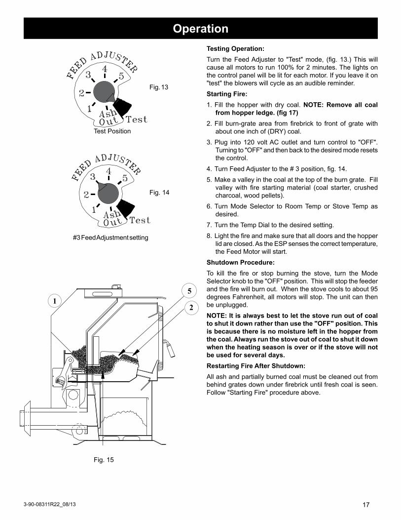
Feed AdjusterSets the maximum feed rate, 1 to 5
TestRuns all motors at full speed for two minutes to check operation. After two minutes the feeder stops and the distribution blower alternates from high to low every four seconds to remind you that you are still in "Test Mode".
Dist r ibut ion Blower speed adjustment range.
Temp DialAllows you to adjust the room temperature in Room Temp Mode using the outer scale marked in degrees Fahrenheit. It also allows you to adjust the stove temperature while in Stove Temp Mode using the inner scale marked from 1 to 7.
Mode Selector Allows you to choose between Room Temp Mode, Stove Temp Mode, or OFF. Also allows you to vary the Distribution Blower speed by turning the knob to the "high" or "low" side of each mode.
Power LightIndicates power is "on" to the control.
Indicates power to Distribution Blower
Indicates power to the Feed Motor.
Indicates power to Combustion Blower
Status LightWill be lit in either Stove or Room Temp Mode when pointer is not within "off" position band except after normal shut down. Blinks to indicate errors listed below.
Ash Removal positionSee page 19
ESP Control
Indicates power to the Draft Motor.
2 blinks:Indicatesthatthereisinsufficientnegativepressureinthefirebox.Thisbeginsashut-downprocessdescribedinmoredetailonPage31.Themostcommoncauseofthe2blinkstatusisleavingtheashdooropenwithoutturningtheFeedAdjusterto"AshOut".Forothercausesofa2blinkstatusseePage32.ThisrequiresaManualReset*.3 blinks:IndicatesthattheESP(ExhaustSensingProbe)hasgoneoutofrangeaspecifiednumberoftimes.Ifthestoveseemstobeperformingnormally,performaManualReset*.
4 blinks:CanoccuronlyinRoomTempModeandindicatesRoom Sensing Probe has failed or is not installed. If aRoomSensingProbeistheninstalled,thestatuslightwillautomaticallyreset.5 blinks: Indicatesa lackofcommunicationbetween thecircuitboardandtheTCP(TemperatureControlProbe).Thisrequiresamanualreset*.* manual reset:Disconnectpowercordforafewsecondsandreconnect.IferrorstilloccurscallyourDealer.
Status light Error messages
Fig.12
DDM Port Allows service technician to attach diagnostic meter when troubleshooting or verifying proper operation.

16 3-90-08311R22_08/13
ESPControl
HopperLidLatch
AshDoorLatchHandle
GlassDoorLatchHandle
SidePanelLatch
173-90-08311R22_08/13
Testing Operation:Turn theFeedAdjuster to "Test"mode, (fig.13.)Thiswillcauseallmotorstorun100%for2minutes.Thelightsonthecontrolpanelwillbelitforeachmotor.Ifyouleaveiton"test"theblowerswillcycleasanaudiblereminder.Starting Fire:1.Fill thehopperwithdry coal.NOTE: remove all coal
from hopper ledge. (fig 17)2.Fill burn-gratearea fromfirebrick to front of gratewith
aboutoneinchof(DRY)coal.3.Plug into120voltACoutletand turncontrol to "OFF".
Turningto"OFF"andthenbacktothedesiredmoderesetsthecontrol.
4.TurnFeedAdjustertothe#3position,fig.14.5.Makeavalleyinthecoalatthetopoftheburngrate.Fill
valleywith fire startingmaterial (coal starter, crushedcharcoal,woodpellets).
6.TurnModeSelector toRoomTemporStoveTempasdesired.
7.TurntheTempDialtothedesiredsetting.8.Lightthefireandmakesurethatalldoorsandthehopper
lidareclosed.AstheESPsensesthecorrecttemperature,theFeedMotorwillstart.
Shutdown Procedure:To kill the fire or stop burning the stove, turn the ModeSelectorknobtothe"OFF"position.Thiswillstopthefeederandthefirewillburnout.Whenthestovecoolstoabout95degreesFahrenheit,allmotorswillstop.Theunitcanthenbeunplugged.NOTE: It is always best to let the stove run out of coal to shut it down rather than use the "OFF" position. This is because there is no moisture left in the hopper from the coal. Always run the stove out of coal to shut it down when the heating season is over or if the stove will not be used for several days.restarting Fire After Shutdown:Allashandpartiallyburnedcoalmustbecleanedoutfrombehindgratesdownunderfirebrickuntilfreshcoalisseen.Follow"StartingFire"procedureabove.
Fig.15
12
5
#3FeedAdjustmentsetting
TestPosition
Fig.13
Fig.14
Operation

183-90-08311R22_08/13
ThissettingwillproducemediumheatwiththeDistributionBloweron"low".
Fig.16
when to use "Stove Temp mode"In "StoveTempMode" thecontrolwill regulate thefire tomatchaconstantexhausttemperature,basedonthe#1thru7settingsontheinnerportionofthetempdial.Heatoutputandfuelconsumptionwillremainconstant.Thismakesitpossibletotellhowlongahopperfullofcoalwilllast.Thedistributionblowerspeedcanbevariedaccordingtothepositionofthemodeselector,between"low"and"high",Fig.16.when to use "room Temp mode"In"RoomTempMode"heatoutputiscontrolledautomaticallybyuseoftheRoomSensingProbe.WhentheRoomSensingProbecallsforheat,thestovewillincreaseoutput.WhentheRoomSensingProbeisgettingclosetothesettemperature,thestovewillbegintoleveloffoutputandkeepthefireburningatjusttherighttemperaturetomaintainthatsetting.Ifthetemperatureintheroomexceedsthesetpoint,thestovewillidleonalowburnuntilmoreheatisneeded.HighoutputisdeterminedbytheFeedRate.ThemaximumFeedRateshouldbesetfor11/2"to2"ofashinfrontofthefire.In "RoomTempMode" fuel consumption is sacrificed forexactroomtemperature.Therefore,asitgetscolder,morecoalwillbeburnedautomatically.Thedistributionblowerspeedcanbevariedaccordingtothepositionofthemodeselector.
Keepcoaloffledges
Fig17
Thissettingwillproducearoomtemperatureof70degreeswiththeDistributionBlowerat"medium"speed.
ThissettingwillproducecontinuousmaximumheatoutputwiththeDistributionBloweratfullspeed.
Operation

193-90-08311R22_08/13
Ash Out PositionFig.18
MakenoteofthepositionoftheFeedAdjusterknobsoitcanbereturnedtothesamepositionwhenyouarefinishedremovingtheashes.Turn theFeedAdjusterknob to"AshOut", this is theashremovalsetting,Fig18.ThissettingturnsofftheCombustionBlowerandFeederMotorbutdoesnotturnoffDraftMotor.Nowtheashdoorcanbeopenedwithminimalexhaustleakage.Ifashremovaltakesmorethan4minutes,theDistributionBlowerwillstarttocycleupanddowntoindicatetheFeedAdjusterknobwasleftinthe"AshOut"position.ThisisnotaproblemifyouremembertoreturntheFeedAdjustertoitsprevioussettingwhencompleted.If left in the "Ash Out" position, the fire will burn out.
If the feed adjuster is left in the "Ash Out" position the fire will burn out.
daily maintenanceAsh removalWitheachhopperofcoalthatisburned,approximatelyoneashpanfullofashesmustberemoved.(Fig.19)Itmaytakefromonetofourdaysfortheashpantogetfull,dependingontheburnrate.Failure to remove the ashes will result in a blocked grate and the fire will not burn properly.Remember,theashpanwillbehot,soalwayswearprotectivegloves.Ash removal Setting:The"AshOut"positiononthefeedadjusterknobisforashremoval(Fig.18).ThispositionstopstheCombustionBlower,theFeederMotor,andslowstheDistributionBlowersothedoorscanbeopened.Thisistolimitexhaustfumesfromleavingtheunit.don't forget to turn knob back to previous feed number setting after completion of ash removal.
Ashes should be placed in a metal container with a tight fitting lid. The closed container of ashes should be placed on a noncombustible floor or on the ground, well away from all combustible materials, pending final disposal. If ashes are disposed of by burial in soil or otherwise locally dispersed, they should be retained in the closed container until all cinders have thoroughly cooled.
Fig.19
removing Ash while unit Is burning:WARNING!
OPENINg ThE vIEwINg dOOr Or ASh dOOr wITh-OuT TurNINg ThE FEEd AdjuSTEr TO ThE "ASh OuT" POSITION mAY CAuSE COmbuSTION gASES ANd FlY ASh TO ESCAPE.
CAUTION!ASh PAN hANdlE wIll bE hOT, wEAr glOvES.

203-90-08311R22_08/13
weekly maintenanceEmpty Fines TrayThe small FinesTray in the side of the stoker should beremovedandemptiedToremovetheFinesTray,firstopenthedoorontheleftrearof the stove. Next, loosen the thumb screws holding theFinesTrayCover,fig#20.Next,turnthecover90degreesandslideouttheTrayasshown.IftheTrayhasover-flowed,useavacuumcleanertoreachintotheopeningandremovetheexcessmaterial.Cleaning glass while unit Is burning:Caution:The glass and door frame will be hot, gloves must be worn.Turnthetemperaturecontroltolowestsettingandallowthestove tocooldown.Haveallcleaningsupplies readyandcloseby.Takenoteatwhich#theFeedAdjusterisset,Fig14.TurnFeedAdjusterknobto"AshOut".(Thisistheashremoval setting.) This setting turns "off" theCombustionBlowerandFeederMotorbutdoesnotturn"off"theDraftMotor.Nowtheviewingdoorcanbeopenedwithminimalexhaustleakage.Useasafetyrazorinhandleandscrapetheinsideoftheglasswiththebladealmostflattothesurface,Fig21.Iffurthercleaningisnecessary,thewindowcannowbecleanedwithliquidcleanerandanonsyntheticcloth.CAuTION:do not spray cleaner directly on hot glass.Ifthecleaningtakesmorethan4minutes,theDistributionBlowerwillstarttocycleupanddowntoindicatetheFeedAdjusterknobwasleftinthe"AshOut"(ashremovalsetting).Thisisnotaproblem,justremembertoreturntheFeedAdjustertoitsprevioussettingwhencompleted.
FINES TRAY COVER
FINES TRAY
Fig20
Fig21
Soot and Fly AshTheproductsofcombustionwillcontainsmallparticlesofflyash.Theflyashwillcollectintheexhaustventingsystemandrestricttheflowofthefluegases.Incompletecombustion,suchasoccursduringstartup,shutdown,orincorrectoperationoftheroomheater,willleadtosomesootformationwhichwillcollectintheexhaustventingsystem.Theexhaustventingsystem should be inspected at least once every year todetermineifcleaningisnecessary.

213-90-08311R22_08/13
A 3-month cleaning will give you a base line as to how often your dvC500 needs to be cleaned. Cleaning intervals will differ in each installation because of the ash and moisture content of the coal and the amount of coal burned. NOTE: unit should be off & cooled down enough to perform these maintenance items:1.RemoveAshPanthenremoveashshieldbehindAshPan,
fig.22.Lifttheshieldupandforwardinordertoremoveitfromthestove.ThiswillexposetheBlowerCoverandLatch,fig.23.
2.RotatetheLatchcounterclockwisetotheverticalpositionasshowninfig.24.
3.RemovetheBlowerCoverbytiltingtheleftsideslightlyforward.Next, slide theCover left and out of the slotthatholdstherightsideinplace.TheCovercannowberemovedtoexposetheDraftBlowerWheelandExhaustOutlet,fig.25.
4.Theblowerwheel,blowerhousing,andexhaustoutletcannowbecleanedwithabrushandvacuumcleaner.NOTE:TheESPprobeislocatedattherearoftheexhaustoutletshowninfig28.be careful not to damage the probe when cleaning.
5.OpentheFinesCoveronthebottomofthefeederunderthegratesandclean,seefig.26. ATTENTION: mAkE SurE COvEr IS ClOSEd ANd TIghTENEd bEFOrE rElIghTINg uNIT. uNIT wIll NOT OPErATE PrOPErlY wITh ClEAN OuT COvEr lEAkAgE.
6.Checkthefluepipeforexcessbuildupofflyashandcleanifnecessary.
7.Cleantheglassthoroughly,useasafetyrazortoscrapethesulfurbuildupfromthesurfaceofglass.Thencleanwithstandardwindowcleaningfluid,Fig.21.
8.Inspect all gaskets for damageand turn the control to"test",formotortestbeforerelightingafire.
Fig23Latch Blower Cover
maintenance Every 3 months:
Fig24Rotate Latch
Fig22
Never Block Air Outlets on top of stove, above door.
Ash Shield
Tabs

223-90-08311R22_08/13
The End Of Season Shut down list.1.Allowthestovetorunoutofcoalinordertoextinguishthe
fire.Thissaveshavingtoremovethecoalfromthehoppermanuallyandmostimportantly,drivesthemoistureoutofthestovethatmaybepresentinthecoal.
2.Performallthestepsofthe3monthmaintenancelist.3.Cleantheglassasshowninfig.21.4.Empty the fines trayand inspect thearea for rust and
corrosion5.Makesurethehopperisempty.Wetordampcoalinthe
hopperwillpromoterust.6.RemovetheFSSTubefromtherearofthefirebox(fig.27)
andcleanthebrassfittinggoingintothefireboxwithapipecleaner.Reconnecttube.
7.TheFSS line filter canbe changedannually to insureproperflow,however,itmayonlybenecessaryifthefilterisdiscolored.
8.Remember to cover the flue pipe over the summer toblockoutrodentsandbirds.Placeanoteinsidetheunittoremindyourselforothersnottoforgettouncoverthefluepipebeforelightingafire.
Prevent rustSummertimemoistureandhighhumidityareyour stove'senemy. A clean stovewill have less flyashand fines toabsorbmoistureandcauserustandcorrosion.Allowingwetcoaltoremaininthehopperofacoldstovewillpromotetheformation of rust and corrosion. Some owners choose tosprayalightcoatingofoilonallinternalworkingsandthefireboxasarustinhibitor.Annual ServiceItisrecommendedthatyourDVC500isservicedannuallybyyourtrainedHarmandealer.Thebesttimeforthisserviceisduringanon-useperiod.Youmaychoosetocombinethisservicewiththeendofseasonmaintenance.
End of heating Season maintenance:
Exhaust Outlet
Blower Wheel
Blower CoverFig.25
Grate Clean-Out CoverFig.26
Fig.27
FSS Tube
FSS Line Filter

233-90-08311R22_08/13
motors
FuelTheDVC500isdesignedtoburnAnthracite rice Coal,whichisapproximately3/8"longandwideby3/16thick.AnthracitecoalisconsideredeitherWhiteAshorRedAsh.WhiteAshCoalwillhave13to14,000btu'sperlb.Whiteashcoalusuallyhaslessashandwillburnlonger.RedAshcoalisusuallyabout12,000btu'sperlb.andishigherinvolatiles.Highervolatilesmakesthecoaleasiertolightandproducesamoreyellowflame.AtaverylowburnratetheTCP(TemperatureControlProbe)maybeactivatedwithRedAshcoal,especiallyifthehopperlidisopenorleaking.TheTCPsensesthetemperatureofthefeederandfeedscoalifthetemperaturerisestoomuch.Thispreventsthefirefromreachingthecoal in the hopper. RedAsh Coal may form klinkers(fusedtogetherash)whichmaycausegrateblockageinseverecases.
AnthraciteCoal canbepurchased inbagsor inbulk.Ifyoubuyinbulk,trytohavethecoaldeliveredbeforetemperaturesreachthefreezinglevel.Thisisbecausesaltmaybeaddedtothecoaltokeepitfromfreezingonthetruck.Thiswillnotaffectburningbutwillpromoterustandcorrosion.SomeCoalCompanieswashtheircoalbetterthanotherstoremovefinesanddirt.Thismakesairflowthroughthecoalbetterandproduceslessflyash.Whetherbaggedorinbulk,thecoalmustbedrybeforeloadingitintothestove.Ataminimum,openbagsafewdaysinadvancetoallowdrying.Buyyourbulkcoalmidsummertoallowplentyoftimefordrying.Good, clean, White Ash Coal is the fuel of choice,"however"RedAshCoalwillalsoburnwell.AslongasitisAnthracite.
DistributionBlower
3-21-22647
DraftMotor3-21-08639
FeedMotor3-20-60906
ESPProbe3-20-00744
Fig.28
CombustionBlower
1-10-08332

243-90-08311R22_08/13
TheDVC500gratesystemiscomposedoffourpieces:thegrateholder,(2)-63holegrateinserts,andgrateangle.Thegrateangleisboltedtothegrateholderwith(2)3/8x11/4bolts.Beforeinstallingthegrateholder,3/8"roundgasketmustbecheckedinthegrooveonthebottomsideofthegrateholder,asshowninFig31.Checktobesurethegaskethasnotbeendamaged.The grate holder must be installed through the top dooropeningafterthefeederhasbeeninstalled.Locatetheflangeattherearofthegrateholderintotheslotonthefeederasshownbelow.Boltthefrontenddownwiththe1/4x20allenboltandnutprovided.Therearendwillbelockedinplacebytheflange.Beforetighteningthebolt,besurethegrateholderisbackasfaraspossibleandcenteredsidetosideonthefeederopening.Installgrate insertsasshownat left.Seal jointswithhightempfurnacecementcaulkingasshowninFig30.Insertfirstgrateandsqueezeintocaulking.Caulkothergrateinsert,Fig29,onedgethatjoinsgratealreadyinplace.Insertcaulkedgrate in remaining space and squeeze together tomakemiddle jointas tightaspossible. Cleananycaulking thathaspushedoutfromthejointsontopofgrates.Letcaulkingcurebeforefiring.
Installfirebricksasshown
grate System Assembly Or replacement
Fig.33
Fig.29
Fig.30
grateinsert
grateangle
grateholder
Fig.31
bottomgroove
ImPOrTANTBesurethegrateholderiscenteredandbackasfaraspossible.
Fig.32gasket

253-90-08311R22_08/13
maintenance Schedule
ItisrecommendedthatEndofSeasonCleaningandtheAnnualServicearecoordinatedtohappenatthesametimeforbestresults.
BLA
CK
B
LAC
K
-- 2.5 A. --300 WATTSPART NO. 3-89-08193 Rev A 120 VOLTS A.C. 60 HZ.
HARMAN DIRECT VENT COAL STOKER( DVC 500 C ) WIRING DIAGRAM
BLACK
18-3 RUBBER CORD
DRAFT MOTOR
MALE / FEMALE
WIRE CONNECTORS
POWER CORD
BLA
CK
W
HITE
GREEN
WH
ITE
BLA
CK
GREEN
GR
OU
ND
GREEN
OR
AN
GE
WH
ITE
WHITE
GREEN
WH
ITE
GREEN
WH
ITERED
BLU
E
TO ROOM SENSOR
SPLICE
ESP PROBE
TCP PROBE
COMBUSTION BLOWER
1
1011
18-3 RUBBER CORD
BLACK
BLACK
BLUE&BLACK
FIREBOX STATICFSS 1-10-163
BLA
CK
W
HITE
DISTRIBUTION BLOWER
FEEDER MOTOR
79
3
8
456
ROOMSENSOR
BOARD
FUSE
ESP CONTROL
(RED TWISTED)
(RED TWISTED)
TCP Stov
e
X 1-10
-163
YELLOW TAPE ON ENDS
YELLOW&WHITE
SENSOR
wiring diagram

263-90-08311R22_08/13
Control and Safety SensorsESPTheESP(ExhaustSensingProbe)isatemperaturesensingprobelocatedintheexhaustoutlet.TheESPworkswiththeControl toperformallburnrate functionsaswellashighandlowlimitcontrol.room SensorTheRoomSensorisasmalltemperaturesensorplacedwhereyouwouldnormallyputathermostat.TheRoomSensorisextendedtothestovewithnormalthermostatwire.TheRoomSensorworkswiththeESPandtheControltoprovidetherightsizefire.FSSTheFSS(FireboxStaticSensor)isanelectronicpressuresensorreadingthefireboxpressure.TheFSSworkswiththeESPControltoadjustthedraftblowerspeedtocompensateforwindandchanginghousepressures.TCPTheTCP(TemperatureControlProbe)islocatedontheleftsideofthefeeder.TheTCPworkswiththeControltoreducethefeedertemperatureifthetemperaturebeginstorise.
ESP
This sensor is locaTed in The conTrol box behind The conTrol board. iT is preseT and is non-adjusTable.
FIREBOX STATICFSS 1-10-163
TCP Stov
e
X 1-10
-163
SENSOR
Control and Safety Sensors
TCP

273-90-08311R22_08/13
Specifications
Weight 500Pounds
BTUOutputRange 7000to75,000
HeatingCapacity 2200SquareFeet
Fuel AnthraciteRiceCoal
HopperCapacity 93Pounds
DistributionBlowerSize 135cfm
Flue 4"HarmanDVCVent
Wattage 295Watts
Control ESPwithMicro-processor
Width 261/8"
Height 403/4"
Depth 32"
32”
26-1/8”
39-1
/2”
40-1
/2”
26-1/8”
28-7/8”

283-90-08311R22_08/13
2 blink Status detailsdvC 500-CFirebox Static Pressure Safety ProtocolTheDVC-500operateswithanegativepressurefireboxasasafetyfeature.Thecontrolcontinuouslyadjuststhedraftmotorspeedtomaintainasafefireboxnegativestatic.NOTE:ObservetheintensityoftheDraftMotorlightonthecontrolpanelincomparisonwiththeFeedMotorlightwhenitison.Whentheapplianceandventingsystemareclean,theindicatorlight ismuchdimmerthantheothers.Thisisbecausethereislowervoltageflowingtothedraftmotor.Asashesbuildup,thelightwillgetbrighterbecausethedraftmotorneedstorunfasterinordertomaintainthenegativepressureinthefirebox.Whentheindicatorlightforthedraftmotorappearsasbrightastherestofthelights,itisagoodindicationthatit'stimetocleantheapplianceandtheventing.If the circuit board is flowing full line voltage to theDraftMotor,andthenegativepressureinthefireboxistoolow,thefollowingsafetyprotocolwillbegin.Stage 1 Whenthesafetyswitchsensesalossofnegativepressureinthefireboxformorethan68secondsthefollowinghappens:Thecombustionblowerwillreduceinspeed.Duringthiscooldownperiodthefeederisallowedtoopreate.Ifneeded,thefeedercanopreateforupto3minutes.After72minutes,ifthesafetyswitchhasnotsensedanotherpressureloss,theunitwillautomaticallygobacktothecontrolboardsetting.IfthesafetyswitchsensesalossofnegativepressureanytimeduringtheSTAGE1Protocol,theunitautomaticallygoestotheSTAGE2Protocol
Stage 2:IfStage1hasalreadybegunandthenegativepressureislost:Thestatuslightwillstarttoblink(2blinks).Thecombustionblowerandfeedermotorwillshutoff.Thesemotorswillremainofffora5minutecool-downperiod.Afterfiveminutes,thosecomponentswillrestartatareducedfeedrate(30secondsmax.)for72minutes.After72minutes,ifthesafetyswitchhasnotsensedanotherpressureloss,theunitwillautomaticallygobackuptoStage1.Thestatuslightwillcontinuetoblink(2blinks)throughoutStage1andStage2.IfthesafetyswitchsensesalossofnegativepressureanytimeduringtheStage2Protocol,theunitautomaticallygoestotheStage3Protocol.
Stage 3:Duringstage2,ifanotherlossofnegativepressureissensed;Thestatuslightwillcontinuetoblink2blinks.TheDistributionBlowerwillbecycling"high"to"low"asanaudiblewarning.TheCombustionBlowerandFeederMotorwillshutoff.WhentheunitreachesStage3thesemotorswillnotrestart.TheDraftMotorwillcontinuetorunatmaximumvoltage,butthefirewillgoout.[At any time, the 2 blink status can be reset by disconnecting the power to the unit for a few seconds.]
CAUTION!Resettinga2BlinkStatuslikelyindicatesthatserviceisrequired.Cleantheapplianceandtheventingsystemthoroughly.Iftheerrorpersists,contactyourdealerformoreadvancedservice.

293-90-08311R22_08/13
Causes And/Or reasons For (2-blink) Shutdown:TheDVC-500operateswithanegativepressurefireboxasasafetyfeature.Anylossofthisnegativepressurewillstartthesafetyprotocol,(Atwoblinkstatuswarning)Thefollowinglistofpotentialreasonsforwarningsisinorderofmostlikelytoleastlikelytooccur:1. Opening the viewing door or the ash door for long
periodsoftimewithoutturningthefeedadjusterknobtothe"ASHOUT"position.
2. Blocked or partially blocked flue pipe.ThisisgenerallyaslowbuildupandmayonlycausetheunittogoinandoutofStage1.Althoughastheconditionworsens, theunitwillcontinuetostepdownuntilitgoesout.
3. draft motor fan blades dirty. ThisisgenerallyaslowbuildupandmayonlycausetheunittogoinandoutofStage1.Althoughastheconditionworsens,theunitwillContinuetostepdownuntilitgoesout.
4. draft motor fan cover platenotinstalledornotinproperposition.(Behindashpan)
5. gasketing problemswith theviewingorash removaldoor.
6. grate clean-out cover notclosedproperly,Fig.26.7. grate insertsareextremely looseoroutofalignment,
fig.30.8. Coal ash building upbehindtheashpantoapointwhere
theashdoorissprungandnotsealingwhenlatched.9. Transparent tubingfromfireboxtosensingswitchisoff
orblockedwithflyash.
10.Poor seal on the hopper lid(usuallycausedbycoalunderhopperlidedgegasketingafterfueling).
11.Fines tray covernotclosedproperly,fig.20.12.Poor or improper flue termination,otherthanthose
shownintheownersmanual.13.Too high of negative pressureintheareabeingheated.
Thisisusuallycausedbytheareabeingtootightandusingmanyexhaustingappliances(rangehood,clothingdryer.exhaustfans,etc.).Oftenthisconditioncanbecausedbyheavyandgustingwindshittingtheoutside,creatinganegativepressureinside.ThisinternaltoexternalpressuredifferencemaycausetheunittogoinandoutofStage1.
14.Faulty computer circuitordisconnectedwiringbetweencontrolboardandsafetyswitch.
15.Faulty safety switch(notfieldadjustable).16.draft motor failure-thereiselectricitytothemotorbut
itwillnotturn.[At any time, the 2 blink status can be reset by disconnecting the power to the unit for a few seconds.]
dvC-500 Firebox Static Pressure Safety Protocol

4021-645F02-18-13 Page1of2
hearth & home TechnologieslImITEd lIFETImE wArrANTY
Hearth&HomeTechnologies,onbehalfofitshearthbrands(”HHT”),extendsthefollowingwarrantyforHHTgas,wood,pellet,coalandelectrichearthappliancesthatarepurchasedfromanHHTauthorizeddealer.
wArrANTY COvErAgE:HHTwarrantstotheoriginalowneroftheHHTapplianceatthesiteofinstallation,andtoanytransfereetakingownershipoftheapplianceatthesiteofinstallationwithintwoyearsfollowingthedateoforiginalpurchase,thattheHHTappliancewillbefreefromdefectsinmaterialsandworkmanshipatthetimeofmanufacture.Afterinstallation,ifcoveredcompo-nentsmanufacturedbyHHTarefoundtobedefectiveinmaterialsorworkmanshipduringtheapplicablewarrantyperiod,HHTwill,atitsoption,repairorreplacethecoveredcomponents.HHT,atitsowndiscretion,mayfullydischargeallofitsobligationsundersuchwarrantiesbyreplacingtheproductitselforrefundingtheverifiedpurchasepriceoftheproductitself.Themaximumamountrecoverableunderthiswarrantyislimitedtothepurchasepriceoftheproduct.Thiswarrantyissubjecttoconditions,exclusionsandlimitationsasdescribedbelow.
wArrANTY PErIOd:Warrantycoveragebeginsonthedateoforiginalpurchase.Inthecaseofnewhomeconstruction,warrantycoveragebeginsonthedateoffirstoccupancyofthedwellingorsixmonthsafterthesaleoftheproductbyanindependent,authorizedHHTdealer/distributor,whicheveroccursearlier.Thewarrantyshallcommencenolaterthan24monthsfollowingthedateofproductshipmentfromHHT,regardlessoftheinstallationoroccupancydate.Thewarrantyperiodforpartsandlaborforcoveredcomponentsisproducedinthefollowingtable.Theterm“LimitedLifetime”inthetablebelowisdefinedas:20yearsfromthebeginningdateofwarrantycoverageforgasappliances,and10yearsfromthebeginningdateofwarrantycoverageforwood,pellet,andcoalappliances.Thesetimeperiodsreflecttheminimumexpectedusefullivesofthedesignatedcomponentsundernormaloperatingconditions.
Seeconditions,exclusions,andlimitationsonnextpage.
Parts Labor Gas Wood Pellet EPAWood Coal Electric Venting
X X X X X X X
AllpartsandmaterialexceptascoveredbyConditions,
Exclusions,andLimitationslisted
X X X Igniters,electroniccomponents,andglass
X X X X X Factory-installedblowersX Moldedrefractorypanels
X Firepotsandburnpots
5years 1year X X Castingsandbaffles
7years 3years X X X Manifoldtubes,HHTchimneyandtermination
10years 1year X Burners,logsandrefractory
LimitedLifetime 3years X X X X X Fireboxandheatexchanger
X X X X X X X Allreplacementpartsbeyondwarrantyperiod
WarrantyPeriod HHTManufacturedAppliancesandVenting
1Year
ComponentsCovered
3years
2years
90Days

4021-645F02-18-13 Page2of2
wArrANTY CONdITIONS:• ThiswarrantyonlycoversHHTappliancesthatarepurchasedthroughanHHTauthorizeddealerordistributor.Alistof
HHTauthorizeddealersisavailableontheHHTbrandedwebsites.• ThiswarrantyisonlyvalidwhiletheHHTapplianceremainsatthesiteoforiginalinstallation.•ThiswarrantyisonlyvalidinthecountryinwhichtheHHTauthorizeddealerordistributorthatsoldtheappliance
resides.• Contactyourinstallingdealerforwarrantyservice.Iftheinstallingdealerisunabletoprovidenecessaryparts,contact
thenearestHHTauthorizeddealerorsupplier.Additionalservicefeesmayapplyifyouareseekingwarrantyservicefromadealerotherthanthedealerfromwhomyouoriginallypurchasedtheproduct.
• Checkwithyourdealerinadvanceforanycoststoyouwhenarrangingawarrantycall.Travelandshippingchargesforpartsarenotcoveredbythiswarranty.
This warranty is void if:• Theappliancehasbeenover-firedoroperatedinatmospherescontaminatedbychlorine,fluorine,orotherdamaging
chemicals.Over-firingcanbeidentifiedby,butnotlimitedto,warpedplatesortubes,rustcoloredcastiron,bubbling,crackinganddiscolorationofsteelorenamelfinishes.
• Theapplianceissubjectedtoprolongedperiodsofdampnessorcondensation.• Thereisanydamagetotheapplianceorothercomponentsduetowaterorweatherdamagewhichistheresultof,but
notlimitedto,improperchimneyorventinginstallation.
lImITATIONS OF lIAbIlITY:• Theowner’sexclusiveremedyandHHT’ssoleobligationunderthiswarranty,underanyotherwarranty,expressor
implied,orincontract,tortorotherwise,shallbelimitedtoreplacement,repair,orrefund,asspecifiedabove.InnoeventwillHHTbeliableforanyincidentalorconsequentialdamagescausedbydefectsintheappliance.Somestatesdonotallowexclusionsorlimitationofincidentalorconsequentialdamages,sotheselimitationsmaynotapplytoyou.Thiswarrantygivesyouspecificrights;youmayalsohaveotherrights,whichvaryfromstatetostate.EXCEPTTOTHEEXTENTPROVIDEDBYLAW,HHTMAKESNOEXPRESSWARRANTIESOTHERTHANTHEWARRANTYSPECIFIEDHEREIN.THEDURATIONOFANYIMPLIEDWARRANTYISLIMITEDTODURATIONOFTHEEXPRESSEDWARRANTYSPECIFIEDABOVE.
wArrANTY EXCluSIONS:Thiswarrantydoesnotcoverthefollowing:• Changesinsurfacefinishesasaresultofnormaluse.Asaheatingappliance,somechangesincolorofinteriorand
exteriorsurfacefinishesmayoccur.Thisisnotaflawandisnotcoveredunderwarranty.• Damagetoprinted,plated,orenameledsurfacescausedbyfingerprints,accidents,misuse,scratches,melteditems,
orotherexternalsourcesandresiduesleftontheplatedsurfacesfromtheuseofabrasivecleanersorpolishes.• Repairorreplacementofpartsthataresubjecttonormalwearandtearduringthewarrantyperiod.Theseparts
include:paint,wood,pelletandcoalgaskets,firebricks,grates,flameguides,batteriesandthediscolorationofglass.• Minorexpansion,contraction,ormovementofcertainpartscausingnoise.Theseconditionsarenormalandcom-
plaintsrelatedtothisnoisearenotcoveredbythiswarranty.• Damagesresultingfrom:(1)failuretoinstall,operate,ormaintaintheapplianceinaccordancewiththeinstallation
instructions,operatinginstructions,andlistingagentidentificationlabelfurnishedwiththeappliance;(2)failuretoinstalltheapplianceinaccordancewithlocalbuildingcodes;(3)shippingorimproperhandling;(4)improperopera-tion,abuse,misuse,continuedoperationwithdamaged,corrodedorfailedcomponents,accident,orimproperly/incorrectlyperformedrepairs;(5)environmentalconditions,inadequateventilation,negativepressure,ordraftingcausedbytightlysealedconstructions,insufficientmake-upairsupply,orhandlingdevicessuchasexhaustfansorforcedairfurnacesorothersuchcauses;(6)useoffuelsotherthanthosespecifiedintheoperatinginstructions;(7)installationoruseofcomponentsnotsuppliedwiththeapplianceoranyothercomponentsnotexpresslyauthorizedandapprovedbyHHT;(8)modificationoftheappliancenotexpresslyauthorizedandapprovedbyHHTinwriting;and/or(9)interruptionsorfluctuationsofelectricalpowersupplytotheappliance.
• Non-HHTventingcomponents,hearthcomponentsorotheraccessoriesusedinconjunctionwiththeappliance.• Anypartofapre-existingfireplacesysteminwhichaninsertoradecorativegasapplianceisinstalled.• HHT’sobligationunderthiswarrantydoesnotextendtotheappliance’scapabilitytoheatthedesiredspace.Informa-
tionisprovidedtoassisttheconsumerandthedealerinselectingtheproperappliancefortheapplication.Consider-ationmustbegiventoappliancelocationandconfiguration,environmentalconditions,insulationandairtightnessofthestructure.

323-90-08311R22_08/13
Service & maintenance logDate Of Service Performed By Description Of Service

333-90-08311R22_08/13

Proudly Printed On 100% Recycled Paper
At Harman, we build each product to a standard, not a price.
(Signature of Boxer)
Your premium quality hearth product designed and assembled by the experienced and skilled members at Harman in Halifax, PA, USA.