PS35 Pellet Stove - Owner's Manual - Hearth N...
40
1 7058-206H November 28, 2017 NOTICE: DO NOT DISCARD THIS MANUAL Owner’s Manual Operation & Care INSTALLER: Leave this manual with party responsible for use and operation. OWNER: Retain this manual for future reference. Contact your dealer with questions on installation, operation, or service. HOT SURFACES! Glass and other surfaces are hot during operation AND cool down. Hot glass will cause burns. • Do not touch glass until it is cooled • NEVER allow children to touch glass • Keep children away • CAREFULLY SUPERVISE children in same room as fireplace. • Alert children and adults to hazards of high temperatures • High temperatures may ignite clothing or other flammable materials. • Keep clothing, furniture, draperies and other flammable materials away. WARNING If the information in these instruc- tions is not followed exactly, a fire could result causing property damage, personal injury, or death. • Do not store or use gasoline or other flam- mable vapors and liquids in the vicinity of this or any other appliance. • Do not overfire - If heater or chimney con- nector glows, you are overfiring. Overfiring will void your warranty. • Comply with all minimum clearances to combustibles as specified. Failure to comply may cause house fire. WARNING CAUTION Tested and approved for wood pellets. Burning of any other type of fuel voids your warranty. NOTE To obtain a French translation of this manual, please contact your dealer or visit www.heatilator.com Pour obtenir une traduction française de ce manuel, s’il vous plaît contacter votre revendeur ou visitez www.heatilator.com CAUTION Check building codes prior to installation. • Installation MUST comply with local, regional, state and na- tional codes and regulations. • Consult local building, fire officials or authorities having juris- diction about restrictions, installation inspection, and permits. PELLET BURNING STOVES Model(s): ECO-ADV-PS35 ECO-ADV-PS50 ECO-CAB50
Transcript of PS35 Pellet Stove - Owner's Manual - Hearth N...

1 7058-206H November 28, 2017
NOTICE: DO NOT DISCARD THIS MANUAL
Owner’s ManualOperation & Care
INSTALLER: Leave this manual with party responsible for use and operation. OWNER: Retain this manual for future reference.
Contact your dealer with questions on installation, operation, or service.
HOT SURFACES! Glass and other surfaces are hot during operation AND cool down.
Hot glass will cause burns.• Do not touch glass until it is cooled• NEVER allow children to touch glass• Keep children away• CAREFULLY SUPERVISE children in same room as
fireplace.• Alert children and adults to hazards of high temperatures• High temperatures may ignite clothing or other
flammable materials.• Keep clothing, furniture, draperies and other flammable
materials away.
WARNING
If the information in these instruc-tions is not followed exactly, a fire could result causing property damage, personal injury, or death.
• Do not store or use gasoline or other flam-mable vapors and liquids in the vicinity of this or any other appliance.
• Do not overfire - If heater or chimney con-nector glows, you are overfiring. Overfiring will void your warranty.
• Comply with all minimum clearances to combustibles as specified. Failure to comply may cause house fire.
WARNING
CAUTIONTested and approved for wood pellets. Burning of any other type of fuel voids your warranty.
NOTETo obtain a French translation of this manual, please contact your dealer or visit www.heatilator.com
Pour obtenir une traduction française de ce manuel, s’il vous plaît contacter votre revendeur ou visitez www.heatilator.com
CAUTIONCheck building codes prior to installation.• Installation MUST comply with local, regional, state and na-
tional codes and regulations.• Consult local building, fire officials or authorities having juris-
diction about restrictions, installation inspection, and permits.
PELLET BURNING STOVES
Model(s):ECO-ADV-PS35ECO-ADV-PS50
ECO-CAB50

2 7058-206H November 28, 2017
HEATILATOR ECO CHOICE
CONFIDENTIAL PROPERTY OF HEARTH & HOME TECHNOLOGIES INC.
PART NAME:
DRAWN BY: SCALE: MATERIAL:
SHEET: PART NUMBER: REV:THIS PRINT IS CHECKED AND CONTROLLED BY THE ENGINEERING DEPARTMENTS OF HEARTH & HOME TECHNOLOGIES INC.ECO # DATE BYREV
UNLESS OTHERWISE SPECIFIED DIMS ARE INCHES[MM] & : TOLERANCES ARE: (2) PLACE DEC : ± 0.03 (3) PLACE DEC: ± 0.005 ANGLE: ± 2° FRACTION: ± 1/16OUTSIDE MATERIAL. NORMAL DIM & INSIDE MATERIAL. OUTSIDE APEX INSIDE APEX - DIMS ENCLOSED BY AN OVAL ARE CRITICAL DIMENSIONS
REVISIONS
ITEM PART NUMBER PART NAME QTY
D RECOMENDED IN USA; REQUIRED IN CANADA 67739 01/05/12 KVE EPA CERTIFIED WAS EXEMPT, CORRECTED ADDRESS 74820 06/10/14 MCW
LABEL SERIAL ECO PS35MCW NTS SEE NOTE
1 OF 1 7058-143 F
RELEASED
NOTE:1. MATERIAL: NON-ANODIZED ALUMINUM 0.020 THICK2. BACKGROUND: SILVER3. COPY: BLACK / RED4. ADHESIVE: N/A5. TEMPERATURE RATING: -50°F TO 350°F6. STARTING SERIAL NUMBER: 00701800000
F 2015 NSPS UPDATE 77522 05/04/15 MCW
9.88
7.00
U.S. ENVIRONMENTAL PROTECTION AGENCYCertified to comply with 2015 particulate emission standards at 2.1 g/hr EPA method 28 and 5G. Not approved for sale after May 15, 2020.
This wood heater needs periodic inspection and repair for proper operation. Consult the owner’s manual for further information. It is against federal regulations to operate this wood heater in a manner inconsistent with the operating instructions in the owner’s manual.
7058-143F
1445 North HighwayColville, WA 99114www.heatilator.com
*Non-combustible floor protection must extend 2 inches (51mm) beneath the flue pipe when installed with horizontal venting or under the Top Vent Adapter with vertical installation. RECOMMENDED IN USA; REQUIRED IN CANADA.
*Un protecteur incombustible de plancher doit s'étendre 2 inches (51mm) sous le conduit de cheminée pour une installation de ventilation horizontale ou sous un adapteur de ventilation de dessus pour une installation verticale. ÉTATS-UNIS - RECOMMANDÉ; CANADA - REQUIRENT.
Floor protector must be non-combustible material, extending beneath heater and to the front/sides/rear as indicated. Measure front distance (I) from the surface of the glass door.
Le poêle doit être placé sur une assise non combustible s’étendant tout autour de lui, comme les schémas l’indiquent. Mesurez la distance du devant (I) de la surface de la porte vitrée.
2015 2016 2017 JAN FEB MAR APR MAY JUN JUL AUG SEP OCT NOV DEC
34,40034,400
4001508 ECO-ADV-PS35
Conforms to ASTM STD E1509, Certified to ULC STD S627, ULC/ORD-C1482-M1990 Room Heating Pellet Burning Type, (UM) 84-HUD FOR USE ONLY WITH PELLETIZED WOOD FUEL. Do not use any other type of fuel.
B. Sample of Serial Number / Safety LabelLOCATION: Back of Stove
Serial No.
Test Lab & Report No.
Model Name
Mfg. Date
S A M P L E
A. CongratulationsHearth & Home Technologies welcomes you to our tradition of excellence! In choosing a Heatilator appliance, you have our assurance of commitment to quality, durability, and per-formance.This commitment begins with our research of the market, including ‘Voice of the Customer’ contacts, ensuring we make products that will satisfy your needs. Our Research and Development facility then employs the world’s most advanced technology to achieve the optimum opera-
tion of our stoves, inserts and fireplaces. And yet we are old-fashioned when it comes to craftsmanship. Each unit is meticulously fabricated and gold and nickel surfaces are hand-finished for lasting beauty and enjoyment. Our pledge to quality is completed as each model undergoes a quality control inspection. We wish you and your family many years of enjoyment in the warmth and comfort of your hearth appliance. Thank you for choosing Heatilator.
NOTE: Clearances may only be reduced by means approved by the regulatory authority having jurisdiction
and Welcome to the Quadra-Fire Family!

November 28, 2017 7058-206H 3
HEATILATOR ECO CHOICE
TABLE OF CONTENTS
Safety Alert Key:• DANGER! Indicates a hazardous situation which, if not avoided will result in death or serious injury.• WARNING! Indicates a hazardous situation which, if not avoided could result in death or serious injury.• CAUTION! Indicates a hazardous situation which, if not avoided, could result in minor or moderate injury.• NOTICE: Indicates practices which may cause damage to the appliance or to property.
A. Congratulations..................................................................2B. Sample of Serial Number / Safety Label............................2C. Warranty Policy .................................................................4
1 Listing and Code Approvals ............. 6A. Appliance Certification ......................................................6B. BTU & Efficiency Specifications........................................6C. Glass Specifications .........................................................6D. Electrical Rating (on high) ................................................6E. Mobile Home Approved .................................................... 6
2 Operating Instructions ...................... 7A. Fire Safety .........................................................................7B. Non-Combustible Materials ...............................................7C. Combustible Materials .......................................................7D. Fuel Material and Fuel Storage ........................................7E. General Operating Information .........................................8F. Before Your First Fire ........................................................8G. Hopper Lid Latch and Hopper Switch...............................9H. Starting Your First Fire .....................................................9I. Fire Characteristics ............................................................10J. Feed Rate Adjustment Instructions ...................................10K. Ignition Cycles ..................................................................10L. Clear Space ......................................................................10M. Quick Start Guide ..............................................................11N. Frequently Asked Questions.............................................12
3 Maintenance and Service ................ 13A. Proper Shutdown Procedure ............................................13B. Quick Reference Maintenance Chart................................13C. General Maintenance .......................................................13D. High Ash Fuel Content Maintenance .................................17E. Soot or Creosote Fire .......................................................17
4 Troubleshooting Guide .................... 185 Service Parts Replacement ............. 21
A. Convection Blower Replacement......................................21B. Exhaust Blower Replacement...........................................22C. Snap Disc Replacements .................................................22D. Igniter Replacement .........................................................23E. Baffle Removal & Replace ................................................23F. Glass Replacement ...........................................................24
6 Reference Materials ......................... 25A. Component Functions .......................................................25B. Component Locations ........................................................27C. Exploded Drawings & Service Parts - PS35 ......................28D. Exploded Drawings & Service Parts - PS50 ......................32E. Exploded Drawings & Service Parts - CAB50 ...................36
Heatilator is a registered trademark of Hearth & Home Technologies.
NOTE: Hearth & Home Technologies, manufacturer of this appliance, reserves the right to alter its products, their specifications and/or price without notice.

4 7058-206H November 28, 2017
HEATILATOR ECO CHOICE
Warranty Period Heatilator ECO-CHOICE Appliances Components Covered
Parts Labor Pellet EPA Wood
1 year X XAll parts and material except as covered by
Conditions, Exclusions, and Limitations listed
3 years X Firepots and burnpots
3 years 1 year X X Castings
5 years 3 years X Manifold tubes
5 years 3 years X X Firebox and heat exchanger
90 days X X All replacement parts beyond warranty period
See conditions, exclusions,and limitations on next page
Page 1 of 2
Hearth & Home Technologies Inc.
HEATILATOR ECO-CHOICE WARRANTY
Hearth & Home Technologies Inc., on behalf of its hearth brands (“HHT”), extends the following warranty for ECO-CHOICE by heatilator wood and pellet hearth appliances that are purchased from an HHT authorized dealer.
WARRANTY COVERAGE:HHT warrantes to the original owner of the HHT appliance at the site of installation, and to any transferree taking own-ership of the appliance at the site of installation within two years following the date of original purchase, that the HHT appliance will be free from defects in materials and workmanship at the time of manufacture. After installation, if cov-ered components manufactured by HHT are found to be defective in materials or workmanship during the applicable warranty period, HHT will, at its option, repair or replace the covered components. HHT, at its own discretion, may fully discharge all of its obligations under such warranties by replacing the product itself or refunding the verified purchase price of the product itself. The maximum amount recoverable under this warranty is limited to the purchaser price of the product. This warranty is subject to conditions, exclusions and limitations as described below.
WARRANTY PERIOD:Warranty coverage begins on the date of original purchase. In the case of new home construction, warranty coverage begins on the date of first occupancy of the dwelling or six months after the sale of the product by an independent, authorized HHT dealer/distributor, whichever occurs earlier. The warranty shall commence no later than 24 months following the date of product shipment from HHT, regardless of the installation or occupancy date. The warranty period for parts and labor for covered components is produced in the following table.
7014-212B 1-10-11
C. Warranty Policy

November 28, 2017 7058-206H 5
HEATILATOR ECO CHOICE
WARRANTY COVERAGE:• This warranty only covers HHT appliances that are purchased through an HHT authorized dealer or distributor. A list of
HHT authorized dealers is available on th HHT branded websites.• This warranty is only valid while the HHT appliance remains at the site of original installation.• Contact your installing dealer for warranty service. If the installing dealer is unable to provide necessary parts, contact
the nearest HHT authorized dealer or supplier. Additional service fees may apply if you are seeking warranty service from a dealer other than the dealer from whom you originally purchased the product.
• Check with your dealer in advance for any costs to you when arranging a warranty call. Travel and shipping charges for parts are not covered by this warranty.
WARRANTY EXCLUSIONS:This warranty does not cover the following:• Changes in surface finishes as a result of normal use. As a heating appliance, some changes in color of interior and
exterior surface finishes may occur. This is not a flaw and is not covered under warranty.• Damage to printed, plated, or enameled surfaces caused by fingerprints, accidents, misuse, scratches, melted items,
or other external sources and residues left on the plated surfaces from the use of abrasive cleaners or polishes.• Repair or replacment of parts that are subject to normal wear and tear during the warranty period. These parts include:
paint, wood, pellet and coal gaskets; firebricks; grates; flame guides; light bulbs; batteries and the discoloration of glass.
• Minor expansion, contraction, or movement of certain parts causing noise. These conditions are normal and com-plaints related to this noise are not covered by this warranty.
• Damages resulting from: (1) failure to install, operate, or maintain the appliance in accordance with the installation instructions, operating instructions, and listing agent identification label furnished with the appliance; (2) failure to install the appliance in accordance with local building codes; (3) shipping or improper handling; (4) improper operation, abuse, misuse, continued operation with damaged, corroded or failed components, accident, or improperly/incorrectly performed repairs; (5) environmental conditions, inadequate ventilation, negative pressure, or drafting caused by tightly sealed constructions, insufficient make-up air supply, or handling devices such as exhaust fans or forced air furnaces or other such causes; (6) use of fuels other than those specified in the operating instructions; (7) installation or use of components not supplied with the appliance or any other components not expressly authorized and approved by HHT; (8) modification of the appliance not expressly authorized and approved by HHT in writing; and/or (9) interruptions or fluctuations of electrical power supply to the appliance.
• Non-HHT venting components, hearth components or other accessories used in conjunction with the appliance.• Any part of a pre-existing fireplace system in which an insert or a decorative gas appliance is installed.• HHT’s obligation under this warranty does not extend to the appliances’ capability to heat the desired space. Informa-
tion is provided to assist the consumer and the dealer in selecting the proper appliance for the application. Consider-ation must be given to appliance location and configuration, environmental conditions, insulation and air tightness of the structure.
This warranty is void if:• The appliance has been over-fired or operated in atmospheres contaminated by chlorine, fluorine, or other damaging
chemicals. Overfiring can be identified by, but not limited to, warped plates or tubes, rust colored cast iron, bubbling, cracking and discoloration of steel or enamel finishes.
• The appliance is subjected to prolonged periods of dampness or condensation.• There is any damage to the appliance or other components due to water or weather damage which is the result of, but
not limited to improper chimney or venting installation.
WARRANTY EXCLUSIONS:• The owner’s exclusive remedy and HHT’s sole obligation under this warranty, under any other warranty, express or
implied, or in contract, tort or otherwise, shall be limited to replacement, repair, or refund, as specified above. In no event will HHT be liable for any incidiental or consequential damages caused by defects in the appliance. Some states do not allow exclusions or limitation of incidental or consequential damages, so these limitations may not apply to you. This warranty gives you specifice rights; you may also have other rights, which vary from state to state. EXCEPT TO THE EXTENT PROVIDED BY LAW, HHT MAKES NO EXPRESS WARRANTIES OTHER THAN THE WARRANTY SPECIFIED HEREIN. THE DURATION OF ANY IMPLIED WARRANTY IS LIMITED TO DURATION OF THE EX-PRESSED WARRANTY SPECIFIED ABOVE.
Page 2 of 27014-212B 1-10-11

6 7058-206H November 28, 2017
HEATILATOR ECO CHOICE
Model ECO-ADV-PS35, ECO-ADV-PS50and ECO-CAB50
Laboratory IntertekReport No. 4001508Type Solid Fuel Room Heater/Pellet Fuel
Burning TypeStandard ASTM E1509-04 and ULC S627-00,
ULC/ORD-C1482-M1990 Room Heater Pellet Fuel Burning type and (UM) 84-HUD, Mobile Home Approved.
FCC Complies with Part 15 of FCC Rules. Operation is subject to the following two conditions: (1) this device may not cause harmful interference, and (2) this device must accept any interference received, including interference that may cause undesired operation.
B. BTU & Efficiency Specifications
1 Listing and Code ApprovalsA. Appliance Certification
NOTICE: This installation must conform with local codes. In the absence of local codes you must comply with the ASTM E1509-04, ULC S627-00, (UM) 84-HUD and ULC/ORD-C-1482.
Improper installation, adjustment, alteration, service or maintenance can cause injury or property damage. For assistance or additional information, consult a qualified installer, service agency or your dealer.
• Installation and use of any damaged appliance. • Modification of the appliance.• Installation other than as instructed by Hearth & Home
Technologies.• Installation and/or use of any component part not approved by
Hearth & Home Technologies.• Operating appliance without fully assembling all components.• Operating appliance without legs attached (if supplied with unit).• Do NOT Overfire - If appliance or chimney connector glows,
you are overfiring.Any such action that may cause a fire hazard.
WARNINGFire Risk.Hearth & Home Technologies disclaims any responsibility for, and the warranty will be voided by, the following actions:
C. Glass SpecificationsThis stove is equipped with 5mm ceramic glass. Replace glass only with 5mm ceramic glass. Please contact your dealer for replacement glass.
D. Electrical Rating (on high)Model PS35: 115 VAC, 60 Hz, Start 3.8 Amps, Run 1.3 AmpsModel PS50: 115 VAC, 60 Hz, Start 5.1 Amps, Run 3.0 AmpsModel CAB50: 115 VAC, 60 Hz, Start 5.1 Amps, Run 3.0 Amps
E. Mobile Home Approved • This appliance is approved for mobile home installa-
tions when not installed in a sleeping room and when an outside combustion air inlet is provided.
• The structural integrity of the mobile home floor, ceil-ing, and walls must be maintained.
• The appliance must be properly grounded to the frame of the mobile home and use only Listed pellet vent Class “L” or “PL” connector pipe.
• Outside Air Kit, part OAK-ACC must be installed in a mobile home installation.
• Unit must be secured to mobile home structure.Note: The appliance is also approved for installation into a shop
PS35 PS50CAB50
EPA Certification #: 937-14 938-14EPA Certified Emissions: 2.1 1.7 grams/hour
*LHV Tested Efficiency: N/A N/A %**HHV Tested Efficiency: N/A N/A %
***EPA BTU Output: 9,300 to 24,400
11,900 to 31,400
per hr.
****BTU Input: 12,900 to 34,400
16,300 to 43,000
per hr.
Vent Size: 3 or 4 inches, “L” or “PL”Hopper Capacity: 45 83/120 lbs.
Fuel Wood Pellets* Weighted average LHV efficiency using data collected during EPA emissions test.**Weighted average HHV efficiency using data collected during EPA emissions test.***A range of BTU outputs based on EPA Default Efficiency and the burn rates from the low and high EPA tests.****Based on the maximum feed rate per hour multiplied by approximately 8600 BTU’s which is the average BTU’s from a pound of pellets.
The Heatilator ECO Choice Pellet Heater meets the U.S. Environ-mental Protection Agency’s emission limits for pellet heaters sold after May 15, 2015. This pellet heater needs periodic inspection and repair for proper operation. It is against federal regulations to operate this pellet heater in a manner inconsistent with operating instructions in this manual.

November 28, 2017 7058-206H 7
HEATILATOR ECO CHOICE
User Guide2 Operating Instructions
A. Fire SafetyTo provide reasonable fire safety, the following should be given serious consideration:• Install at least one smoke detector and CO monitor on each
floor of your home.• Locate detectors away from the heating appliance and close
to the sleeping areas. • Follow the detector’s manufacturer’s placement and
installation instructions and maintain regularly. • Conveniently locate a Class A fire extinguisher to contend
with small fires.• In the event of a hopper fire: • Evacuate the house immediately.
• Notify fire department.
B. Non-Combustible MaterialsMaterial which will not ignite and burn, composed of any combination of the following: - Steel - Plaster - Glass - Tile - Brick - Iron - Slate - ConcreteMaterials reported as passing ASTM E 136, Standard Test Method for Behavior of Metals, in a Vertical Tube Furnace of 750° C.
C. Combustible MaterialsMaterial made of/or surfaced with any of the following materials: - Compressed Paper - Wood - Plywood/OSB - Sheet Rock (drywall) - Plastic - Plant FibersAny material that can ignite and burn: flame proofed or not, plastered or non-plastered.
D. Fuel Material and Fuel StoragePellet fuel quality can greatly fluctuate. This appliance has been designed to burn a wide variety of fuels, giving you the choice to use the fuel that is most economical in your region. Hearth & Home Technologies strongly recommends only using Pellet Fuel Institute (PFI) certified fuel.
Fuel Material• Made from sawdust or wood by-products• Depending on the source material it may have a high or
low ash content.Higher Ash Content Material • Hardwoods with a high mineral content• Fuel that contains bark• Standard grade pellets, high ash pellets, Lower Ash Content Material• Softwoods• Fuels with low mineral content• Premium grade pellets
ClinkersMinerals and other non-combustible materials such as sand will turn into a hard, glass-like substance called a clinker when heated in the firepot. Trees from different areas will vary in mineral content. That is why some fuels produce more clinkers than others. MoistureAlways burn dry fuel. Burning fuel with high moisture content takes heat from the fuel and tends to cool the appliance, robbing heat from your home. Damp pellet fuel can clog the feed system.Size• Pellets are either 1/4 inch or 5/16 inch (6-8mm) in diameter• Length should be no more that 1-1/2 inches (38mm)• Pellet lengths can vary from lot to lot from the same
manufacturer• Due to length variations, the flame height (feed rate) may
need adjusting occasionally. See page 10 for instructions.Performance• Higher ash content requires the ash drawer to be emptied
more frequently• Hardwoods require more air to burn properly• Set wall control to “Utility Pellet” if the firepot and ash pan
are filling quickly. This will cause the auto-clean system to empty the firepot more often.
• Premium wood pellets produce the highest heat output.• Burning pellets longer than 1-1/2 inches (38mm) can cause
an inconsistent fuel feed rate and/or missed ignitions.We recommend that you buy fuel in multi-ton lots whenever possible. However, we do recommend trying various brands before purchasing multi-ton lots to ensure your satisfaction.
Fire Risk.• Do not operate appliance before reading and
understanding operating instructions.• Failure to operate appliance properly may
cause a house fire.
WARNING

8 7058-206H November 28, 2017
HEATILATOR ECO CHOICE
HOT WHILE IN OPERATION. KEEP CHILDREN, CLOTHING AND FURNITURE AWAY. CONTACT MAY CAUSE SKIN BURNS.
CAUTION
Changing to Different Fuel Type• Empty the hopper of the previous fuel• Thoroughly vacuum hopper before filling with the new fuel• Select the appropriate setting on the FUEL SELECTION
screen on the thermostat wall controlThe burn rate, BTU content and heat output will all vary depending on the fuel selected.
Storage• Wood pellets should be left in their original sealed bag until
using to prevent moisture absorption.• This will also prevent rodents from becoming a problem.• Do not store any pellet fuel within the clearance requirements
or in an area that would hinder routine cleaning and maintenance.
E. General Operating Information1. Thermostat Calls For HeatThe appliance is like most modern furnaces; when the thermostat calls for heat, your appliance will automatically light and deliver heat. When the room is up to temperature and the thermostat is satisfied, the red call light will go off and the appliance will shut down. 2. Heat Output ControlsThis appliance is equipped with a heat output control switch that has three settings or burn rates; low, medium and high. Figure 8.1.The appliance will turn on and off as the thermostat demands. When the thermostat calls for heat, the appliance will start up at the burn rate for which it is set. If the appliance is set at one of the lower settings, it will run quieter but take longer to heat up an area than if it were set at a higher burn rate. Regardless of the burn rate, when the area is warm enough to satisfy the thermostat, the appliance will shut off.
Tested and approved for wood pellets. Burning of any other type of fuel voids your warranty.
CAUTION
Figure 8.1
F. Before Your First Fire1. First, make sure your appliance has been properly
installed and that all safety requirements have been met. Pay particular attention to the fire protection, venting and thermostat installation instructions.
2. Double check that the ash drawer and firebox are empty!3. Check that cleaning rod is in the ful ly closed
position. 4. Close and latch the door. NOTICE: The tip of the thermocouple must be in contact with the inside end of the thermocouple cover or missed ignitions can occur.

November 28, 2017 7058-206H 9
HEATILATOR ECO CHOICE
Hopper Lid Latch
Hopper Switch
Push Bottom of Latch Inward to Release
G. Hopper Lid Latch and Hopper Switch1. Lift up the hopper lid and lock into open position. Now
you can fill the hopper with fuel.2. The hopper switch is designed to shut down the feed
motor when the hopper lid is open. Leaving the lid open too long can cause the fire to go out. Figure 9.1.
3. To close the hopper lid, while holding lid open with one hand, push the bottom of the latch inwards to release from locked position and then slowly close the hopper lid. Figure 9.2.
Note: The CAB50 has no hopper lid latch. The hopper switch is located in a similar location and is activated by a magnet attached to the Hopper Lid.
Figure 9.1
Figure 9.2
H. Starting Your First Fire1. A thermostat is required for proper operation of this
appliance. If you have to adjust the feed rate after you have started the fire, most of the pellets in the hopper will need to be removed so start out with filling the hopper approximately 1/4 full at this time. Set the thermostat to its lowest setting and plug the power cord into nearby outlet.
2. The exhaust blower will stay on for approximately 18 minutes even though the thermostat is not calling for heat. This is normal.
3. Locate the heat output control switch mounted on the back of the appliance in the upper left corner. Figure 8.1 on page 8.
Turn it to the “high” setting by pushing the top of the control switch in and then adjust the thermostat to its highest setting.
4. Look through the hole in the left lower side panel and you will see the red call light on the control box will be on. Figure 9.3. This indicates the thermostat is calling for heat. On the CAB50 the light can be viewed from behind through the hole near the bottom left side of the rear panel.
5. The fuel feed system and the igniter should now be on.6. For your first fire it will be necessary to press the reset
button once approximately 2 minutes after start up and again in 5 minutes. Reset as needed or every 60 seconds until pellets begin to drop into firepot. This will fill the feed system and allow the appliance to begin dropping pellets. Or you can put a handful of pellets in the firepot to speed up the process. The appliance will continue to run as long as the thermostat is calling for heat.
7. Once the appliance has ignited, let it burn for approximately 15 minutes, then set the thermostat to the desired room temperature. Adjust the heat output control switch to the desired setting.
Figure 9.3
Control Box
Junction Box
Red Call Light
Fuse
Convection Blower
LOCATED BEHIND LEFT SIDE PANELS
Odors and vapors released during initial operation.• Curing of high temperature paint.• Open windows for air circulation.
Odors may be irritating to sensitive individuals.
CAUTION
10 7058-206H November 28, 2017
HEATILATOR ECO CHOICE
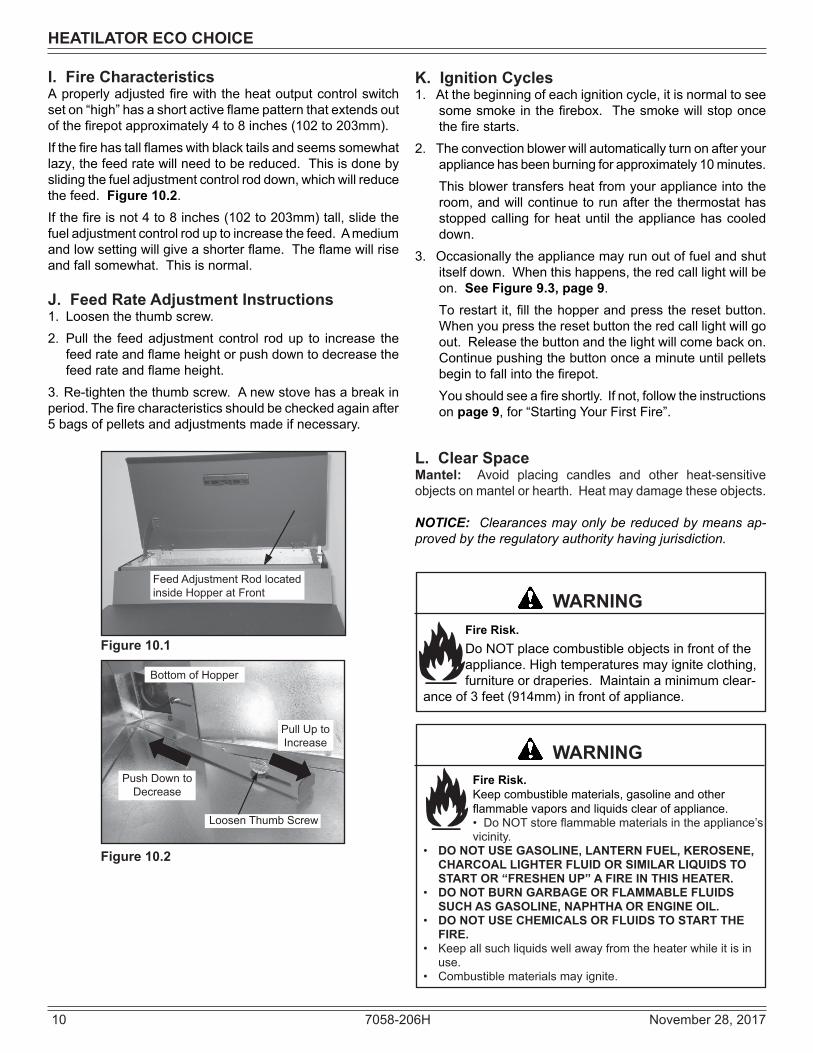
I. Fire CharacteristicsA properly adjusted fire with the heat output control switch set on “high” has a short active flame pattern that extends out of the firepot approximately 4 to 8 inches (102 to 203mm). If the fire has tall flames with black tails and seems somewhat lazy, the feed rate will need to be reduced. This is done by sliding the fuel adjustment control rod down, which will reduce the feed. Figure 10.2. If the fire is not 4 to 8 inches (102 to 203mm) tall, slide the fuel adjustment control rod up to increase the feed. A medium and low setting will give a shorter flame. The flame will rise and fall somewhat. This is normal.
J. Feed Rate Adjustment Instructions1. Loosen the thumb screw.2. Pull the feed adjustment control rod up to increase the
feed rate and flame height or push down to decrease the feed rate and flame height.
3. Re-tighten the thumb screw. A new stove has a break in period. The fire characteristics should be checked again after 5 bags of pellets and adjustments made if necessary.
Figure 10.1
Feed Adjustment Rod located inside Hopper at Front
Bottom of Hopper
Loosen Thumb Screw
Pull Up to Increase
Push Down to Decrease
Figure 10.2
K. Ignition Cycles1. At the beginning of each ignition cycle, it is normal to see
some smoke in the firebox. The smoke will stop once the fire starts.
2. The convection blower will automatically turn on after your appliance has been burning for approximately 10 minutes. This blower transfers heat from your appliance into the room, and will continue to run after the thermostat has stopped calling for heat until the appliance has cooled down.
3. Occasionally the appliance may run out of fuel and shut itself down. When this happens, the red call light will be on. See Figure 9.3, page 9. To restart it, fill the hopper and press the reset button. When you press the reset button the red call light will go out. Release the button and the light will come back on. Continue pushing the button once a minute until pellets begin to fall into the firepot.You should see a fire shortly. If not, follow the instructions on page 9, for “Starting Your First Fire”.
L. Clear SpaceMantel: Avoid placing candles and other heat-sensitive objects on mantel or hearth. Heat may damage these objects.
NOTICE: Clearances may only be reduced by means ap-proved by the regulatory authority having jurisdiction.
Fire Risk.Keep combustible materials, gasoline and other flammable vapors and liquids clear of appliance.• Do NOT store flammable materials in the appliance’s vicinity.
• DO NOT USE GASOLINE, LANTERN FUEL, KEROSENE, CHARCOAL LIGHTER FLUID OR SIMILAR LIQUIDS TO START OR “FRESHEN UP” A FIRE IN THIS HEATER.
• DO NOT BURN GARBAGE OR FLAMMABLE FLUIDS SUCH AS GASOLINE, NAPHTHA OR ENGINE OIL.
• DO NOT USE CHEMICALS OR FLUIDS TO START THE FIRE.
• Keep all such liquids well away from the heater while it is in use.
• Combustible materials may ignite.
WARNING
Fire Risk.Do NOT place combustible objects in front of the appliance. High temperatures may ignite clothing, furniture or draperies. Maintain a minimum clear-
ance of 3 feet (914mm) in front of appliance.
WARNING

November 28, 2017 7058-206H 11
HEATILATOR ECO CHOICE
M. Quick Start Guide
ECO CHOICE QUICK START GUIDE*Before you plug in this appliance, follow these instructions*
Once a fi re has been established in the unit, leave the unit burning on the “high” setting for 30 min-utes to allow the paint to cure.
Note: Odors and vapors will be released during this process.
*Open windows in the room for ventilation*
1 2
4 5 6
9
Remove hang tags from the door glass. Clean the glass. Remove the hardware pack and dessicant bag from the fi rebox area before your fi rst fi re.
Add pellets to the hopper and close the lid.
Open the fi rebox door and make sure the baffl es are in place.
Close the fi rebox door and plug the power cord into the wall receptacle.
Turn the thermostat on.
Turn the thermostat to off.
If the feed tube is empty or this is the fi rst fi re, add a handful of pellets to the fi repot.
*Do not add extra fuel to the fi repot if the feed tube has already been primed. Overfi lling the fi re-pot will cause smoky start-ups.
If the fi re dies out after a few minutes of operation it will be nec-essary to push the reset button to add more fuel.
3
7
The stove will feed pellets for a minute and stop. Once a fi re starts, the feed cycle will resume.
Note: Allow 5 minutes for ignition to take place.
8After 30 minutes have passed, turn the thermostat off and allow the unit to cool completely. Open the door and clean the fi repot according to the cleaning instructions found inside the hopper lid or owners manual. Close the door and set the thermostat to a desired temperature. Unit is now ready to resume normal operation.
10

12 7058-206H November 28, 2017
HEATILATOR ECO CHOICE
N. Frequently Asked QuestionsCONTACT YOUR DEALER for additional information
regarding operation and troubleshooting. Visit www.heatilator.com to find a dealer.
What causes my glass to become dirty?If the glass has white ash build up it is normal and the glass should be cleaned. If it is a black soot build up airflow through the unit may be restricted. The most often cause is overdue maintenance and cleaning. See “Maintaining and Servicing Appliance” in the owner’s manual.
How can I get more heat out of the appliance? The most often cause of diminished heat output is overdue maintenance and cleaning . See “Maintaining and Servic-ing Appliance” in the owner’s manual. If this still does not help, verify the correct settings for maximum heat output. See “Feed Rate Adjustment” under “Operating Instructions” in the owner’s manual.
What should I do if I smell smoke or there is ash/soot coming from the appliance? While there will always be some smoke smell from wood burning appliances (including pellet) you should investigate all venting to make sure it is sealed properly. Most vent-ing requires silicone to seal the seams. In addition most homes are built very tight today and with exhaust systems can create negative pressure in the home. See “Negative Pressure” under “Getting Started” in the owner’s manual if you have checked the venting but still have smoke coming from the appliance. For ash or soot check the above and the exhaust blower housing and seals. Why would my appliance run fine last winter but not start this fall? It is possible that the stove was not properly prepared for the Non-burn season. See “Trouble shooting” in the own-er’s manual.
Why would the metal on the inside of the appliance begin to flake? There are some pellet mills that get their raw materials from lumber mills that purchase logs that are transported in sea water. These pellets can have a higher salt content and cause the metals in the unit to corrode prematurely and deteriorate. If you are seeing any components inside the firebox deteriorate it is recommended to change pellet brands immediately.
Why does only the exhaust blower run when I unplug and plug back in my appliance? This is a Safety feature to prevent the unit from operating in an unsafe condition. Allow the unit to run and it will return to normal operation.
Is there a place to lubricate the blowers to quiet them down? The most often cause of noisy blowers is from the impellers becoming dirty over time. See “General Maintenance & Cleaning” under “Maintaining & Servicing Appliance” in the owner’s manual. No form of lubrication should ever need applied to the blowers.
Why are different components cycling on and off in my appliance at random? The selector switch on control box may be on the wrong setting. Refer to the Reference Materials section of our owner’s manual for details.
What is the metal object with the bend in it for that came inside the plastic bag? It is a clean-out tool used to help clean the fire pot and remove any jams in the rare event they occur in the feed tube.
Why is there a black residue building up on the outside of my home? Wind can cause this to happen. If the appliance is operat-ing correctly very little soot should ever exit the termination cap. Also check to be sure the venting is installed per the owner’s manual and local codes.
Do I need an outside air kit? Outside air is required for mobile home installs and in some jurisdictions. Refer to “Listing & Code Approvals”,“ Mobile Home Installation” and “ Appliance Set-up” owner’s manual. Also refer to local building codes.
I am seeing sparks coming out of my pipe (termination cap) outside is this safe? This is normal. As long as clearances to combustibles were followed this is safe.
My unit sounds like a freight train at times what can be done to eliminate this?This is referred to as Rumbling. Maintenance may be needed see “Maintaining and Servicing appliance” in the owner’s manual. Decrease fuel flow see “Feed rate adjust-ment” under Operating Instructions”. Why does my unit run fine on high, but shuts down on low and medium? Maintenance may be needed see “Maintaining and Servic-ing Appliance” See also “Trouble Shooting”.
Can I use another brand of wall thermostat or remote system?Yes, any remote/wall thermostat system that does not require power from the appliance should work.
I have no power to anything. Does this unit have a circuit breaker or fuse or a reset button? This unit has one serviceable fuse in the junction box and a reset button for the thermostat circuit.
Can I burn corn in my unit?Corn is not an approved fuel for the ECO units.
I’m thinking about going green (solar power) and need to know what the power consumption is on my Unit.PS50 115 VAC, 60 Hz, Start 5.1 Amps, Run 3.0 Amps. PS35 115 VAC, 60 Hz, Start 3.8 Amps, Run 1.3 Amps.CAB50 115 VAC, 60 Hz, Start 5.1 Amps, Run 3.0 Amps Where is the serial # of my unit is located? The serial # is located on the back of the stove.

November 28, 2017 7058-206H 13
HEATILATOR ECO CHOICE
3 Maintenance and Service
C. General Maintenance
1. Types of FuelDepending on the type of fuel you are burning will dictate how often you have to clean your fire pot. If the fuel you are burning has a high dirt or ash content, it may be necessary to clean the fire pot more than once a day. Dirty fuel will cause clinkers to form in the fire pot. A clinker is formed when dirt, ash or a non-burnable substance is heated to 2000°F (1093°C) and becomes glass-like. See “D” page 17 in this section for more details on fuels with high ash content.
Clinker
Figure 13.1 - Clinker
Shock and Smoke Hazard• Turn down thermostat, let appliance completely
cool and exhaust blower must be off. Now you can unplug appliance before servicing.
• Smoke spillage into room can occur if appliance is not cool before unplugging.
• Risk of shock if appliance not unplugged before servicing appliance.
CAUTION
Cleaning or Inspection Frequency Daily Weekly Monthly YearlyAsh Drawer Every 5 bags of fuel OR XAsh Removal from Firebox Every 5 bags of fuel or more
frequently depending on ash build-up
ORX
Blower, Exhaust More frequently depending on the fuel type
OR X
Blower, Convection Every 25 bags or more fre-quently depending on operat-ing environment.
ORX
Door Handle & Gasket Inspection Prior to heating season OR XExhaust Path, Drop Tube and Behind Baffles
Every 25 bags or more fre-quently depending on ash build-up
ORX
Firepot Cleaning Rod Every 1 bag of fuel OR XFirepot with Clean-out Tool Every 5 bags of fuel OR XFirebox - Prepare for Non-Burn Season At end of heating season OR XGlass When clear view of firepot
becomes obscureOR X
Hopper Every 50 bags of fuel OR XTop Vent Adapter More frequently depending on
ash build-upOR X
Venting System Every 3 tons or more fre-quently depending on the fuel type
ORX
B. Quick Reference Maintenance Chart
Follow the detailed instructions found in this section for each step listed as referenced in the chart below.
NOTICE: These are recommendations. Clean more frequently if you encounter heavy build-up of ash at the recommended interval or you see soot coming from the vent. Not properly cleaning your appliance on a regular basis will void your warranty.
A. Proper Shutdown Procedure
This pellet heater has a manufacturer-set minimum low burn rate that must not be altered. It is against federal regulations to alter this setting or otherwise operate this pellet heater in a manner inconsistent with operating instructions in this manual.

14 7058-206H November 28, 2017
HEATILATOR ECO CHOICE
3. Ash Removal from Firebox• Frequency: Weekly or more frequently depending on
ash build-up.• By: Homeowner a. There must not be any hot ashes in the firebox during
cleaning so allow the appliance to completely cool. The firebox ash should be removed every time the exhaust path is cleaned. Frequent cleaning of the ash in the firebox will help slow down the build-up of ash in the exhaust blower and vent system.
b. Vacuum out the firebox thoroughly on both sides of the firebox and the floor and ceiling. The ash drawer should be emptied every time you clean the firebox. Remember to place the ash and debris into a metal or non-combustible container. See Disposal of Ashes. (Pg 15)
c. Always have the ash drawer in place before pulling the firepot cleaning rod, otherwise the ashes will fall down and fill the outside air opening and the appliance will produce soot out of the exhaust and will affect efficiency.
2. Cleaning Firepot with Cleaning Rod & Firepot Clean-Out Tool;
• Frequency: Daily or more often as needed• By: Homeowner a. The appliance must be in complete shutdown and cool
and the exhaust blower off. If you are just cleaning the firepot, there is no need to unplug the appliance.
b. Locate the firepot cleaning rod on the right side of the appliance. Figure 14.1. When you pull the cleaning rod straight out it will slide open the firepot floor to allow the ashes to be deposited in the ash drawer. You will see the light color painted area on the cleaning rod to let you know the rod is in OPEN position. Figure 14.2.
c. Pull the firepot cleaning rod OUT and IN a couple of times to help shake debris loose. If the rod is hard to pull, it may be necessary to use your firepot clean-out tool to chip away material that has built up on the bottom plate of the firepot and to push out any clinkers while in the open position.
d. To close the firepot floor: slightly raise the cleaning rod and then push it back into place. If you have closed the cleaning rod properly (pushed all the way in) you will not see any of the light color painted area. Figure 14.2.
e. Always have the ash drawer in place before pulling the firepot cleaning rod, otherwise the ashes will fall down and fill the outside air opening and the appliance will produce soot out of the exhaust and will affect efficiency.
Firepot Cleaning Rod
Figure 14.1
Figure 14.2
CLOSED PositionNo light color paint is visible
Lift up and push closed
OPEN Position. Light color painted area visible
WARNING
Fire Risk• NEVER pull firepot cleaning rod out when appliance is operating.
• Cleaning Rod MUST be completely pushed in before operating appliance.
•. Hot pellets may fall into ashpan and start a fire or mis-starts due to lack of vacuum.
WARNING
Burn Risk• NEVER remove ash drawer while appliance is operat-
ing.
4. Cleaning Ash Drawer• Frequency: Weekly or every 5 bags of fuel• By: Homeowner a. There must not be any hot ashes in the ash drawer when
you empty it, so allow the appliance to completely cool. b. Locate the ash drawer underneath the firepot. Slide the
ash drawer straight out. Empty into a non-combustible container and re-install the ash drawer. See Disposal of Ashes. (Pg 15)
b. Always have the ash drawer in place before pulling the firepot cleaning rod, otherwise the ashes will fall down and fill the outside air opening and the appliance will produce soot out of the exhaust and will affect efficiency.
Pull out Ash Drawer & Dispose of Ashes in Non-Combustible Container
Ash Drawer
Figure 14.3

November 28, 2017 7058-206H 15
HEATILATOR ECO CHOICE5. Disposal of Ashes• Frequency: As needed• By: Homeowner
Ashes should be placed in a metal container with a tight-fitting lid. The closed container of ashes should be placed on a non-combustible floor or on the ground, well away from all combustible materials, pending final disposal. If the ashes are disposed of by burial in soil or otherwise locally dispersed, they should be retained in the closed container until all cinders have been thoroughly cooled.
Figure 15.1
Baffles Removed
Exhaust Path and Blower Impellers
Drop Tube
6. Cleaning the Exhaust Path, Baffles & Drop Tube• Frequency: Monthly or every 25 bags or more fre-
quently depending on ash build-up.• By: Homeowner a. Appliance must be completely cool. b. Open the door and remove the center baffle first and
then the right and left baffles. See Baffle Removal Instructions on page 23. Thoroughly vacuum the exhaust path and drop tube and continue throughout the rest of the firebox. Also vacuum the front and back of the baffles.
c. Also vacuum the combustion blower impellers or use a soft brush to remove any ash build-up.
Replace the right and left baffles and then the center baffle and close and latch the door.
WARNINGDisposal of Ashes• Ashes should be placed in metal container with tight
fitting lid.• Ashes should be retained in closed container until all
cinders have thoroughly cooled.
7. Cleaning the Hopper• Frequency: Monthly or after burning 50 bags of fuel• By: HomeownerAfter burning approximately 50 bags of fuel you will need to clean the hopper to prevent sawdust build-up. A combination of sawdust and pellets on the bottom end of the auger reduces the amount of fuel supply to the firepot. This can result in nuisance shutdowns and mis-starts.
a. The appliance must be in complete shutdown. Allow the appliance to completely run out of pellets and cool down.
b. Empty the hopper of any remaining pellets. c. Vacuum the hopper and feed tube.
NOTE: Hearth & Home Technologies recommends to use a heavy duty vacuum cleaners specifically designed for solid fuel appliance cleaning.
8. Soot and Fly Ash: Formation & Need for Removal in Exhaust Venting System.
• Frequency: Yearly or more frequently depending on ash build-up.
• By: Qualified Service Technician/HomeownerBe sure the appliance is allowed to cool, has been unplugged and the exhaust blower is off.The products of combustion will contain small particles of fly ash. The fly ash will collect in the exhaust venting system and restrict the flow of the flue gases. At start-up if there is incomplete combustion, or if there is a shutdown or incorrect operation of the appliance it will lead to some soot formation. This will collect in the exhaust vent-ing system. The venting (chimney) system may need to be cleaned at least once a year or more often depending upon the qual-ity of your fuel or if there are any horizontal pipe sections. Ash will build up more quickly in the horizontal sections and elbows.
9. Door Handle Inspection• Frequency: Monthly or prior to heating season• By: HomeownerThe gasket between the glass and firebox should be inspected periodically to make sure there is a good seal. Check door handle for smooth cam operation.
Locknut
Door Cross Section (example) Latch Cam
Spacing Washers
Square Key
Door Handle
Spring Handle
Figure 15.2

16 7058-206H November 28, 2017
HEATILATOR ECO CHOICE
10. Cleaning the Glass
• Frequency: When clear view of the firepot becomes obscure
• By: Homeowner a. Appliance must be completely cool before cleaning
glass. b. Vacuum fly ash from glass and door rope. c. Use a damp paper towel or any non-abrasive glass
cleaner. Wipe off with dry towel.
Handle glass assembly with care.
When cleaning glass:• Avoid striking, scratching or slamming
glass.• Do NOT clean glass when hot.
CAUTION
• Do NOT use abrasive cleaners.• Refer to maintenance instructions.
Handle glass with care.• Inspect the gasket to ensure it is
undamaged.• Do NOT strike, slam or scratch glass.• Do NOT operate appliance with glass
assembly removed.
WARNING
• Do NOT operate with glass cracked, broken or scratched.
11. Cleaning Exhaust Blower - Requires No Lubrication
• Frequency: Yearly or more frequently depending on ash build-up
• By: Homeowner or Qualified Service Technician a. Be sure the appliance is allowed to cool, has been
unplugged and the exhaust blower is off. b. Follow the directions for cleaning the exhaust path found
on page 15. c. If unable to thoroughly clean the blower through this
access, then follow the directions on page 22 for direct access to the exhaust blower.
d. Vacuum the blower’s impellers. Use care not to bend or damage the blower fins.
NOTE: Hearth & Home Technologies recommends to use a heavy duty vacuum cleaners specifically designed for solid fuel appliance cleaning.
12. Cleaning Convection Blower - Requires No Lubrication
• Frequency: Yearly or more frequently depending on Dust/Dirt build-up
• By: Homeowner or Qualified Service Technician a. Be sure the appliance is allowed to cool and has been
unplugged. b. Follow the directions on page 21 for direct access to
the convection blower. c. Sweep or vacuum out any build-up. Use a brush or
compressed air to loosen dirt if needed.
13. Cleaning the Top Vent Adapter• Frequency: Yearly or more frequently depending on
ash build-up• By: Homeowner a. The appliance must be in complete shutdown and
the exhaust blower should be off. Allow the appliance to completely cool down.
b. Open the clean-out cover. Figure 16.1. c. Sweep or vacuum out any ash build-up.
Figure 16.1
Clean-Out Cover
14. Preparing Firebox for Non-Burn Season• Frequency: Yearly• By: Homeowner a. Be sure the appliance is allowed to cool, has been
unplugged and the exhaust blower is off. b. Remove all ash from the firebox and vacuum thoroughly. c. Paint all exposed steel, including cast-iron.
• Purchase paint from your local dealer. • Must use a high-temperature paint made specifi-
cally for heating appliances.

November 28, 2017 7058-206H 17
HEATILATOR ECO CHOICE
D. High Ash Fuel Content Maintenance• Frequency: As needed• By: HomeownerPoor quality pellet fuel, or lack of maintenance, can create conditions that make the firepot fill quickly with ashes and clinkers. This condition makes the appliance susceptible to overfilling the firepot with pellets which may result in smoking, sooting and possible hopper fires. Figure 17.1 shows an example where the firepot overfills, pellets back up into the feed tube and ash has accumulated in the firebox. An inefficient and non-economical method of burning of fuel caused by poor quality pellet fuel is shown in Figure 17.2. The correct flame size when good quality, premium pellet fuel is burned is shown in Figure 17.3.If the ash buildup exceeds the half way point in the firepot IMMEDIATE ATTENTION AND CLEANING IS REQUIRED.
WARNINGFire Risk• High ash fuels, or lack of maintenance, can cause the firepot to overfill. Follow proper shutdown procedure if ash buildup exceeds halfway point in firepot. • Failure to do could result in smoking, sooting and
possible hopper fires.
Figure 17.3
Figure 17.1
Figure 17.2
Correct Flame HeightYellow/White in Color
Incorrect Flame HeightTall, Lazy Flame Orange in Color
Pellets Back-up in Feed Tube
Ash build-up in Firebox
Firepot Overfills
E. Soot or Creosote Fire Establish a routine for the fuel, wood burner and firing tech-nique. Check daily for creosote build-up until experience shows how often you need to clean to be safe. Be aware that the hotter the fire the less creosote is deposited, and weekly cleaning may be necessary in the mild weather even though monthly cleaning may be enough in the coldest months. Contact your local municipal or provincial fire authority for information on how to handle a chimney fire.
In the event of a soot or creosote fire, close the firebox door, exit the building immediately and contact the proper fire authorities. DO NOT under any circumstances re-enter the building.

18 7058-206H November 28, 2017
HEATILATOR ECO CHOICE
With proper installation, operation, and maintenance your appliance will provide years of trouble-free service. If you do experience a prob-lem, this troubleshooting guide will assist a qualified service person in the diagnosis of a problem and the corrective action to be taken. This troubleshooting guide can only be used by a qualified service technician.
4 Troubleshooting Guide
Symptom Possible Cause Corrective ActionPlug in appliance - No response.
No Power to outlet.7 amp fuse defective or blown#3 snap disc tripped or defective.Control box is loose or defective.
Check circuit breaker at service panel.Replace fuse.Reset or replace snap disc.Reset or replace control box.
Call light on. No fire.No fuel in firepot.
Out of fuel.#2 snap disc may be defective or tripped.Vacuum switch not closing, no vacuum.Hopper lid open.Defective hopper switch.
Missing or out of place hopper switch magnet. (CAB50)
Control box defective.
Check hopper. Fill with fuel.Reset or replace snap disc.Check exhaust blower is plugged in and operat-ing.Check vacuum switch is plugged in.Check vacuum hose is in good condition, clear and connected at both ends.Check thermocouple is in good condition and plugged in properly.Make sure venting system is clean.Make sure front door is closed.Check vacuum switch fitting on back of auger tube for blockage.Replace control box.Close Hopper Lid.Check hopper switch operation.Check/adjust magnet position.
Call light on. No fire.Partially burned fuel in firepot.
Firepot is dirty (missed ignition).
Vent system plugged.
Igniter chamber blocked
Clean firepot. Make sure there is no clinker in the firepot. Close firepot bottom plate/Clinkers may have to be broken up with firepot clean-out tool or other means.Check flue vent for obstructionCheck if firepot floor is closed all the way
Clear igniter chamber using firepot clean-out tool
Call light on. No fire.Unburned pellets in firepot.
Firepot is dirty.
Igniter chamber blocked.Igniter not working.
Control box defective.
Firepot floor open.
Clean firepot. Make sure there is not a clinker in the firepot. Clinkers may have to be pushed out of firepot with firepot clean-out tool or other means.Clear igniter chamber using firepot clean-out tool.
Remove ash drawer to see if igniter is glowing red on start-up.Check igniter wires for good connection.Use a multimeter to check igniter for continuity.Replace igniter using instructions in manual.
Replace control box.
Slow or smoky start-up. Firepot is dirty.Igniter chamber blocked.Firepot floor partially open.
Excessive amount of fuel at start-up.
Clean firepot. Make sure there is not a clinker in the firepot. Clinkers may have to pushed out of firepot with firepot clean-out tool or other means. Check if firepot floor is closed all the wayReduce feed rate using feed rate adjustment control rod located inside hopper. Close firepot floor.Clear igniter chamber using firepot clean-out tool.

November 28, 2017 7058-206H 19
HEATILATOR ECO CHOICE
Symptom Possible Cause Corrective ActionSlow or smoky start-up (Cont’d)
Dirty exhaust and/or venting system.
Wet fuel / poor quality fuel
Check for ash build up in unit, includ-ing behind rear panels, firebox, exhaust blower and venting.Replace fuel
Feed system fails to start
Amber light blinking
Out of fuel.#2 snap disc may be defective or tripped.Vacuum switch not closing. No vacuum.
Defective vacuum switch
Feed system jammed or blocked.
Feed spring not turning with feed motor.
Feed motor defective or not plugged in.
Thermocouple may have failed. Amber light will blink 3 times, pauses, and keeps repeating
Check hopper, fill with fuel.Reset or replace snap disc
Check vacuum fitting on auger tube for restrictions. Check door rope and replace if necessary.Check exhaust blower is plugged in and operating.Check vacuum switch is plugged in. Check vacuum hose is in good condition, clear and connected at both ends.Check thermocouple is in good condition and plugged in properly.Make sure venting system is clean.NOTE: High winds blowing into the venting system can pressurize the firebox causing loss of vacuum.Replace vacuum switchEmpty hopper of fuel. Use a wet/dry vacuum cleaner to remove remaining fuel, from hopper, including feed tube.Check feed chute for obstructions.Remove feed assembly & check for obstruction.
Check that set screw is tight on feed spring shaft at end of feed motor.Check connections on feed motor, replace if defective.
Replace Thermocouple
No call light. Unit does not begin start sequence.
Thermostat not set to a high enough tempera-ture.Snap disc #3 tripped or defective.No power.Fuse blown.Connections at thermostat and/or appliance not making proper contact.
Defective thermostat or thermostat wiring.
Control box defective.
Adjust thermostat above room tempera-ture.Reset snap disc or replace if defective.Connect to power.Replace fuse.Check connections at thermostat and appliance. Temporarily jump connection to verifyReplace thermostat or wiring.NOTE: To test thermostat and wiring, use a jumper wire at the thermostat block on the unit to by-pass thermostat and wiring.
Replace control box.
Unit fails to shut off. Call light on. Turn thermostat off.If call light does not go out, disconnect thermostat wires from unit. If call light does go out, thermostat or wires are defective.

20 7058-206H November 28, 2017
HEATILATOR ECO CHOICE
Symptoms Possible Cause Corrective ActionConvection blower fails to start.
#1 snap disc defective.
Blower not plugged in.
Blower is defective or object jammed in impeller.
Control box is defective.
Replace snap disc.
Check that blower is plugged into wire harness.
Replace blower.
Replace control box.Exhaust blower fails to start.
Blower not plugged in.
Intermittent electrical connection.Obstruction in blower.
Blower is defective.
Control box is defective.
Check that blower is plugged into wire harness.Verify fit of plug to outletClean exhaust system.
Replace blower.
Replace control box.
Exhaust blower does not shut off.
Control box is defective. Replace control box.
Large, lazy flame, orange color. Black ash on glass.
Dirty appliance.Poor fuel quality, high ash content.
Excessive amount of fuel.
Control box is on the wrong setting.
Clean unit, including firepot and venting system. Clean exhaust path. Try a different brand of pellets.
Reduce feed rate using feed rate adjustment control rod located inside hopper.
“See owner’s manual for correct setting for your model and how to adjust control box setting.
Nuisance shutdowns. Low flame.
Sawdust buildup in hopper.
Feed motor is reversing.
Feed motor is weakFeed bearing adjustmentDefective thermocouple.
Defective control box.
Firepot more than 1/2 full.
Increase feed by opening feed rate adjust-ment control rod located inside hopper.
Clean hopper, see page 10.
Check for good connections between feed motor and wire harness.Test feed motor torque.Adjust feed bearingReplace thermocouple.
Replace control box.
See page 17 for detailed instructions for “High Ash Fuel Content Management”Reduce feed rate
Appliance calls for heat.Call light illuminates.Exhaust blower starts.No feed or igniter.
Thermocouple is defective or not properly plugged in.
Defective control box
Check connections on thermocouple or replace if defective.A flashing yellow light on the control box indicates a problem with the thermocouple.
Replace control box.
November 28, 2017 7058-206H 21
HEATILATOR ECO CHOICE
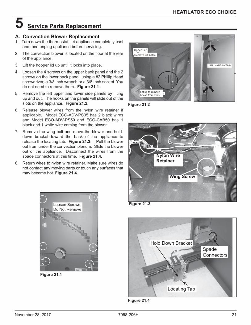
A. Convection Blower Replacement1. Turn down the thermostat, let appliance completely cool
and then unplug appliance before servicing.2. The convection blower is located on the floor at the rear
of the appliance.3. Lift the hopper lid up until it locks into place.4. Loosen the 4 screws on the upper back panel and the 2
screws on the lower back panel, using a #2 Phillip Head screwdriver, a 3/8 inch wrench or a 3/8 Inch socket. You do not need to remove them. Figure 21.1.
5. Remove the left upper and lower side panels by lifting up and out. The hooks on the panels will slide out of the slots on the appliance. Figure 21.2.
6. Release blower wires from the nylon wire retainer if applicable. Model ECO-ADV-PS35 has 2 black wires and Model ECO-ADV-PS50 and ECO-CAB50 has 1 black and 1 white wire coming from the blower.
7. Remove the wing bolt and move the blower and hold-down bracket toward the back of the appliance to release the locating tab. Figure 21.3. Pull the blower out from under the convection plenum. Slide the blower out of the appliance. Disconnect the wires from the spade connectors at this time. Figure 21.4.
8. Return wires to nylon wire retainer. Make sure wires do not contact any moving parts or touch any surfaces that may become hot Figure 21.4.
5 Service Parts Replacement
Loosen Screws, Do Not Remove
Figure 21.1
Figure 21.2
Figure 21.3
Figure 21.4
Locating Tab
Hold Down BracketSpade Connectors
Nylon WireRetainer
Wing Screw
Upper Left Panel
Lower Left Panel
Lift Up and Out of Slots
Remove left baffle
Lift up to remove hooks from slots

22 7058-206H November 28, 2017
HEATILATOR ECO CHOICE
B. Exhaust Blower Replacement1. Turn down the thermostat, let appliance completely cool
and then unplug appliance before servicing.2. Remove both upper and lower right side curtains. Figure
22.2. on page 22. 3. Disconnect 2 white wires from the white and blue wires of
the exhaust blower.4. There is a removable plate on the exhaust blower.
Depending on the model, use a 1/4 inch socket, or 1/4 inch Nut Driver or #2 Phillips Head screw driver to loosen the 6 screws in the keyhole shaped holes and rotate the plate. It is only necessary to loosen screws. Figure 22.1.
5. Remove the exhaust blower and gasket.6. Check for degradation on the gasket and replace if nec-
essary using the gasket included in the kit.7. Re-install in reverse order.
Figure 22.1
Exhaust Blower
C. Snap Disc ReplacementsSnap Disc #1 - Convection Blower1. Turn down thermostat, let appliance cool completely if
running. Then unplug appliance before servicing. 2. Using #2 Phillips screwdriver, 3/8” wrench, or 3/8” socket
loosen the three screws that hold the right upper and lower side panels in place. You do not need to remove the screws. Remove side panels by lifting up and out.
3. Snap disc #1 is located on the convection plenum below the feed motor. Figure 22.1.
4. It has two purple wires attached to it with 1/4 inch female spade terminals.
5. Disconnect the two wires from the snap disc. Using a #2 Phillips screwdriver, remove the two screws securing the snap disc to the appliance.
6. Re-install in reverse.
Snap Disc #2 - Fuel Delivery Interrupt1. Turn down thermostat, let appliance cool completely if
running. Then unplug appliance before servicing. 2. Using #2 Phillips screwdriver, 3/8” wrench, or 3/8” socket
loosen the three screws that hold the right upper and lower side panels in place. You do not need to remove the screws. Remove side panels by lifting up and out.
3. Snap disc #2 is located on the convection plenum in the center of the appliance above the convection blower. Figure 22.2.
4. It has a black wire and an orange wire attached to it with 1/4 inch female spade terminals.
5. Disconnect the two wires from the snap disc. Using a #2 Phillips screwdriver, remove the two screws securing the snap disc to the appliance.
6. Re-install in reverse.
Snap Disc #3 - Feed Motor - Manual Reset1. Turn down thermostat, let appliance cool completely if
running. Then unplug appliance before servicing. 2. Using #2 Phillips screwdriver, 3/8” wrench, or 3/8” socket
loosen the three screws that hold the right upper and lower side panels in place. You do not need to remove the screws. Remove side panels by lifting up and out.
3. Snap disc #3 is located on the bracket on the feed tube near the feed motor. Figure 22.1.
4. It has a two gray wires attached to it with 1/4 inch female spade terminals.
5. The locating bracket is attached to the feed tube with an 8 X 32 wing nut. Remove the wing nut to detach the bracket from the feed tube.
5. Disconnect the two wires from the snap disc. 6. Using a #2 Phillips screwdriver, remove the screw secur-
ing the snap disc to the bracket. Figure 23.1 on page 23.7. Re-install in reverse.
Figure 22.2
Snap Disc #1
Snap Disc #3
Snap Disc #2

November 28, 2017 7058-206H 23
HEATILATOR ECO CHOICE
Figure 23.1
Remove Screw
Snap Disc Bracket
D. Igniter Replacement 1. Shut down the appliance by turning down the thermostat
and let the appliance completely cool down. After the appliance has cooled down, unplug it and remove the ash drawer.
2. The wire leads to the igniter are connected to the wire harness with 1/4 inch male / female spade connectors.
Follow the directions on page 21 to remove the upper and lower right side panels to expose the spade connectors.
Disconnect the spade connectors and remove the igniter from the chamber. Loosen thumb screw and slide igniter out.
3. Install new igniter into the chamber and tighten thumb screw. The wires MUST route through the wire retainer hook and then re-connect the wires to the 2 leads with the spade connectors. Figure 23.2.
4. Double check that the igniter wires are clear of any movement, i.e. ash drawer, firepot cleaning rod, , etc.
5. Re-install the ash drawer and side panel and re-connect the power.
E. Baffle Removal & Replace1. Shut down the appliance by turning down the thermostat
and let the appliance completely cool down.2. Remove the center baffle first by using the handle at the
top of the baffle and pull up and then towards you. The hooks on the baffle will slide out of the slots in the bracket. Figure 23.3.
3. Remove the left baffle and then the right baffle by pulling up and then towards you. The left and right baffles have similar hooks and slots. Figures 23.4 and 23.5.
4. Re-install the baffles in reverse order. Be careful to insert the hooks in their respective slots. Be sure the baffles are completely secure/seated (close, if not touching, the fire-box floor).
Firepot
Igniter
Igniter Chamber
Thermocouple & Thermocouple Cover
Thumb Screw
Firepot Cleaning RodIgniter Wires
MUST BE ROUTED Through Wire Retainer Hook
Figure 23.2
Figure 23.3
Figure 23.4
Figure 23.5
Use handle at top of center baffle to pull up and then towards you.
Remove left baffle
Lift up to remove hooks from slots
Remove right baffle

24 7058-206H November 28, 2017
HEATILATOR ECO CHOICE
• Glass is 5mm thick high temperature heat-re-sistant ceramic glass.
• DO NOT REPLACE with any other material.
• Alternate material may shatter and cause injury.
WARNING
F. Glass Replacement1. Open the door from the appliance by lifting door off of hinge
pins and lay on a flat surface face down.2. Using a Phillips Head screw driver, remove the 4 brackets
and set aside. Figure 24.1.3. Remove old glass and replace with the new glass.4. Re-install the brackets using the same screws.
Glass Assembly
1
2
3
4
Remove the 4 brackets outlined in the diagram
Figure 24.1

November 28, 2017 7058-206H 25
HEATILATOR ECO CHOICE
6 Reference Materials
2. Convection BlowerThe convection blower is mounted at the bottom rear of the appliance. There are 2 impellers, one on each side of the motor. The convection blower pushes heated air through the heat exchange system into the room. 3. Exhaust BlowerThe exhaust blower is mounted on the right side of the appliance. The exhaust blower is designed to pull the exhaust from the appliance and push it out through the venting system. 4. Feed SystemThe feed system is located on the right side of the appliance and can be removed as an entire assembly. The assembly includes the feed motor, mounting bracket, bearing and feed spring (auger). The hollow feed spring (auger) pulls pellets up the feed tube from the hopper area and drops them down the feed chute into the fire pot. 5. Fire potThe fire pot is made of high quality ductile iron and has a cleaning pull-out rod. The floor of the fire pot opens for cleaning when you pull out the rod. Be sure that the floor returns to a completely closed position or your appliance will not operate properly.6. FuseThe fuse is located on the side of the junction box above to the red call light. The fuse will blow should a short occur and shut off power to the appliance.7. Heat Output SwitchThe heat output switch is located on the upper right back panel. The function of the heat output switch is to regulate the burn rates; low, medium and high settings.8. Hopper SwitchThe hopper switch is located in the upper right hand corner of the hopper. This switch is designed to shut down the feed motor whenever the hopper lid is opened.9. IgniterThe igniter is mounted on the base of the fire pot. Combustion air travels over the red hot igniter creating super heated air that ignites the pellets. 10. Junction Box And Wiring HarnessThe junction box is located on the lower left side of the appliance, behind the left side panel. The junction box and wiring harness are replaced as one component.11. Power SupplyThe power outlet is located behind the control box on the back of the appliance, lower left corner. Check the wall receptacle for 120 volt, 60 Hz (standard current). Make sure the outlet is grounded and has the correct polarity. A good surge protector is recommended.
When describing the location of a component, it is always AS YOU FACE THE FRONT OF THE APPLIANCE.
A. Component Functions
1. Control Box a. The control box is located on the lower left side of the
appliance, behind the lower left side panel and above the junction box.
b. There is a light located inside of the control box. The internal light will turn green when the appliance has reached a temperature of 200°F (93°C) in the fire pot. and will turn red when it reaches 600°F (315°C).
c. There is also an internal blue light located in the control box. When you plug in the appliance the blue light will automatically start blinking. For model PS35 the blue light should flash 7 times every 10 seconds for the first 60 seconds after power up. For models PS50 and CAB50 it should blink 2 times.
To set your control board on the correct number: • Unplug the appliance.• Using #2 Phillips screw driver, 3/8” wrench, or 3/8”
socket loosen the three screws that hold the right upper and lower side panels in place. You do not need to remove the screws. Remove side panels by lifting up and out.
• Use a #2 Phillips screw driver to remove the control box retainer bracket and lift control box out of the junction box.
• Using a ¼ inch flat head screw driver turn the rotary switch until the desired number is showing on the dial.
• Re install control box and plug in appliance.• To confirm your selection is correct count the number
of times the blue light flashes.Example: If you are on setting 2 the control box will flash 2
times every 10 seconds for 1 minute. See chart below for correct control box setting for your model.
E
NOTE: Do NOT open the control box. This will void the warranty. If you need to plug in or remove the control box you must first unplug the appliance.
Model Factory Control Board SettingPS 35 #7 (7 Flashes)PS50 / CAB50 #2 (2 Flashes)
Rotary Switch

26 7058-206H November 28, 2017
HEATILATOR ECO CHOICE
12. Red Call LightThe red call light is on the side of the junction box, below the fuse. The function of the red call light is to indicate that the thermostat is calling for heat.13. Reset ButtonThe reset button is located on the back of the appliance in the upper right corner below the heat output control switch. The function of the button is to momentarily open the thermostat circuit, which restarts the system. 14. ThermocoupleThe thermocouple is located on top of the firepot inside the thermocouple cover (ceramic protection tube). The thermocouple sends a millivolt signal to the control box indicating the preset temperatures of the green and red lights have been obtained.15. ThermostatThe appliance is designed to run on a 12 volt AC thermostat. The heat anticipator should be set on the lowest setting available. 16. Snap Disc #1 (Convection Blower) 110°FSnap disc #1 is located on the right side of the appliance behind the right side panel. There are 2 purple wires connected to it. This snap disc turns the convection blower on and off as needed. Power is always present at snap disc #1.
17. Snap Disc #2 (Fuel Delivery Interrupt) 175°FSnap disc #2 is located on the center of the convection plenum above the convection blower. There is an orange and a black wire connected to it. This snap disc will turn off the feed system which will turn off the appliance if an over fire condition should occur or if the convection blower should fail to operate. If this occurs you will have to manually reset the snap disc.18. Snap Disc #3 (Back Burn Protector) 250°FSnap disc #3 is mounted on the back of the auger tube in the center of the appliance and has a reset button. There are two gray wires connected to it. To access it remove the right side panel. If the fire tries to burn back into the feed system or push exhaust up the feed tube, this snap disc will shut the entire system off. This disc must be manually reset.19. Vacuum SwitchThe vacuum switch is located on the lower right side of the appliance behind right side panel. There are two red wires attached to it. This switch turns the feed system on when vacuum is present in the firebox. The vacuum switch is a safety device to shut off the feed motor if the exhaust or the heat exchanger system is dirty or plugged or if the firebox door is open. 20. Wiring HarnessSee Figure 26.1 below.
Figure 26.1
1B
3/CD
5/EF
7/H14
8K
10M
12/NP
S
M
M
M
NL
G
Thermocouple
Heat Output Switch
Thermostat Block
Vacuum Switch
Snap Disc #2
Capacitor Feed Motor
Snap Disc #1
Convection Motor
Combustion Blower
Call Light
Reset Button
Snap Disc #3
Fuse
Igniter
Green
Yellow
Red
Red Red
Orange
Orange
White
Black
Black
BlackYellowRedPurpleGrey
Grey
BlueBlackBlack
Blue
Hopper Switch

November 28, 2017 7058-206H 27
HEATILATOR ECO CHOICE
Figure 27.2
Figure 27.1
Figure 27.3
Control Box
Junction Box
Red Call Light
Fuse
Convection Blower
LOCATED BEHIND LEFT SIDE PANELS Feed Motor
Vacuum Switch
Combustion Blower
LOCATED BEHIND RIGHT SIDE PANELS
Back of Appliance
Power Outlet
Terminal Block Center 2 Screws for Thermostat Wires
Heat Output Switch
Reset Button
B. Component Locations

28 7058-206H November 28, 2017
HEATILATOR ECO CHOICE
Service Parts
Beginning Manufacturing Date: Apr 2010 Ending Manufacturing Date: Active
ECO-ADV-PS35
Part number list on following page.
Free Standing Pellet Stove
1
2
45
67
3
8
910
14
15
16
12
13
1117
18
1920 21
23
25
24
26
2930
28
27
22
11/17
C. Exploded Drawings & Service Parts - PS35

November 28, 2017 7058-206H 29
HEATILATOR ECO CHOICE
Service Parts
Beginning Manufacturing Date: Apr 2010 Ending Manufacturing Date: Active
ECO-ADV-PS35
IMPORTANT: THIS IS DATED INFORMATION. Parts must be ordered from a dealer or distributor. Hearth and Home Technologies does not sell directly to consumers. Provide model number and serial number when requesting service parts from your dealer or distributor.
Stocked at Depot
Item Description Comments Part Number1 Hopper Lid Assembly SRV7058-0092 Handle, Hopper Lid SRV200-01103 Side Curtain, Left SRV7058-1254 Baf e Assembly SRV7058-026 Y5 Door Assembly SRV7058-014
Door Handle Assembly SRV7058-030 YGasket, Glass Tape, 3/4” X 1/8” 5 Ft 832-0460 YGlass Assembly SRV7058-015 YKey Latch, Cam SRV430-1151Hinge Pin, 1/2” Nickel SRV430-5320Rope, Door, 3/4” X 84” 832-1680 Y
6.1 Thermocouple Protection TubeSRV7034-186 Y
Pkg of 10 SRV7034-186/106.2 Half Clip 7000-3216.3 Thermocouple 812-4470 Y7 Firepot Assembly SRV7034-072B Y
Gasket, Firepot SRV7034-190 Y8 Firepot Bottom SRV7034-153 Y9 Rail, Auto-Clean SRV7034-152 Y
10 Spring Pkg of 4 7000-513/4 Y11 Hitch Pin Clip 3/32 Pkg of 10 7000-374/10 Y12 Pull Rod SRV7058-141
13 Heating Element Assembly 18” (Loop Igniter)Pkg of 1 SRV7000-462 YPkg of 10 SRV7000-462/10 Y
14 Ash Pan Assembly SRV7058-013Heatilator Logo 4021-049
15 Pedestal Side Qty 2 req SRV7058-15316 Blower, Convection 812-4900 Y17 Wire Harness SRV7058-150 Y18 Blower Retainer SRV7058-14819 Control Board 3 Speed Eco-Choice SRV7058-188 Y20 Latch Backing Plate SRV7058-15521 Blower, Exhaust Combustion 812-4400 Y
Additional service parts on following page
6.16.36.2
#6 Thermocouple Assembly

30 7058-206H November 28, 2017
HEATILATOR ECO CHOICE
Service Parts
Beginning Manufacturing Date: Apr 2010 Ending Manufacturing Date: Active
ECO-ADV-PS35
IMPORTANT: THIS IS DATED INFORMATION. Parts must be ordered from a dealer or distributor. Hearth and Home Technologies does not sell directly to consumers. Provide model number and serial number when requesting service parts from your dealer or distributor.
Stocked at Depot
Item Description Comments Part Number22 Gasket, Exhaust Combustion Blower SRV240-0812 Y
Gasket, Combustion Blower, Round 812-4710 Y23 Casting, Exhaust Transition 180-0190
24 Snap discs24.1 Snap Disc, 110-20 ( #1 ) Right SRV230-1220 Y24.2 Snap Disc Manual Reset ( #2 ) Left SRV230-1960 Y25 Feed Assembly SRV7058-007 Y
Feed Bearing SRV7000-598 YFeed Motor 812-4421 YFeed Spring Assembly (Only) SRV7001-046 Y
Gasket, Feed Motor SRV7034-14426 Snap Disc ( #3 ) SRV230-1290 Y27 Side Curtain, Right SRV7058-12428 Vacuum Switch SRV7000-531 Y29 Hopper Switch SRV7000-612 Y30 Bumper, Rubber Pkg of 12 SRV224-0340/12 Y
Fuse, 7 Amp, Junction Box Pkg of 10 812-0380/10 YComponent Pack SRV7058-019
Cleanout Tool 414-1140 YDVD No longer available 7058-187Harness, Thermostat Wire 230-0810Power Cord 812-1180 YThermostat Mechanical 812-3760 Y
Touch-Up PaintPre #HF1840001 812-0910Post #HF1840001 3-42-19905
Hose, Vacuum, 5/32 Id 3 Ft SRV240-0450 YReset Button Assembly SRV7000-040Baf e Center Back SRV7058-166
Additional service parts on following page.
24.1 24.2 26
F110F-20 L175F Manual Reset L250F Manual Reset
Snap Disc’s

November 28, 2017 7058-206H 31
HEATILATOR ECO CHOICE
Service Parts
Beginning Manufacturing Date: Apr 2010 Ending Manufacturing Date: Active
ECO-ADV-PS35
IMPORTANT: THIS IS DATED INFORMATION. Parts must be ordered from a dealer or distributor. Hearth and Home Technologies does not sell directly to consumers. Provide model number and serial number when requesting service parts from your dealer or distributor.
Stocked at Depot
Item Description Comments Part NumberACCESSORIES
Collar, Offset, Top Vent 812-3570Damper ,3" For Tall Vertical
Runs OnlyPEL-DAMP3 Y
Damper, 4" PEL-DAMP4Outside Air Kit, 3" OAK-3Outside Air Kit, 2" 811-0872
Hose, Alum Flex, 2 Inch X 3 Ft 3 Ft SRV200-0860Outside Air Cap Assembly 7001-044Outside Air Collar Assembly SRV7001-045Trim Plate, Outside Air Kit 412-7100
Smart-Batt Il 841-0970Smart-Stat Il 841-0960Thermostat, Mechanical 812-3760 YThermostat, Programmable 811-0520Top Vent Adapter TPVNT-5
Component Pack SRV7058-054Vent Adapter, 3-4" 811-0720Vent Adapter, 90, Cleanout TPVNT-6
Fastener Packs Rivnut Repair Kit 1/4 -20 & 3/8-16 Rivnut Tools RIVNUT-REPAIR YBolt, Hex Head Pkg of 10 25221A/10 YGuide Pin Sleeve Pkg of 25 31120/25 YNut SER FL SMALL 1/4-20 Pkg of 24 226-0130/24 YNut, 2-WY SIDE-LOCK JAM 3 Pkg of 24 226-0100/24 YNut, Lock 1/4-20 Pkg of 25 226-0090/25 YScrew HWH MS 1/4-20 X3/4 NS Pkg of 25 220-0080/25 YScrew PH PHL TC 8-32X1/2 Pkg of 25 220-0030/25 YScrew, Wing Thumb, 8-32X1/2 Pkg of 24 7000-223/24 YSMS #8 X 1/2 S-GRIP BO Pkg of 40 12460/40 YThumb Screw, 1/4-20 x3/4 Pkg of 10 844-5070Washer, 1/4 SAE Pkg of 24 28758/24 YWasher, SAE Pkg of 25 227-0080/25 Y

32 7058-206H November 28, 2017
HEATILATOR ECO CHOICE
Service PartsBeginning Manufacturing Date: Apr 2010
Ending Manufacturing Date: Active
ECO-ADV-PS50
Part number list on following page.
Free Standing Pellet Stove
1
2
45
67
3
8
910
14
15
16
12
13
1117
18
1920 21
23
25
24
26
2930
28
27
22
11/17
D. Exploded Drawings & Service Parts - PS50

November 28, 2017 7058-206H 33
HEATILATOR ECO CHOICE
Service PartsBeginning Manufacturing Date: Apr 2010
Ending Manufacturing Date: Active
ECO-ADV-PS50
IMPORTANT: THIS IS DATED INFORMATION. Parts must be ordered from a dealer or distributor. Hearth and Home Technologies does not sell directly to consumers. Provide model number and serial number when requesting service parts from your dealer or distributor.
Stocked at Depot
Item Description Comments Part Number1 Hopper Lid Assembly SRV7059-0092 Handle, Hopper Lid SRV200-01103 Side Curtain, Left SRV7059-1254 Baf e Assembly SRV7059-026 Y5 Door Assembly SRV7058-014
Door Handle Assembly SRV7058-030 YGasket, Glass Tape, 3/4” X 1/8” 5 Ft 832-0460 YGlass Assembly SRV7058-015 YKey Latch, Cam SRV430-1151Hinge Pin, 1/2” Nickel SRV430-5320Rope, Door, 3/4” X 84” 832-1680 Y
6.1 Thermocouple Protection TubeSRV7034-186 Y
Pkg of 10 SRV7034-186/106.2 Half Clip 7000-3216.3 Thermocouple 812-4470 Y7 Firepot Assembly SRV7034-072B Y
Gasket, Firepot SRV7034-190 Y8 Firepot Bottom SRV7034-153 Y9 Rail, Auto-Clean SRV7034-152 Y
10 Spring Pkg of 4 7000-513/4 Y11 Hitch Pin Clip 3/32 Pkg of 10 7000-374/10 Y12 Pull Rod SRV7058-141
13 Heating Element Assembly 18” (Loop Igniter)Pkg of 1 SRV7000-462 YPkg of 10 SRV7000-462/10 Y
14 Ash Pan Assembly SRV7058-013Heatilator Logo 4021-049
15 Pedestal Side Qty 2 req SRV7059-15316 Blower, Convection SRV7000-108 Y17 Wire Harness SRV7058-150 Y18 Blower Retainer SRV7058-14819 Control Board 3 Speed Eco-Choice SRV7058-188 Y20 Latch Backing Plate SRV7058-15521 Blower, Exhaust Combustion SRV7000-602 Y
Additional service parts on following page
Thermocouple Assembly6.1
6.36.2

34 7058-206H November 28, 2017
HEATILATOR ECO CHOICE
Service PartsBeginning Manufacturing Date: Apr 2010
Ending Manufacturing Date: Active
ECO-ADV-PS50
IMPORTANT: THIS IS DATED INFORMATION. Parts must be ordered from a dealer or distributor. Hearth and Home Technologies does not sell directly to consumers. Provide model number and serial number when requesting service parts from your dealer or distributor.
Stocked at Depot
Item Description Comments Part Number22 Gasket, Exhaust Combustion Blower SRV240-0812 Y
Gasket, Combustion Blower, Round 812-4710 Y23 Casting, Exhaust Transition 180-0190
24 Snap discs24.1 Snap Disc, 110-20 ( #1 ) Right SRV230-1220 Y24.2 Snap Disc Manual Reset ( #2 ) Left SRV230-1960 Y25 Feed Assembly SRV7058-007 Y
Feed Bearing SRV7000-598 YFeed Motor 812-4421 YFeed Spring Assembly (Only) SRV7001-046 Y
Gasket, Feed Motor SRV7034-14426 Snap Disc ( #3 ) SRV230-1290 Y27 Side Curtain, Right SRV7059-12428 Vacuum Switch SRV7000-531 Y29 Hopper Switch SRV7000-612 Y30 Bumper, Rubber Pkg of 12 SRV224-0340/12 Y
Fuse, 7 Amp, Junction Box Pkg of 10 812-0380/10 YComponent Pack SRV7058-019
Cleanout Tool 414-1140 YDVD No longer available 7058-187Harness, Thermostat Wire 230-0810Power Cord 812-1180 YThermostat Mechanical 812-3760 Y
Touch-Up PaintPre #HF1830001 812-0910Post #HF1830001 3-42-19905
Hose, Vacuum, 5/32 Id 3 Ft SRV240-0450 YReset Button Assembly SRV7000-040Baf e Center Back SRV7058-166
Additional service parts on following page.
24.126
24.2
F110F-20 L175F Manual ResetL250F Manual Reset
Snap Disc’s

November 28, 2017 7058-206H 35
Service PartsBeginning Manufacturing Date: Apr 2010
Ending Manufacturing Date: Active
ECO-ADV-PS50
IMPORTANT: THIS IS DATED INFORMATION. Parts must be ordered from a dealer or distributor. Hearth and Home Technologies does not sell directly to consumers. Provide model number and serial number when requesting service parts from your dealer or distributor.
Stocked at Depot
Item Description Comments Part NumberACCESSORIES
Collar, Offset, Top Vent 812-3570Damper ,3" For Tall Vertical
Runs OnlyPEL-DAMP3 Y
Damper, 4" PEL-DAMP4Outside Air Kit, 3" OAK-3Outside Air Kit, 2" 811-0872
Hose, Alum Flex, 2 Inch X 3 Ft 3 Ft SRV200-0860Outside Air Cap Assembly 7001-044Outside Air Collar Assembly SRV7001-045Trim Plate, Outside Air Kit 412-7100
Smart-Batt Il 841-0970Smart-Stat Il 841-0960Thermostat, Programmable 811-0520Top Vent Adapter TPVNT-5Vent Adapter, 3-4" 811-0720Vent Adapter, 90, Cleanout TPVNT-6
Fastener Packs Rivnut Repair Kit 1/4 -20 & 3/8-16 Rivnut Tools RIVNUT-REPAIR YBolt, Hex Head Pkg of 10 25221A/10 YGuide Pin Sleeve Pkg of 25 31120/25 YNut SER FL SMALL 1/4-20 Pkg of 24 226-0130/24 YNut, 2-WY SIDE-LOCK JAM 3 Pkg of 24 226-0100/24 YNut, Lock 1/4-20 Pkg of 25 226-0090/25 YScrew HWH MS 1/4-20 X3/4 NS Pkg of 25 220-0080/25 YScrew PH PHL TC 8-32X1/2 Pkg of 25 220-0030/25 YScrew, Wing Thumb, 8-32X1/2 Pkg of 24 7000-223/24 YSMS #8 X 1/2 S-GRIP BO Pkg of 40 12460/40 YThumb Screw 1/4-20 x 3/4 Pkg of 10 844-5070Washer, 1/4 SAE Pkg of 24 28758/24 YWasher, SAE Pkg of 25 227-0080/25 Y

36 7058-206H November 28, 2017
Service Parts ECO-CAB50Beginning Manufacturing Date: May 2011
Ending Manufacturing Date: Active
Part number list on following page.
Pellet Cabinet Style Stove
12
3
4
56
7
8
9
10
1112 13
14
15
16
17
1819
2120
25
2423
22
2627
2829
30
11/17
E. Exploded Drawings & Service Parts - CAB50

November 28, 2017 7058-206H 37
Service Parts ECO-CAB50Beginning Manufacturing Date: May 2011
Ending Manufacturing Date: Active
IMPORTANT: THIS IS DATED INFORMATION. Parts must be ordered from a dealer or distributor. Hearth and Home Technologies does not sell directly to consumers. Provide model number and serial number when requesting service parts from your dealer or distributor.
Stocked at Depot
ITEM DESCRIPTION COMMENTS PART NUMBER1 Hopper Lid Assembly SRV7074-009 Y2 Handle, Hopper Lid SRV200-0110
3 Top Assembly SRV7074-032
4 Door Assembly SRV7058-014
4.1 Glass Assembly SRV7058-015 Y4.2 Rope, Door, 3/4” X 84” 832-1680 Y4.3 Hinge Pin, 1/2” Nickel SRV430-5320
4.4 Spring Handle, 1/2” Nickel 250-8330 Y4.5 Door Handle Assembly SRV7058-030 Y
Gasket, Glass Tape, 3/4” X 1/8” 5 Ft 832-0460 YKey Latch, Cam SRV430-1151
5 Bumper, Rubber SRV224-0340/12 Y6 Baf e Assembly SRV7059-026
7.1 Thermocouple Protection TubeSRV7034-186 Y
Pkg of 10 SRV7034-186/10
7.2 Half Clip 7000-321
7.3 Thermocouple 812-4470 Y8 Firepot Assembly SRV7034-072B Y
Gasket, Firepot SRV7034-190 Y
9 Heating Element Assembly 18” (Loop Igniter)Pkg of 1 SRV7000-462 YPkg of 10 SRV7000-462/10 Y
10 Firepot Bottom 7034-153 Y11 Spring Pkg of 4 7000-513/4 Y
Additional Service Parts on following page.
#7 Thermocouple Assembly7.1
7.2
7.3
#4 Door Assembly 4.14.2
4.3
4.4
4.5

38 7058-206H November 28, 2017
Service Parts ECO-CAB50Beginning Manufacturing Date: May 2011
Ending Manufacturing Date: Active
IMPORTANT: THIS IS DATED INFORMATION. Parts must be ordered from a dealer or distributor. Hearth and Home Technologies does not sell directly to consumers. Provide model number and serial number when requesting service parts from your dealer or distributor.
Stocked at Depot
ITEM DESCRIPTION COMMENTS PART NUMBER12 Hitch Pin Clip 3/32 Pkg of 10 7000-374/10 Y13 Rail, Auto-Clean SRV7034-152 Y14 Pull Rod SRV7074-141 Y15 Ash Pan Assembly SRV7074-013
Heatilator Logo Pkg of 10 4021-049/10
16 Latch Backing Plate SRV7058-155
17 Exhasut Combustion Blower, 70 CFM SRV7000-602 Y18 Gasket, Exhaust Combustion Blower SRV240-0812 Y
Gasket, Combustion Blower, Round 812-4710 Y19 Casting, Exhaust Transition 180-0190
20 Convection Blower, 220 CFM SRV7000-108 Y21 Wire Harness SRV7058-150 Y22 Blower Retainer SRV7058-148
23 Control Board 3 Speed Eco-Choice SRV7058-188 Y
24 Snap Disc F110F-20 ( #1 ) SRV230-1220 Y25 Snap Disc L175F Manual Reset ( #2 ) SRV230-1960 Y26 Feed Assembly SRV7058-007 Y
Feed Bearing SRV7000-598 YFeed Motor 812-4421 YFeed Spring Assembly (Only) SRV7001-046 YGasket, Feed Motor SRV7034-144
27 Snap Disc L250F Manual Reset ( #3 ) SRV230-1290 Y28 Side Curtain Qty 2 req SRV7074-124
29 Vacuum Switch SRV7000-531 Y30 Hopper Lid Magnetic Switch SRV7000-375 Y
Jumper Hopper Switch SRV7074-175 YComponent Pack SRV7058-019
Cleanout Tool 414-1140 YDVD No longer available 7058-157
Harness, Thermostat Wire 230-0810
Power Cord 812-1180 YThermostat Mechanical 812-3760 Y
Touch-Up PaintPre #HF1850001 812-0910
Post #HF1850001 3-42-19905Additional Service Parts on following page.
Snap discs
F110F-20 L175F Manual Reset L250F Manual Reset

November 28, 2017 7058-206H 39
Service Parts ECO-CAB50Beginning Manufacturing Date: May 2011
Ending Manufacturing Date: Active
IMPORTANT: THIS IS DATED INFORMATION. Parts must be ordered from a dealer or distributor. Hearth and Home Technologies does not sell directly to consumers. Provide model number and serial number when requesting service parts from your dealer or distributor.
Stocked at Depot
ITEM DESCRIPTION COMMENTS PART NUMBERAccessories
Fuse, 7 Amp, Junction Box 812-0380/10 YHose, Vacuum, 5/32 Id 3 Ft SRV240-0450 Y
Damper, 4 Inch PEL-DAMP4Outside Air Kit, 2" 811-0872
Hose, Alum Flex, 2 Inch X 3 Ft 3 Ft SRV200-0860Outside Air Cap Assembly 7001-044Outside Air Collar Assembly SRV7001-045Trim Plate, Outside Air Kit 412-7100
Outside Air Kit, 3" OAK-3Reset Button Assembly SRV7000-040Smart-Batt Il 841-0970Smart-Stat Il 841-0960Thermostat, Programmable 811-0520Top Vent Adapter TPVNT-5Touch Up Paint 812-0910Vent Adapter, 3-4" 811-0720Vent Adapter, 90, Cleanout TPVNT-6Baf e Center Back SRV7058-166
Fastener PacksRivnut Repair Kit RIVNUT-REPAIR YBolt, Hex Head, 1/4-20 X 1 Pkg of 10 25221A/10 YGuide Pin Sleeve Pkg of 25 31120/25 YNut, 2-Wy Side-Lock Jam 3 Pkg of 24 226-0100/24 YNut, Lock 1/4-20 Pkg of 25 226-0090/25 YNut, Ser Flange Small 1/4-20 Pkg of 24 226-0130/24 YScrew Hwh Ms 1/4-20 X 34 Ns Pkg of 25 220-0080/25 YScrew, Sheet Metal #8 X 1/2 S-Grip Pkg of 40 12460/40 YThumbscrew, 1/4-20 X 3/4 Pkg of 10 844-5070Washer, 1/4 Sae Pkg of 24 28758/24 YWasher, Sae Pkg of 25 227-0080/25 YWing Thumb Screw 8-32X1/2 Pkg of 24 7000-223/24 Y

40 7058-206H November 28, 2017
CONTACT INFORMATION
Hearth & Home Technologies352 Mountain House Road
Halifax, PA 17032Division of HNI INDUSTRIES
Please contact your Heatilator dealer with any questions or concerns. For the number of your nearest Heatilator dealer
log onto www.heatilator.com
DO NOT DISCARD THIS MANUALCAUTION
• Important operating and maintenance instruc-tions included.
• Leave this manual with party responsible for use and operation.
• Read, understand and follow these instruc-tions for safe installa-tion and operation.
DO NOTDISCARD
We recommend that you record the following pertinent information for your heating appliance.
Date purchased/installed:_________________________________________________________________________
Serial Number:____________________________________ Location on appliance:___________________________
Dealership purchased from:________________________________________ Dealer phone:_1(_____)_____-______
Notes:________________________________________________________________________________________
______________________________________________________________________________________________
______________________________________________________________________________________________
______________________________________________________________________________________________
This product may be covered by one or more of the following patents: (United States) 5341794, 5263471, 6688302, 7216645, 7047962 or other U.S. and foreign patents pending.


![by Shaykhul-Islaam · Teaching Children T awheed - A guide to what is obligatory upon us to teach our Children- By the Noble Imaam & Reviver Shavkh Muhammad bin ‘Abdul-Wahhaab [d.!206H]](https://static.fdocuments.us/doc/165x107/5f5cc8bca2fdfd162c09a8e0/by-shaykhul-islaam-teaching-children-t-awheed-a-guide-to-what-is-obligatory-upon.jpg)