
Installation and Operation Manual Simplex 4010...
24
Simplex 4010 NION A1 51998:A1 ECN 02-298 Document 51998 03/26/03 Rev UniNet™ 2000 Simplex 4010 NION Installation and Operation Manual Version 2 Technical Manuals Online! - http://www.tech-man.com
Transcript of Installation and Operation Manual Simplex 4010...
Sim
ple
x 4010 N
ION
A151998:A1 ECN 02-298
Document 5199803/26/03 Rev
UniNet™ 2000
Simplex 4010 NIONInstallation and Operation Manual
Versio
n 2
Technical Manuals Online! - http://www.tech-man.com

2 Simplex 4010 NION Installation/Operation Manual Version 2 Document 51998 Rev. A1 03/26/03
This page intentionally left blank.
Technical Manuals Online! - http://www.tech-man.com

3Simplex 4010 NION Installation/Operation Manual Version 2 Document 51998 Rev. A1 03/26/03
An automatic fire alarm system–typically made up of smokedetectors, heat detectors, manual pull stations, audible warningdevices, and a fire alarm control with remote notification capabil-ity–can provide early warning of a developing fire. Such a sys-tem, however, does not assure protection against property dam-age or loss of life resulting from a fire.
The Manufacturer recommends that smoke and/or heat detec-tors be located throughout a protected premise following the rec-ommendations of the current edition of the National Fire Protec-tion Association Standard 72 (NFPA 72), manufacturer's recom-mendations, State and local codes, and the recommendationscontained in the Guide for Proper Use of System Smoke Detec-tors, which is made available at no charge to all installing deal-ers. A study by the Federal Emergency Management Agency(an agency of the United States government) indicated thatsmoke detectors may not go off in as many as 35% of all fires.While fire alarm systems are designed to provide early warningagainst fire, they do not guarantee warning or protection againstfire. A fire alarm system may not provide timely or adequatewarning, or simply may not function, for a variety of reasons:
Smoke detectors may not sense fire where smoke cannotreach the detectors such as in chimneys, in or behind walls, onroofs, or on the other side of closed doors. Smoke detectorsalso may not sense a fire on another level or floor of a building.A second-floor detector, for example, may not sense a first-flooror basement fire.
Particles of combustion or "smoke" from a developing firemay not reach the sensing chambers of smoke detectors be-cause:
• Barriers such as closed or partially closed doors, walls, orchimneys may inhibit particle or smoke flow.
• Smoke particles may become "cold," stratify, and not reachthe ceiling or upper walls where detectors are located.
• Smoke particles may be blown away from detectors by airoutlets.
• Smoke particles may be drawn into air returns before reachingthe detector.
The amount of "smoke" present may be insufficient to alarmsmoke detectors. Smoke detectors are designed to alarm atvarious levels of smoke density. If such density levels are notcreated by a developing fire at the location of detectors, the de-tectors will not go into alarm.
Smoke detectors, even when working properly, have sensinglimitations. Detectors that have photoelectronic sensing cham-bers tend to detect smoldering fires better than flaming fires,which have little visible smoke. Detectors that have ionizing-type sensing chambers tend to detect fast-flaming fires betterthan smoldering fires. Because fires develop in different waysand are often unpredictable in their growth, neither type of detec-tor is necessarily best and a given type of detector may not pro-vide adequate warning of a fire.
Smoke detectors cannot be expected to provide adequate warn-ing of fires caused by arson, children playing with matches (es-pecially in bedrooms), smoking in bed, and violent explosions(caused by escaping gas, improper storage of flammable mate-rials, etc.).
Heat detectors do not sense particles of combustion and alarmonly when heat on their sensors increases at a predeterminedrate or reaches a predetermined level. Rate-of-rise heat detec-tors may be subject to reduced sensitivity over time. For thisreason, the rate-of-rise feature of each detector should be testedat least once per year by a qualified fire protection specialist.Heat detectors are designed to protect property, not life.
IMPORTANT! Smoke detectors must be installed in the sameroom as the control panel and in rooms used by the system forthe connection of alarm transmission wiring, communications,signaling, and/or power. If detectors are not so located, a devel-oping fire may damage the alarm system, crippling its ability toreport a fire.
Audible warning devices such as bells may not alert people ifthese devices are located on the other side of closed or partlyopen doors or are located on another floor of a building. Anywarning device may fail to alert people with a disability or thosewho have recently consumed drugs, alcohol or medication.Please note that:
• Strobes can, under certain circumstances, cause seizures inpeople with conditions such as epilepsy.
• Studies have shown that certain people, even when they heara fire alarm signal, do not respond or comprehend the mean-ing of the signal. It is the property owner's responsibility toconduct fire drills and other training exercise to make peopleaware of fire alarm signals and instruct them on the properreaction to alarm signals.
• In rare instances, the sounding of a warning device can causetemporary or permanent hearing loss.
A fire alarm system will not operate without any electricalpower. If AC power fails, the system will operate from standbybatteries only for a specified time and only if the batteries havebeen properly maintained and replaced regularly.
Equipment used in the system may not be technically compat-ible with the control. It is essential to use only equipment listedfor service with your control panel.
Telephone lines needed to transmit alarm signals from apremise to a central monitoring station may be out of service ortemporarily disabled. For added protection against telephone linefailure, backup radio transmission systems are recommended.
The most common cause of fire alarm malfunction is inade-quate maintenance. To keep the entire fire alarm system in ex-cellent working order, ongoing maintenance is required per themanufacturer's recommendations, and UL and NFPA standards.At a minimum, the requirements of Chapter 7 of NFPA 72 shallbe followed. Environments with large amounts of dust, dirt orhigh air velocity require more frequent maintenance. A mainte-nance agreement should be arranged through the localmanufacturer's representative. Maintenance should be sched-uled monthly or as required by National and/or local fire codesand should be performed by authorized professional fire alarminstallers only. Adequate written records of all inspectionsshould be kept.
Fire Alarm System LimitationsWhile a fire alarm system may lower insurance rates, it is not a substitute for fire insurance!
Precau-L-3-2002.p65
Technical Manuals Online! - http://www.tech-man.com

4 Simplex 4010 NION Installation/Operation Manual Version 2 Document 51998 Rev. A1 03/26/03
WARNING - Several different sources of power can be con-nected to the fire alarm control panel. Disconnect all sources ofpower before servicing. Control unit and associated equipmentmay be damaged by removing and/or inserting cards, modules,or interconnecting cables while the unit is energized. Do notattempt to install, service, or operate this unit until this manual isread and understood.
CAUTION - System Reacceptance Test after SoftwareChanges. To ensure proper system operation, this productmust be tested in accordance with NFPA 72 Chapter 7 after anyprogramming operation or change in site-specific software. Re-acceptance testing is required after any change, addition or de-letion of system components, or after any modification, repair oradjustment to system hardware or wiring.
All components, circuits, system operations, or software func-tions known to be affected by a change must be 100% tested. Inaddition, to ensure that other operations are not inadvertentlyaffected, at least 10% of initiating devices that are not directlyaffected by the change, up to a maximum of 50 devices, mustalso be tested and proper system operation verified.
This system meets NFPA requirements for operation at0-49° C/32-120° F and at a relative humidity of 85% RH - 93%per ULC - (non-condensing) at 30° C/86° F. However, the usefullife of the system's standby batteries and the electronic compo-nents may be adversely affected by extreme temperature rangesand humidity. Therefore, it is recommended that this systemand all peripherals be installed in an environment with a nominalroom temperature of 15-27° C/60-80° F.
Verify that wire sizes are adequate for all initiating andindicating device loops. Most devices cannot tolerate more thana 10% I.R. drop from the specified device voltage.
Like all solid state electronic devices, this system may
operate erratically or can be damaged when subjected to light-ning-induced transients. Although no system is completely im-mune from lightning transients and interferences, proper ground-ing will reduce susceptibility. Overhead or outside aerial wiringis not recommended, due to an increased susceptibility tonearby lightning strikes. Consult with the Technical ServicesDepartment if any problems are anticipated or encountered.
Disconnect AC power and batteries prior to removing or in-serting circuit boards. Failure to do so can damage circuits.
Remove all electronic assemblies prior to any drilling, filing,reaming, or punching of the enclosure. When possible, make allcable entries from the sides or rear. Before making modifica-tions, verify that they will not interfere with battery, transformer,and printed circuit board location.
Do not tighten screw terminals more than 9 in-lbs.Over-tightening may damage threads, resulting in reducedterminal contact pressure and difficulty with screw terminal re-moval.
Though designed to last many years, system componentscan fail at any time. This system contains static-sensitive com-ponents. Always ground yourself with a proper wrist strap be-fore handling any circuits so that static charges are removedfrom the body. Use static-suppressive packagingto protect electronic assemblies removed from the unit.
Follow the instructions in the installation, operating, andprogramming manuals. These instructions must be followed toavoid damage to the control panel and associatedequipment. FACP operation and reliability depend upon properinstallation by authorized personnel.
WARNING: This equipment generates, uses, and can radiateradio frequency energy and if not installed and used in accor-dance with the instruction manual, may cause interference toradio communications. It has been tested and found to com-ply with the limits for class A computing device pursuant toSubpart B of Part 15 of FCC Rules, which is designed to pro-vide reasonable protection against such interference whenoperated in a commercial environment. Operation of thisequipment in a residential area is likely to cause interference,in which case the user will be required to correct the interfer-ence at his own expense.
Canadian Requirements
This digital apparatus does not exceed the Class Alimits for radiation noise emissions from digitalapparatus set out in the Radio Interference Regulations of theCanadian Department of Communications.
Le present appareil numerique n'emet pas de bruits radio-electriques depassant les limites applicables aux appareilsnumeriques de la classe A prescrites dans le Reglement surle brouillage radioelectrique edicte par le ministere des Com-munications du Canada.
FCC Warning
Installation PrecautionsAdherence to the following will aid in problem-free installation with long-term reliability:
Precau-L-4-2002.p65
Acclimate Plus™, HARSH™, NOTI•FIRE•NET™, ONYX™, and VeriFire™ are trademarks, and FlashScan® and VIEW® are registered trademarks of NOTIFIER.NION™ and UniNet™ are trademarks of NIS. NIS™ and Notifier Integrated Systems™ are trademarks and NOTIFIER® is a registered trademark of Fire•LiteAlarms, Inc. Echelon® is a registered trademark and LonWorks™ is a trademark of Echelon Corporation. ARCNET® is a registered trademark of DatapointCorporation. Microsoft® and Windows® are registered trademarks of the Microsoft Corporation. LEXAN® is a registered trademark of GE Plastics, a subsidiaryof General Electric Company.
Technical Manuals Online! - http://www.tech-man.com
5Simplex 4010 NION Installation/Operation Manual Version 2 Document 51998 Rev. A1 03/26/03
ContentsForeword .......................................................................7Introduction................................................................................7Section One: Simplex 4010 NION Hardware.............................................. 91.1: General Description................................................................................................................ 91.2: Hardware Description ............................................................................................................ 9Figure 1-1: NION-NPB Layout ............................................................................................................ 101.3: SMX Network Connection .................................................................................................... 11Figure 1-2: SIMPLEX 4010 NION TB5 Power Connection .................................................................... 111.4: SMX Network Transceivers................................................................................................... 12Figure 1-3: FTXC-PCA and FTXC-PCB Network Transceivers ............................................................... 12Figure 1-3a: FTXC-PCA Transceiver Wiring.......................................................................................... 12Figure 1-4: S7FTXC-PCA Style 7 Transceiver ......................................................................................... 13Figure 1-5: Sample Style-7 Networks ................................................................................................... 13Figure 1-6: FOXC-PCA and DFXC-PCA Fiber Optic Network Transceivers ........................................... 14
Section Two: Simplex 4010 NION Installation and Configuration ............152.1: Simplex 4010 NION Connection .......................................................................................... 15Figure 2-1: Simplex 4010 NION Architecture ...................................................................................... 15Figure 2-2: Simplex 4010 NION to Simplex 4010-9811 Serial Connections ........................................ 162.2: Simplex 4010 NION Enclosure and Mounting .................................................................... 17Figure 2-3: Simplex 4010 NION Power Connection ............................................................................ 17Figure 2-4: NISCAB-1 Enclosure Mounting Hole Layout ...................................................................... 172.3 Event Reporting and Acknowledgement ............................................................................... 18Figure 2-5: Installing the NION in a NISCAB-1................................................................................... 18
Section Three: Simplex 4010 NION Explorer ...........................................193.1 Simplex Explorer Overview ................................................................................................... 193.2 Simplex 4010 Explorer Operation ......................................................................................... 193.2.1 Registering and Opening the Simplex Explorer ................................................................. 193.2.2 The Simplex 4010 Explorer Main Form............................................................................... 193.2.3 Configuring the NION through Simplex 4010 Explorer .................................................... 20Figure 3-2: NION-Simplex 4010 Configuration Menu ........................................................................ 20Figure 3-1: Simplex 4010 Explorer ...................................................................................................... 20Figure 3-4: Duplicate Device Labels .................................................................................................... 21Figure 3-3: Learn Panel Devices Session .............................................................................................. 21Figure 3-5: Data Capture Mode .......................................................................................................... 22Figure 3-6: NION Configuration Options ........................................................................................... 22
Index ........................................................................................................23
Technical Manuals Online! - http://www.tech-man.com

6 Simplex 4010 NION Installation/Operation Manual Version 2 Document 51998 Rev. A1 03/26/03
Technical Manuals Online! - http://www.tech-man.com

7Simplex 4010 NION Installation/Operation Manual Version 2 Document 51998 Rev. A1 03/26/03
ForewordThe contents of this manual are important and must be kept in close proximity of the UniNet™ Facilities MonitoringSystem. If building ownership is changed, this manual and all other testing and maintenance information must alsobe passed to the current owner of the facility. A copy of this manual was shipped with the equipment and is alsoavailable from the manufacturer.
NFPA Standards
• National Fire Protection Association Standards 72 (NFPA 72).
• National Electric Code (NFPA 70).
• Life Safety Code (NFPA 101).
Underwriters Laboratories U.S. Documents
• UL-864 Control Units for Fire Protective Signaling Systems (Ancillary monitoring only).
Other
• Requirements of the Local Authority Having Jurisdiction (LAHJ).
WARNING:WARNING:WARNING:WARNING:WARNING: Improper installation, maintenance, and lack of routine testing could result in system malfunction.
IntroductionThe NION-Simplex 4010 is a plug-in component of the UniNet™ 2000 Workstation. It allows a workstation toview events and other data originating from a Simplex 4010 panel.
UniNet™ consists of graphical workstations monitoring and controlling, local or remote twisted pair or fiber opticnetworks. Remote network monitoring is achieved through the use of a Building Communications Interface (BCI).A twisted pair network topology (FT-10) may be a maximum length of 6000 feet per network segment with no T-taps, allowing communications between 64 nodes in each segment. In addition FT-10 allows dedicated runs of8000 feet point-to-point or multiple T-taps within 1500 feet of any other node on the segment. Fiber optic cable isanother option and can be configured in either a bus or ring topology. The network has a maximum systemcapacity of 200 nodes. The network is supervised for shorts, opens, and node failures, as dictated in Style 4, 6 and7 wiring.
The network power is 24 VDC nominal and receives operating power from a power limited, filtered source listed foruse with fire protective signaling units.
Related Documentation
Network Installation M anual 51539 UniLogic 51547
Workstation 51540 AM2020/AFP1010 Instruction Manual 52020
System Utilities 51592 UniTour 51550
BCI ver. 3-3 51543 IRM/IM 51591
Local Area Server 51544 UniNet Online 51994
Technical Manuals Online! - http://www.tech-man.com

8 Simplex 4010 NION Installation/Operation Manual Version 2 Document 51998 Rev. A1 03/26/03
This page intentionally left blank.
Technical Manuals Online! - http://www.tech-man.com

9Simplex 4010 NION Installation/Operation Manual Version 2 Document 51998 Rev. A1 03/26/03
Section One: Simplex 4010 NION Hardware
11.1: General Description
The Simplex 4010 NION interfaces to a Simplex 4010 FACP to provide monitoring of the Simplex 4010 to aUniNet™ 2000 network. The NION is based on the NION-NPB motherboard hardware and communicates withthe FACP via a 4-wire EIA-232 connection.
The NION to Simplex 4010 panel EIA-232 connection is handled by a Simplex 4010-9811 dual EIA-232 card.This card must be installed in the Simplex 4010 FACP for connection with a Simplex 4010 NION.
The Simplex 4010 FACP supports many optional devices through its N2 interface. The Simplex 4010 NION doesnot support any of these devices other than the 4010-9811 dual EIA-232 card.
Required Equipment
NION-NPB
SMX Network Transceiver
+24VDC power supply
NISCAB-1 cabinet
Simplex 4010-9811 Dual EIA-232 Card
1.2: Hardware Description
Simplex 4010 NION Motherboard
The NION-NPB (Network Input Output Node) is the EIA-232 motherboard used with the UniNet™ 2000 network.All of the system components are based on LonWorks™ (Local Operating Network) technologies. The Simplex4010 NION provides transparent or interpreted communications between the workstation and control panel.
The NION connects a LonWorks™ FT-10 or fiber optic network to a fire alarm control panel to the EIA-232 portof the control panel. It provides a single, two-way communication channel for EIA-232 serial data when connectedto a control panel. NIONs are specific to the type of network to which they connect (FT-10 or fiber). TheLonWorks™ network interface accepts any standard SMX style transceiver (FTXC, S7FTXC, FOXC, or DFXC). Thetransceiver type must be specified and ordered separately when ordering the Simplex 4010 NION.
The NION mounts in an enclosure (NISCAB-1) with conduit knockout.
Site Requirements
The NION must be installed in the following environmental conditions:
• Temperature range of 0ºC to 49ºC (32°F - 120°F).
• 93% humidity non-condensing at 30ºC (86°F).
Mounting
The Simplex 4010 NION is designed for wall installation with wiring in conduit within 20 feet of the control panelin the same room. The type of hardware used is at the discretion of the installer, but must be in accordance withlocal code requirements.
NOTE: The NION-Simplex 4010 is for ancillaryuse only and does not increase the burglary gradeof service for the system.
Technical Manuals Online! - http://www.tech-man.com

10 Simplex 4010 NION Installation/Operation Manual Version 2 Document 51998 Rev. A1 03/26/03
Figure 1-1: NION-NPB Layout
Service LED - Indicates binding status of node on Echelon network.• Slow blink indicates NION not bound.• Off indicates NION bound.• On indicates nonrecoverable error.
Network Status - Indicates status of Echelon network interface.
• Slow blink indicates network operation normal.• Off indicates network interface not functioning.• Fast blink indicates a network communication error.
Network Packet - Blinks briefly each time a data packet is received or transmitted on the Echelon network.
Serial 2 - Application specific indicator of serial port activity (port 2).
Serial 1 - Application specific indicator of serial port activity (port 1).
NION Status - Indicates status of the NION.
• Rapid blinking indicates proper NION operation.
• On or Off indicates critical error and that the NION is not functioning.
Diagnostic LEDs
The NION contains six LEDs which are used as aids in diagnosing proper operation. The following paragraphdetails the function of each LED.
ServiceServiceServiceServiceService
Network StatusNetwork StatusNetwork StatusNetwork StatusNetwork Status
Network PNetwork PNetwork PNetwork PNetwork Packetacketacketacketacket
Serial 2Serial 2Serial 2Serial 2Serial 2
Serial 1Serial 1Serial 1Serial 1Serial 1
NION StatusNION StatusNION StatusNION StatusNION Status
3V Lithium3V Lithium3V Lithium3V Lithium3V LithiumBatteryBatteryBatteryBatteryBattery
J1 Header for EchelonJ1 Header for EchelonJ1 Header for EchelonJ1 Header for EchelonJ1 Header for EchelonNetwork TNetwork TNetwork TNetwork TNetwork Transceiverransceiverransceiverransceiverransceiver
Application PLCCApplication PLCCApplication PLCCApplication PLCCApplication PLCC
SW2 NetworkSW2 NetworkSW2 NetworkSW2 NetworkSW2 NetworkBinding ButtonBinding ButtonBinding ButtonBinding ButtonBinding ButtonSW1 ResetSW1 ResetSW1 ResetSW1 ResetSW1 Reset
ButtonButtonButtonButtonButton
Network Communication PLCCNetwork Communication PLCCNetwork Communication PLCCNetwork Communication PLCCNetwork Communication PLCC
SMX TSMX TSMX TSMX TSMX TransceiverransceiverransceiverransceiverransceiverStandoff MountingStandoff MountingStandoff MountingStandoff MountingStandoff Mounting
HolesHolesHolesHolesHolesChassisChassisChassisChassisChassisGroundGroundGroundGroundGround
Diagnostic LEDSDiagnostic LEDSDiagnostic LEDSDiagnostic LEDSDiagnostic LEDS
R72 Cut TR72 Cut TR72 Cut TR72 Cut TR72 Cut To Disable Groundo Disable Groundo Disable Groundo Disable Groundo Disable GroundFault DetectionFault DetectionFault DetectionFault DetectionFault Detection
GND +24VDC
PPPPPower Input (TB5)ower Input (TB5)ower Input (TB5)ower Input (TB5)ower Input (TB5)
TB6-Relay OutputTB6-Relay OutputTB6-Relay OutputTB6-Relay OutputTB6-Relay Output
U24U24U24U24U24
BT1BT1BT1BT1BT1
U6U6U6U6U6TB7 - RS-485 InterfaceTB7 - RS-485 InterfaceTB7 - RS-485 InterfaceTB7 - RS-485 InterfaceTB7 - RS-485 InterfaceNONONONONOTETETETETE: The NION-: The NION-: The NION-: The NION-: The NION-Simplex 4010 does notSimplex 4010 does notSimplex 4010 does notSimplex 4010 does notSimplex 4010 does notuse this connection.use this connection.use this connection.use this connection.use this connection.
TB1- 5-TB1- 5-TB1- 5-TB1- 5-TB1- 5-WWWWWire Serialire Serialire Serialire Serialire SerialInterface AInterface AInterface AInterface AInterface A
RX
GNDCTSRTS
TX
+5VDCGNDRX+RX-TX+TX-
NOTE: There is a paper insulatorbetween the battery and thebattery clip installed at the factoryto keep the battery charged.Remove the insulator beforeapplying power.
Technical Manuals Online! - http://www.tech-man.com

11Simplex 4010 NION Installation/Operation Manual Version 2 Document 51998 Rev. A1 03/26/03
NION-Simplex 4010 Connectors
Power Connector (TB5) - +24VDC input power connector.TB6 - Relay output; both Normally Open/Normally Closed are available (Contacts rated at 2A 30VDC, this is aresistive load).TB1 - Standard terminal block style port for EIA-232 connection to serial channel A.Echelon Network Transceiver Connector(J1) - Pin connection header for SMX Transceiver.Reset Pin (SW1) - Resets the NION and restarts the software.Bind Pin (SW2) - Sends a message requesting to be added to the Echelon network.Battery Terminal (BT1) - 3V Lithium battery (RAYOVAC BR1335) terminal.Network Communication PLCC (U24) - The flash module that specifies the network transceiver.Application PLCC (U6) - The flash module that contains the application software.
NION Power Requirements
The Simplex 4010 NION requires +24VDC @250 mA nominal and supervised batterybackup in accordance with local code require-ments. It can be powered by any power limitedsource that is UL listed for use with fire protec-tive signaling units. The NION is equippedwith a +3VDC lithium battery for data backupduring low power conditions.
1.3: SMX Network Connection
The UniNet™ facilities monitoring system is distributed via a LonWorks™ network. This high-speed network allowscommunication between field nodes and a Local Area Server or BCI. NION modules provide the communicationlinks between monitored equipment and the network.
Connections
One twisted pair of wires or dedicated fiber-optic cable is used for data transmission in the UniNet™ network.
The wire must be:
• Twisted pair cable.• UL listed for use in a power-limited fire-detection system (if used in conjunction with a fire monitoring network).• Riser, plenum, or non-plenum cable, according to local fire alarm wiring codes.Fiber optic segments require fiber that is:
• Multimode.• 62.5/125 µm dia. NOTES: Use only wire for power limited systems. Power limited wire
runs use type FPLR, FPLP, FPL or equivalent cabling per NEC 760.
NOTE: All non-fiber network connections are transformer isolatedmaking all network communication immune to ground fault condi-tions. Therefore, no ground fault supervision of the Echelon networkis required or provided.
NOTES: It is recommended that the installer conform to local code requirements wheninstalling all wiring . All power connections must be non-resettable. Refer to thecurrent Notifier catalog for specific part numbers and ordering information for eachNION.
Always remove power from the NION before making any changes to switch settingsand removing or installing option modules, SMX network modules and softwareupgrade chips or damage may result.
Always observe ESD protection procedures.
TB5TB5TB5TB5TB5
Figure 1-2: SIMPLEX 4010 NION TB5 PowerConnection
(-) Ground(-) Ground(-) Ground(-) Ground(-) Ground (+) 24VDC(+) 24VDC(+) 24VDC(+) 24VDC(+) 24VDC
TB6 (trouble annunciation)TB6 (trouble annunciation)TB6 (trouble annunciation)TB6 (trouble annunciation)TB6 (trouble annunciation)
Technical Manuals Online! - http://www.tech-man.com

12 Simplex 4010 NION Installation/Operation Manual Version 2 Document 51998 Rev. A1 03/26/03
1.4: SMX Network Transceivers
Connection of the network wiring to the NION is made via an SMX transceiver. The network SMX transceiverdaughter board is a component of every NION. This transceiver provides the network medium interface for NIONnetwork communication.
There are four styles of SMX transceivers: FTXC for FT-10 (Free Topology) wire bus and star, S7FTXC for style sevenwiring requirements, FOXC for FT-10 fiber point-to-point and DFXC for bi-directional fiber. The proper transceivermust be ordered separately for the specific medium it is to utilize.
The transceivers are mounted to the NION mother board using a header strip and two standoffs. Refer to theboard layout diagram for the placement of the SMX transceivers.
NOTE: All network connections are transformer isolated, making all network communication immune toground fault conditions. Therefore, no ground fault supervision of the Echelon network is required orprovided.
FTXC-PCA and FTXC-PCB Network Transceivers
When used by the FTXC transceiver, FT-10 allows up to 8,000 feet (2438.4 m) per segment in a point-to-pointconfiguration, up to 6,000 feet (1828.8 m) per segment in a dedicated bus configuration, or up to 1,500 feet(457.2 m) per segment in a star configuration. Each segment can support 64 nodes, and with routers, the systemcan be expanded up to 200 nodes.
Data AData B
Twisted Pair
FTXC-PCAFTXC-PCAFTXC-PCAFTXC-PCAFTXC-PCA
Figure 1-3a: FTXC-PCA Transceiver Wiring
FTXC-PCBFTXC-PCBFTXC-PCBFTXC-PCBFTXC-PCBFT-10 Transceiver
Header Connection
Electrical TerminationJumper
Data BData A
Figure 1-3: FTXC-PCA and FTXC-PCB Network Transceivers
FTXC-PCAFTXC-PCAFTXC-PCAFTXC-PCAFTXC-PCAFT-10 Transceiver
Header Connection
Electrical TerminationJumper
Data A
Data B
Technical Manuals Online! - http://www.tech-man.com
13Simplex 4010 NION Installation/Operation Manual Version 2 Document 51998 Rev. A1 03/26/03
Style-7 Network with Local Area Servers on Separate ComputersStyle-7 Network with Local Area Servers on Separate ComputersStyle-7 Network with Local Area Servers on Separate ComputersStyle-7 Network with Local Area Servers on Separate ComputersStyle-7 Network with Local Area Servers on Separate Computers
Local Area Server 1Local Area Server 1Local Area Server 1Local Area Server 1Local Area Server 1(Pr imary(Pr imary(Pr imary(Pr imary(Pr imary )))))
Echelon NetworkEchelon NetworkEchelon NetworkEchelon NetworkEchelon Network
EthernetEthernetEthernetEthernetEthernet
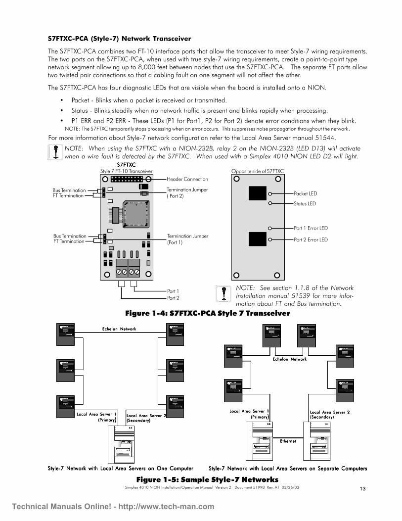
S7FTXC-PCA (Style-7) Network Transceiver
The S7FTXC-PCA combines two FT-10 interface ports that allow the transceiver to meet Style-7 wiring requirements.The two ports on the S7FTXC-PCA, when used with true style-7 wiring requirements, create a point-to-point typenetwork segment allowing up to 8,000 feet between nodes that use the S7FTXC-PCA. The separate FT ports allowtwo twisted pair connections so that a cabling fault on one segment will not affect the other.
The S7FTXC-PCA has four diagnostic LEDs that are visible when the board is installed onto a NION.
• Packet - Blinks when a packet is received or transmitted.
• Status - Blinks steadily when no network traffic is present and blinks rapidly when processing.
• P1 ERR and P2 ERR - These LEDs (P1 for Port1, P2 for Port 2) denote error conditions when they blink.NOTE: The S7FTXC temporarily stops processing when an error occurs. This suppresses noise propagation throughout the network.
Figure 1-5: Sample Style-7 Networks
For more information about Style-7 network configuration refer to the Local Area Server manual 51544.
Local Area Server 1Local Area Server 1Local Area Server 1Local Area Server 1Local Area Server 1(Pr imary(Pr imary(Pr imary(Pr imary(Pr imary )))))
Local Area Server 2Local Area Server 2Local Area Server 2Local Area Server 2Local Area Server 2(Secondary )(Secondary )(Secondary )(Secondary )(Secondary )
Echelon NetworkEchelon NetworkEchelon NetworkEchelon NetworkEchelon Network
Style-7 Network with Local Area Servers on One ComputerStyle-7 Network with Local Area Servers on One ComputerStyle-7 Network with Local Area Servers on One ComputerStyle-7 Network with Local Area Servers on One ComputerStyle-7 Network with Local Area Servers on One Computer
Local Area Server 2Local Area Server 2Local Area Server 2Local Area Server 2Local Area Server 2(Secondary )(Secondary )(Secondary )(Secondary )(Secondary )
NOTE: When using the S7FTXC with a NION-232B, relay 2 on the NION-232B (LED D13) will activatewhen a wire fault is detected by the S7FTXC. When used with a Simplex 4010 NION LED D2 will light.
S7FTXCS7FTXCS7FTXCS7FTXCS7FTXCStyle 7 FT-10 Transceiver
Header Connection
Port 1Port 2
Packet LED
Status LED
Port 1 Error LED
Port 2 Error LED
Opposite side of S7FTXC
Termination Jumper( Port 2)
Termination Jumper(Port 1)
Figure 1-4: S7FTXC-PCA Style 7 Transceiver
Bus TerminationFT Termination
Bus TerminationFT Termination
NOTE: See section 1.1.8 of the NetworkInstallation manual 51539 for more infor-mation about FT and Bus termination.
Technical Manuals Online! - http://www.tech-man.com

14 Simplex 4010 NION Installation/Operation Manual Version 2 Document 51998 Rev. A1 03/26/03
FOXC-PCA and DFXC-PCA Fiber Optic Network Transceivers
The FOXC-PCA allows up to 8db of attenuation per segment in a point to point configuration only.
The DFXC-PCA can operate in either a bus or a ring format. The regenerative properties of the DFXC transceiverallow runs of up to 12db of attenuation between each node, with up to 64 nodes per segment.
DFXCDFXCDFXCDFXCDFXCDual Fiber Optic Transceiver
Figure 1-6: FOXC-PCA and DFXC-PCA Fiber Optic Network Transceivers
FOXCFOXCFOXCFOXCFOXCFiber Optic Transceiver
Header Connection Header Connection
ST Style TX Connection
ST Style RX Connection
ST Style Connection
NOTE: See Section 1.1.3 of the Network Installationmanual for fiber optic cabling requirements for thesetransceivers.
Technical Manuals Online! - http://www.tech-man.com

15Simplex 4010 NION Installation/Operation Manual Version 2 Document 51998 Rev. A1 03/26/03
2.1: Simplex 4010 NION Connection
The Simplex 4010 NION provides monitoring of the Simplex 4010 FACP. This requires the use of a Simplex4010-9811 dual EIA-232 card installed in the Simplex 4010 panel.
The 4010-9811 dual EIA-232 card provides the NION the communication connection to the Simplex 4010panel via serial port B (P6) of the 4010-9811. See figure 2-2 for wiring connections.
Section Two: Simplex 4010 NION Installation andConfiguration
2
Figure 2-1: Simplex 4010 NION Architecture
Simplex 4010 FSimplex 4010 FSimplex 4010 FSimplex 4010 FSimplex 4010 FAAAAACPCPCPCPCP
UniNet™ 2000 LocalUniNet™ 2000 LocalUniNet™ 2000 LocalUniNet™ 2000 LocalUniNet™ 2000 LocalArea ServerArea ServerArea ServerArea ServerArea Server
Simplex 4010 NIONSimplex 4010 NIONSimplex 4010 NIONSimplex 4010 NIONSimplex 4010 NION
NIONNIONNIONNIONNION
EchelonTEchelonTEchelonTEchelonTEchelonTo Other Nodeso Other Nodeso Other Nodeso Other Nodeso Other Nodes
Ethernet TEthernet TEthernet TEthernet TEthernet To Other Wo Other Wo Other Wo Other Wo Other Workstations,orkstations,orkstations,orkstations,orkstations,Servers, etc.Servers, etc.Servers, etc.Servers, etc.Servers, etc.
4-wire EIA-2324-wire EIA-2324-wire EIA-2324-wire EIA-2324-wire EIA-232Connection to SimplexConnection to SimplexConnection to SimplexConnection to SimplexConnection to Simplex4010-9811 Dual EIA-4010-9811 Dual EIA-4010-9811 Dual EIA-4010-9811 Dual EIA-4010-9811 Dual EIA-
232 Card P232 Card P232 Card P232 Card P232 Card Port Bort Bort Bort Bort B
SimplexSimplexSimplexSimplexSimplex4010 NION4010 NION4010 NION4010 NION4010 NION
Simplex 4010 FSimplex 4010 FSimplex 4010 FSimplex 4010 FSimplex 4010 FAAAAACPCPCPCPCP
NOTE: Use only wire for power limited systems.Power limited wire runs use type FPLR, FPLP, FPL orequivalent cabling per NEC 760.
Technical Manuals Online! - http://www.tech-man.com

16 Simplex 4010 NION Installation/Operation Manual Version 2 Document 51998 Rev. A1 03/26/03
Simplex 4010-9811 DualSimplex 4010-9811 DualSimplex 4010-9811 DualSimplex 4010-9811 DualSimplex 4010-9811 DualEIA-232 CardEIA-232 CardEIA-232 CardEIA-232 CardEIA-232 Card
Simplex 4010 NIONSimplex 4010 NIONSimplex 4010 NIONSimplex 4010 NIONSimplex 4010 NION
TB1TB1TB1TB1TB1
Serial PSerial PSerial PSerial PSerial Port B (P6)ort B (P6)ort B (P6)ort B (P6)ort B (P6)
Figure 2-2: Simplex 4010 NION to Simplex 4010-9811 Serial Connections
Serial Connections
The Simplex 4010 NION requires that a Simplex model 4010-9811 dual EIA-232 card be installed in the Simplex4010 FACP. The NION communicates to the 4010 FACP through serial port P6 onboard the 4010-9811 card.
Figure 2-2 diagrams the wiring between TB1 of the NION and P6 (Serial Port B) of the 4010-9811.
Serial Communication Settings
The EIA-232 settings of the NION are 9600 baud, 8 data bits, No parity and 1 stop bit. The Simplex 4010 firepanel must match these settings in order for the NION to communicate with the panel properly.
NOTE: Use only wire for power limitedsystems. Power limited wire runs usetype FPLR, FPLP, FPL or equivalentcabling per NEC 760.
Technical Manuals Online! - http://www.tech-man.com

17Simplex 4010 NION Installation/Operation Manual Version 2 Document 51998 Rev. A1 03/26/03
2.2: Simplex 4010 NION Enclosure and Mounting
For NION mounting applications where power is supplied by the monitored equipment or an external source, theNISCAB-1 should be used. This enclosure is provided with door and key lock.
Mounting the enclosure to its wall position
1) Use the provided key to unlock the enclosure cover.
2) Remove the enclosure cover.
3) Mount the enclosure to the wall. Refer to the enclosure mounting hole layout below.
Figure 2-4: NISCAB-1 Enclosure Mounting Hole Layout
Power Requirements and Connection
The Simplex 4010 NION requires24VDC @ 250mA nominal inaccordance with local code require-ments. It can be powered by anypower limited, regulated source thatis UL listed for use with fire protectivesignaling units.
+24VDC+24VDC+24VDC+24VDC+24VDCGNDGNDGNDGNDGND
Simplex 4010 NIONSimplex 4010 NIONSimplex 4010 NIONSimplex 4010 NIONSimplex 4010 NION
Figure 2-3: Simplex 4010 NION Power Connection
Technical Manuals Online! - http://www.tech-man.com

18 Simplex 4010 NION Installation/Operation Manual Version 2 Document 51998 Rev. A1 03/26/03
2.3 Event Reporting and Acknowledgement
Event Reporting
The Simplex 4010 NION reports events to a UniNet™ 2000 workstation in the format LllDddd where ll is the loopand ddd the device. The Simplex 4010 FACP has one loop capable of handling 250 devices. If, for example,device 001 on loop 01 goes into alarm or trouble the UniNet™ 2000 workstation will display the device asL01D001. Note that all event reporting of the Simplex 4010 NION is strictly ancillary.
Event Acknowledgement
All events of the Simplex 4010 must be acknowledged at the panel. Acknowledging an event from the UniNet™2000 workstation will not acknowledge the event on the Simplex 4010 panel.
Mounting Studs w/StandoffsMounting Studs w/StandoffsMounting Studs w/StandoffsMounting Studs w/StandoffsMounting Studs w/StandoffsMounting Studs w/StandoffsMounting Studs w/StandoffsMounting Studs w/StandoffsMounting Studs w/StandoffsMounting Studs w/Standoffs
Figure 2-5: Installing the NION in a NISCAB-1
Mounting NION boards withinthe enclosureWhen installing single NION boards inthis enclosure, be sure to use theinboard set of four mounting studs asshown below.
NOTE: This enclosure mustcontain power limited wiring only.
NOTE: Use only wire for powerlimited systems. Power limited wireruns use type FPLR, FPLP, FPL orequivalent cabling per NEC 760.
Simplex 4010 NIONSimplex 4010 NIONSimplex 4010 NIONSimplex 4010 NIONSimplex 4010 NION
NISCAB-1NISCAB-1NISCAB-1NISCAB-1NISCAB-1
NOTE: The Simplex 4010 Panel reports all battery charger events as panel events.
NOTE: The Simplex 4010 panel supports custom labels for devices. These customlabels are shown in the description field of the device at the workstation. Howeverthe ampersand (&), star. (*), plus (+), pound (#), comma (,), apostrophe (‘), caret(^), and at (@) characters, if used in the custom label, will not be displayed in thedevice description field at the workstation.
Technical Manuals Online! - http://www.tech-man.com

19Simplex 4010 NION Installation/Operation Manual Version 2 Document 51998 Rev. A1 03/26/03
3Section Three: Simplex 4010 NION Explorer3.1 Simplex Explorer Overview
The Simplex 4010 NION Explorer is a plug-in application that provides the ability to view panel information andNION configurations from a UniNet™ 2000 workstation. The Simplex Explorer operates much like WindowsExplorer. It displays NION and Panel information in expandable menus the same way Windows Explorer displaysthe file system in expandable file folders.
3.2 Simplex 4010 Explorer Operation
3.2.1 Registering and Opening the Simplex Explorer
To open the Simplex Explorer application from the UniNet™ 2000 workstation it must first be properly registeredwith the appropriate NION type. This is done through the workstation by a two-step process.
• From the UniNet™ Workstation (UWS), go to the Workstation Configuration menu and select NionApplications. Locate the NION Type drop-down box. Scroll through the drop-down list and select theSimplex 4010 NION. Click the CHANGE button on the form. This will cause a dialogue box to bedisplayed with the names of all available configuration files. Select SX4010.cfg and then click the OPENbutton. Finally, click DONE to end the registration process.
• From the UWS, go to the Tools menu and click on Node Control Selection. Take control of the node byclicking on the node number for the Simplex 4010 NION, then click on the button labeled ActivateControl For This Node. Click on the DONE button to end the process.
Once the Simplex plug-in is registered it is opened by right-clicking on any device associated with a Simplex 4010NION and selecting Simplex 4010 Explorer from the pop-up menu.
3.2.2 The Simplex 4010 Explorer Main Form
Like Windows Explorer, the Simplex Explorer screen is displayed as two panes. The left pane displays the expand-able list of panel and NION properties, while the right pane shows detailed information about the particular itemhighlighted. Navigate through the devices associated with a Simplex 4010 Panel simply by expanding andcollapsing the menu in the left pane. Highlighting a device in the menu will display its properties and value in theright pane.
Technical Manuals Online! - http://www.tech-man.com

20 Simplex 4010 NION Installation/Operation Manual Version 2 Document 51998 Rev. A1 03/26/03
The Simplex 4010 Explorer Main Screen consists of the following:
Update button - Saves configuration changes made with Simplex Explorer to the NION.
Undo button - Cancels any configuration changes made in the plug-in.
Exit button - Closes the Simplex Explorer.
Arrange button - Toggles the Simplex 4010 Explorer window to be always on top or moved to the backgroundwhen an event occurs.
Panels tree - Displays the Simplex 4010 NION on the system and the associated Simplex 4010 panel inexpandable\collapsible menus.
Property and Value data display - The right half of the form displays the Property and Value of the device high-lighted in the Panels tree.
Object window - Displays the path to the device currently highlighted in the Panels tree.
3.2.3 Configuring the NION through Simplex 4010 Explorer
The Simplex 4010 NION is easily configured to communicate with a Simplex 4010 FACP via the Simplex 4010Explorer. Only an operator with administrator privileges can access configuration tools. To configure the NIONonce Simplex Explorer is open, right-click on the NION item in the Panels tree to display a pop-up menu. Themenu items in this menu are used to configure the Simplex 4010 NION.
Figure 3-2: NION-Simplex 4010 Configuration Menu
Figure 3-1: Simplex 4010 Explorer
PPPPPanels Tanels Tanels Tanels Tanels Treereereereeree
Data Display AreaData Display AreaData Display AreaData Display AreaData Display Area
Object WindowObject WindowObject WindowObject WindowObject Window
Update ButtonUpdate ButtonUpdate ButtonUpdate ButtonUpdate Button
Arrange ButtonArrange ButtonArrange ButtonArrange ButtonArrange Button
Exit ButtonExit ButtonExit ButtonExit ButtonExit Button
Undo ButtonUndo ButtonUndo ButtonUndo ButtonUndo Button
Technical Manuals Online! - http://www.tech-man.com

21Simplex 4010 NION Installation/Operation Manual Version 2 Document 51998 Rev. A1 03/26/03
NION-Simplex 4010 Configuration Menu
LLLLLearn Pearn Pearn Pearn Pearn Panel Devicesanel Devicesanel Devicesanel Devicesanel Devices - This selection allows the NION to learn, or self program, all the devices associated withthe Simplex 4010 panel it is connected to. This selection will start a panel learn session and the data display areawill show a progress bar and the number of device types the NION has detected on the panel. When the panellearn session is complete, a message will appear. Click OK and click the Close button. The Simplex 4010NION is now configured with the Simplex 4010 devices.
Figure 3-3: Learn Panel Devices Session
NOTE: The Learn PanelDevices session is a lengthyprocess. Please allow severalminutes for this operation.
NOTE: The NION will notfunction properly unless aPanel Learn session isexecuted. If devices orlabels are added orchanged, a Panel Learnmust be performed again.
Figure 3-4: Duplicate Device Labels
The Simplex 4010 devices must not have any duplicate device labels. If duplicate device labels are found during apanel learn session, a message will appear on the Simplex Explorer screen. If any duplicates are found, theSimplex NION Explorer creates a log file and saves it in the C:\UniNet\PlugIns\Data\ file folder, with a file nameof Simplex4010_node_XXX_duplicates.log (where XXX denotes the NION number). This file will list all dupli-cate labels and their addresses. All point labels must be unique for proper functionality.
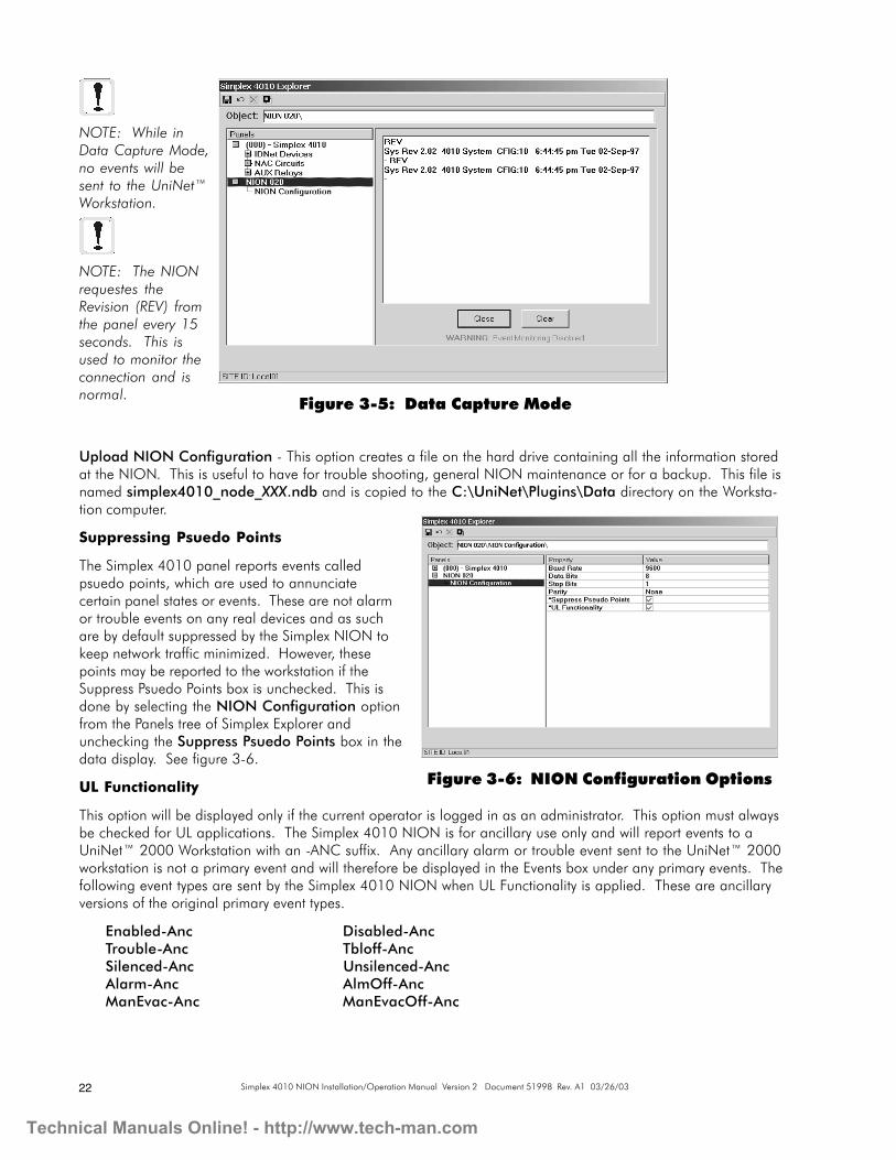
Enter Data Capture ModeEnter Data Capture ModeEnter Data Capture ModeEnter Data Capture ModeEnter Data Capture Mode - This selection changes the data display into a display of panel messages fortroubleshooting purposes. Simplex Explorer gives the option to save this information as a log file when Enter DataCapture Mode is first selected. This file is written as follows:
C:\UniNet\PlugIns\Data\Simplex 4010_node_XXX_data_capture.log
Technical Manuals Online! - http://www.tech-man.com
22 Simplex 4010 NION Installation/Operation Manual Version 2 Document 51998 Rev. A1 03/26/03
Upload NION Configuration - This option creates a file on the hard drive containing all the information storedat the NION. This is useful to have for trouble shooting, general NION maintenance or for a backup. This file isnamed simplex4010_node_XXX.ndb and is copied to the C:\UniNet\Plugins\Data directory on the Worksta-tion computer.
Suppressing Psuedo Points
The Simplex 4010 panel reports events calledpsuedo points, which are used to annunciatecertain panel states or events. These are not alarmor trouble events on any real devices and as suchare by default suppressed by the Simplex NION tokeep network traffic minimized. However, thesepoints may be reported to the workstation if theSuppress Psuedo Points box is unchecked. This isdone by selecting the NION Configuration optionfrom the Panels tree of Simplex Explorer andunchecking the Suppress Psuedo Points box in thedata display. See figure 3-6.
UL Functionality
This option will be displayed only if the current operator is logged in as an administrator. This option must alwaysbe checked for UL applications. The Simplex 4010 NION is for ancillary use only and will report events to aUniNet™ 2000 Workstation with an -ANC suffix. Any ancillary alarm or trouble event sent to the UniNet™ 2000workstation is not a primary event and will therefore be displayed in the Events box under any primary events. Thefollowing event types are sent by the Simplex 4010 NION when UL Functionality is applied. These are ancillaryversions of the original primary event types.
Enabled-Anc Disabled-AncTrouble-Anc Tbloff-AncSilenced-Anc Unsilenced-AncAlarm-Anc AlmOff-AncManEvac-Anc ManEvacOff-Anc
Figure 3-5: Data Capture Mode
NOTE: While inData Capture Mode,no events will besent to the UniNet™Workstation.
NOTE: The NIONrequestes theRevision (REV) fromthe panel every 15seconds. This isused to monitor theconnection and isnormal.
Figure 3-6: NION Configuration Options
Technical Manuals Online! - http://www.tech-man.com

23Simplex 4010 NION Installation/Operation Manual Version 2 Document 51998 Rev. A1 03/26/03
SymbolsSymbolsSymbolsSymbolsSymbols
2DRN Board LayoutJ2,J3 Pin Connections 10J6 Pin Connections Headers for SMX Xvr 10
4010-9811 dual EIA-232 15
EEEEE
Enclosure 17Event Reporting Format 18
FFFFF
Fiber Optic Network Transceivers 14fiber-optic cable 11
MMMMM
Mounting 17
NNNNN
NFN ExplorerOverview 19
NION-NPB 9NISCAB-1 17
PPPPP
Power Requirements 11
RRRRR
Required Equipment 9
IndexSSSSS
Serial Communication Settings 16Serial Connections 16Simplex 4010 NION Explorer
Registering and Opening the Simplex Explorer 19Simplex Explorer Main Form 19
Simplex Explorer Main Form 19SMX Network Transceivers 12
DFXC-PCA 14FOXC-PCA 14FTXC-PCA 12FTXC-PCB 12S7FTXC-PCA 13
Style-7 wiring 13
TTTTT
Twisted pair cable 11
Technical Manuals Online! - http://www.tech-man.com

24 Simplex 4010 NION Installation/Operation Manual Version 2 Document 51998 Rev. A1 03/26/03
NOTIFIER® warrants its products to be free from defects in materials and workmanshipfor eighteen (18) months from the date of manufacture, under normal use and service.Products are date stamped at time of manufacture. The sole and exclusive obligationof NOTIFIER® is to repair or replace, at its option, free of charge for parts and labor,any part which is defective in materials or workmanship under normal use and service.For products not under NOTIFIER® manufacturing date-stamp control, the warrantyis eighteen (18) months from date of original purchase by NOTIFIER®'s distributorunless the installation instructions or catalog sets forth a shorter period, in which casethe shorter period shall apply. This warranty is void if the product is altered, repairedor serviced by anyone other than NOTIFIER® or its authorized distributors or if thereis a failure to maintain the products and systems in which they operate in a properand workable manner. In case of defect, secure a Return Material Authorization formfrom our customer service department. Return product, transportation prepaid, toNOTIFIER®, 12 Clintonville Road, Northford, Connecticut 06472-1653.
This writing constitutes the only warranty made by NOTIFIER® with respect to itsproducts. NOTIFIER® does not represent that its products will prevent any loss byfire or otherwise, or that its products will in all cases provide the protection forwhich they are installed or intended. Buyer acknowledges that NOTIFIER® is notan insurer and assumes no risk for loss or damages or the cost of any inconvenience,transportation, damage, misuse, abuse, accident or similar incident.
NOTIFIER® GIVES NO WARRANTY, EXPRESSED OR IMPLIED, OFMERCHANTABILITY, FITNESS FOR ANY PARTICULAR PURPOSE, OROTHERWISE WHICH EXTEND BEYOND THE DESCRIPTION ON THE FACEHEREOF. UNDER NO CIRCUMSTANCES SHALL NOTIFIER® BE LIABLE FORANY LOSS OF OR DAMAGE TO PROPERTY, DIRECT, INCIDENTAL ORCONSEQUENTIAL, ARISING OUT OF THE USE OF, OR INABILITY TO USENOTIFIER® PRODUCTS. FURTHERMORE, NOTIFIER® SHALL NOT BE LIABLEFOR ANY PERSONAL INJURY OR DEATH WHICH MAY ARISE IN THE COURSEOF, OR AS A RESULT OF, PERSONAL, COMMERCIAL OR INDUSTRIAL USEOF ITS PRODUCTS.
This warranty replaces all previous warranties and is the only warranty made byNOTIFIER®. No increase or alteration, written or verbal, of the obligation of thiswarranty is authorized.
"NOTIFIER" is a registered trademark.
Limited Warranty
Technical Manuals Online! - http://www.tech-man.com