4010-9810 and -9816 DACTs (Digital Alarm …...4010-9810 and -9816 DACTs (Digital Alarm...
14
4010-9810 and -9816 DACTs (Digital Alarm Communication Transmitters) Installation Instructions 2000 Simplex Time Recorder Co., Westminster, MA 01441-0001 USA All specifications and other information shown were current as of publication, and are subject to change without notice 574-167 Rev. E DO NOT INSTALL ANY SIMPLEX PRODUCT THAT APPEARS DAMAGED. Upon unpacking your Simplex product, inspect the contents of the carton for shipping damage. If damage is apparent, immediately file a claim with the carrier and notify Simplex. ELECTRICAL HAZARD - Disconnect electrical power when making any internal adjustments or repairs. Servicing should be performed by qualified Simplex Representatives. STATIC HAZARD - Static electricity can damage components. Therefore, handle as follows: 1. Ground yourself before opening or installing components (use the 553-484 Static Control Kit). 2. Keep uninstalled components wrapped in anti-static material at all times. RADIO FREQUENCY ENERGY - This equipment generates, uses, and can radiate radio frequency energy and if not installed and used in accordance with the instruction manual, may cause interference to radio communications. It has been tested and found to comply with the limits for a Class A computing device pursuant to Subpart J of Part 15 of FCC Rules, which are designed to provide reasonable protection against such interference when operated in a commercial environment. Operation of this equipment in a residential area may cause interference in which case the user at his own expense will be required to take whatever measures may be required to correct the interference. This publication shows how to install the 4010-9810 Common Event Reporting or 4010-9816 Point Reporting Digital Alarm Communication Transmitter (DACT) Cards into a 4010 Fire Alarm Control Panel (FACP). Only one of these option cards is allowed per system. You cannot have a 4010 DACT card and a network interface card in the same 4010 FACP. Refer to the Serial DACT Installation/Programming Instructions (574-090) for configuration information. Refer to the 842-058 Field Wiring Diagram for additional wiring information. This publication discusses the following topics: Topic See Page # Overview 1 FCC and IC Requirements 2 4010-9810 DACT Card 5 4010-9816 DACT Card 6 Configuration 7 Wiring 8 Card Installation 9 Compatible Receivers 12 Cautions and Warnings Overview In this Publication Technical Manuals Online! - http://www.tech-man.com
Transcript of 4010-9810 and -9816 DACTs (Digital Alarm …...4010-9810 and -9816 DACTs (Digital Alarm...

4010-9810 and -9816 DACTs(Digital Alarm Communication
Transmitters) Installation Instructions
2000 Simplex Time Recorder Co., Westminster, MA 01441-0001 USAAll specifications and other information shown were current as of publication, and are subject to change without notice
574-167Rev. E
DO NOT INSTALL ANY SIMPLEX PRODUCT THAT APPEARSDAMAGED. Upon unpacking your Simplex product, inspect the contents of thecarton for shipping damage. If damage is apparent, immediately file a claimwith the carrier and notify Simplex.
ELECTRICAL HAZARD - Disconnect electrical power when making anyinternal adjustments or repairs. Servicing should be performed by qualifiedSimplex Representatives.
STATIC HAZARD - Static electricity can damage components. Therefore,handle as follows:1. Ground yourself before opening or installing components (use the 553-484
Static Control Kit).2. Keep uninstalled components wrapped in anti-static material at all times.
RADIO FREQUENCY ENERGY - This equipment generates, uses, and canradiate radio frequency energy and if not installed and used in accordance withthe instruction manual, may cause interference to radio communications. It hasbeen tested and found to comply with the limits for a Class A computing devicepursuant to Subpart J of Part 15 of FCC Rules, which are designed to providereasonable protection against such interference when operated in a commercialenvironment. Operation of this equipment in a residential area may causeinterference in which case the user at his own expense will be required to takewhatever measures may be required to correct the interference.
This publication shows how to install the 4010-9810 Common Event Reportingor 4010-9816 Point Reporting Digital Alarm Communication Transmitter(DACT) Cards into a 4010 Fire Alarm Control Panel (FACP). Only one of theseoption cards is allowed per system. You cannot have a 4010 DACT card and anetwork interface card in the same 4010 FACP. Refer to the Serial DACTInstallation/Programming Instructions (574-090) for configuration information.Refer to the 842-058 Field Wiring Diagram for additional wiring information.
This publication discusses the following topics:
Topic See Page #
Overview 1
FCC and IC Requirements 2
4010-9810 DACT Card 5
4010-9816 DACT Card 6
Configuration 7
Wiring 8
Card Installation 9
Compatible Receivers 12
Cautions and Warnings
Overview
In this Publication
Technical Manuals Online! - http://www.tech-man.com

2
1. The Federal Communications Commission (FCC) has established Ruleswhich permit this device to be directly connected to the telephone network.Standardized jacks are used for these connections. This equipment shouldnot be used on party lines or coin lines.
2. If this device is malfunctioning, it may also be causing harm to thetelephone network; this device should be disconnected until the source ofthe problem can be determined and until repair has been made. If this is notdone, the telephone company may temporarily disconnect service.
3. The telephone company may make changes in its technical operations andprocedures; if such changes affect the compatibility or use of this device, thetelephone company is required to give adequate notice of the changes.
4. If the telephone company requests information on what equipment isconnected to their lines, inform them of:
a) The telephone number that this unit is connected to,
b) The Ringer Equivalence Number [0.1B]
c) The USOC jack required [RJ31X], and
d) The FCC Registration Number [5QWUSA-32102-AL-E] Items (b) and (d) are indicated on the label. The ringer equivalence number(REN) is used to determine how many devices can be connected to yourtelephone line. In most areas, the sum of the RENs of all device on any oneline should not exceed five (5.0). If too many devices are attached, theymay not ring properly.
In the event of equipment malfunction, all repairs should be performed by ourCompany or an authorized agent. It is the responsibility of users requiringservice to report the need for service to our Company or to one of our authorizedagents. Service can be facilitated through our office at:
Simplex Time Recorder100 Simplex Drive
Westminster, MA 01441TEL: (978) 731-2500
Continued on next page
FCC and IC Requirements
FCC Requirements
Service Requirements
Technical Manuals Online! - http://www.tech-man.com

3
“NOTICE: The Industry Canada label identifies certified equipment. Thiscertification means that the equipment meets certain telecommunicationsnetwork protective, operational and safety requirements as prescribed in theappropriate Terminal Equipment Technical Requirements document(s). TheDepartment does not guarantee the equipment will operate to the user’ssatisfaction.
Before installing this equipment, users should ensure that it is permissible to beconnected to the facilities of the local telecommunications company. Theequipment must also be installed using an acceptable method of connection. Thecustomer should be aware that compliance with the above conditions may notprevent degradation of service in some situations.
Repairs to certified equipment should be coordinated by a representativedesignated by the supplier. Any repairs or alterations made by the user to thisequipment, or equipment malfunctions, may give the telecommunicationscompany cause to request the user to disconnect the equipment.
Users should ensure for their own protection that the electrical groundconnections of the power utility, telephone lines and internal metallic water pipesystem, if present, are connected together. This precaution may be particularlyimportant in rural areas.
CAUTION: Users should not attempt to make such connectionsthemselves, but should contact the appropriate electricinspection authority, or electrician, as appropriate.
The Ringer Equivalence Number (REN) assigned to each terminal deviceprovides an indication of the maximum number of terminals allowed to beconnected to a telephone interface. The termination on an interface may consistof any combination of devices subject only to the requirement that the sum of theRinger Equivalence Numbers of all the devices does not exceed 5.”
Continued on next page
FCC and IC Requirements, Continued
Equipment AttachmentLimitations
Technical Manuals Online! - http://www.tech-man.com
4
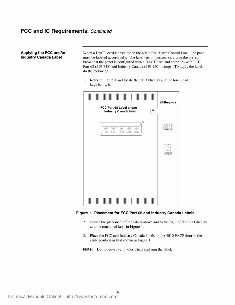
When a DACT card is installed in the 4010 Fire Alarm Control Panel, the panelmust be labeled accordingly. The label lets all persons servicing the systemknow that the panel is configured with a DACT card and complies with FCCPart 68 (519-748) and Industry Canada (519-750) listings. To apply the label,do the following:
1. Refer to Figure 1 and locate the LCD Display and the touch padkeys below it.
Figure 1. Placement for FCC Part 68 and Industry Canada Labels 2. Notice the placement of the labels above and to the right of the LCD display
and the touch pad keys in Figure 1. 3. Place the FCC and Industry Canada labels on the 4010 FACP door in the
same position as that shown in Figure 1.
Note: Do not cover vent holes when applying the label.
FCC and IC Requirements, Continued
Applying the FCC and/orIndustry Canada Label
FCC Part 68 Label and/orIndustry Canada label.
Technical Manuals Online! - http://www.tech-man.com

5
The 4010-9810 DACT card (742-155) supports five categories of status changes.The Central Station is notified of Alarm, Trouble, and Supervisory status changes.AC Fail trouble is delayed from 6-24 hours before reporting to the Central Station.The DACT supervises the system CPU via the N2 communications. In the event ofa CPU failure, the card sends a “CPU Trouble” message to the Central Station.
Figure 2 shows the location of connectors and switches.
To Programmer
SW1 SW2 P4
Line 1
Line 2P5
P6D.A.C.T. Assy 565-860
8 1 On
Figure 2. 4010-9810 Common Event Reporting DACT (742-155)
4010-9810 DACT Card
Overview
To TELCORJ31X Jack
RJ45 Connector(733-986)
Pin 8 = TipHPin 5 = TipPin 4 = RingPin 1 = RingH
DACT Assy.565-860 or566-156
Technical Manuals Online! - http://www.tech-man.com

6
Specific information that is available about which point in the systemexperiences a status change is supported by the 4010-9816 Point ReportingDACT card (742-094). The report sent to the Central Station includes thespecific CID Point address along with the point status. The Point ReportingDACT supervises the system CPU via N2 communication. In the event of aCPU failure, the DACT sends a “CPU Trouble” message to the Central Station.
Figure 3 shows the location of connectors and switches.
To Telco Line
SW1 SW2 P4
Line 1
Line 2P5
P6D.A.C.T. Assy 565-798
8 1 On
Figure 3. 4010-9816 Point Reporting DACT Card (742-094)
4010-9816 DACT Card
Overview
To Programmer
To TELCORJ31X Jack
RJ45 Connector(733-986)
Pin 8 = TipHPin 5 = TipPin 4 = RingPin 1 = RingH
DACT Assy.565-798 or566-155
Technical Manuals Online! - http://www.tech-man.com

7
Card Address Setting (SW1)
Option cards in the 4010 system have specific addresses. The card addresssetting for both the DACT cards is Card 8. Set SW1-4 to the ON position andset the remaining DIP switches to the OFF position.
To self-test the DACTs, set SW1-8 to the ON position. To return the DACTs tonormal panel operation, set SW1-8 to the OFF position.
Programmer (SW2)
When interfacing with the DACT programmer, set SW2 to the ON position. SetSW2 to the OFF position for normal panel operation.
Configuration
Switch Settings
Technical Manuals Online! - http://www.tech-man.com

8
Have the telephone company install two telephone lines, each terminated with aUL-Listed RJ-31X jack immediately above or as close as possible to the FACP.The connection to the RJ-31X MUST be made via the listed modular jack ininstallations where the DACT shares the telephone line with premises phones, orother equipment. Connect a UL-Listed RJ45 connector and cable (733-986)from the DACT to the RJ31X jack.
Note: The two telephone line harnesses must take separate paths fromthe host FACP to the RJ-31X blocks.
1 2 3 4 5 6 7 8
BL O BK R G Y BN S
R1 * A R T A1 * T1
Two shorting bars complete the connection of premises phones to the incoming line upon removal of the direct-connect plug. Shorting bars open upon insertion of the plug.
TR
RJ-31X
1 3
4
5
87
2
6
Incoming Telephone Line
Jack Configuration Premises Phones
Pro
tect
or
Testing: (direct connect cord plugged in) Communicator Active: Terminals TIP and RING should read <5V. Communicator Inactive: Measurement across Terminals 4 and 5 should read approximately -48V.
To DACT
Figure 4. Telephone Company Wiring
Wiring
Telephone Wiring
RJ45 Connector733-986
Technical Manuals Online! - http://www.tech-man.com

9
Install a single DACT card in Expansion Slot 2 shown in Figure 5. When anoption card is already present, install the additional option card in ExpansionSlot 1. Each option card comes with all necessary harnesses and mountinghardware. Use Steps 1 through 5 to install either card into the 4010 FACP.
1. Disconnect battery and then AC power from the FACP.
2. Set all appropriate DIP switch settings and terminate all wiring to theirappropriate connectors.
3. Slide the option card into the appropriate expansion slot (see Figure 5).
Figure 5. Option Card Expansion Slots
Continued on next page
Card Installation
Mounting
Expansion Slot 1
Expansion Slot 2
Technical Manuals Online! - http://www.tech-man.com

10
4. Using the screw and lockwasher provided, secure the mounting bracket tothe system chassis (see Figure 6).
Figure 6. Option Card Mounting Bracket
5. Slide the card lock bracket into the bottom hole in the option card. Securethe bottom of the option card by tightening the card lock bracket screw(see Figure 7).
Figure 7. Card Lock Bracket
Continued on next page
Card Installation, Continued
Mounting (continued)
Mounting HoleMounting Bracket at the top
of the DACT Card
DACT Card
Card Lock Bracket
Technical Manuals Online! - http://www.tech-man.com

11
Each DACT card comes with two N2 Communications/Power Harnesses; the733-953 is a long harness used to interface the option card with the FACP, the733-956 is a short harness used to “daisy-chain” one option card to another.
Use Steps 1 through 4 to connect the N2 Communications from the option cardto the FACP.
1. Remove battery and then AC power from the FACP.
2. Verify that all switches are set correctly.
3. Using the 733-953 harness, connect one end from P1 of the option card toP1 of the 4010 FACP. P1 on the FACP is located between TB2 and TB3(see Figure 5).
IMPORTANT: Pay careful attention to the routing for Power-Limited and Non Power-Limited wiring. You mustmaintain a 1/4-inch separation between these twotypes of wiring. Neatly dress all harnesses andwiring. (See Figure 8 below.)
4. If another option card is installed that is already connected to the FACP, usethe 733-956 harness to connect P2 of one option card to P2 of the other. Youcan now apply AC and then battery power.
565-792OR
565-793 + - + -
CITYCONNECT565-577
Figure 8. Wiring Information
Card Installation, Continued
N2 Communications/PowerConnections
Battery AreaNo Conduit Entry or Wiring
in this Area
Non power-limited wiringallowed inshaded areaonly
Technical Manuals Online! - http://www.tech-man.com

12
Table 1 lists compatible receivers for the 4010-9810 DACT.
Table 1. 4010-9810 Compatible Receivers
Notes: 1. 10 and 20 PPS (Pulses Per Second)2. With 685-8 Line Card3. With 9032 Line Card4. With 9004 Line Card5. With Rec-11 Line Card6. These receivers are also Factory Mutual approved
Continued on next page
Compatible Receivers
4010-9810 DACT
RECEIVER
Comm.Format
Osborne/Hoffman
QuickalertModel II
ADEMCO685
(Notes 2, 6)
SilentKnight9000
SilentKnight9800
FBICP220FB
(Notes 5, 6)
RADIONICS6500
SUR-GARDMLR2-DG(Note 6)
13/1 Standard 1800/2300 Hz(Note 1)
YES YESYES
(Note 3) YES YES YES YES
23/1 Standard 1900/1400 Hz(Note 1)
YES YESYES
(Note 3) YES YES YES YES
34/2 Standard 1800/2300 Hz(Note 1)
YES YESYES
(Note 3) YES YES YES YES
44/2 Standard 1900/1400 Hz(Note 1)
YES YESYES
(Note 3) YES YES YES YES
5 SIA YES NOYES
(Note 4) YES NO NO YES
6RADIONICS BFSK1800/2300 Hz
YES YESYES
(Note 3) YES YES YES YES
7RADIONICS BFSK1900/1400 Hz
YES YESYES
(Note 3) YES YES YES YES
Technical Manuals Online! - http://www.tech-man.com

13
Table 2 lists compatible receivers for the 4010-9816 DACT.
Table 2. 4010-9816 DACT Compatible Receivers
Notes: 1. 10 and 20 PPS (Pulses Per Second)2. With 685-8 Line Card3. With 9032 Line Card4. With 9004 Line Card5. With Rec-11 Line Card6. These receivers are also Factory Mutual approved
Compatible Receivers, Continued
4010-9816 DACT
RECEIVER
Comm.Format
Osborne/Hoffman
QuickalertModel II
ADEMCO685
(Notes 2, 6)
SilentKnight9000
SilentKnight9800
FBICP220FB
(Notes 5, 6)
RADIONICS6500
SUR-GARDMLR2-DG
13/1 Standard 1800/2300 Hz(Note 1)
YES YESYES
(Note 3) YES YES YES YES
23/1 Standard 1900/1400 Hz(Note 1)
YES YESYES
(Note 3) YES YES YES YES
34/2 Standard 1800/2300 Hz(Note 1)
YES YESYES
(Note 3) YES YES YES YES
44/2 Standard 1900/1400 Hz(Note 1)
YES YESYES
(Note 3) YES YES YES YES
5ADEMCOCONTACT ID
YES YES NO YES YES NO YES
6 SIA YES NOYES
(Note 4) YES NO NO YES
7RADIONICS BFSK1800/2300 Hz
YES YESYES
(Note 3) YES YES YES YES
8RADIONICS BFSK1900/1400 Hz
YES YESYES
(Note 3) YES YES YES YES
Technical Manuals Online! - http://www.tech-man.com

574-167Rev. E
Technical Manuals Online! - http://www.tech-man.com